EP1364729B1 - Verfahren und Stranggiessvorrichtung zum Rundstranggiessen von flüssigem Metall, insbesondere von flüssigem Stahl - Google Patents
Verfahren und Stranggiessvorrichtung zum Rundstranggiessen von flüssigem Metall, insbesondere von flüssigem Stahl Download PDFInfo
- Publication number
- EP1364729B1 EP1364729B1 EP03005287A EP03005287A EP1364729B1 EP 1364729 B1 EP1364729 B1 EP 1364729B1 EP 03005287 A EP03005287 A EP 03005287A EP 03005287 A EP03005287 A EP 03005287A EP 1364729 B1 EP1364729 B1 EP 1364729B1
- Authority
- EP
- European Patent Office
- Prior art keywords
- continuous casting
- strand
- profile roller
- mould
- round
- Prior art date
- Legal status (The legal status is an assumption and is not a legal conclusion. Google has not performed a legal analysis and makes no representation as to the accuracy of the status listed.)
- Expired - Lifetime
Links
- 238000009749 continuous casting Methods 0.000 title claims abstract description 45
- 229910000831 Steel Inorganic materials 0.000 title claims abstract description 7
- 239000010959 steel Substances 0.000 title claims abstract description 7
- 238000000034 method Methods 0.000 title claims abstract description 6
- 239000002184 metal Substances 0.000 title 1
- 238000005266 casting Methods 0.000 claims abstract description 17
- 229910001338 liquidmetal Inorganic materials 0.000 claims abstract description 7
- 239000007788 liquid Substances 0.000 claims abstract description 6
- 238000004519 manufacturing process Methods 0.000 claims description 14
- 238000011144 upstream manufacturing Methods 0.000 claims description 2
- 238000009826 distribution Methods 0.000 description 8
- 230000010355 oscillation Effects 0.000 description 5
- 230000000694 effects Effects 0.000 description 2
- 239000000155 melt Substances 0.000 description 2
- 239000004020 conductor Substances 0.000 description 1
- 238000011982 device technology Methods 0.000 description 1
Images

Classifications
-
- B—PERFORMING OPERATIONS; TRANSPORTING
- B22—CASTING; POWDER METALLURGY
- B22D—CASTING OF METALS; CASTING OF OTHER SUBSTANCES BY THE SAME PROCESSES OR DEVICES
- B22D11/00—Continuous casting of metals, i.e. casting in indefinite lengths
- B22D11/14—Plants for continuous casting
- B22D11/147—Multi-strand plants
Definitions
- the invention relates to a method and a continuous casting apparatus for the continuous casting of liquid metal, in particular of liquid steel, in a multi-strand continuous casting, wherein jewells on a continuous casting mold follows a support roll stand and a plurality of strand cores run side by side parallel and wherein the continuous casting mold is fed from an upstream distribution vessel with melt ,
- Such multi-strand casting machines are built and operated for 2, 3, 4, 5, 6 or more strands.
- Each continuous casting mold is assigned an oscillation device with a lifting table.
- a plurality of continuous casting molds is also preceded by a distribution vessel. It can also be assigned several distribution boxes for groups of continuous casting molds.
- the distribution vessels are fed by a ladle of correspondingly large capacity.
- temperature differences in the melt occur in the case of external casting strands and or in the case of several distribution vessels.
- this endeavor is precluded by a production capacity intended for multi-strand casters.
- the invention is based, to match the production capacity of a Mehrstrangg intelligent fabricstrom depending on the diameter distribution on the number of casting lines the task.
- the stated object is achieved in that from a customer-specific diameter series relatively smaller strand diameter of 180-240 mm in twin molds and relatively larger strand diameter of 270-406 mm in single molds are cast simultaneously in the Rundstranggitis.
- a high production capacity is possible with a smallest possible number of casting lines, i. the relative production capacity is increased considerably.
- a higher production capacity can be achieved with a smaller number of Strangadem.
- the twin system is used and for larger strand diameters the single system, so that the casting performance of the casting line, which is cast in the twin system, each consisting of a lifting table, a Continuous casting mold and an oscillation device, doubles.
- the production capacity can be limited to such a Mehrfachstrangg imaginestrom by the existing transport facilities for the melt. Basically, it is therefore possible that the distributor is fed from a pan vessel with a maximum of 300 t capacity.
- the continuous casting apparatus for liquid metals, in particular for liquid steel, with a plurality of parallel, juxtaposed strand conductors, each formed by continuous casting molds and subsequent support roll stand with straight and / or curved course is designed device technology to the effect that the support roll stand the unitary continuous casting either from each three adjacent profile roller tracks and each each profile roller track associated with continuous casting mold is formed or from only two profile roller paths and an asymmetrically constructed continuous casting mold, which is assigned to one of the profile roller paths.
- two profile roller tracks are arranged symmetrically or asymmetrically to a central profile roller track.
- the twin system can be used here.
- the size of the Mehrfachstrangg mangifferasis can then be determined to the effect that for a given number of casting strands, the proportion of production of the individual strand diameter of the annual production is used as a guide for the design of the number of strands.
- the advantage is the consideration of a changing market demand of selected strand diameters, which form quantitative emphases.
- Each casting line 2 eliminates a continuous casting mold, a lifting table and an oscillation device, which are designated together with 3. It is cast from a customer-specific diameter row 4 for relatively small strand diameter 5 each in twin molds 6 and relatively larger strand diameters 7 in single molds 8 within the uniform continuous casting apparatus 1.
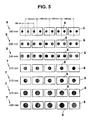
- Fig. 5 an example for the classification of strands of relatively small or larger diameter is shown: For strand diameter of approx. 180 - 240 mm, the twin system and for strand diameter of approx. 270 - 406 mm the single system is used.
- the uniform continuous casting apparatus 1 consists in each case ( Fig. 1 ) From a support roller frame 11 and forms for a relatively large strand diameter 7 each three adjacent, parallel profile roller webs 12, wherein the middle profile roller web 12 is covered by the cast strand.
- Each profile roll web 12 is associated with a continuous casting mold.
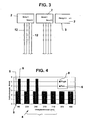
- Fig. 3 it is an asymmetrically constructed continuous casting mold within the casting line 2.
- the in Fig. 2 are arranged symmetrically to a central profile roller track 12 is in Fig. 3 the profile roller web 12 arranged correspondingly asymmetrically.
- Fig. 4 is the corresponding single mold 8 (lighter hatched) associated with the corresponding twin mold 6 (darker hatched). It can be seen that the standard diameters 180, 220 and 240 mm according to the invention produce with higher casting performance, which means Fig. 5 is immediately apparent.
Landscapes
- Engineering & Computer Science (AREA)
- Mechanical Engineering (AREA)
- Continuous Casting (AREA)
Description
- Die Erfindung betrifft ein Verfahren und eine Stranggießvorrichtung zum Rundstranggießen von flüssigem Metall, insbesondere von flüssigem Stahl, in einer mehrsträngigen Stranggießvorrichtungen, wobei jewells auf eine Stranggießkokille ein Stützrollengerüst folgt und mehrere Strangadern nebeneinander parallel verlaufen und wobei die Stranggießkokille aus einem vorgeschalteten Verteilergefäß mit Schmelze gespeist wird.
- Derartige Mehrstranggießmaschinen werden für 2, 3, 4, 5, 6 oder mehr Stränge gebaut und betrieben. Jeder Stranggießkokille ist eine Oszillationseinrichtung mit einem Hubtisch zugeordnet. Einer Mehrzahl von Stranggießkokillen ist ferner ein Verteilergefäß vorgeschaltet. Es können auch mehrere Verteilergefäße für Gruppen von Stranggießkokillen zugeteilt sein. Die Verteilergefäße werden von einer Gießpfanne entsprechend großen Fassungsvermögens gespeist. Jedoch treten dabei schon Temperaturunterschiede in der Schmelze bei außen liegenden Gießsträngen und oder bei mehreren Verteilergefäßen auf. Man ist daher bestrebt, die Anzahl der Strangadern zu begrenzen. Diesem Bestreben steht jedoch eine für Mehrstranggießanlagen vorgesehene Produktionsleistung entgegen. Hinzu kommen unterschiedlich große Strangdurchmesser, die sich aus wechselnden Marktforderungen ergeben.
- Den bekannten Mehrstranggießanlagen haften daher Nachteile einer mangelhaften Koordinierung der Produktionsleistung und der Durchmesserverteilung mit der Anzahl der Stränge an. Ebenso sind die Tomperaturführung, die Verteilergrößen, die Anzahl der Hubtische mit Oszillationseinrichtungen und Stranggießkokillen besser aufeinander abzustimmen.
- Der Erfindung liegt die Aufgabe zugrunde, die Produktionsleistung einer Mehrstranggießanlage in Abhängigkeit der Durchmesserverteilung auf die Anzahl von Gießlinien abzustimmen.
- Die gestellte Aufgabe wird erfindungsgemäß dadurch gelöst, dass aus einer kundenspezifischen Durchmesserreihe relativ kleinere Strangdurchmesser von 180-240 mm in Twin-Kokillen und relativ größere Strangdurchmesser von 270-406 mm in Single-Kokillen gleichzeitig in der Rundstranggießanlage vergossen werden. Dadurch ist eine hohe Produktionsleistung mit einer kleinstmöglichen Anzahl von Gießlinien möglich, d.h. die relative Produktionsleistung wird erheblich gesteigert. Dabei kann eine höhere Produktionsleistung mit einer geringeren Anzahl von Strangadem erzielt werden.
- Für kleinere Strangdurchmesser wird das Twin-System eingesetzt und für größere Strangdurchmesser das Single-System, so dass die Gießleistung der Gießlinie, auf der im Twin-System gegossen wird, jeweils bestehend aus einem Hubtisch, einer Stranggießkokille und einer Oszülationseinrichtung, sich verdoppelt.
- Die Produktionsleistung kann an einer solchen Mehrfachstranggießanlage durch die vorhandenen Transportanlagen für die Schmelze begrenzt werden. Im Grunde ist daher möglich, dass der Verteiler aus einem Pfannengefäß mit maximal 300 t Fassungsvermögen gespeist wird.
- Die Stranggießvorrichtung für flüssige Metalle, insbesondere für flüssigen Stahl, mit mehreren parallelen, nebeneinander angeordneten Strangadern, die jeweils durch Stranggießkokillen und anschließendem Stützrollengerüst mit geradem und / oder gebogenem Verlauf gebildet sind, ist vorrichtungstechnisch dahingehend gestaltet, dass das Stützrollengerüst der einheitlichen Stranggießvorrichtung entweder aus jeweils drei nebeneinander angeordneten Profilrollen-Bahnen und jeweils jeder Profilrollen-Bahn zugeordneter Stranggießkokille gebildet ist oder aus nur zwei ProfilrollenBahnen und einer asymmetrisch aufgebauten Stranggießkokille, die jeweils einer der Profilrollen-Bahnen zugeordnet ist. Dadurch können temperaturbedingte Abstände zwischen den Strängen leicht eingehalten werden, wobei sowohl Stränge mit kleinem Durchmesser in Paaren als auch ein mittlerer Strang mit größerem Durchmesser auf der Anlage gegossen werden kann und nur die Hubtischeinheit anzupassen ist.
- Nach weiteren Merkmalen ist vorgesehen, dass zwei Profilrollen-Bahnen symmetrisch oder unsymmetrisch zu einer mittleren Profilrollen-Bahn angeordnet sind. Dabei kann das Twin-System eingesetzt werden.
- Die Größe der Mehrfachstranggießanlage kann sodann dahingehend bestimmt werden, dass bei einer vorgegebenen Anzahl der Gießstränge der Anteil der Produktion der einzelnen Strangdurchmesser an der Jahresproduktion als Richtwert für die Auslegung der Anzahl der Stränge dient. Der Vorteil ist die Berücksichtigung einer wechselnden Marktforderung von ausgewählten Strangdurchmessern, die mengenmäßige Schwerpunkte bilden.
- In der Zeichnung sind Ausführungsbeispiele der Erfindung dargestellt, die nachstehend näher erläutert werden.
- Es zeigen:
- Fig. 1
- mehrere Gießlinien für relativ dicke Stränge, die jeweils in einer mittigen Profilrollen-Bahn geführt sind,
- Fig. 2
- mehrere Gießlinien für relativ dünne Stränge, die jeweils in außen liegenden Profilrollen-Bahnen geführt werden,
- Fig. 3
- mehrere Gießlinien für relativ dünne Stränge und mit einer asymmetrisch aufgebauten Stranggießkokille,
- Fig. 4
- ein Diagramm der Gießstrangproduktions-Leistung über der Durchmesserverteilung mit den bekannten und den erfindungsgemäßen Produktionsleistungen und
- Fig. 5
- die schematische Zuordnung der einzelnen Durchmesser zu Twin- oder Single-Systeme der Stranggießkokillen.
- Das Verfahren zum Rundstranggießen von flüssigem Metall, insbesondere von flüssigem Stahl, wird in mehrsträngigen Stranggießvorrichtungen 1 ausgeführt. Auf jede Gießlinie 2 entfällt eine Stranggießkokille, ein Hubtisch und eine Oszillationseinrichtung, die gemeinsam mit 3 bezeichnet sind. Dabei wird aus einer kundenspezifischen Durchmesserreihe 4 für relativ kleine Strangdurchmesser 5 jeweils in Twin-Kokillen 6 und relativ größeren Strangdurchmessern 7 in Single-Kokillen 8 innerhalb der einheitlichen Stranggießvorrichtung 1 vergossen.
- Die in der
Fig. 4 wiedergegebenen, den einzelnen Durchmessern zugeordneten Gießstränge sind konventionell nur einzeln vergossen, woraus sich die niedrige Gießleistung in t / min ergibt. Eine solche Anzahl mehrerer unabhängiger Mehrstranganlagen 9 mit einer summierten Produktionsleistung kann in die einheitliche Stranggießvorrichtung 1 mit einer virtuellen Stranganzahl 10 umgerechnet werden und dann wird für die summierte Produktionsleistung die Anzahl der Stränge auf eine reale, volle Anzahl reduziert. - In
Fig. 5 ist ein Beispiel für die Einteilung von Strängen relativ kleiner oder größerer Durchmesser gezeigt: Für Strangdurchmesser von ca. 180 - 240 mm wird das Twin-System und für Strangdurchmesser von ca. 270 - 406 mm das Single-System eingesetzt. - Die einheitliche Stranggießvorrichtung 1 besteht jeweils (
Fig. 1 ) aus einem Stützrollengerüst 11 und bildet für einen relativ großen Strangdurchmesser 7 jeweils drei nebeneinander, parallel verlaufende Profilrollen-Bahnen 12, wobei die mittlere Profilrollen-Bahn 12 durch den Gießstrang verdeckt ist. Jeder Profilrollen-Bahn 12 ist eine Stranggießkokille zugeordnet. - Dasselbe System ist (
Fig. 2 ) für relativ kleinere Strangdurchmesser 5 mit außen liegenden Profilrollen-Bahnen 12 angewendet. - Für den Sonderfall der
Fig. 3 handelt es sich um eine asymmetrisch aufgebaute Stranggießkokille innerhalb der Gießlinie 2. Gegenüber den zwei Profilrollen-Bahnen 12, die inFig. 2 symmetrisch zu einer mittleren Profilrollen-Bahn 12 angeordnet sind, ist inFig. 3 die Profilrollen-Bahn 12 entsprechend asymmetrisch angeordnet. - In
Fig. 4 ist den entsprechenden Single-Kokillen 8 (heller schraffiert) die entsprechende Twin-Kokille 6 (dunkler schraffiert) zugeordnet. Es sind ersichtlich die gängigen Durchmesser 180, 220 und 240 mm gemäß der Erfindung mit höherer Gießleistung herzustellen, was ausFig. 5 unmittelbar ersichtlich ist. -
- 1
- (einheitliche) Stranggießvorrichtung
- 2
- Gießlinie
- 3
- Stranggießkokille, Hubtisch, Oszillationseinrichtung
- 4
- Durchmesserreihe
- 5
- relativ kleinerer Strangdurchmesser
- 6
- Twin-Kokille
- 7
- relativ größerer Strangdurchmesser
- 8
- Single-Kokille
- 9
- konventionelle Mehrstranggießanlage
- 10
- virtuelle Stranganzahl
- 11
- Stützrollengerüst
- 12
- Profilrollen-Bahn
Claims (7)
- Verfahren zum Rundstranggiessen von flüssigem Metall, insbesondere von flüssigem Stahl, in einer mehrsträngigen Stranggiessvorrichtung, wobei jeweils auf eine Stranggiesskokille ein Stützrollengerüst folgt und mehrere Strangadern nebeneinander parallel verlaufen und wobei die Stranggiesskokille aus einem vorgeschalteten Verteilergefäss mit Schmelze gespeist wird,
dadurch gekennzeichnet,
dass aus einer kundenspezifischen Durchmesserreihe (4) relativ kleinere Strangdurchmesser (5) von 180 - 240 mm in Twin-Kokillen (6) und relativ grössere Strangdurchmesser (7) von 270 - 406 mm in Single-Kokillen (8) gleichzeitig in der Rundstranggießanlage (1) vergossen werden. - Verfahren nach Anspruch 1,
dadurch gekennzeichnet,
dass bei einer vorgegebenen Anzahl der Gießstränge der Anteil der Produktion der einzelnen Strangdurchmesser (5, 7) an der Jahresproduktion als Richtwert für die Auslegung der Anzahl der Stränge dient. - Verfahren nach einem der Ansprüche 1 bis 2,
dadurch gekennzeichnet,
dass der Verteiler aus einem Pfannengefäß mit maximal 300 t Fassungsvermögen gespeist wird. - Rundstranggiessaniage für flüssige Metalle, mit mehreren parallelen, nebeneinander angeordneten Strangadem, die jeweils durch Stranggiesskokillen und anschliessendem Stützrollengerüst mit geradem und / oder gebogenem Verlauf gebildet sind,
dadurch gekennzeichnet,
dass die Rundstranggiessanlage mindestens eine Twin-Kokille (6) mit einem Durchmesser von 180 - 240 mm und mindestens eine Single-Kokille (8) mit einem Durchmesser von 270 -406 mm umfasst. - Rundstranggiessanfage nach Anspruch 4,
dadurch gekennzeichnet,
dass das Stützrollengerüst (11) jeweils drei nebeneinander angeordnete Profilrollen-Bahnen (12) aufweist mit jeweils jeder Profilrollen-Bahn (12) zugeordneter Stranggießkokille. - Rundstranggiessanlage nach Anspruch 4,
dadurch gekennzeichnet,
dass das Stützrollengerüst zwei Profitrollen-Bahnen (12) und eine asymmetrisch aufgebaute Stranggiesskokille aufweist, die jeweils einer der Profilrollen-Bahnen (12) zugeordnet ist. - Rundstranggiessanlage nach Anspruch 4,
dadurch gekennzeichnet,
dass zwei Profilrollen-Bahnen (12) symmetrisch oder asymmetrisch zu einer mittleren Profilrollen-Bahn (12) angeordnet sind.
Applications Claiming Priority (2)
| Application Number | Priority Date | Filing Date | Title |
|---|---|---|---|
| DE10223015 | 2002-05-22 | ||
| DE10223015A DE10223015B3 (de) | 2002-05-22 | 2002-05-22 | Verfahren und Stranggießvorrichtung zum Rundstranggießen von flüssigem Metall, insbesondere von flüssigem Stahl |
Publications (3)
| Publication Number | Publication Date |
|---|---|
| EP1364729A2 EP1364729A2 (de) | 2003-11-26 |
| EP1364729A3 EP1364729A3 (de) | 2005-02-16 |
| EP1364729B1 true EP1364729B1 (de) | 2008-06-25 |
Family
ID=29285666
Family Applications (1)
| Application Number | Title | Priority Date | Filing Date |
|---|---|---|---|
| EP03005287A Expired - Lifetime EP1364729B1 (de) | 2002-05-22 | 2003-03-11 | Verfahren und Stranggiessvorrichtung zum Rundstranggiessen von flüssigem Metall, insbesondere von flüssigem Stahl |
Country Status (3)
| Country | Link |
|---|---|
| EP (1) | EP1364729B1 (de) |
| AT (1) | ATE399069T1 (de) |
| DE (2) | DE10223015B3 (de) |
Families Citing this family (1)
| Publication number | Priority date | Publication date | Assignee | Title |
|---|---|---|---|---|
| US20190210099A1 (en) * | 2017-10-05 | 2019-07-11 | Emirates Steel Industries PJSC | Method for continuous casting of two or more long products using a single continuous casting strand |
Family Cites Families (4)
| Publication number | Priority date | Publication date | Assignee | Title |
|---|---|---|---|---|
| DE2511913A1 (de) * | 1975-03-19 | 1976-09-30 | Sack Gmbh Maschf | Stranggiessanlage fuer brammen |
| FR2453696A1 (fr) * | 1978-11-10 | 1980-11-07 | Clesid Sa | Installation de coulee continue a plusieurs lignes |
| EP0149447A3 (de) * | 1983-12-29 | 1986-10-22 | VOEST-ALPINE Aktiengesellschaft | Verfahren zum Regeln der Füllstandshöhe in Stranggiesskokillen einer Mehrfachstranggiessanlage sowie Vorrichtung zur Durchführung des Verfahrens |
| DE19809446A1 (de) * | 1998-03-05 | 1999-09-09 | Schloemann Siemag Ag | Verteilerrinnenwagen |
-
2002
- 2002-05-22 DE DE10223015A patent/DE10223015B3/de not_active Expired - Fee Related
-
2003
- 2003-03-11 AT AT03005287T patent/ATE399069T1/de not_active IP Right Cessation
- 2003-03-11 DE DE50310027T patent/DE50310027D1/de not_active Expired - Lifetime
- 2003-03-11 EP EP03005287A patent/EP1364729B1/de not_active Expired - Lifetime
Also Published As
| Publication number | Publication date |
|---|---|
| EP1364729A2 (de) | 2003-11-26 |
| ATE399069T1 (de) | 2008-07-15 |
| DE50310027D1 (de) | 2008-08-07 |
| EP1364729A3 (de) | 2005-02-16 |
| DE10223015B3 (de) | 2004-01-08 |
Similar Documents
| Publication | Publication Date | Title |
|---|---|---|
| AT398396B (de) | Verfahren zum herstellen eines bandes, vorstreifens oder einer bramme | |
| EP3541562B1 (de) | Verfahren und vorrichtung zur herstellung eines kontinuierlichen bandförmigen verbundmaterials | |
| EP1519798B1 (de) | Verfahren und giesswalzanlage zum semi-endloswalzen oder endloswalzen durch giessen eines metalls insbesondere eines stahlstrangs, der nach dem erstarren bei bedarf quergeteilt wird | |
| DE69812712T2 (de) | Verfahren und vorrichtung zur herstellung von stahlband mit hoher festigkeit | |
| EP3495086B1 (de) | Verfahren und vorrichtung zur herstellung eines bandförmigen verbundmaterials | |
| DE2814600A1 (de) | Verfahren und vorrichtung zum stahlstranggiessen | |
| EP3016762B1 (de) | Giesswalzanlage und verfahren zum herstellen von metallischem walzgut | |
| EP0734295B1 (de) | Stranggiessanlage und verfahren zur erzeugung von dünnbrammen | |
| DE4009861C2 (de) | Verfahren zur Herstellung von warmgewalztem Stangenmaterial wie Feinstahl oder Draht und Anlage zur Durchführung des Verfahrens | |
| DE10357363A1 (de) | Verfahren und Anlage zum Gießen und unmittelbar anschließenden Walzen von Gießsträngen aus Metall, insbesondere aus Stahlwerkstoffen, vorzugsweise Dünnbrammensträngen | |
| WO2018158420A1 (de) | Verfahren und vorrichtung zur kontinuierlichen herstellung von stahlband | |
| DE10223015B3 (de) | Verfahren und Stranggießvorrichtung zum Rundstranggießen von flüssigem Metall, insbesondere von flüssigem Stahl | |
| WO2015014864A1 (de) | GIEßWALZANLAGE UND VERFAHREN ZUM HERSTELLEN VON BRAMMEN | |
| EP0741619B1 (de) | Verfahren zur Führung von Rechtecksträngen in einem Strangführungsgerüst | |
| EP3623074A1 (de) | Verfahren zur endabmessungsnahen herstellung von langprodukten, sowie eine giesswalzanlage zur durchführung des verfahrens | |
| EP1767289B1 (de) | Vorrichtung zum führen von stranggussprofilen | |
| DE3236284C2 (de) | Vorrichtung zur Herstellung von Stahlsträngen in einer Ovalbogenstranggießmaschine | |
| DE2705397A1 (de) | Verfahren zur herstellung langgestreckter metallstaebe durch spalten mehrstraengiger stangen | |
| EP1107834A1 (de) | Verfahren und anlage zur herstellung von warmbreitband aus insbesondere dünnen brammen | |
| EP0741618B1 (de) | Verfahren zum Führen eines Rechteckstranges | |
| EP3725450A2 (de) | Verfahren und vorrichtung zur herstellung eines mehrschichtigen verbundmaterials | |
| EP1059125A2 (de) | Verfahren zum Herstellen von Metallband | |
| DE3346391C2 (de) | Stranggießverfahren und Vorrichtung zum Herstellen von Mehrschichtwerkstoffen | |
| DD286706A7 (de) | Kuehlrohr fuer walzadern | |
| EP3790688A1 (de) | GIEß-WALZ-ANLAGE, UND VERFAHREN ZU DEREN BETRIEB |
Legal Events
| Date | Code | Title | Description |
|---|---|---|---|
| PUAI | Public reference made under article 153(3) epc to a published international application that has entered the european phase |
Free format text: ORIGINAL CODE: 0009012 |
|
| 17P | Request for examination filed |
Effective date: 20030311 |
|
| AK | Designated contracting states |
Kind code of ref document: A2 Designated state(s): AT BE BG CH CY CZ DE DK EE ES FI FR GB GR HU IE IT LI LU MC NL PT SE SI SK TR |
|
| AX | Request for extension of the european patent |
Extension state: AL LT LV MK RO |
|
| PUAL | Search report despatched |
Free format text: ORIGINAL CODE: 0009013 |
|
| AK | Designated contracting states |
Kind code of ref document: A3 Designated state(s): AT BE BG CH CY CZ DE DK EE ES FI FR GB GR HU IE IT LI LU MC NL PT SE SI SK TR |
|
| AX | Request for extension of the european patent |
Extension state: AL LT LV MK RO |
|
| RIC1 | Information provided on ipc code assigned before grant |
Ipc: 7B 22D 11/04 B Ipc: 7B 22D 11/14 A |
|
| AKX | Designation fees paid |
Designated state(s): AT BE BG CH CY CZ DE DK EE ES FI FR GB GR HU IE IT LI LU MC NL PT SE SI SK TR |
|
| 17Q | First examination report despatched |
Effective date: 20070529 |
|
| GRAP | Despatch of communication of intention to grant a patent |
Free format text: ORIGINAL CODE: EPIDOSNIGR1 |
|
| GRAS | Grant fee paid |
Free format text: ORIGINAL CODE: EPIDOSNIGR3 |
|
| GRAA | (expected) grant |
Free format text: ORIGINAL CODE: 0009210 |
|
| AK | Designated contracting states |
Kind code of ref document: B1 Designated state(s): AT BE BG CH CY CZ DE DK EE ES FI FR GB GR HU IE IT LI LU MC NL PT SE SI SK TR |
|
| REG | Reference to a national code |
Ref country code: GB Ref legal event code: FG4D Free format text: NOT ENGLISH |
|
| REG | Reference to a national code |
Ref country code: CH Ref legal event code: EP |
|
| REF | Corresponds to: |
Ref document number: 50310027 Country of ref document: DE Date of ref document: 20080807 Kind code of ref document: P |
|
| REG | Reference to a national code |
Ref country code: IE Ref legal event code: FG4D Free format text: LANGUAGE OF EP DOCUMENT: GERMAN |
|
| PG25 | Lapsed in a contracting state [announced via postgrant information from national office to epo] |
Ref country code: FI Free format text: LAPSE BECAUSE OF FAILURE TO SUBMIT A TRANSLATION OF THE DESCRIPTION OR TO PAY THE FEE WITHIN THE PRESCRIBED TIME-LIMIT Effective date: 20080625 Ref country code: SI Free format text: LAPSE BECAUSE OF FAILURE TO SUBMIT A TRANSLATION OF THE DESCRIPTION OR TO PAY THE FEE WITHIN THE PRESCRIBED TIME-LIMIT Effective date: 20080625 |
|
| PG25 | Lapsed in a contracting state [announced via postgrant information from national office to epo] |
Ref country code: NL Free format text: LAPSE BECAUSE OF FAILURE TO SUBMIT A TRANSLATION OF THE DESCRIPTION OR TO PAY THE FEE WITHIN THE PRESCRIBED TIME-LIMIT Effective date: 20080625 |
|
| NLV1 | Nl: lapsed or annulled due to failure to fulfill the requirements of art. 29p and 29m of the patents act | ||
| PG25 | Lapsed in a contracting state [announced via postgrant information from national office to epo] |
Ref country code: ES Free format text: LAPSE BECAUSE OF FAILURE TO SUBMIT A TRANSLATION OF THE DESCRIPTION OR TO PAY THE FEE WITHIN THE PRESCRIBED TIME-LIMIT Effective date: 20081006 Ref country code: PT Free format text: LAPSE BECAUSE OF FAILURE TO SUBMIT A TRANSLATION OF THE DESCRIPTION OR TO PAY THE FEE WITHIN THE PRESCRIBED TIME-LIMIT Effective date: 20081125 Ref country code: SE Free format text: LAPSE BECAUSE OF FAILURE TO SUBMIT A TRANSLATION OF THE DESCRIPTION OR TO PAY THE FEE WITHIN THE PRESCRIBED TIME-LIMIT Effective date: 20080925 Ref country code: CZ Free format text: LAPSE BECAUSE OF FAILURE TO SUBMIT A TRANSLATION OF THE DESCRIPTION OR TO PAY THE FEE WITHIN THE PRESCRIBED TIME-LIMIT Effective date: 20080625 |
|
| REG | Reference to a national code |
Ref country code: IE Ref legal event code: FD4D |
|
| PG25 | Lapsed in a contracting state [announced via postgrant information from national office to epo] |
Ref country code: SK Free format text: LAPSE BECAUSE OF FAILURE TO SUBMIT A TRANSLATION OF THE DESCRIPTION OR TO PAY THE FEE WITHIN THE PRESCRIBED TIME-LIMIT Effective date: 20080625 |
|
| PLBI | Opposition filed |
Free format text: ORIGINAL CODE: 0009260 |
|
| PLAX | Notice of opposition and request to file observation + time limit sent |
Free format text: ORIGINAL CODE: EPIDOSNOBS2 |
|
| 26 | Opposition filed |
Opponent name: SIEMENS VAI METALS TECHNOLOGIES GMBH & CO Effective date: 20090323 |
|
| PG25 | Lapsed in a contracting state [announced via postgrant information from national office to epo] |
Ref country code: DK Free format text: LAPSE BECAUSE OF FAILURE TO SUBMIT A TRANSLATION OF THE DESCRIPTION OR TO PAY THE FEE WITHIN THE PRESCRIBED TIME-LIMIT Effective date: 20080625 Ref country code: BG Free format text: LAPSE BECAUSE OF FAILURE TO SUBMIT A TRANSLATION OF THE DESCRIPTION OR TO PAY THE FEE WITHIN THE PRESCRIBED TIME-LIMIT Effective date: 20080925 Ref country code: EE Free format text: LAPSE BECAUSE OF FAILURE TO SUBMIT A TRANSLATION OF THE DESCRIPTION OR TO PAY THE FEE WITHIN THE PRESCRIBED TIME-LIMIT Effective date: 20080625 Ref country code: IE Free format text: LAPSE BECAUSE OF FAILURE TO SUBMIT A TRANSLATION OF THE DESCRIPTION OR TO PAY THE FEE WITHIN THE PRESCRIBED TIME-LIMIT Effective date: 20080625 |
|
| RAP2 | Party data changed (patent owner data changed or rights of a patent transferred) |
Owner name: SMS SIEMAG AG |
|
| PLBB | Reply of patent proprietor to notice(s) of opposition received |
Free format text: ORIGINAL CODE: EPIDOSNOBS3 |
|
| BERE | Be: lapsed |
Owner name: SMS DEMAG AG Effective date: 20090331 |
|
| PG25 | Lapsed in a contracting state [announced via postgrant information from national office to epo] |
Ref country code: MC Free format text: LAPSE BECAUSE OF NON-PAYMENT OF DUE FEES Effective date: 20090331 |
|
| REG | Reference to a national code |
Ref country code: CH Ref legal event code: PL |
|
| REG | Reference to a national code |
Ref country code: FR Ref legal event code: ST Effective date: 20091130 |
|
| PG25 | Lapsed in a contracting state [announced via postgrant information from national office to epo] |
Ref country code: CH Free format text: LAPSE BECAUSE OF NON-PAYMENT OF DUE FEES Effective date: 20090331 Ref country code: LI Free format text: LAPSE BECAUSE OF NON-PAYMENT OF DUE FEES Effective date: 20090331 |
|
| PG25 | Lapsed in a contracting state [announced via postgrant information from national office to epo] |
Ref country code: BE Free format text: LAPSE BECAUSE OF NON-PAYMENT OF DUE FEES Effective date: 20090331 |
|
| PG25 | Lapsed in a contracting state [announced via postgrant information from national office to epo] |
Ref country code: FR Free format text: LAPSE BECAUSE OF NON-PAYMENT OF DUE FEES Effective date: 20091123 |
|
| PGFP | Annual fee paid to national office [announced via postgrant information from national office to epo] |
Ref country code: AT Payment date: 20100311 Year of fee payment: 8 Ref country code: GB Payment date: 20100322 Year of fee payment: 8 |
|
| PGFP | Annual fee paid to national office [announced via postgrant information from national office to epo] |
Ref country code: DE Payment date: 20100324 Year of fee payment: 8 Ref country code: IT Payment date: 20100326 Year of fee payment: 8 |
|
| PLCK | Communication despatched that opposition was rejected |
Free format text: ORIGINAL CODE: EPIDOSNREJ1 |
|
| PG25 | Lapsed in a contracting state [announced via postgrant information from national office to epo] |
Ref country code: GR Free format text: LAPSE BECAUSE OF FAILURE TO SUBMIT A TRANSLATION OF THE DESCRIPTION OR TO PAY THE FEE WITHIN THE PRESCRIBED TIME-LIMIT Effective date: 20080926 |
|
| PLBN | Opposition rejected |
Free format text: ORIGINAL CODE: 0009273 |
|
| STAA | Information on the status of an ep patent application or granted ep patent |
Free format text: STATUS: OPPOSITION REJECTED |
|
| 27O | Opposition rejected |
Effective date: 20100916 |
|
| PG25 | Lapsed in a contracting state [announced via postgrant information from national office to epo] |
Ref country code: LU Free format text: LAPSE BECAUSE OF NON-PAYMENT OF DUE FEES Effective date: 20090311 |
|
| PG25 | Lapsed in a contracting state [announced via postgrant information from national office to epo] |
Ref country code: HU Free format text: LAPSE BECAUSE OF FAILURE TO SUBMIT A TRANSLATION OF THE DESCRIPTION OR TO PAY THE FEE WITHIN THE PRESCRIBED TIME-LIMIT Effective date: 20081226 |
|
| PG25 | Lapsed in a contracting state [announced via postgrant information from national office to epo] |
Ref country code: TR Free format text: LAPSE BECAUSE OF FAILURE TO SUBMIT A TRANSLATION OF THE DESCRIPTION OR TO PAY THE FEE WITHIN THE PRESCRIBED TIME-LIMIT Effective date: 20080625 |
|
| PG25 | Lapsed in a contracting state [announced via postgrant information from national office to epo] |
Ref country code: CY Free format text: LAPSE BECAUSE OF FAILURE TO SUBMIT A TRANSLATION OF THE DESCRIPTION OR TO PAY THE FEE WITHIN THE PRESCRIBED TIME-LIMIT Effective date: 20080625 |
|
| GBPC | Gb: european patent ceased through non-payment of renewal fee |
Effective date: 20110311 |
|
| PG25 | Lapsed in a contracting state [announced via postgrant information from national office to epo] |
Ref country code: AT Free format text: LAPSE BECAUSE OF NON-PAYMENT OF DUE FEES Effective date: 20110311 |
|
| PG25 | Lapsed in a contracting state [announced via postgrant information from national office to epo] |
Ref country code: DE Free format text: LAPSE BECAUSE OF NON-PAYMENT OF DUE FEES Effective date: 20111001 |
|
| REG | Reference to a national code |
Ref country code: DE Ref legal event code: R119 Ref document number: 50310027 Country of ref document: DE Effective date: 20111001 |
|
| PG25 | Lapsed in a contracting state [announced via postgrant information from national office to epo] |
Ref country code: IT Free format text: LAPSE BECAUSE OF NON-PAYMENT OF DUE FEES Effective date: 20110311 Ref country code: GB Free format text: LAPSE BECAUSE OF NON-PAYMENT OF DUE FEES Effective date: 20110311 |