EP1363474A2 - Einrichtung zum induktiven Erwärmen von Werkstücken - Google Patents
Einrichtung zum induktiven Erwärmen von Werkstücken Download PDFInfo
- Publication number
- EP1363474A2 EP1363474A2 EP03008680A EP03008680A EP1363474A2 EP 1363474 A2 EP1363474 A2 EP 1363474A2 EP 03008680 A EP03008680 A EP 03008680A EP 03008680 A EP03008680 A EP 03008680A EP 1363474 A2 EP1363474 A2 EP 1363474A2
- Authority
- EP
- European Patent Office
- Prior art keywords
- inverter
- frequency
- circuit
- resonant circuit
- branch
- Prior art date
- Legal status (The legal status is an assumption and is not a legal conclusion. Google has not performed a legal analysis and makes no representation as to the accuracy of the status listed.)
- Granted
Links
Images



Classifications
-
- C—CHEMISTRY; METALLURGY
- C21—METALLURGY OF IRON
- C21D—MODIFYING THE PHYSICAL STRUCTURE OF FERROUS METALS; GENERAL DEVICES FOR HEAT TREATMENT OF FERROUS OR NON-FERROUS METALS OR ALLOYS; MAKING METAL MALLEABLE, e.g. BY DECARBURISATION OR TEMPERING
- C21D1/00—General methods or devices for heat treatment, e.g. annealing, hardening, quenching or tempering
- C21D1/06—Surface hardening
- C21D1/09—Surface hardening by direct application of electrical or wave energy; by particle radiation
- C21D1/10—Surface hardening by direct application of electrical or wave energy; by particle radiation by electric induction
-
- C—CHEMISTRY; METALLURGY
- C21—METALLURGY OF IRON
- C21D—MODIFYING THE PHYSICAL STRUCTURE OF FERROUS METALS; GENERAL DEVICES FOR HEAT TREATMENT OF FERROUS OR NON-FERROUS METALS OR ALLOYS; MAKING METAL MALLEABLE, e.g. BY DECARBURISATION OR TEMPERING
- C21D9/00—Heat treatment, e.g. annealing, hardening, quenching or tempering, adapted for particular articles; Furnaces therefor
- C21D9/32—Heat treatment, e.g. annealing, hardening, quenching or tempering, adapted for particular articles; Furnaces therefor for gear wheels, worm wheels, or the like
-
- Y—GENERAL TAGGING OF NEW TECHNOLOGICAL DEVELOPMENTS; GENERAL TAGGING OF CROSS-SECTIONAL TECHNOLOGIES SPANNING OVER SEVERAL SECTIONS OF THE IPC; TECHNICAL SUBJECTS COVERED BY FORMER USPC CROSS-REFERENCE ART COLLECTIONS [XRACs] AND DIGESTS
- Y02—TECHNOLOGIES OR APPLICATIONS FOR MITIGATION OR ADAPTATION AGAINST CLIMATE CHANGE
- Y02P—CLIMATE CHANGE MITIGATION TECHNOLOGIES IN THE PRODUCTION OR PROCESSING OF GOODS
- Y02P10/00—Technologies related to metal processing
- Y02P10/25—Process efficiency
Definitions
- the invention relates to a device for inductive heating of workpieces by means of an induction coil, in particular for hardening the workpieces, comprising a first operated by a first inverter Resonant circuit formed for a first frequency as a resonant frequency is, through a second inverter with voltage intermediate circuit operated second resonant circuit, for a second frequency as the resonant frequency is formed, wherein the second frequency is higher than the first Frequency, and the induction coil comprehensive inductive load branch with load connections, which via the load connections both in the first Integrated resonant circuit as well as in the second resonant circuit and both in the first resonant circuit as well as in the second resonant circuit as inductance is involved.
- the first inverter as an inverter is formed with voltage intermediate circuit and that the first Resonant circuit comprises a coupling inductance, via which this with the first inverter is coupled.
- a particularly favorable solution provides that the first resonant circuit a connected in parallel to the load circuit and with this via the load connections interconnected coupling branch, in which the coupling inductance is arranged and what repercussions of AC voltages of the second frequency on the first inverter attenuates.
- Such a coupling branch has the great advantage that this is advantageous for decoupling the first inverter from AC voltages can be realized with the second frequency.
- the coupling branch a quasi short circuit branch for AC voltages of the second frequency, which for such voltages a low-resistance short circuit.
- the Quasicurzschlußzweig over a choke inductance for AC voltages of the second frequency to the Load connections is coupled, so that through the throttle inductance nor a better damping of the reaction of alternating voltages of the second Frequency on the first inverter is feasible.
- the coupling branch can advantageously be formed so that the Quasi short-circuit branch via the coupling inductance with the first inverter is coupled, so that the Quasicurzschlußzweig in an optimal manner can be effective.
- the Quasicurzschlußzweig includes a capacity.
- the capacity is on the one hand be interpreted as that of the voltages of the second frequency shorts.
- the first resonant circuit also has a resonant circuit capacitance required.
- the resonant circuit capacitance is preferably designed so that they Capacity of the short circuit branch includes.
- a particularly favorable solution provides that the resonant circuit capacitance is also arranged in the coupling branch.
- the resonant circuit capacitance is identical to the capacitance of the short circuit branch.
- the operation of the first resonant circuit have been no details provided. In principle, it would be conceivable to use the first resonant circuit in a range around the resonance frequency to operate.
- the parallel resonant circuit is a resonant frequency has, that of the resonant frequency of the first resonant circuit deviates, preferably deviates the resonant frequency of the parallel resonant circuit only slightly different from the resonance frequency of the first Resonant circuit from, so that caused by the parallel resonant circuit losses are negligible.
- the parallel resonant circuit comprises at least one capacitor and as inductance at least that formed by the inductive load branch Inductance, wherein the capacitor is parallel to the inductive load branch is switched.
- a particularly favorable embodiment of a device according to the invention provides that in the first resonant circuit between one of the load terminals and the capacitor parallel to the load branch, a reactor inductance is arranged.
- Such, provided in the parallel resonant circuit reactor inductance also provides the ability to prevent alternating current with the second Frequency affects the first inverter.
- a particularly advantageous embodiment of an inventive design first resonant circuit provides that the first resonant circuit a Has coupling capacity, with which the energy transfer can be optimized is.
- the coupling capacitance and the coupling inductance are connected in series.
- Especially useful for the coupling of the first inverter is when the coupling inductance and coupling capacitance in the coupling branch between the quasi short circuit branch and the first inverter lie.
- the second resonant circuit With regard to the training of the second resonant circuit have been so far as well no details provided. For example, it would also be conceivable form the second resonant circuit as a parallel resonant circuit.
- the second Resonant circuit is a series resonant circuit, as with this in a simple way a Effect of an alternating current with the first frequency on the second Inverter can be suppressed.
- a particularly advantageous form provides that the first inverter a first inverter control is assigned as power control.
- Such a power control can in different ways respectively.
- the first Inverter control the power of the first inverter by pulse width modulation controls.
- pulse width modulation for power control of the first Inverter is especially useful at frequencies up to 50, maximum 100 kHz.
- the method of pulse width modulation has the advantage that in simpler Mode can realize a power control, preferably a Switching the voltage, in particular switching on the voltage at zero crossings of electricity.
- the second inverter has a second Inverter control is assigned as power control to the also To control the power of the second inverter in a suitable manner.
- the second inverter controller for power control use pulse width modulation, especially in Frequencies less than 100 kHz.
- the second inverter control at the second frequency the power of second inverter by pulse packet control controls.
- a pulse packet control comprises a control of the inverter such that this voltage is at least at an entire half-wave of the alternating current flowing in the second oscillation circuit turns on and thereby forms a Pulsbyte and according to this Pulsbyte according to Modulation degree provides a pulse pause until the next pulse packet.
- the Pulse packet may also include several half-waves, usually one Period, and depending on the degree of modulation can then after each Pulsever the provided pulse interval be selected longer or shorter.
- a particularly favorable embodiment of a device according to the invention provides that the device has an overall control, which with the first and second inverter control is coupled and with which the power of the first inverter and the power of the second Inverter can be set differently.
- the Performances relative to each other in different proportions adjustable are.
- the power of the first inverter relative to the power of the second inverter at least in one Range of from a ratio of 60:40 to a ratio of 40:60 ranges, are adjustable, it is even better if the range of a ratio from 30:70 up to a ratio of 70:30 and is preferred at least an area of a ratio of 10:90 up to a ratio from 90:10.
- the first frequency is in the range of 1 kHz to 500 kHz.
- the second Frequency is in a range of 5 kHz to 3 MHz.
- the inductances and capacitances in the individual resonant circuits in accordance with the intended first frequency or second Frequency to be dimensioned In principle, the inductances and capacitances in the individual resonant circuits in accordance with the intended first frequency or second Frequency to be dimensioned.
- a particularly advantageous solution provides that the reactor inductance in the first resonant circuit has an inductance, the at least approximately three times the sum of the inductance values of the other inductances in the first resonant circuit is.
- a coupling branch between the Quasicurzschlußzweig and the load terminal is provided that this has an inductance value that is at least three times the inductance value of the load circuit corresponds.
- the load circuit is to be designed so that it only the Induction coil included.
- At least one of the inverters and the this dedicated resonant circuit to provide a transformer to the both coupled via the load circuit with respect to DC potentials Inverter to decouple from such DC potentials.
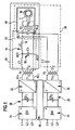
- a first embodiment of a device according to the invention for inductive heating of a workpiece W comprises, as shown in Fig. 1, an inductive load branch 10, in which an induction coil I arranged is, with which the workpiece W inductively heated, in particular hardened, can be.
- the induction coil I is connected via a transformer T2 to load terminals AL1 and AL2, in such a way that a primary winding T3 1 is electrically connected directly to the load terminals AL1 and AL2, while a secondary winding T3 2 of the transformer T3 electrically directly to the induction coil I. connected is.
- Parallel to the inductive load branch 10 is located between the load terminals AL1 and AL2 a coupling branch 12, which together with the load branch 10 a first resonant circuit 20 forms.
- the coupling branch 12 of the first resonant circuit 20 comprises a capacitance C1 between terminals AC1 and AC2, which is between the terminals AL1 and AL2 is connected in parallel to the load branch 10, wherein preferably between one of the terminals AC1 or AC2 and the corresponding one Load connection AL1 or AL2 one in detail below explanatory Drosselinduktsammlung L2 is provided.
- the terminal AC1 or AC2 of the coupling branch 12 is still connected via a coupling inductance L1 to a transformer T1, with a secondary winding T1 2 thereof, while a primary winding T1 1 of the transformer T1 connected to outputs A1 1 and A2 1 of a first inverter 22 is, which is supplied with DC voltage from a first rectifier 24 via a voltage intermediate circuit 26, wherein in the voltage intermediate circuit 26 between the first rectifier 24 and the first inverter 22, a capacitor CG 1 is still provided, which serves to effect AC voltages at the frequency of the first inverter 22 to suppress the supply network for the first rectifier 24.
- the inverter 22 is a following in detail yet explanatory so-called inverter with voltage intermediate circuit, which operates to resonate the first resonant circuit 20.
- the first resonant circuit 20 of the illustrated first embodiment may be referred to as L-LC resonant circuit.
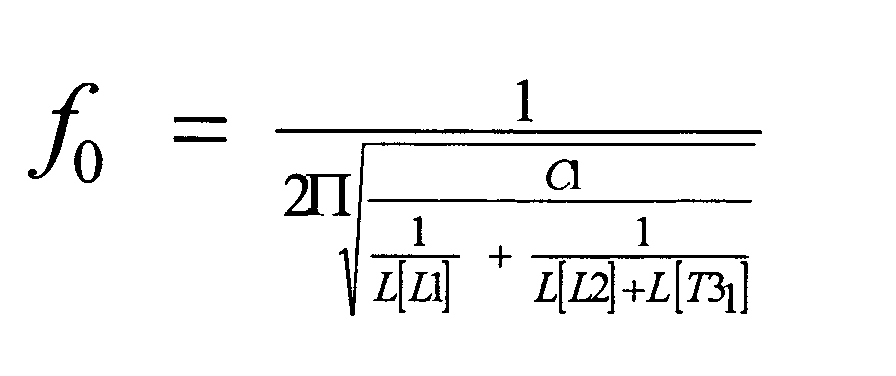
- the resonant frequency of this L-LC resonant circuit 20 is determined by the inductance values L [L1], L [L2] of the inductances L1, L2 and the inductance value L [T3 1 ] of the primary winding T3 1 as well as the capacitance C1.
- This L-LC oscillation circuit 20 has a resonance frequency f 0 which is set as follows
- Such a parallel resonant circuit 14 would have a resonant frequency f RP wherein the resonant frequency f RP determining inductance of this parallel resonant circuit 14 is to be formed from the sum of the inductance values L [L2] and L [T3 1 ].
- This resonant frequency f RP is lower than the resonant frequency f 0 of the first resonant circuit 20.
- the first inverter 22 preferably operates in a range of 1 kHz to 500 kHz, especially at a so-called center frequency.
- a second resonant circuit 30, preferably a series resonant circuit is provided, which is formed by a capacitor C2 and the inductive Load branch 10, wherein the capacitor C2 is connected in series with the primary winding T3 1 of the transformer T3 and, for example, in the connection between the first load terminal AL1 and a secondary winding T2 2 of a transformer T2, while the secondary winding T2 2 also directly to the second load terminal AL2 connected is.
- the transformer T2 is connected with its primary winding T2 1 to an output side of a second inverter 32, which is supplied via a second rectifier 34 with DC voltage.
- This second inverter 32 also operates as a voltage-controlled inverter and generates an alternating current at a resonant frequency f RS of the series resonant circuit 30, which results as follows
- the inductive load branch 10 in particular via the primary winding T3 1 of the transformer T3, represents the inductance connected in series with the capacitor C2, the primary winding T3 1 being connected in parallel with the inductance L2.
- the second resonant frequency f RS is higher than the first resonant frequency f 0 and preferably at frequencies in the range of 5 kHz to 3 MHz.
- both the first, the parallel resonant circuit 14 comprehensive resonant circuit 20 and the second designed as a resonant circuit resonant circuit 30 each include the same inductive load branch 10 as inductance, neither the first resonant frequency f 0 nor the second resonant frequency f RS to interference with each not of these second and first inverters 32 and 22, for the following reasons:
- the load branch 12 initially comprises a damping branch 16, which in the illustrated embodiment is formed by the inductance inductor L2, and subsequently to this Damping branch 16 a Quasicurzschlußzweig 18, which is formed in the illustrated embodiment by the capacitor C1.
- the reactor inductance L2 is dimensioned such that it reduces the coupling of an alternating current of the second frequency f RS into the first inverter 22, since an alternating current of the frequency f RS in the coupling branch 12 is damped by the inductance inductor L2.
- the inductance inductor L2 if the inductance value L [L2] is at least three times greater than the inductance value L [T3 1 ] of the primary winding T3 1 of the transformer T3, so that thereby only a small alternating current at the terminal AC 1 of the capacitor C1 with the second resonance frequency f RS sets.
- the quasi-short-circuit branch 18 in the coupling branch 12 which is formed by the capacitance C1 in the illustrated embodiment, leads to a short circuit for an alternating current of the second frequency f RS so that a further suppression of the formation of an alternating current of the second frequency f RS in the coupling branch 12 takes place ,
- the inductance value L [L1] of the coupling inductance L1 is preferably approximately three times as large as the sum of the inductance values L [L2] and L [T3 1 ] of the inductance L2 and of the primary winding T3 1 .
- the first inverter 22 operates substantially unaffected by AC voltage of the second resonant frequency f RS .
- the device according to the invention for inductive heating of workpieces W still comprises a total control 40, with which there is the possibility of the first inverter 22 and the second inverter 32 with respect to their performance relative to each other in a wide range, preferably in a ratio of 1:99 to to control to a ratio of 99: 1 to operate depending on the application, the induction coil I with AC of the first resonant frequency f 0 and AC of the second resonant frequency f RS , each with different levels of power and to act on the workpiece W with the appropriate fields.
- the first rectifier 24 is preferably a six-pulse bridge rectifier for a Drehstomnetz, at higher powers, however, higher pulse, executed and generates, for example, a DC voltage of 540 V in the voltage intermediate circuit 26th
- the first inverter 22 is fed, which is designed as a full bridge circuit and switching transistors V1 1 , V2 1 , V3 1 and V4 1 , which freewheeling diodes D1 1 , D2 1 , D3 1 and D4 1 are assigned in antiparallel.
- the individual switching transistors V1 1 to V4 1 can also consist of several parallel-connected individual transistors with corresponding freewheeling diodes.
- the switching transistors V1 1 to V4 1 are driven by a first inverter controller 50, which operates the switching transistors V1 1 to V4 1 so that outputs A1 1 and A2 1 of the first inverter 22 alternately with the plus input and the minus input of first inverter 22 are connected to produce the approximately rectangular AC voltage Ua 1 shown in FIG. 4 and the resulting corresponding AC current Ia 1 .
- the periodicity of the AC voltage Ua 1 corresponds to the resonant frequency f 0 of the L-LC resonant circuit 24, wherein the first inverter controller 50 for this purpose to drive the switching transistors V1 1 to V4 1 detects the current Ia 1 at the output of the first inverter 22 and a PLL Circuit determines the time sequence of the control for the switching transistors V1 1 to V4 1 in adaptation to the time course of the current Ia 1 .
- the first inverter 22 always operates at the resonant frequency f 0 of the first resonant circuit 20, it is possible to turn on the switching transistors V1 1 to V4 1 at least with low loss while switching off in dependence on the set pulse width is lossy. Nevertheless, the losses to be accepted are minimized as far as possible.
- the second rectifier 34 and the second inverter 32 are constructed in principle in the same way and work with a voltage intermediate circuit 36, as the first inverter 22, the switching transistors V1 2 to V4 2 are controlled by a second inverter control 60, in contrast to first inverter controller 50 according to the control principle of the "pulse packet control" works.
- the second inverter controller 60 detects the current Ia 2 at the outputs A1 2 or A2 2 and synchronizes the time sequence of driving the switching transistors V1 2 to V4 2 by means of a known PLL circuit, so that the switching transistors V1 2 to V4 2 time synchronous to the second resonant frequency f RS switch.
- the switching transistors V1 2 to V2 4 are always switched on essentially at the zero crossing of the current Ia 2 .
- pulse packets 62 are formed, which are at least essentially half the period of the time profile of the current Ia 2 and after these pulse packets 62 is interrupted until the next pulse packet 62, so that in each case the voltage Ua 2 near the, is turned on and off substantially at the zero crossing of the current Ia 2 .
- a pulse packet control is carried out in which the power of the second inverter 32 is to correspond to an effective value of the voltage of 50%, then the voltage Ua 2 is switched on during a positive and a subsequent negative half cycle of the current Ia 2 ', then during the next positive one and negative half-wave off, then off again during a positive and a subsequent negative half cycle, and so on, with the amplitude of the current Ia 2 'decaying after such a pulse packet 62 and then increasing again in the next pulse packet 62.
- a pulse packet control is performed with a power of the second inverter 32 which corresponds to an effective value of the voltage of 20%.
- the voltage Ua 2 switched by the switching transistors V1 2 to V4 2 and then turned off, for example, during the next eight half-waves, so that after this pulse packet 62 of the current Ia second "decreases in amplitude and only at the next pulse packet 62 again reaches the maximum amplitude and decays after this again.
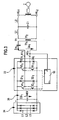
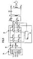
- the first resonant circuit 20 ' is formed so that the coupling branch 12' in addition to the coupling inductance L1 still has a coupling capacitance C3, which is connected in series with the coupling inductance L1 and not only serves to decouple the first inverter 22 and the second inverter 32 DC, but also affects the resonant frequency f 0 of the first resonant circuit 20 at the same time.
- the second embodiment is formed in the same way as the first embodiment, so that fully to the statements Reference may be made to the first embodiment.
Landscapes
- Chemical & Material Sciences (AREA)
- Engineering & Computer Science (AREA)
- Materials Engineering (AREA)
- Thermal Sciences (AREA)
- Crystallography & Structural Chemistry (AREA)
- Mechanical Engineering (AREA)
- Physics & Mathematics (AREA)
- Metallurgy (AREA)
- Organic Chemistry (AREA)
- General Induction Heating (AREA)
- Inverter Devices (AREA)
- Lining Or Joining Of Plastics Or The Like (AREA)
- Heating, Cooling, Or Curing Plastics Or The Like In General (AREA)
- Manufacturing Of Electric Cables (AREA)
Abstract
Description
- Fig. 1
- eine schematische Darstellung eines ersten Ausführungsbeispiels einer erfindungsgemäßen Einrichtung;
- Fig. 2
- eine vergrößerte perspektivische Darstellung einer Induktionsspule des in Fig. 1 dargestellten Ausführungsbeispiels und der Wechselspannung, die an dieser Induktionsspule anliegt;
- Fig. 3
- eine schematische vergrößerte Darstellung eines ersten Gleichrichters, eines ersten Wechselrichters mit dem ersten Schwingkreis;
- Fig. 4
- eine schematische Darstellung des Verlaufs der von dem ersten Wechselrichter erzeugten Spannung und des entsprechenden Stroms;
- Fig. 5
- eine schematische Darstellung des zweiten Gleichrichters, des zweiten Wechselrichters und des zweiten Schwingkreises;
- Fig. 6
- eine Darstellung des zeitlichen Verlaufs der vom zweiten Wechselrichter erzeugten Spannung und des vom zweiten Wechselrichter erzeugten Stroms bei 100 %-iger Modulation;
- Fig. 7
- eine schematische Darstellung des Verlaufs der Spannung und des Stroms ähnlich Fig. 6 bei einer 50 %-igen Modulation;
- Fig. 8
- eine schematische Darstellung des Verlaufs der Spannung und des Stroms ähnlich Fig. 6 bei einer Modulation von 20 % und
- Fig. 9.
- eine schematische Darstellung eines zweiten Ausführungsbeispiels einer erfindungsgemäßen Einrichtung ähnlich Fig. 1.


Claims (27)
- Einrichtung zum induktiven Erwärmen von Werkstücken (W) mittels einer Induktionsspule (I), insbesondere zum Härten der Werkstücke (W), umfassend
einen durch einen ersten Wechselrichter (22) betriebenen ersten Schwingkreis (20), der für eine erste Frequenz (f0) als Resonanzfrequenz ausgebildet ist,
einen durch einen spannungsgesteuerten zweiten Wechselrichter (32) betriebenen zweiten Schwingkreis (30), der für eine zweite Frequenz (fRS) als Resonanzfrequenz ausgebildet ist, wobei die zweite Frequenz (fRS) höher liegt als die erste Frequenz (f0),
und einen die Induktionsspule (I) umfassenden induktiven Lastzweig (10) mit Lastanschlüssen (AL1, AL2), welcher über die Lastanschlüsse (AL1, AL2) sowohl in den ersten Schwingkreis (20) als auch in den zweiten Schwingkreis (30) eingebunden und sowohl im ersten Schwingkreis (20) als auch im zweiten Schwingkreis (20) als Induktivität miteinbezogen ist,
dadurch gekennzeichnet, daß der erste Wechselrichter als Wechselrichter (22) mit Spannungszwischenkreis ausgebildet ist und daß der erste Schwingkreis (20) eine Kopplungsinduktivität (L1) umfaßt, über welche dieser mit dem ersten Wechselrichter (22) gekoppelt ist. - Einrichtung nach Anspruch 1, dadurch gekennzeichnet, daß der erste Schwingkreis (20) einen parallel zum Lastzweig (10) geschalteten und mit diesem über die Lastanschlüsse (AL1, AL2) verbundenen Kopplungszweig (12) umfaßt, in welchem die Kopplungsinduktivität (L1) angeordnet ist und welcher Rückwirkungen von Wechselspannungen der zweiten Frequenz (fRS) auf den ersten Wechselrichter (22) dämpft.
- Einrichtung nach Anspruch 2, dadurch gekennzeichnet, daß der Kopplungszweig (12) einen Quasikurzschlußzweig (18) für Wechselspannungen der zweiten Frequenz (fRS) aufweist.
- Einrichtung nach Anspruch 3, dadurch gekennzeichnet, daß der Quasikurzschlußzweig (18) über einen Dämpfungszweig (16) für Wechselspannungen der zweiten Frequenz (fRS) an die Lastanschlüsse (AL1, AL2) gekoppelt ist.
- Einrichtung nach Anspruch 4, dadurch gekennzeichnet, daß der Dämpfungszweig (16) eine Drosselinduktivität (L2) umfaßt.
- Einrichtung nach einem der Ansprüche 3 bis 5, dadurch gekennzeichnet, daß der Quasikurzschlußzweig (14) über die Kopplungsinduktivität (L1) mit dem ersten Wechselrichter (22) gekoppelt ist.
- Einrichtung nach einem der Ansprüche 3 bis 6, dadurch gekennzeichnet, daß der Quasikurzschlußzweig (14) eine Kapazität (C1) umfaßt.
- Einrichtung nach einem der voranstehenden Ansprüche, dadurch gekennzeichnet, daß der erste Schwingkreis (20) vom ersten Wechselrichter (22) bei der ersten Frequenz (f0) betrieben wird.
- Einrichtung nach einem der voranstehenden Ansprüche, dadurch gekennzeichnet, daß der erste Schwingkreis (20) zusätzlich zur Kopplungsinduktivität (L1) einen Parallelschwingkreis (14) umfaßt.
- Einrichtung nach Anspruch 9, dadurch gekennzeichnet, daß der Parallelschwingkreis (14) eine Resonanzfrequenz (fRP) aufweist, die von der Resonanzfrequenz (f0) des ersten Schwingkreises (20) abweicht.
- Einrichtung nach einem der voranstehenden Ansprüche, dadurch gekennzeichnet, daß der erste Schwingkreis (20') eine Kopplungskapazität (C3) aufweist.
- Einrichtung nach Anspruch 11, dadurch gekennzeichnet, daß die Kopplungskapazität (C3) und die Kopplungsinduktivität (L1) in Serie geschaltet sind.
- Einrichtung nach Anspruch 11 oder 12, dadurch gekennzeichnet, daß die Kopplungsinduktivität (L1) und die Kopplungskapazität (C3) in dem Kopplungszweig (12) zwischen dem Quasikurzschlußzweig (18) und dem ersten Wechselrichter (22) liegen.
- Einrichtung nach einem der voranstehenden Ansprüche, dadurch gekennzeichnet, daß der zweite Schwingkreis (30) ein Serienschwingkreis ist.
- Einrichtung nach einem der voranstehenden Ansprüche, dadurch gekennzeichnet, daß dem ersten Wechselrichter (22) eine erste Wechselrichtersteuerung (50) als Leistungssteuerung zugeordnet ist.
- Einrichtung nach Anspruch 15, dadurch gekennzeichnet, daß die erste Wechselrichtersteuerung (50) die Leistung des ersten Wechselrichters (22) durch Pulsweitenmodulation steuert.
- Einrichtung nach einem der voranstehenden Ansprüche, dadurch gekennzeichnet, daß dem zweiten Wechselrichter (32) eine zweite Wechselrichtersteuerung (60) als Leistungssteuerung zugeordnet ist.
- Einrichtung nach Anspruch 17, dadurch gekennzeichnet, daß die zweite Wechselrichtersteuerung (60) die Leistung des zweiten Wechselrichters (32) durch Pulspaketsteuerung steuert.
- Einrichtung nach einem der Ansprüche 15 bis 16, dadurch gekennzeichnet, daß die Einrichtung eine Gesamtsteuerung (40) aufweist, welche mit der ersten und zweiten Wechselrichtersteuerung (50, 60) gekoppelt ist und mit welcher die Leistung des ersten Wechselrichters (22) und die Leistung des zweiten Wechselrichters (32) unterschiedlich einstellbar sind.
- Einrichtung nach Anspruch 19, dadurch gekennzeichnet, daß mit der Gesamtsteuerung (40) die Leistung des ersten Wechselrichters (22) und die Leistung des zweiten Wechselrichters (32) jeweils im wesentlichen stufenlos einstellbar sind.
- Einrichtung nach Anspruch 19 oder 20, dadurch gekennzeichnet, daß die Leistung des ersten Wechselrichters (22) relativ zur Leistung des zweiten Wechselrichters (32) mindestens in einem Bereich, der von einem Verhältnis von 40:60 bis zu einem Verhältnis von 60:40 reicht, einstellbar sind.
- Einrichtung nach einem der voranstehenden Ansprüche, dadurch gekennzeichnet, daß sich die erste Frequenz (fRP) und die zweite Frequenz (fRS) um mindestens eine halbe Dekade unterscheiden.
- Einrichtung nach einem der voranstehenden Ansprüche, dadurch gekennzeichnet, daß die erste Frequenz (f0) im Bereich von 1 kHz bis 500 kHz liegt.
- Einrichtung nach einem der voranstehenden Ansprüche, dadurch gekennzeichnet, daß die zweite Frequenz (fRS) in einem Bereich von 5 kHz bis 3 MHz liegt.
- Einrichtung nach einem der voranstehenden Ansprüche, dadurch gekennzeichnet, daß die Kopplungsinduktivität (L1) des ersten Schwingkreises (20) einen Induktivitätswert aufweist, die mindestens das Dreifache der Summe der Induktivitätswerte der übrigen Induktivitäten (L1, T31) im ersten Schwingkreis beträgt.
- Einrichtung nach einem der Ansprüche 3 bis 25, dadurch gekennzeichnet, daß die im Kopplungszweig zwischen dem Lastanschluß (AL1) und dem Quasikurzschlußzweig (C1) liegende Drosselinduktivität (L2) einen Induktivitätswert aufweist, der mindestens dreimal größer als der im ersten Schwingkreis (20) wirksame Induktivitätswert L[T31] des Lastkreises (10) ist.
- Einrichtung nach einem der voranstehenden Ansprüche, dadurch gekennzeichnet, daß im Lastkreis (10) zwischen den Lastanschlüssen (AL1, AL2) und der Induktionsspule (I) ein Transformator (T3) vorgesehen ist.
Priority Applications (1)
| Application Number | Priority Date | Filing Date | Title |
|---|---|---|---|
| SI200330392T SI1363474T1 (sl) | 2002-05-16 | 2003-04-16 | Naprava za indukcijsko segrevanje obdelovancev |
Applications Claiming Priority (2)
| Application Number | Priority Date | Filing Date | Title |
|---|---|---|---|
| DE10223152A DE10223152A1 (de) | 2002-05-16 | 2002-05-16 | Einrichtung zum induktiven Erwärmen von Werkstücken |
| DE10223152 | 2002-05-16 |
Publications (3)
| Publication Number | Publication Date |
|---|---|
| EP1363474A2 true EP1363474A2 (de) | 2003-11-19 |
| EP1363474A3 EP1363474A3 (de) | 2004-09-15 |
| EP1363474B1 EP1363474B1 (de) | 2006-05-31 |
Family
ID=29265386
Family Applications (1)
| Application Number | Title | Priority Date | Filing Date |
|---|---|---|---|
| EP03008680A Expired - Lifetime EP1363474B1 (de) | 2002-05-16 | 2003-04-16 | Einrichtung zum induktiven Erwärmen von Werkstücken |
Country Status (7)
| Country | Link |
|---|---|
| EP (1) | EP1363474B1 (de) |
| AT (1) | ATE328462T1 (de) |
| DE (2) | DE10223152A1 (de) |
| DK (1) | DK1363474T3 (de) |
| ES (1) | ES2263871T3 (de) |
| PT (1) | PT1363474E (de) |
| SI (1) | SI1363474T1 (de) |
Cited By (13)
| Publication number | Priority date | Publication date | Assignee | Title |
|---|---|---|---|---|
| ES2289866A1 (es) * | 2005-06-07 | 2008-02-01 | Gh Electrotermia, S.A. | Equipo compuesto de dos convertidores con salida bifrecuencial simultanea para calentamiento por induccion. |
| EP2148421A1 (de) * | 2008-07-21 | 2010-01-27 | GH Electrotermia, S.A. | Pulsdauermodulierter umrichter für induktionswärme mit hohem wirkungsgrad |
| EP2148551A1 (de) | 2008-07-21 | 2010-01-27 | GH Electrotermia, S.A. | Vorrichtung zur induktiven Erwärmung mit einem einzelnen Wechselrichter auf Basis von Siliziumkarbid und einem verschiedenfrequente Ausgangsströme überlagernden Resonanzkreis |
| EP2147983A1 (de) | 2008-07-21 | 2010-01-27 | GH Electrotermia, S.A. | Vorrichtung zur induktiven Erwärmung mit einem Gleichrichter, mindestens zwei Wechselrichtern und einem verschiedenfrequente Ausgangsströme überlagernden Resonanzkreis |
| DE102013100154A1 (de) | 2013-01-09 | 2014-07-10 | Eldec Schwenk Induction Gmbh | Verfahren zum Erwärmen von Werkstücken auf Härtetemperatur |
| US20160113068A1 (en) * | 2014-10-21 | 2016-04-21 | Ultraflex International, Inc. | Radio frequency heating apparatus using direct-digital radio frequency power control and fine-tune power control |
| CN110190755A (zh) * | 2019-04-16 | 2019-08-30 | 苏州振吴电炉有限公司 | 一种双线圈输出的感应加热电源电路 |
| WO2019245663A1 (en) * | 2018-06-18 | 2019-12-26 | Ultraflex International, Inc. | Radio frequency heating apparatus using direct-digital radio frequency power control and fine-tune power control |
| KR20200077491A (ko) * | 2019-03-05 | 2020-06-30 | 인투코어테크놀로지 주식회사 | 전원 공급 장치 |
| EP3644490A4 (de) * | 2017-06-23 | 2021-03-10 | En2Core Technology, Inc | Stromversorgungsvorrichtung und verfahren zur versorgung einer last mit strom |
| WO2021074464A1 (es) | 2019-10-17 | 2021-04-22 | Gh Electrotermia, S.A. | Sistema para calentamiento por inducción de piezas metálicas |
| US11051369B2 (en) | 2014-10-21 | 2021-06-29 | Ultraflex International, Inc. | Radio frequency heating apparatus using direct-digital radio frequency power control and fine-tune power control |
| KR20230041992A (ko) * | 2020-06-22 | 2023-03-27 | 인투코어테크놀로지 주식회사 | 전원 공급 장치 |
Families Citing this family (2)
| Publication number | Priority date | Publication date | Assignee | Title |
|---|---|---|---|---|
| DE102010028057A1 (de) * | 2010-04-21 | 2011-10-27 | Maschinenfabrik Alfing Kessler Gmbh | Induktionsheizmodul |
| CN113784470B (zh) * | 2021-08-31 | 2023-07-25 | 河北工业大学 | 一种基于llc的感应加热系统 |
Family Cites Families (5)
| Publication number | Priority date | Publication date | Assignee | Title |
|---|---|---|---|---|
| US1852215A (en) * | 1928-10-16 | 1932-04-05 | Ajax Electrothermic Corp | Inductor type furnace |
| JP2530812B2 (ja) * | 1985-12-12 | 1996-09-04 | 富士電機株式会社 | 高周波誘導加熱装置 |
| DE4011612A1 (de) * | 1990-04-10 | 1991-10-17 | Elva Induksjon As | Verfahren und einrichtung zur oberflaechenhaertung rotationssymmetrischer teile durch induktive erwaermung mit hilfe wenigstens zweier unterschiedlicher frequenzen |
| DE19527827C2 (de) * | 1995-07-29 | 1998-02-12 | Kuka Schweissanlagen & Roboter | Verfahren und Einrichtung zur Erzeugung elektrischer Wärme |
| DE19637561C1 (de) * | 1996-09-14 | 1998-02-26 | Dienes Apparatebau Gmbh | Fühlerlose Temperaturregelung einer Heizvorrichtung |
-
2002
- 2002-05-16 DE DE10223152A patent/DE10223152A1/de not_active Withdrawn
-
2003
- 2003-04-16 SI SI200330392T patent/SI1363474T1/sl unknown
- 2003-04-16 DK DK03008680T patent/DK1363474T3/da active
- 2003-04-16 AT AT03008680T patent/ATE328462T1/de active
- 2003-04-16 PT PT03008680T patent/PT1363474E/pt unknown
- 2003-04-16 EP EP03008680A patent/EP1363474B1/de not_active Expired - Lifetime
- 2003-04-16 DE DE50303546T patent/DE50303546D1/de not_active Expired - Lifetime
- 2003-04-16 ES ES03008680T patent/ES2263871T3/es not_active Expired - Lifetime
Cited By (23)
| Publication number | Priority date | Publication date | Assignee | Title |
|---|---|---|---|---|
| ES2289866A1 (es) * | 2005-06-07 | 2008-02-01 | Gh Electrotermia, S.A. | Equipo compuesto de dos convertidores con salida bifrecuencial simultanea para calentamiento por induccion. |
| ES2289866B1 (es) * | 2005-06-07 | 2008-12-16 | Gh Electrotermia, S.A. | Equipo compuesto de dos convertidores con salida bifrecuencial simultanea para calentamiento por induccion. |
| EP2148421A1 (de) * | 2008-07-21 | 2010-01-27 | GH Electrotermia, S.A. | Pulsdauermodulierter umrichter für induktionswärme mit hohem wirkungsgrad |
| EP2148551A1 (de) | 2008-07-21 | 2010-01-27 | GH Electrotermia, S.A. | Vorrichtung zur induktiven Erwärmung mit einem einzelnen Wechselrichter auf Basis von Siliziumkarbid und einem verschiedenfrequente Ausgangsströme überlagernden Resonanzkreis |
| EP2147983A1 (de) | 2008-07-21 | 2010-01-27 | GH Electrotermia, S.A. | Vorrichtung zur induktiven Erwärmung mit einem Gleichrichter, mindestens zwei Wechselrichtern und einem verschiedenfrequente Ausgangsströme überlagernden Resonanzkreis |
| DE102013100154B4 (de) * | 2013-01-09 | 2016-06-16 | Eldec Schwenk Induction Gmbh | Verfahren zum Erwärmen von Werkstücken auf Härtetemperatur |
| DE102013100154A1 (de) | 2013-01-09 | 2014-07-10 | Eldec Schwenk Induction Gmbh | Verfahren zum Erwärmen von Werkstücken auf Härtetemperatur |
| WO2014108124A1 (de) | 2013-01-09 | 2014-07-17 | Eldec Schwenk Induction Gmbh | Verfahren zum erwärmen von werkstücken auf härtetemperatur |
| US10624158B2 (en) * | 2014-10-21 | 2020-04-14 | Ultraflex International Inc. | Radio frequency heating apparatus using direct-digital radio frequency power control and fine-tune power control |
| EP3222115A4 (de) * | 2014-10-21 | 2018-06-20 | Ultraflex Corporation OOD | Funkfrequenzheizungsvorrichtung mit direkter digitaler funkfrequenzleistungsregelung und feinabstimmungsleistungsregelung |
| US20160113068A1 (en) * | 2014-10-21 | 2016-04-21 | Ultraflex International, Inc. | Radio frequency heating apparatus using direct-digital radio frequency power control and fine-tune power control |
| US11051369B2 (en) | 2014-10-21 | 2021-06-29 | Ultraflex International, Inc. | Radio frequency heating apparatus using direct-digital radio frequency power control and fine-tune power control |
| US11632061B2 (en) | 2017-06-23 | 2023-04-18 | En2Core Technology, Inc. | Power supply and method of supplying power to load |
| EP3644490A4 (de) * | 2017-06-23 | 2021-03-10 | En2Core Technology, Inc | Stromversorgungsvorrichtung und verfahren zur versorgung einer last mit strom |
| US12155320B2 (en) | 2017-06-23 | 2024-11-26 | En2Core Technology, Inc. | Power supply and method of supplying power to load |
| US11290028B2 (en) | 2017-06-23 | 2022-03-29 | En2Core Technology, Inc. | Power supply and method of supplying power to load |
| US11909331B2 (en) | 2017-06-23 | 2024-02-20 | En2Core Technology, Inc. | Power supply and method of supplying power to load |
| WO2019245663A1 (en) * | 2018-06-18 | 2019-12-26 | Ultraflex International, Inc. | Radio frequency heating apparatus using direct-digital radio frequency power control and fine-tune power control |
| KR20200077491A (ko) * | 2019-03-05 | 2020-06-30 | 인투코어테크놀로지 주식회사 | 전원 공급 장치 |
| CN110190755A (zh) * | 2019-04-16 | 2019-08-30 | 苏州振吴电炉有限公司 | 一种双线圈输出的感应加热电源电路 |
| EP4047104A4 (de) * | 2019-10-17 | 2022-11-30 | GH Electrotermia, S.A. | System zum induktiven erwärmen von metallstücken |
| WO2021074464A1 (es) | 2019-10-17 | 2021-04-22 | Gh Electrotermia, S.A. | Sistema para calentamiento por inducción de piezas metálicas |
| KR20230041992A (ko) * | 2020-06-22 | 2023-03-27 | 인투코어테크놀로지 주식회사 | 전원 공급 장치 |
Also Published As
| Publication number | Publication date |
|---|---|
| DE10223152A1 (de) | 2003-12-18 |
| EP1363474A3 (de) | 2004-09-15 |
| PT1363474E (pt) | 2006-08-31 |
| DE50303546D1 (de) | 2006-07-06 |
| DK1363474T3 (da) | 2006-10-09 |
| EP1363474B1 (de) | 2006-05-31 |
| ATE328462T1 (de) | 2006-06-15 |
| ES2263871T3 (es) | 2006-12-16 |
| SI1363474T1 (sl) | 2006-10-31 |
Similar Documents
| Publication | Publication Date | Title |
|---|---|---|
| DE3789691T2 (de) | Schwingende Gleichrichterschaltung. | |
| EP1363474B1 (de) | Einrichtung zum induktiven Erwärmen von Werkstücken | |
| DE69602857T2 (de) | Umrichter mit einem piezoelektrischen Transformator und einer Schaltstufe deren Resonanzfrequenz verschieden von der des Transformators ist | |
| DE69216577T2 (de) | Induktionsheizgeraet | |
| EP0884830B1 (de) | Leistungsversorgungseinheit mit einem pulsdauermodulierten Wechselrichter, insbesondere für einen Röntgengenerator | |
| DE102007042771C5 (de) | Verfahren zum Betrieb der Stromversorgung einer Widerstansschweißvorrichtung | |
| DE69838991T2 (de) | Treiber für piezoelektrische motoren | |
| DE202007005779U1 (de) | MF-Plasmaleistungsgenerator | |
| DE102016125796B3 (de) | Stromrichterschaltung und verfahren zur steuerung derselben | |
| DE10393315T5 (de) | Passiver Gleichtaktfilter und Verfahren zum Betrieb eines passiven Gleichtaktfilters | |
| EP0396126A2 (de) | Vorrichtung zur Stromversorgung | |
| DE19955673A1 (de) | Leistungsversorgungseinheit mit einem Wechselrichter | |
| EP2597766A2 (de) | Bidirektionaler resonanter Wandler | |
| EP2384083A1 (de) | Schaltungsanordnung für ein Induktionskochgerät, Verfahren zum Betreiben der Schaltungsanordnung und Induktionskochgerät | |
| DE10059331A1 (de) | Verringerung von Systemeigenschwingungen bei einem an einem Umrichter mit Spannungszwischenkreis betriebenen elektrischen Motor durch periodisches Abkoppeln des Zwischenkreises vom Netz sowie korrespondierender Spannungszwischenkreis-Umrichter | |
| WO2004045068A1 (de) | Verfahren zum erzeugen einer hochfrequenten wechselspannung sowie hochfrequenz-leistungsverstärker dafür | |
| DE102014203404B4 (de) | Stromrichterschaltung und Verfahren zum Betreiben derselben | |
| DE4205599B4 (de) | Halbbrücken-Wechselrichter oder eine von einem Vollbrücken-Wechselrichter durch Halbierungsberechnung abgeleitete Schaltungsanordnung in Form eines Halbbrücken-Wechselrichters sowie Verfahren zu deren Steuerung | |
| EP2193005B1 (de) | Verfahren zum betrieb einer widerstandsschweissvorrichtung | |
| EP1267476A2 (de) | Spannungswandler | |
| DE102005031621A1 (de) | Leistungswandlervorrichtung | |
| DE3686889T2 (de) | Selbstschwingender hochfrequenzenergieumformer. | |
| DE10064213A1 (de) | Frequenzumrichtersystem mit einer Dämpfungseinrichtung mit einer passiven, statischen Impedanz zur Bedämpfung unerwünschter Resonanzschwingungen in einem durch mindestens eine eingangsseitige Induktivität und parasitäre verteilte Kapazitäten gebildeten Schwingkreis | |
| EP1081841A2 (de) | Schaltungsanordnung für einen Gleichrichter | |
| EP1174991A2 (de) | Konverter |
Legal Events
| Date | Code | Title | Description |
|---|---|---|---|
| PUAI | Public reference made under article 153(3) epc to a published international application that has entered the european phase |
Free format text: ORIGINAL CODE: 0009012 |
|
| AK | Designated contracting states |
Kind code of ref document: A2 Designated state(s): AT BE BG CH CY CZ DE DK EE ES FI FR GB GR HU IE IT LI LU MC NL PT RO SE SI SK TR |
|
| AX | Request for extension of the european patent |
Extension state: AL LT LV MK |
|
| PUAL | Search report despatched |
Free format text: ORIGINAL CODE: 0009013 |
|
| AK | Designated contracting states |
Kind code of ref document: A3 Designated state(s): AT BE BG CH CY CZ DE DK EE ES FI FR GB GR HU IE IT LI LU MC NL PT RO SE SI SK TR |
|
| AX | Request for extension of the european patent |
Extension state: AL LT LV MK |
|
| 17P | Request for examination filed |
Effective date: 20050309 |
|
| AKX | Designation fees paid |
Designated state(s): AT BE BG CH CY CZ DE DK EE ES FI FR GB GR HU IE IT LI LU MC NL PT RO SE SI SK TR |
|
| GRAP | Despatch of communication of intention to grant a patent |
Free format text: ORIGINAL CODE: EPIDOSNIGR1 |
|
| GRAS | Grant fee paid |
Free format text: ORIGINAL CODE: EPIDOSNIGR3 |
|
| GRAA | (expected) grant |
Free format text: ORIGINAL CODE: 0009210 |
|
| AK | Designated contracting states |
Kind code of ref document: B1 Designated state(s): AT BE BG CH CY CZ DE DK EE ES FI FR GB GR HU IE IT LI LU MC NL PT RO SE SI SK TR |
|
| PG25 | Lapsed in a contracting state [announced via postgrant information from national office to epo] |
Ref country code: IT Free format text: LAPSE BECAUSE OF FAILURE TO SUBMIT A TRANSLATION OF THE DESCRIPTION OR TO PAY THE FEE WITHIN THE PRESCRIBED TIME-LIMIT;WARNING: LAPSES OF ITALIAN PATENTS WITH EFFECTIVE DATE BEFORE 2007 MAY HAVE OCCURRED AT ANY TIME BEFORE 2007. THE CORRECT EFFECTIVE DATE MAY BE DIFFERENT FROM THE ONE RECORDED. Effective date: 20060531 |
|
| REG | Reference to a national code |
Ref country code: GB Ref legal event code: FG4D Free format text: NOT ENGLISH Ref country code: CH Ref legal event code: EP |
|
| REG | Reference to a national code |
Ref country code: IE Ref legal event code: FG4D Free format text: LANGUAGE OF EP DOCUMENT: GERMAN |
|
| REF | Corresponds to: |
Ref document number: 50303546 Country of ref document: DE Date of ref document: 20060706 Kind code of ref document: P |
|
| REG | Reference to a national code |
Ref country code: CH Ref legal event code: NV Representative=s name: KIRKER & CIE SA |
|
| REG | Reference to a national code |
Ref country code: RO Ref legal event code: EPE |
|
| REG | Reference to a national code |
Ref country code: PT Ref legal event code: SC4A Effective date: 20060628 |
|
| REG | Reference to a national code |
Ref country code: SE Ref legal event code: TRGR |
|
| REG | Reference to a national code |
Ref country code: GR Ref legal event code: EP Ref document number: 20060402873 Country of ref document: GR |
|
| REG | Reference to a national code |
Ref country code: DK Ref legal event code: T3 |
|
| NLR4 | Nl: receipt of corrected translation in the netherlands language at the initiative of the proprietor of the patent | ||
| REG | Reference to a national code |
Ref country code: HU Ref legal event code: AG4A Ref document number: E000725 Country of ref document: HU |
|
| GBT | Gb: translation of ep patent filed (gb section 77(6)(a)/1977) |
Effective date: 20061110 |
|
| REG | Reference to a national code |
Ref country code: ES Ref legal event code: FG2A Ref document number: 2263871 Country of ref document: ES Kind code of ref document: T3 |
|
| ET | Fr: translation filed | ||
| PLBI | Opposition filed |
Free format text: ORIGINAL CODE: 0009260 |
|
| 26 | Opposition filed |
Opponent name: EFD INDUCTION GMBH Effective date: 20070227 |
|
| PLAX | Notice of opposition and request to file observation + time limit sent |
Free format text: ORIGINAL CODE: EPIDOSNOBS2 |
|
| NLR1 | Nl: opposition has been filed with the epo |
Opponent name: EFD INDUCTION GMBH |
|
| PLAF | Information modified related to communication of a notice of opposition and request to file observations + time limit |
Free format text: ORIGINAL CODE: EPIDOSCOBS2 |
|
| PLBB | Reply of patent proprietor to notice(s) of opposition received |
Free format text: ORIGINAL CODE: EPIDOSNOBS3 |
|
| PLBP | Opposition withdrawn |
Free format text: ORIGINAL CODE: 0009264 |
|
| PG25 | Lapsed in a contracting state [announced via postgrant information from national office to epo] |
Ref country code: MC Free format text: LAPSE BECAUSE OF NON-PAYMENT OF DUE FEES Effective date: 20070430 |
|
| PG25 | Lapsed in a contracting state [announced via postgrant information from national office to epo] |
Ref country code: CY Free format text: LAPSE BECAUSE OF FAILURE TO SUBMIT A TRANSLATION OF THE DESCRIPTION OR TO PAY THE FEE WITHIN THE PRESCRIBED TIME-LIMIT Effective date: 20060531 |
|
| PLBD | Termination of opposition procedure: decision despatched |
Free format text: ORIGINAL CODE: EPIDOSNOPC1 |
|
| PGFP | Annual fee paid to national office [announced via postgrant information from national office to epo] |
Ref country code: LU Payment date: 20100429 Year of fee payment: 8 |
|
| PLBM | Termination of opposition procedure: date of legal effect published |
Free format text: ORIGINAL CODE: 0009276 |
|
| STAA | Information on the status of an ep patent application or granted ep patent |
Free format text: STATUS: OPPOSITION PROCEDURE CLOSED |
|
| PGFP | Annual fee paid to national office [announced via postgrant information from national office to epo] |
Ref country code: BG Payment date: 20100429 Year of fee payment: 8 Ref country code: IE Payment date: 20100526 Year of fee payment: 8 |
|
| 27C | Opposition proceedings terminated |
Effective date: 20100326 |
|
| PGFP | Annual fee paid to national office [announced via postgrant information from national office to epo] |
Ref country code: EE Payment date: 20100416 Year of fee payment: 8 |
|
| PGFP | Annual fee paid to national office [announced via postgrant information from national office to epo] |
Ref country code: GR Payment date: 20100429 Year of fee payment: 8 |
|
| PGFP | Annual fee paid to national office [announced via postgrant information from national office to epo] |
Ref country code: RO Payment date: 20110314 Year of fee payment: 9 |
|
| REG | Reference to a national code |
Ref country code: EE Ref legal event code: MM4A Ref document number: E000591 Country of ref document: EE Effective date: 20110430 |
|
| REG | Reference to a national code |
Ref country code: GR Ref legal event code: ML Ref document number: 20060402873 Country of ref document: GR Effective date: 20111102 |
|
| PG25 | Lapsed in a contracting state [announced via postgrant information from national office to epo] |
Ref country code: EE Free format text: LAPSE BECAUSE OF NON-PAYMENT OF DUE FEES Effective date: 20110430 |
|
| REG | Reference to a national code |
Ref country code: IE Ref legal event code: MM4A |
|
| PG25 | Lapsed in a contracting state [announced via postgrant information from national office to epo] |
Ref country code: GR Free format text: LAPSE BECAUSE OF NON-PAYMENT OF DUE FEES Effective date: 20111102 |
|
| PG25 | Lapsed in a contracting state [announced via postgrant information from national office to epo] |
Ref country code: IE Free format text: LAPSE BECAUSE OF NON-PAYMENT OF DUE FEES Effective date: 20110418 |
|
| PG25 | Lapsed in a contracting state [announced via postgrant information from national office to epo] |
Ref country code: RO Free format text: LAPSE BECAUSE OF NON-PAYMENT OF DUE FEES Effective date: 20120416 |
|
| PG25 | Lapsed in a contracting state [announced via postgrant information from national office to epo] |
Ref country code: LU Free format text: LAPSE BECAUSE OF NON-PAYMENT OF DUE FEES Effective date: 20110416 |
|
| PG25 | Lapsed in a contracting state [announced via postgrant information from national office to epo] |
Ref country code: BG Free format text: LAPSE BECAUSE OF NON-PAYMENT OF DUE FEES Effective date: 20111231 |
|
| PGFP | Annual fee paid to national office [announced via postgrant information from national office to epo] |
Ref country code: PT Payment date: 20150326 Year of fee payment: 13 |
|
| REG | Reference to a national code |
Ref country code: DE Ref legal event code: R082 Ref document number: 50303546 Country of ref document: DE Representative=s name: HOEGER, STELLRECHT & PARTNER PATENTANWAELTE MB, DE |
|
| PGFP | Annual fee paid to national office [announced via postgrant information from national office to epo] |
Ref country code: DK Payment date: 20150423 Year of fee payment: 13 |
|
| PGFP | Annual fee paid to national office [announced via postgrant information from national office to epo] |
Ref country code: NL Payment date: 20150423 Year of fee payment: 13 |
|
| PGFP | Annual fee paid to national office [announced via postgrant information from national office to epo] |
Ref country code: BE Payment date: 20150423 Year of fee payment: 13 |
|
| REG | Reference to a national code |
Ref country code: FR Ref legal event code: PLFP Year of fee payment: 14 |
|
| PG25 | Lapsed in a contracting state [announced via postgrant information from national office to epo] |
Ref country code: BE Free format text: LAPSE BECAUSE OF NON-PAYMENT OF DUE FEES Effective date: 20160430 |
|
| REG | Reference to a national code |
Ref country code: DK Ref legal event code: EBP Effective date: 20160430 |
|
| REG | Reference to a national code |
Ref country code: NL Ref legal event code: MM Effective date: 20160501 |
|
| PG25 | Lapsed in a contracting state [announced via postgrant information from national office to epo] |
Ref country code: NL Free format text: LAPSE BECAUSE OF NON-PAYMENT OF DUE FEES Effective date: 20160501 |
|
| PG25 | Lapsed in a contracting state [announced via postgrant information from national office to epo] |
Ref country code: PT Free format text: LAPSE BECAUSE OF NON-PAYMENT OF DUE FEES Effective date: 20161017 |
|
| REG | Reference to a national code |
Ref country code: FR Ref legal event code: PLFP Year of fee payment: 15 |
|
| PG25 | Lapsed in a contracting state [announced via postgrant information from national office to epo] |
Ref country code: DK Free format text: LAPSE BECAUSE OF NON-PAYMENT OF DUE FEES Effective date: 20160430 |
|
| REG | Reference to a national code |
Ref country code: FR Ref legal event code: PLFP Year of fee payment: 16 |
|
| REG | Reference to a national code |
Ref country code: DE Ref legal event code: R082 Ref document number: 50303546 Country of ref document: DE Representative=s name: HOEGER, STELLRECHT & PARTNER PATENTANWAELTE MB, DE |
|
| PGFP | Annual fee paid to national office [announced via postgrant information from national office to epo] |
Ref country code: FI Payment date: 20200428 Year of fee payment: 18 Ref country code: CH Payment date: 20200423 Year of fee payment: 18 Ref country code: CZ Payment date: 20200409 Year of fee payment: 18 |
|
| PGFP | Annual fee paid to national office [announced via postgrant information from national office to epo] |
Ref country code: HU Payment date: 20200422 Year of fee payment: 18 Ref country code: GB Payment date: 20200424 Year of fee payment: 18 Ref country code: SK Payment date: 20200408 Year of fee payment: 18 Ref country code: SE Payment date: 20200424 Year of fee payment: 18 Ref country code: SI Payment date: 20200414 Year of fee payment: 18 |
|
| PGFP | Annual fee paid to national office [announced via postgrant information from national office to epo] |
Ref country code: AT Payment date: 20200423 Year of fee payment: 18 |
|
| PGFP | Annual fee paid to national office [announced via postgrant information from national office to epo] |
Ref country code: FR Payment date: 20210424 Year of fee payment: 19 Ref country code: IT Payment date: 20210430 Year of fee payment: 19 |
|
| PGFP | Annual fee paid to national office [announced via postgrant information from national office to epo] |
Ref country code: TR Payment date: 20210413 Year of fee payment: 19 Ref country code: ES Payment date: 20210504 Year of fee payment: 19 |
|
| REG | Reference to a national code |
Ref country code: FI Ref legal event code: MAE |
|
| REG | Reference to a national code |
Ref country code: SE Ref legal event code: EUG |
|
| REG | Reference to a national code |
Ref country code: AT Ref legal event code: MM01 Ref document number: 328462 Country of ref document: AT Kind code of ref document: T Effective date: 20210416 |
|
| REG | Reference to a national code |
Ref country code: SK Ref legal event code: MM4A Ref document number: E 886 Country of ref document: SK Effective date: 20210416 |
|
| GBPC | Gb: european patent ceased through non-payment of renewal fee |
Effective date: 20210416 |
|
| PG25 | Lapsed in a contracting state [announced via postgrant information from national office to epo] |
Ref country code: SE Free format text: LAPSE BECAUSE OF NON-PAYMENT OF DUE FEES Effective date: 20210417 Ref country code: SK Free format text: LAPSE BECAUSE OF NON-PAYMENT OF DUE FEES Effective date: 20210416 Ref country code: CZ Free format text: LAPSE BECAUSE OF NON-PAYMENT OF DUE FEES Effective date: 20210416 Ref country code: HU Free format text: LAPSE BECAUSE OF NON-PAYMENT OF DUE FEES Effective date: 20210417 Ref country code: GB Free format text: LAPSE BECAUSE OF NON-PAYMENT OF DUE FEES Effective date: 20210416 Ref country code: FI Free format text: LAPSE BECAUSE OF NON-PAYMENT OF DUE FEES Effective date: 20210416 Ref country code: LI Free format text: LAPSE BECAUSE OF NON-PAYMENT OF DUE FEES Effective date: 20210430 Ref country code: AT Free format text: LAPSE BECAUSE OF NON-PAYMENT OF DUE FEES Effective date: 20210416 Ref country code: CH Free format text: LAPSE BECAUSE OF NON-PAYMENT OF DUE FEES Effective date: 20210430 |
|
| PG25 | Lapsed in a contracting state [announced via postgrant information from national office to epo] |
Ref country code: SI Free format text: LAPSE BECAUSE OF NON-PAYMENT OF DUE FEES Effective date: 20210417 |
|
| REG | Reference to a national code |
Ref country code: SI Ref legal event code: KO00 Effective date: 20220201 |
|
| PGFP | Annual fee paid to national office [announced via postgrant information from national office to epo] |
Ref country code: DE Payment date: 20220629 Year of fee payment: 20 |
|
| PG25 | Lapsed in a contracting state [announced via postgrant information from national office to epo] |
Ref country code: FR Free format text: LAPSE BECAUSE OF NON-PAYMENT OF DUE FEES Effective date: 20220430 |
|
| REG | Reference to a national code |
Ref country code: DE Ref legal event code: R071 Ref document number: 50303546 Country of ref document: DE |
|
| REG | Reference to a national code |
Ref country code: ES Ref legal event code: FD2A Effective date: 20230529 |
|
| PG25 | Lapsed in a contracting state [announced via postgrant information from national office to epo] |
Ref country code: IT Free format text: LAPSE BECAUSE OF NON-PAYMENT OF DUE FEES Effective date: 20220416 |
|
| PG25 | Lapsed in a contracting state [announced via postgrant information from national office to epo] |
Ref country code: ES Free format text: LAPSE BECAUSE OF NON-PAYMENT OF DUE FEES Effective date: 20220417 |