EP1363379A2 - Module de puissance pour générer des impulsions à des niveaux différents - Google Patents
Module de puissance pour générer des impulsions à des niveaux différents Download PDFInfo
- Publication number
- EP1363379A2 EP1363379A2 EP03006939A EP03006939A EP1363379A2 EP 1363379 A2 EP1363379 A2 EP 1363379A2 EP 03006939 A EP03006939 A EP 03006939A EP 03006939 A EP03006939 A EP 03006939A EP 1363379 A2 EP1363379 A2 EP 1363379A2
- Authority
- EP
- European Patent Office
- Prior art keywords
- electrically coupled
- power module
- switching element
- voltage source
- power
- Prior art date
- Legal status (The legal status is an assumption and is not a legal conclusion. Google has not performed a legal analysis and makes no representation as to the accuracy of the status listed.)
- Withdrawn
Links
Images

Classifications
-
- H—ELECTRICITY
- H02—GENERATION; CONVERSION OR DISTRIBUTION OF ELECTRIC POWER
- H02J—CIRCUIT ARRANGEMENTS OR SYSTEMS FOR SUPPLYING OR DISTRIBUTING ELECTRIC POWER; SYSTEMS FOR STORING ELECTRIC ENERGY
- H02J7/00—Circuit arrangements for charging or depolarising batteries or for supplying loads from batteries
- H02J7/0013—Circuit arrangements for charging or depolarising batteries or for supplying loads from batteries acting upon several batteries simultaneously or sequentially
- H02J7/0024—Parallel/serial switching of connection of batteries to charge or load circuit
-
- H—ELECTRICITY
- H02—GENERATION; CONVERSION OR DISTRIBUTION OF ELECTRIC POWER
- H02J—CIRCUIT ARRANGEMENTS OR SYSTEMS FOR SUPPLYING OR DISTRIBUTING ELECTRIC POWER; SYSTEMS FOR STORING ELECTRIC ENERGY
- H02J7/00—Circuit arrangements for charging or depolarising batteries or for supplying loads from batteries
- H02J7/34—Parallel operation in networks using both storage and other dc sources, e.g. providing buffering
- H02J7/345—Parallel operation in networks using both storage and other dc sources, e.g. providing buffering using capacitors as storage or buffering devices
Definitions
- the present invention relates to a DC power module. More specifically, this invention relates to a DC power module composed of a DC voltage source and supercapacitors in parallel connection for driving miscellaneous multi-functional tools with interchangeable attachments or accessories for various tasks.
- a projectile in the form of nails or staples can also be ejected at an impulse generated by either a DC or an AC power module, for example, the electric nailer powered by batteries as revealed in U.S. Pat. No.6,173,877, the battery-operated electric stapler as in U.S. Pat. Nos. 4,558,391 and 5,105,329, as well as the binding apparatus of U.S. Pat. Nos. 4,986,713; 5,818,186 and 6,086,304.
- the DC power tools have the convenience of no cord attachment and no location limitation, that is, they may be used at places away from the city power outlets, and they do not suffer voltage fluctuations as their AC counterparts often encounter.
- the DC motor driven impact has a greater stroke than an AC powered motor because, by being directly driven instead of gear driven, a more positive torque from the motor to a striking piston is created for the DC power tools.
- the impulse energy generated by a DC power module may be converted to an impact force for carving, chiseling, chopping, clinching, clipping, compressing, crimping, crushing, embossing, piercing, punching, splicing, and striking, etc.
- Numerous patents and commercial products for the foregoing applications are available, for example, U.S. Pat. Nos. 4,015,671; 4,468,826; 4,579,029; 4,991,472; 6,427,559 and 6,460,627 are all related to battery-operated hand-held tools. In operation, the required forces are directly transmitted from the interaction between pistons and a resilient member (such as spring ).
- the impulse provided by a DC power module may be directly delivered as a large electric current for welding as disclosed in U.S. Pat. Nos. 4,801,780 and 6,225,596.
- batteries as power source for the welders, light maintenance or urgent repair can be performed outside the availability of city electricity.
- Heavy batteries such as lead-acid (Pb-H 2 SO 4 ), environmentally hazardous batteries such as nickel-cadmium (Ni-Cd), or batteries with some memory-effect such as nickel-metal hydride (Ni-MH) are universally employed in the prior art of portable power tools driven by impulse energy.
- the batteries In order to provide sufficient impulse, the batteries are often in large sizes and in multiple numbers that makes the tools bulky and heavy.
- the electronic circuits for generating the required impulse are also complex making the tools expensive.
- the foregoing batteries are rechargeable, more often than not the batteries are too low in energy content to serve at the time of emergency. Then, the users have to wait several hours for charging the batteries for a work that may only take a few minutes to finish.
- the present invention provides a DC power module that can be custom made to deliver the desired impulse energy using a minimal amount of batteries and supercapacitors, as well as a simple electronic architecture. Furthermore, primary cells such as alkaline batteries, may be employed for the proposed power module. Power tools using the power module of the invention are compact, light, economical, and ready-to-go at all times. Using the power module of the invention in conjunction with interchangeable attachments or accessories, multi-purpose portable hand tools driven by impulse energy can be devised for various types of works.
- the portable tools that are driven by impulse can be divided into three categories:
- Tools utilize the impulse and mechanical components to launch an object such as nail, staple, or pin for fastening or binding;
- Tools utilize the impulse and mechanical components to provide an impact force for scraping, hammering, punching, embossing, chopping, chiseling, piercing, splicing or clipping;
- Tools utilize the impulse directly to deliver a surge of electricity or a peak current for starting engines, for welding metals, or for actuating machineries.
- a universal power module that consists of supercapacitors and batteries connected in parallel through a control circuit.
- Supercapacitors also know as ultracapacitors and electric double layer capacitors, are accumulators of a large quantity of static charge up to thousands of farads in a single container of small volume. Essentially, all of the charge stored in supercapacitors can be discharged at once leading to an immense current that is useful to drive many power tools. Since the supercapacitors are light and compact, the tools operated on the capacitors are truly portable. Furthermore, supercapacitors can be fabricated in various configurations at low cost, the capacitors therefore are a better device than the frequently used step-up converters, inductors or fly wheels for boosting the power output of batteries.
- the power output of any DC voltage sources, even the low-power device such as the primary batteries, can be augmented by tens of folds by the supercapaciters.
- the batteries serve as the charging source for supercapacitors, while an electronic controller will regulate the level of power output of supercapacitors via pulse width modulation (PWM).
- PWM pulse width modulation
- the batteries are arranged to always discharge at a low rate, that is, the batteries will take care all of the low-power demands, whereas the supercapacitors provide the extra power need that cannot be offered by the batteries.
- the batteries should possess an identical or comparable voltage as that of the capacitors. Often many batteries have to be placed in series to match the target of charging voltage. As the number of batteries is increased, the power module for the tools become bulky and expensive.
- the present invention imposes individual supercapacitors or supercapacitor packs in parallel connection for charging. Then, all supercapacitors are momentarily switched to series connection for discharge when an impulse is requested. By charging supercapacitors in parallel, the number and size of charging batteries may be reduced. Whereas the supercapacitors discharge through a series connection, the capacitors can impart an impulse of twice the voltage of that of the parallel configuration to the portable tools. Only a trigger and an electromeganetic relay are needed to momentarily convert the supercapacitors from parallel configuration to series formation. Not only is the electronic control architecture simple and economical, but there is virtually no energy loss at the power amplification of batteries.
- one tool body with interchangeable attachments or accessories, and the power module of the present invention may become the required all-in-one tools.
- the interchangeable attachments can be handily integrated with the tool body as described in the present invention.
- the interchangeable accessories may be provided in a supplementary kit accompanying with the tool body for various works.
- Hand-held devices of electronics and non-electronics are becoming popular and important in our daily life. Not only should the devices be compact and light for easy carry, also they should have more than one function for multiple applications. For example, some mobile phones now weigh less than 100g, and in addition to voice communication they have access to internet; further, they can also take photos as a DSC (digital still camera) with the capability of instantaneous transmission of photos through the web. As the dimension of portable devices become smaller, and as more options are added, the burden on the batteries that power the devices is heavier than ever. To cope with the inevitable modernization of the portable devices, both energy and power densities of batteries have been continuously and industriously improved. Nevertheless, the progress of battery evolution is always less than satisfaction.
- DSC digital still camera
- supercapacitors are one perfect electronic component for managing the energy operation of batteries.
- supercapacitors may serve as an energy buffer or an energy equalizer, while at the discharging of supercapacitors, the capacitors may work as a power amplifier.
- the present invention utilizes supercapacitors to amplify the power output of batteries for driving various power tools without using a converter, a transformer, a function generator or an oscillating RLC circuit.
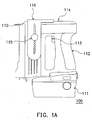
- FIG.1A shows a first embodiment of the present invention of an electric nailer 100 that is operated on an impulse energy, which is provided by a power module consisting of batteries and supercapacitors, to launch a nail or pin of various sizes for fastening.
- An object such as a nail or a pin will be ejected from the ejection port 110 of the nailer 100 upon depressing trigger 113, which causes the discharge of power module disposed inside the detachable compartment 111.
- Handle 112 provides easy grip and maneuver of the electric nailer 100 to the operators, while tool body 114 contains a number of mechanical components such as motor, gears and spring (not shown in FIG.1A). Using the impulse energy from the power module, the motor will drive or squeeze the spring to the maximum position.
- an attachment 116 with an adjusting screw 115 installed on top of the tool body 114 for conducting other function than fastening. As shown in FIG.1B, by unscrewing and resetting the screw 115, the attachment 116 can be placed and secured at a position where the clinching anvil 122 is aligned with the ejection port 110, and an electric stapler 102 is formed.
- a U-shape staple can be ejected out of the stapler 102 and through a stack of paper placed between 110 and 122 for binding (not shown in FIG. 1B). After the staple is driven through successive sheets of paper, it will be stopped in the groves of anvil 122 wherein both ends of the U-shape staple is folded against the last page of the stack to complete the binding operation.
- FIG.1B also shows a number of slots 124 on the interchangeable attachment 116 designed for adjusting the gap between 110 and 122 in corresponding to the thickness of multiple paper sheets in the stack to be bound.
- Both nailer 100 and stapler 102 not only share the same tool body 114 and the power source installed inside the compartment 111, but also nails, pins, and staples can travel through the same trajectory barrel.
- the nailer 100 and the stapler 102 are interchangeable via the attachment 116, one tool can thus perform two functions.
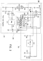
- FIG. 2 is a preferred embodiment of the present invention on the power module 200 for generating an electric impulse capable of diving power tools to launch an object, to form an impact force, and to deliver peak currents.
- Block 240 of FIG.2 is designed for instantaneously driving the aforementioned nailer 100 or stapler 102, while block 260 is for imparting large currents to heavy loads.
- supercapacitors 207 and 208, as well as relay (S1-S4) are shared by blocks 240 and 260.
- the supercapacitors 207 and 208 also know as ultracapacitors and electric double layer capacitors, are accumulators of a large quantity of static charge up to thousands of farads in a single container of small volume.
- Block 240 and 260 There is a power-level regulator within block 240 and 260 for choosing a power output to accommodate the work loads.
- a DC voltage source 201 will charge supercapacitor 207 through contacts S1a and S1, also charge supercapacitor 208 via contacts S3a and S3.
- Diode 203 is to prevent back-flow of current from the supercapacitors 207 and 208 to the DC voltage source 201.
- the aforementioned contacts (S1, S1a, S3, and S3a) are four members of 12 contacts of a 4-port electromagnetic relay with S1 to S4 as common points.
- each port of the relay has a single-pole, double-throw (SPDT) with four sets of the 12 contacts are normally closed (S1-S1a, S2-S2a,S 3-S3a, and S4-S4a), while the other four sets are normally open (S1-S1b, S2-S2b, S3-S3b, and S4-S4b).
- SPDT single-pole, double-throw
- the equal-potential capacitors 207 and 208 are connected in-parallel, thus the DC voltage source 201 may have a working voltage slightly larger than that of the capacitors, but the DC voltage source 201 may have a voltage much lower than the driving voltage of motor 209 of the impulse-driven tools. As a result, both the size and quantity of battery 201 can be reduced.
- the power-level selector 210 may fulfill the needs. There are three power levels, A, B and C, for selecting low, medium and high power outputs, respectively. The power level is determined by the resistance of the resistors 222,223 and 224, whereby the lower the resistance is, the higher the power level will be.
- the DC voltage source 201 When the switch 202 is at a1 and a1', the DC voltage source 201 will provide its voltage to the selector 210 through point a1. After the battery voltage is divided by the corresponding resistor 222, 223, or 224 and the resistor 211, a partial voltage is supplied to the non-inverting input of the differential amplifier 214. Next, by comparing the partial voltage to the internal reference voltage at the inverting input of amplifier 214, a differential voltage being amplified by a factor of the ratio between the resistances of the resistors 213 and 212 is produced as the output of 214. Subsequently, the output of 214 becomes an input voltage to the pulse width modulator (PWM) 215.
- PWM pulse width modulator
- the input voltage for 215 will be correspondingly low, medium, and high, and the resulting pulse widths generated by the PWM 215 will be narrow, medium, and wide, respectively.
- the open time of the N-channel field effect transistor (FET) 217 is decided by the triggering pulse width issued by the PWM 215.
- narrow, medium and wide pulse widths of 215 will cause short, medium and long open times, respectively, of FET 217.
- the open time of FET 217 will decide the motor 209 to receive a low, medium or high level of impulse.
- the power level control as described above may protect materials such as paper sheets from damage by excessive force.
- block 260 will be in use.
- Charging and discharging of supercapacitors 207 and 208 for block 260 are identical to that of block 240 as described above, except a switch 204 is depressed instead of the trigger 205 for driving the relay (S1-S4) and a step-up IC 219 is electrically coupled to the DC voltage source 201 and connected in parallel with the supercapacitors 207 and 208 in the mode where the supercapacitors 207 and 208 are switched into series connection via the relay (S1-S3) for discharging.
- the step-up IC 219 is employed in block 260 to boost the voltage supplied by the DC voltage source 201 ensuring the output power always at a potential level above the driving voltage of the load electrically coupled to the connector 221 before the operation is completed.
- Such supplementary power-amplification of DC voltage source 201 by step-up IC 219 serves as a backup to the supercapacitors to compensate their fast voltage drop during discharge. No matter how insignificant the power compensation is in comparison to the power output of supercapacitors, the supplemental energy may make a difference on energizing an especially heavy load such as to start the engine of an extensively idled automobile.
- the DC voltage source 201 can be, for example, primary battery, secondary battery, , fuel cells, metal-air cells, solar cells, wind cells, or rectified AC power whether they are suitable for charging the supercapacitors 207 and 208.
- a solid state relay (SSR) or a solenoid is applicable to the switching of supercapacitors as well.
- the service time and power rating of the module 200 can be custom made to meet the application requirements. By a meticulous balance between the batteries and supercapacitors incorporated in the power module 200, the module is easy to offer a specific power density well above 1 KW/Kg in compact sizes.
- Another salient feature of the present invention is that the DC voltage source 201 is always kept to discharge at a low potential level to minimize its voltage drop and to prolong its use-time, while the supercapacitors 207 and 208 are designated to supply the large power outputs that are otherwise unattainable from the DC voltage source 201.
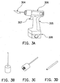
- FIG. 3 shows schematic views of an impulse-driven tool and interchangeable accessories thereof in accordance with a second embodiment of the present invention.
- the impulse-driven tool utilizes the electric impulse provided by the power module 200 of FIG. 2 to impart an impact force for various applications.
- a single tool body 306 equipped with handle 305, trigger 307, and a detachable compartment 308 that contains the power module 200 may perform as many tasks as the interchangeable accessories are available for use.
- a spade-head accessory 304 is secured by means of a set crew or other mechanisms on the driving head of tool body 306, an electric scraper 3A is formed for removing various residues from many kinds of surface.
- an electric hammer is assembled for crushing stones, or for cracking cements.
- an embossing accessory with LED inscription as shown in figure 3C may be used in corporation with the tool body 306 to construct an electric embosser for registering the letters on the surface of woods, plastics, or metals.
- Figure 3D shows a piercing accessory that may be used to build an electric puncher with piercing power controllable by the power module 200 of FIG. 2.
- the power module inside the compartment 308 will support the accessory to perform its intended function, and a multi-purpose power tool is created.
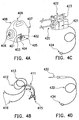
- FIG. 4 shows schematic views of a portable power supply and interchangeable accessories thereof in accordance with a third embodiment of the present invention.
- the portable power supply as shown in Figure 4A can supply peak currents utilizing the electric energy provided by the power module 200 of FIG. 2.
- the portable power supply has a housing 408 that contains the power module 200, a flash light bulb 406 on one end, and an emergency light bulb 407 on the other. Options other than illumination or signal can be installed on the power supply 4A.
- housing 408 On the surface of housing 408, there is a handle 409 for easy carry, three switches 401, 402, 403 wherein the switch 401 is the on/off control of the power module 200, the switch 403 for choosing illumination 406 or signal 407, and the switch 402 is another power on/off control for actuating the functional block 260 of FIG. 2, so that peak currents are available for heavy loads such as figures 4B to 4D. Also, there are two sockets 404 and 405 on the surface of housing 408. The socket 404 is the outlet of peak currents provided by the power module 200, while the socket 405 allows the connection to an external power source for charging the DC voltage source 201 of the power module 200.
- Figure 4B shows a car-battery jumper 411 consisting of two jumping cables 412 and 413 with male connectors 416 on one end for plugging into socket 404 to receive peak currents, and two alligator clamps 414 and 415 on the other end for connecting to the plus and negative terminals of a car battery, respectively.
- the power module 200 will provide a power with sufficient voltage and current to initiate and sustain spark ignition during cranking of the startor of combustion engine.
- figure 4C shows an electric welder accessory that can attain peak currents from the portable power supply as shown in Figure 4A via the plug 424 to energize a time and current controlling circuit installed inside the compartment 421 when the trigger 422 is actuated by a hand holding the handle 423.
- peak current pulses are supplied to the tips of electrodes 420 to cause local fusion for spot welding.
- figure 4D shows a soldering gun accessory 430 that can attain peak currents from the portable power supply as shown in Figure 4A via cable 432 and plug 434 to melt solders for constructing electronic connections in the laboratory or in the field.
- the portable power supply as shown in Figure 4A can become a portable battery jumper, a portable spot welder, and a portable soldering iron, respectively.
- a suitable accessory is available for attaching to the power outlet of the portable power supply.
- the power rating, as well as the service time, of the portable power supply is tunable by adjusting the energy capacities of both batteries and supercapacitors.
- a power module with the architecture 200 of FIG. 2 is constructed by incorporating lithium ion batteries and supercapacitors as the power module.
- the power module of the example can at least supply powers from 2.16 KW to 2.88 KW. Such large powers are unattainable from a Li battery pack of 8000 mAh. A current output of 240 A is equivalent to 30 C discharge rate of the 8000 mAh battery pack, which will cause catastrophic results if the Li ion batteries do discharge at such rate.
- the power module as constructed and its housing together weigh 1.5 Kg, and the housing has a volume of 5280 ml (150 mm x 160 mm x 220 mm).
Priority Applications (2)
| Application Number | Priority Date | Filing Date | Title |
|---|---|---|---|
| EP03006939A EP1363379A3 (fr) | 2002-05-13 | 2003-03-26 | Module de puissance pour générer des impulsions à des niveaux différents |
| JP2003164136A JP2004297992A (ja) | 2003-03-26 | 2003-06-09 | 電源モジュール |
Applications Claiming Priority (3)
| Application Number | Priority Date | Filing Date | Title |
|---|---|---|---|
| EP02010669 | 2002-05-13 | ||
| EP02010669A EP1363386B1 (fr) | 2002-05-13 | 2002-05-13 | Générateur pulsé à courant fort |
| EP03006939A EP1363379A3 (fr) | 2002-05-13 | 2003-03-26 | Module de puissance pour générer des impulsions à des niveaux différents |
Publications (2)
| Publication Number | Publication Date |
|---|---|
| EP1363379A2 true EP1363379A2 (fr) | 2003-11-19 |
| EP1363379A3 EP1363379A3 (fr) | 2004-01-02 |
Family
ID=29271886
Family Applications (1)
| Application Number | Title | Priority Date | Filing Date |
|---|---|---|---|
| EP03006939A Withdrawn EP1363379A3 (fr) | 2002-05-13 | 2003-03-26 | Module de puissance pour générer des impulsions à des niveaux différents |
Country Status (1)
| Country | Link |
|---|---|
| EP (1) | EP1363379A3 (fr) |
Cited By (5)
| Publication number | Priority date | Publication date | Assignee | Title |
|---|---|---|---|---|
| GB2449490A (en) * | 2007-05-25 | 2008-11-26 | Glory In Group Ltd | Power tool with super capacitors |
| CN102684243A (zh) * | 2011-03-18 | 2012-09-19 | 祥业科技股份有限公司 | 整合型电池充电器 |
| EP2184858A3 (fr) * | 2007-11-09 | 2012-12-05 | Linear Technology Corporation | Circuits et procédés pour réduire ou supprimer une modulation selon le signal d'une polarisation de référence |
| EP2920875A4 (fr) * | 2012-11-19 | 2016-08-03 | Dispensing Dynamics Int | Réduction de drain de courant et d'impact de pic de courant sur des dispositifs alimentés par batterie |
| EP1685637B1 (fr) | 2003-11-20 | 2016-08-17 | PELLENC (Société Anonyme) | Ensemble outil électrique portatif autonome de puissance |
Citations (10)
| Publication number | Priority date | Publication date | Assignee | Title |
|---|---|---|---|---|
| DE621927C (de) * | 1933-10-03 | 1935-11-15 | Berthold Springer | Gleichstrom-Gleichstromumformer |
| GB596337A (en) * | 1945-06-14 | 1948-01-01 | Electronic Lab Inc | Improvements in or relating to electric voltage modifying systems |
| JPH10285797A (ja) * | 1997-03-31 | 1998-10-23 | Kansai Electric Power Co Inc:The | 2重層コンデンサ充電放電回路 |
| DE29912551U1 (de) * | 1999-07-17 | 1999-10-07 | Jaekl Hans Joerg | Leistungsregler für elektrische Verbraucher |
| JPH11332013A (ja) * | 1998-05-14 | 1999-11-30 | Toyota Motor Corp | 車両駆動システム |
| WO2000019589A1 (fr) * | 1998-09-28 | 2000-04-06 | Sony Computer Entertainment Inc. | Alimentation electrique, et procede et equipement electronique associes |
| US6093982A (en) * | 1996-11-15 | 2000-07-25 | Kroll; Mark W. | High voltage output array switching system |
| EP1107420A2 (fr) * | 1999-12-03 | 2001-06-13 | Onemocall Co., Ltd | Circuit d'alimentation en tension |
| US6320274B1 (en) * | 1997-11-27 | 2001-11-20 | Siemens Ag | Onboard electrical system for a vehicle with switch connections between electrical subsystems |
| US6342775B1 (en) * | 2000-05-24 | 2002-01-29 | Brunswick Corporation | Automatic battery switching circuit for a marine propulsion system |
-
2003
- 2003-03-26 EP EP03006939A patent/EP1363379A3/fr not_active Withdrawn
Patent Citations (10)
| Publication number | Priority date | Publication date | Assignee | Title |
|---|---|---|---|---|
| DE621927C (de) * | 1933-10-03 | 1935-11-15 | Berthold Springer | Gleichstrom-Gleichstromumformer |
| GB596337A (en) * | 1945-06-14 | 1948-01-01 | Electronic Lab Inc | Improvements in or relating to electric voltage modifying systems |
| US6093982A (en) * | 1996-11-15 | 2000-07-25 | Kroll; Mark W. | High voltage output array switching system |
| JPH10285797A (ja) * | 1997-03-31 | 1998-10-23 | Kansai Electric Power Co Inc:The | 2重層コンデンサ充電放電回路 |
| US6320274B1 (en) * | 1997-11-27 | 2001-11-20 | Siemens Ag | Onboard electrical system for a vehicle with switch connections between electrical subsystems |
| JPH11332013A (ja) * | 1998-05-14 | 1999-11-30 | Toyota Motor Corp | 車両駆動システム |
| WO2000019589A1 (fr) * | 1998-09-28 | 2000-04-06 | Sony Computer Entertainment Inc. | Alimentation electrique, et procede et equipement electronique associes |
| DE29912551U1 (de) * | 1999-07-17 | 1999-10-07 | Jaekl Hans Joerg | Leistungsregler für elektrische Verbraucher |
| EP1107420A2 (fr) * | 1999-12-03 | 2001-06-13 | Onemocall Co., Ltd | Circuit d'alimentation en tension |
| US6342775B1 (en) * | 2000-05-24 | 2002-01-29 | Brunswick Corporation | Automatic battery switching circuit for a marine propulsion system |
Non-Patent Citations (2)
| Title |
|---|
| PATENT ABSTRACTS OF JAPAN vol. 1999, no. 01, 29 January 1999 (1999-01-29) & JP 10 285797 A (KANSAI ELECTRIC POWER CO INC:THE;SONODA KEIKI KOGYO KK), 23 October 1998 (1998-10-23) * |
| PATENT ABSTRACTS OF JAPAN vol. 2000, no. 02, 29 February 2000 (2000-02-29) & JP 11 332013 A (TOYOTA MOTOR CORP), 30 November 1999 (1999-11-30) * |
Cited By (9)
| Publication number | Priority date | Publication date | Assignee | Title |
|---|---|---|---|---|
| EP1685637B1 (fr) | 2003-11-20 | 2016-08-17 | PELLENC (Société Anonyme) | Ensemble outil électrique portatif autonome de puissance |
| EP1685636B1 (fr) | 2003-11-20 | 2016-09-21 | PELLENC (Société Anonyme) | Outil portatif électrique autonome de puissance |
| EP1685636B2 (fr) † | 2003-11-20 | 2022-11-09 | PELLENC (Société Anonyme) | Outil portatif électrique autonome de puissance |
| EP1685637B2 (fr) † | 2003-11-20 | 2023-08-30 | PELLENC (Société Anonyme) | Ensemble outil électrique portatif autonome de puissance |
| GB2449490A (en) * | 2007-05-25 | 2008-11-26 | Glory In Group Ltd | Power tool with super capacitors |
| EP2184858A3 (fr) * | 2007-11-09 | 2012-12-05 | Linear Technology Corporation | Circuits et procédés pour réduire ou supprimer une modulation selon le signal d'une polarisation de référence |
| CN102684243A (zh) * | 2011-03-18 | 2012-09-19 | 祥业科技股份有限公司 | 整合型电池充电器 |
| EP2501016A3 (fr) * | 2011-03-18 | 2014-04-09 | Samya Technology Co., Ltd. | Chargeur de batterie intégré |
| EP2920875A4 (fr) * | 2012-11-19 | 2016-08-03 | Dispensing Dynamics Int | Réduction de drain de courant et d'impact de pic de courant sur des dispositifs alimentés par batterie |
Also Published As
| Publication number | Publication date |
|---|---|
| EP1363379A3 (fr) | 2004-01-02 |
Similar Documents
| Publication | Publication Date | Title |
|---|---|---|
| US6753673B2 (en) | Power module for providing impulses of various levels by charging or discharging capacitors therewith | |
| EP1363386B1 (fr) | Générateur pulsé à courant fort | |
| US6833683B2 (en) | Universal battery charger apparatus | |
| US6373152B1 (en) | Electrical energy storage device | |
| US7183745B2 (en) | Adapter for a power tool battery | |
| US7248019B2 (en) | Cordless power tool | |
| US20080129253A1 (en) | Battery energy reclamation apparatus and method thereby | |
| JP2003529308A (ja) | 電気機械 | |
| CN1049938A (zh) | 电源装置 | |
| CN101064363B (zh) | 电池包及带有此电池包的电动工具 | |
| KR100537373B1 (ko) | 다양한 레벨의 임펄스를 발생하는 전력 모듈 | |
| US7688026B2 (en) | Energy storage mobile charging adapter and energy storing method for the same | |
| EP1363379A2 (fr) | Module de puissance pour générer des impulsions à des niveaux différents | |
| CN206614495U (zh) | 手持式工具机 | |
| JP2004297992A (ja) | 電源モジュール | |
| EP0024268A1 (fr) | Source CA/CC pour dispositifs portatifs actionnés par moteurs | |
| KR20210073563A (ko) | 차량 시동 기능을 구비한 전동 공구 전원 | |
| CN1549419A (zh) | 用以产生各种类型脉冲的电源模块 | |
| TW200421701A (en) | Power module for generating impulses of various levels | |
| US20090038815A1 (en) | Power hand tool | |
| EP1485169A1 (fr) | Outil de sauvetage hydraulique alimente par une batterie | |
| JPS61136777A (ja) | 釘またはステープル打ち機 | |
| JPH04340328A (ja) | 電源装置 | |
| JP2720982B2 (ja) | 電動工具用電源回路 | |
| CN1240158C (zh) | 汽车蓄电池充电器 |
Legal Events
| Date | Code | Title | Description |
|---|---|---|---|
| PUAI | Public reference made under article 153(3) epc to a published international application that has entered the european phase |
Free format text: ORIGINAL CODE: 0009012 |
|
| PUAL | Search report despatched |
Free format text: ORIGINAL CODE: 0009013 |
|
| AK | Designated contracting states |
Kind code of ref document: A2 Designated state(s): AT BE BG CH CY CZ DE DK EE ES FI FR GB GR HU IE IT LI LU MC NL PT RO SE SI SK TR |
|
| AX | Request for extension of the european patent |
Extension state: AL LT LV MK |
|
| AK | Designated contracting states |
Kind code of ref document: A3 Designated state(s): AT BE BG CH CY CZ DE DK EE ES FI FR GB GR HU IE IT LI LU MC NL PT RO SE SI SK TR |
|
| AX | Request for extension of the european patent |
Extension state: AL LT LV MK |
|
| RIC1 | Information provided on ipc code assigned before grant |
Ipc: 7H 02J 7/34 B Ipc: 7H 02J 7/00 A |
|
| 17P | Request for examination filed |
Effective date: 20040102 |
|
| 17Q | First examination report despatched |
Effective date: 20040220 |
|
| AKX | Designation fees paid |
Designated state(s): DE FR GB IT |
|
| STAA | Information on the status of an ep patent application or granted ep patent |
Free format text: STATUS: THE APPLICATION IS DEEMED TO BE WITHDRAWN |
|
| 18D | Application deemed to be withdrawn |
Effective date: 20071002 |