EP1363001B1 - Air and fuel supply system for combustion engine - Google Patents
Air and fuel supply system for combustion engine Download PDFInfo
- Publication number
- EP1363001B1 EP1363001B1 EP03006344A EP03006344A EP1363001B1 EP 1363001 B1 EP1363001 B1 EP 1363001B1 EP 03006344 A EP03006344 A EP 03006344A EP 03006344 A EP03006344 A EP 03006344A EP 1363001 B1 EP1363001 B1 EP 1363001B1
- Authority
- EP
- European Patent Office
- Prior art keywords
- air
- fuel
- engine
- intake valve
- supply system
- Prior art date
- Legal status (The legal status is an assumption and is not a legal conclusion. Google has not performed a legal analysis and makes no representation as to the accuracy of the status listed.)
- Expired - Fee Related
Links
Images


Classifications
-
- F—MECHANICAL ENGINEERING; LIGHTING; HEATING; WEAPONS; BLASTING
- F02—COMBUSTION ENGINES; HOT-GAS OR COMBUSTION-PRODUCT ENGINE PLANTS
- F02D—CONTROLLING COMBUSTION ENGINES
- F02D13/00—Controlling the engine output power by varying inlet or exhaust valve operating characteristics, e.g. timing
- F02D13/02—Controlling the engine output power by varying inlet or exhaust valve operating characteristics, e.g. timing during engine operation
- F02D13/0269—Controlling the valves to perform a Miller-Atkinson cycle
-
- F—MECHANICAL ENGINEERING; LIGHTING; HEATING; WEAPONS; BLASTING
- F01—MACHINES OR ENGINES IN GENERAL; ENGINE PLANTS IN GENERAL; STEAM ENGINES
- F01L—CYCLICALLY OPERATING VALVES FOR MACHINES OR ENGINES
- F01L13/00—Modifications of valve-gear to facilitate reversing, braking, starting, changing compression ratio, or other specific operations
- F01L13/0015—Modifications of valve-gear to facilitate reversing, braking, starting, changing compression ratio, or other specific operations for optimising engine performances by modifying valve lift according to various working parameters, e.g. rotational speed, load, torque
-
- F—MECHANICAL ENGINEERING; LIGHTING; HEATING; WEAPONS; BLASTING
- F01—MACHINES OR ENGINES IN GENERAL; ENGINE PLANTS IN GENERAL; STEAM ENGINES
- F01N—GAS-FLOW SILENCERS OR EXHAUST APPARATUS FOR MACHINES OR ENGINES IN GENERAL; GAS-FLOW SILENCERS OR EXHAUST APPARATUS FOR INTERNAL COMBUSTION ENGINES
- F01N13/00—Exhaust or silencing apparatus characterised by constructional features ; Exhaust or silencing apparatus, or parts thereof, having pertinent characteristics not provided for in, or of interest apart from, groups F01N1/00 - F01N5/00, F01N9/00, F01N11/00
- F01N13/009—Exhaust or silencing apparatus characterised by constructional features ; Exhaust or silencing apparatus, or parts thereof, having pertinent characteristics not provided for in, or of interest apart from, groups F01N1/00 - F01N5/00, F01N9/00, F01N11/00 having two or more separate purifying devices arranged in series
-
- F—MECHANICAL ENGINEERING; LIGHTING; HEATING; WEAPONS; BLASTING
- F01—MACHINES OR ENGINES IN GENERAL; ENGINE PLANTS IN GENERAL; STEAM ENGINES
- F01N—GAS-FLOW SILENCERS OR EXHAUST APPARATUS FOR MACHINES OR ENGINES IN GENERAL; GAS-FLOW SILENCERS OR EXHAUST APPARATUS FOR INTERNAL COMBUSTION ENGINES
- F01N3/00—Exhaust or silencing apparatus having means for purifying, rendering innocuous, or otherwise treating exhaust
- F01N3/02—Exhaust or silencing apparatus having means for purifying, rendering innocuous, or otherwise treating exhaust for cooling, or for removing solid constituents of, exhaust
- F01N3/021—Exhaust or silencing apparatus having means for purifying, rendering innocuous, or otherwise treating exhaust for cooling, or for removing solid constituents of, exhaust by means of filters
- F01N3/033—Exhaust or silencing apparatus having means for purifying, rendering innocuous, or otherwise treating exhaust for cooling, or for removing solid constituents of, exhaust by means of filters in combination with other devices
- F01N3/035—Exhaust or silencing apparatus having means for purifying, rendering innocuous, or otherwise treating exhaust for cooling, or for removing solid constituents of, exhaust by means of filters in combination with other devices with catalytic reactors, e.g. catalysed diesel particulate filters
-
- F—MECHANICAL ENGINEERING; LIGHTING; HEATING; WEAPONS; BLASTING
- F01—MACHINES OR ENGINES IN GENERAL; ENGINE PLANTS IN GENERAL; STEAM ENGINES
- F01N—GAS-FLOW SILENCERS OR EXHAUST APPARATUS FOR MACHINES OR ENGINES IN GENERAL; GAS-FLOW SILENCERS OR EXHAUST APPARATUS FOR INTERNAL COMBUSTION ENGINES
- F01N3/00—Exhaust or silencing apparatus having means for purifying, rendering innocuous, or otherwise treating exhaust
- F01N3/08—Exhaust or silencing apparatus having means for purifying, rendering innocuous, or otherwise treating exhaust for rendering innocuous
- F01N3/0807—Exhaust or silencing apparatus having means for purifying, rendering innocuous, or otherwise treating exhaust for rendering innocuous by using absorbents or adsorbents
- F01N3/0814—Exhaust or silencing apparatus having means for purifying, rendering innocuous, or otherwise treating exhaust for rendering innocuous by using absorbents or adsorbents combined with catalytic converters, e.g. NOx absorption/storage reduction catalysts
-
- F—MECHANICAL ENGINEERING; LIGHTING; HEATING; WEAPONS; BLASTING
- F01—MACHINES OR ENGINES IN GENERAL; ENGINE PLANTS IN GENERAL; STEAM ENGINES
- F01N—GAS-FLOW SILENCERS OR EXHAUST APPARATUS FOR MACHINES OR ENGINES IN GENERAL; GAS-FLOW SILENCERS OR EXHAUST APPARATUS FOR INTERNAL COMBUSTION ENGINES
- F01N3/00—Exhaust or silencing apparatus having means for purifying, rendering innocuous, or otherwise treating exhaust
- F01N3/08—Exhaust or silencing apparatus having means for purifying, rendering innocuous, or otherwise treating exhaust for rendering innocuous
- F01N3/0807—Exhaust or silencing apparatus having means for purifying, rendering innocuous, or otherwise treating exhaust for rendering innocuous by using absorbents or adsorbents
- F01N3/0828—Exhaust or silencing apparatus having means for purifying, rendering innocuous, or otherwise treating exhaust for rendering innocuous by using absorbents or adsorbents characterised by the absorbed or adsorbed substances
- F01N3/0842—Nitrogen oxides
-
- F—MECHANICAL ENGINEERING; LIGHTING; HEATING; WEAPONS; BLASTING
- F02—COMBUSTION ENGINES; HOT-GAS OR COMBUSTION-PRODUCT ENGINE PLANTS
- F02B—INTERNAL-COMBUSTION PISTON ENGINES; COMBUSTION ENGINES IN GENERAL
- F02B29/00—Engines characterised by provision for charging or scavenging not provided for in groups F02B25/00, F02B27/00 or F02B33/00 - F02B39/00; Details thereof
- F02B29/04—Cooling of air intake supply
- F02B29/0406—Layout of the intake air cooling or coolant circuit
- F02B29/0412—Multiple heat exchangers arranged in parallel or in series
-
- F—MECHANICAL ENGINEERING; LIGHTING; HEATING; WEAPONS; BLASTING
- F02—COMBUSTION ENGINES; HOT-GAS OR COMBUSTION-PRODUCT ENGINE PLANTS
- F02B—INTERNAL-COMBUSTION PISTON ENGINES; COMBUSTION ENGINES IN GENERAL
- F02B37/00—Engines characterised by provision of pumps driven at least for part of the time by exhaust
- F02B37/004—Engines characterised by provision of pumps driven at least for part of the time by exhaust with exhaust drives arranged in series
-
- F—MECHANICAL ENGINEERING; LIGHTING; HEATING; WEAPONS; BLASTING
- F02—COMBUSTION ENGINES; HOT-GAS OR COMBUSTION-PRODUCT ENGINE PLANTS
- F02B—INTERNAL-COMBUSTION PISTON ENGINES; COMBUSTION ENGINES IN GENERAL
- F02B37/00—Engines characterised by provision of pumps driven at least for part of the time by exhaust
- F02B37/013—Engines characterised by provision of pumps driven at least for part of the time by exhaust with exhaust-driven pumps arranged in series
-
- F—MECHANICAL ENGINEERING; LIGHTING; HEATING; WEAPONS; BLASTING
- F02—COMBUSTION ENGINES; HOT-GAS OR COMBUSTION-PRODUCT ENGINE PLANTS
- F02B—INTERNAL-COMBUSTION PISTON ENGINES; COMBUSTION ENGINES IN GENERAL
- F02B37/00—Engines characterised by provision of pumps driven at least for part of the time by exhaust
- F02B37/02—Gas passages between engine outlet and pump drive, e.g. reservoirs
-
- F—MECHANICAL ENGINEERING; LIGHTING; HEATING; WEAPONS; BLASTING
- F02—COMBUSTION ENGINES; HOT-GAS OR COMBUSTION-PRODUCT ENGINE PLANTS
- F02D—CONTROLLING COMBUSTION ENGINES
- F02D13/00—Controlling the engine output power by varying inlet or exhaust valve operating characteristics, e.g. timing
- F02D13/02—Controlling the engine output power by varying inlet or exhaust valve operating characteristics, e.g. timing during engine operation
- F02D13/0223—Variable control of the intake valves only
- F02D13/0226—Variable control of the intake valves only changing valve lift or valve lift and timing
-
- F—MECHANICAL ENGINEERING; LIGHTING; HEATING; WEAPONS; BLASTING
- F02—COMBUSTION ENGINES; HOT-GAS OR COMBUSTION-PRODUCT ENGINE PLANTS
- F02D—CONTROLLING COMBUSTION ENGINES
- F02D15/00—Varying compression ratio
- F02D15/04—Varying compression ratio by alteration of volume of compression space without changing piston stroke
-
- F—MECHANICAL ENGINEERING; LIGHTING; HEATING; WEAPONS; BLASTING
- F02—COMBUSTION ENGINES; HOT-GAS OR COMBUSTION-PRODUCT ENGINE PLANTS
- F02D—CONTROLLING COMBUSTION ENGINES
- F02D41/00—Electrical control of supply of combustible mixture or its constituents
- F02D41/0002—Controlling intake air
- F02D41/0007—Controlling intake air for control of turbo-charged or super-charged engines
-
- F—MECHANICAL ENGINEERING; LIGHTING; HEATING; WEAPONS; BLASTING
- F02—COMBUSTION ENGINES; HOT-GAS OR COMBUSTION-PRODUCT ENGINE PLANTS
- F02D—CONTROLLING COMBUSTION ENGINES
- F02D41/00—Electrical control of supply of combustible mixture or its constituents
- F02D41/30—Controlling fuel injection
- F02D41/38—Controlling fuel injection of the high pressure type
- F02D41/40—Controlling fuel injection of the high pressure type with means for controlling injection timing or duration
- F02D41/402—Multiple injections
- F02D41/403—Multiple injections with pilot injections
-
- F—MECHANICAL ENGINEERING; LIGHTING; HEATING; WEAPONS; BLASTING
- F02—COMBUSTION ENGINES; HOT-GAS OR COMBUSTION-PRODUCT ENGINE PLANTS
- F02M—SUPPLYING COMBUSTION ENGINES IN GENERAL WITH COMBUSTIBLE MIXTURES OR CONSTITUENTS THEREOF
- F02M26/00—Engine-pertinent apparatus for adding exhaust gases to combustion-air, main fuel or fuel-air mixture, e.g. by exhaust gas recirculation [EGR] systems
- F02M26/02—EGR systems specially adapted for supercharged engines
- F02M26/08—EGR systems specially adapted for supercharged engines for engines having two or more intake charge compressors or exhaust gas turbines, e.g. a turbocharger combined with an additional compressor
-
- F—MECHANICAL ENGINEERING; LIGHTING; HEATING; WEAPONS; BLASTING
- F02—COMBUSTION ENGINES; HOT-GAS OR COMBUSTION-PRODUCT ENGINE PLANTS
- F02M—SUPPLYING COMBUSTION ENGINES IN GENERAL WITH COMBUSTIBLE MIXTURES OR CONSTITUENTS THEREOF
- F02M45/00—Fuel-injection apparatus characterised by having a cyclic delivery of specific time/pressure or time/quantity relationship
- F02M45/02—Fuel-injection apparatus characterised by having a cyclic delivery of specific time/pressure or time/quantity relationship with each cyclic delivery being separated into two or more parts
- F02M45/04—Fuel-injection apparatus characterised by having a cyclic delivery of specific time/pressure or time/quantity relationship with each cyclic delivery being separated into two or more parts with a small initial part, e.g. initial part for partial load and initial and main part for full load
-
- F—MECHANICAL ENGINEERING; LIGHTING; HEATING; WEAPONS; BLASTING
- F02—COMBUSTION ENGINES; HOT-GAS OR COMBUSTION-PRODUCT ENGINE PLANTS
- F02M—SUPPLYING COMBUSTION ENGINES IN GENERAL WITH COMBUSTIBLE MIXTURES OR CONSTITUENTS THEREOF
- F02M57/00—Fuel-injectors combined or associated with other devices
- F02M57/02—Injectors structurally combined with fuel-injection pumps
- F02M57/022—Injectors structurally combined with fuel-injection pumps characterised by the pump drive
- F02M57/023—Injectors structurally combined with fuel-injection pumps characterised by the pump drive mechanical
-
- F—MECHANICAL ENGINEERING; LIGHTING; HEATING; WEAPONS; BLASTING
- F02—COMBUSTION ENGINES; HOT-GAS OR COMBUSTION-PRODUCT ENGINE PLANTS
- F02M—SUPPLYING COMBUSTION ENGINES IN GENERAL WITH COMBUSTIBLE MIXTURES OR CONSTITUENTS THEREOF
- F02M59/00—Pumps specially adapted for fuel-injection and not provided for in groups F02M39/00 -F02M57/00, e.g. rotary cylinder-block type of pumps
- F02M59/20—Varying fuel delivery in quantity or timing
- F02M59/36—Varying fuel delivery in quantity or timing by variably-timed valves controlling fuel passages to pumping elements or overflow passages
- F02M59/366—Valves being actuated electrically
-
- F—MECHANICAL ENGINEERING; LIGHTING; HEATING; WEAPONS; BLASTING
- F01—MACHINES OR ENGINES IN GENERAL; ENGINE PLANTS IN GENERAL; STEAM ENGINES
- F01L—CYCLICALLY OPERATING VALVES FOR MACHINES OR ENGINES
- F01L1/00—Valve-gear or valve arrangements, e.g. lift-valve gear
- F01L1/02—Valve drive
- F01L1/04—Valve drive by means of cams, camshafts, cam discs, eccentrics or the like
- F01L1/047—Camshafts
- F01L1/053—Camshafts overhead type
- F01L2001/0535—Single overhead camshafts [SOHC]
-
- F—MECHANICAL ENGINEERING; LIGHTING; HEATING; WEAPONS; BLASTING
- F01—MACHINES OR ENGINES IN GENERAL; ENGINE PLANTS IN GENERAL; STEAM ENGINES
- F01N—GAS-FLOW SILENCERS OR EXHAUST APPARATUS FOR MACHINES OR ENGINES IN GENERAL; GAS-FLOW SILENCERS OR EXHAUST APPARATUS FOR INTERNAL COMBUSTION ENGINES
- F01N13/00—Exhaust or silencing apparatus characterised by constructional features ; Exhaust or silencing apparatus, or parts thereof, having pertinent characteristics not provided for in, or of interest apart from, groups F01N1/00 - F01N5/00, F01N9/00, F01N11/00
- F01N13/08—Other arrangements or adaptations of exhaust conduits
- F01N13/10—Other arrangements or adaptations of exhaust conduits of exhaust manifolds
-
- F—MECHANICAL ENGINEERING; LIGHTING; HEATING; WEAPONS; BLASTING
- F01—MACHINES OR ENGINES IN GENERAL; ENGINE PLANTS IN GENERAL; STEAM ENGINES
- F01N—GAS-FLOW SILENCERS OR EXHAUST APPARATUS FOR MACHINES OR ENGINES IN GENERAL; GAS-FLOW SILENCERS OR EXHAUST APPARATUS FOR INTERNAL COMBUSTION ENGINES
- F01N2250/00—Combinations of different methods of purification
- F01N2250/02—Combinations of different methods of purification filtering and catalytic conversion
-
- F—MECHANICAL ENGINEERING; LIGHTING; HEATING; WEAPONS; BLASTING
- F01—MACHINES OR ENGINES IN GENERAL; ENGINE PLANTS IN GENERAL; STEAM ENGINES
- F01N—GAS-FLOW SILENCERS OR EXHAUST APPARATUS FOR MACHINES OR ENGINES IN GENERAL; GAS-FLOW SILENCERS OR EXHAUST APPARATUS FOR INTERNAL COMBUSTION ENGINES
- F01N2430/00—Influencing exhaust purification, e.g. starting of catalytic reaction, filter regeneration, or the like, by controlling engine operating characteristics
- F01N2430/08—Influencing exhaust purification, e.g. starting of catalytic reaction, filter regeneration, or the like, by controlling engine operating characteristics by modifying ignition or injection timing
- F01N2430/085—Influencing exhaust purification, e.g. starting of catalytic reaction, filter regeneration, or the like, by controlling engine operating characteristics by modifying ignition or injection timing at least a part of the injection taking place during expansion or exhaust stroke
-
- F—MECHANICAL ENGINEERING; LIGHTING; HEATING; WEAPONS; BLASTING
- F01—MACHINES OR ENGINES IN GENERAL; ENGINE PLANTS IN GENERAL; STEAM ENGINES
- F01N—GAS-FLOW SILENCERS OR EXHAUST APPARATUS FOR MACHINES OR ENGINES IN GENERAL; GAS-FLOW SILENCERS OR EXHAUST APPARATUS FOR INTERNAL COMBUSTION ENGINES
- F01N2570/00—Exhaust treating apparatus eliminating, absorbing or adsorbing specific elements or compounds
- F01N2570/14—Nitrogen oxides
-
- F—MECHANICAL ENGINEERING; LIGHTING; HEATING; WEAPONS; BLASTING
- F01—MACHINES OR ENGINES IN GENERAL; ENGINE PLANTS IN GENERAL; STEAM ENGINES
- F01N—GAS-FLOW SILENCERS OR EXHAUST APPARATUS FOR MACHINES OR ENGINES IN GENERAL; GAS-FLOW SILENCERS OR EXHAUST APPARATUS FOR INTERNAL COMBUSTION ENGINES
- F01N3/00—Exhaust or silencing apparatus having means for purifying, rendering innocuous, or otherwise treating exhaust
- F01N3/02—Exhaust or silencing apparatus having means for purifying, rendering innocuous, or otherwise treating exhaust for cooling, or for removing solid constituents of, exhaust
- F01N3/021—Exhaust or silencing apparatus having means for purifying, rendering innocuous, or otherwise treating exhaust for cooling, or for removing solid constituents of, exhaust by means of filters
- F01N3/023—Exhaust or silencing apparatus having means for purifying, rendering innocuous, or otherwise treating exhaust for cooling, or for removing solid constituents of, exhaust by means of filters using means for regenerating the filters, e.g. by burning trapped particles
- F01N3/025—Exhaust or silencing apparatus having means for purifying, rendering innocuous, or otherwise treating exhaust for cooling, or for removing solid constituents of, exhaust by means of filters using means for regenerating the filters, e.g. by burning trapped particles using fuel burner or by adding fuel to exhaust
-
- F—MECHANICAL ENGINEERING; LIGHTING; HEATING; WEAPONS; BLASTING
- F01—MACHINES OR ENGINES IN GENERAL; ENGINE PLANTS IN GENERAL; STEAM ENGINES
- F01N—GAS-FLOW SILENCERS OR EXHAUST APPARATUS FOR MACHINES OR ENGINES IN GENERAL; GAS-FLOW SILENCERS OR EXHAUST APPARATUS FOR INTERNAL COMBUSTION ENGINES
- F01N3/00—Exhaust or silencing apparatus having means for purifying, rendering innocuous, or otherwise treating exhaust
- F01N3/02—Exhaust or silencing apparatus having means for purifying, rendering innocuous, or otherwise treating exhaust for cooling, or for removing solid constituents of, exhaust
- F01N3/021—Exhaust or silencing apparatus having means for purifying, rendering innocuous, or otherwise treating exhaust for cooling, or for removing solid constituents of, exhaust by means of filters
- F01N3/023—Exhaust or silencing apparatus having means for purifying, rendering innocuous, or otherwise treating exhaust for cooling, or for removing solid constituents of, exhaust by means of filters using means for regenerating the filters, e.g. by burning trapped particles
- F01N3/027—Exhaust or silencing apparatus having means for purifying, rendering innocuous, or otherwise treating exhaust for cooling, or for removing solid constituents of, exhaust by means of filters using means for regenerating the filters, e.g. by burning trapped particles using electric or magnetic heating means
-
- F—MECHANICAL ENGINEERING; LIGHTING; HEATING; WEAPONS; BLASTING
- F01—MACHINES OR ENGINES IN GENERAL; ENGINE PLANTS IN GENERAL; STEAM ENGINES
- F01N—GAS-FLOW SILENCERS OR EXHAUST APPARATUS FOR MACHINES OR ENGINES IN GENERAL; GAS-FLOW SILENCERS OR EXHAUST APPARATUS FOR INTERNAL COMBUSTION ENGINES
- F01N3/00—Exhaust or silencing apparatus having means for purifying, rendering innocuous, or otherwise treating exhaust
- F01N3/08—Exhaust or silencing apparatus having means for purifying, rendering innocuous, or otherwise treating exhaust for rendering innocuous
- F01N3/0807—Exhaust or silencing apparatus having means for purifying, rendering innocuous, or otherwise treating exhaust for rendering innocuous by using absorbents or adsorbents
- F01N3/0821—Exhaust or silencing apparatus having means for purifying, rendering innocuous, or otherwise treating exhaust for rendering innocuous by using absorbents or adsorbents combined with particulate filters
-
- F—MECHANICAL ENGINEERING; LIGHTING; HEATING; WEAPONS; BLASTING
- F01—MACHINES OR ENGINES IN GENERAL; ENGINE PLANTS IN GENERAL; STEAM ENGINES
- F01N—GAS-FLOW SILENCERS OR EXHAUST APPARATUS FOR MACHINES OR ENGINES IN GENERAL; GAS-FLOW SILENCERS OR EXHAUST APPARATUS FOR INTERNAL COMBUSTION ENGINES
- F01N3/00—Exhaust or silencing apparatus having means for purifying, rendering innocuous, or otherwise treating exhaust
- F01N3/08—Exhaust or silencing apparatus having means for purifying, rendering innocuous, or otherwise treating exhaust for rendering innocuous
- F01N3/10—Exhaust or silencing apparatus having means for purifying, rendering innocuous, or otherwise treating exhaust for rendering innocuous by thermal or catalytic conversion of noxious components of exhaust
- F01N3/18—Exhaust or silencing apparatus having means for purifying, rendering innocuous, or otherwise treating exhaust for rendering innocuous by thermal or catalytic conversion of noxious components of exhaust characterised by methods of operation; Control
- F01N3/20—Exhaust or silencing apparatus having means for purifying, rendering innocuous, or otherwise treating exhaust for rendering innocuous by thermal or catalytic conversion of noxious components of exhaust characterised by methods of operation; Control specially adapted for catalytic conversion ; Methods of operation or control of catalytic converters
-
- F—MECHANICAL ENGINEERING; LIGHTING; HEATING; WEAPONS; BLASTING
- F02—COMBUSTION ENGINES; HOT-GAS OR COMBUSTION-PRODUCT ENGINE PLANTS
- F02B—INTERNAL-COMBUSTION PISTON ENGINES; COMBUSTION ENGINES IN GENERAL
- F02B75/00—Other engines
- F02B75/16—Engines characterised by number of cylinders, e.g. single-cylinder engines
- F02B75/18—Multi-cylinder engines
- F02B2075/1804—Number of cylinders
- F02B2075/1824—Number of cylinders six
-
- F—MECHANICAL ENGINEERING; LIGHTING; HEATING; WEAPONS; BLASTING
- F02—COMBUSTION ENGINES; HOT-GAS OR COMBUSTION-PRODUCT ENGINE PLANTS
- F02B—INTERNAL-COMBUSTION PISTON ENGINES; COMBUSTION ENGINES IN GENERAL
- F02B2275/00—Other engines, components or details, not provided for in other groups of this subclass
- F02B2275/14—Direct injection into combustion chamber
-
- F—MECHANICAL ENGINEERING; LIGHTING; HEATING; WEAPONS; BLASTING
- F02—COMBUSTION ENGINES; HOT-GAS OR COMBUSTION-PRODUCT ENGINE PLANTS
- F02B—INTERNAL-COMBUSTION PISTON ENGINES; COMBUSTION ENGINES IN GENERAL
- F02B2275/00—Other engines, components or details, not provided for in other groups of this subclass
- F02B2275/32—Miller cycle
-
- F—MECHANICAL ENGINEERING; LIGHTING; HEATING; WEAPONS; BLASTING
- F02—COMBUSTION ENGINES; HOT-GAS OR COMBUSTION-PRODUCT ENGINE PLANTS
- F02B—INTERNAL-COMBUSTION PISTON ENGINES; COMBUSTION ENGINES IN GENERAL
- F02B3/00—Engines characterised by air compression and subsequent fuel addition
- F02B3/06—Engines characterised by air compression and subsequent fuel addition with compression ignition
-
- F—MECHANICAL ENGINEERING; LIGHTING; HEATING; WEAPONS; BLASTING
- F02—COMBUSTION ENGINES; HOT-GAS OR COMBUSTION-PRODUCT ENGINE PLANTS
- F02B—INTERNAL-COMBUSTION PISTON ENGINES; COMBUSTION ENGINES IN GENERAL
- F02B37/00—Engines characterised by provision of pumps driven at least for part of the time by exhaust
-
- F—MECHANICAL ENGINEERING; LIGHTING; HEATING; WEAPONS; BLASTING
- F02—COMBUSTION ENGINES; HOT-GAS OR COMBUSTION-PRODUCT ENGINE PLANTS
- F02D—CONTROLLING COMBUSTION ENGINES
- F02D13/00—Controlling the engine output power by varying inlet or exhaust valve operating characteristics, e.g. timing
- F02D13/02—Controlling the engine output power by varying inlet or exhaust valve operating characteristics, e.g. timing during engine operation
- F02D13/0203—Variable control of intake and exhaust valves
-
- F—MECHANICAL ENGINEERING; LIGHTING; HEATING; WEAPONS; BLASTING
- F02—COMBUSTION ENGINES; HOT-GAS OR COMBUSTION-PRODUCT ENGINE PLANTS
- F02D—CONTROLLING COMBUSTION ENGINES
- F02D13/00—Controlling the engine output power by varying inlet or exhaust valve operating characteristics, e.g. timing
- F02D13/02—Controlling the engine output power by varying inlet or exhaust valve operating characteristics, e.g. timing during engine operation
- F02D13/0253—Fully variable control of valve lift and timing using camless actuation systems such as hydraulic, pneumatic or electromagnetic actuators, e.g. solenoid valves
-
- F—MECHANICAL ENGINEERING; LIGHTING; HEATING; WEAPONS; BLASTING
- F02—COMBUSTION ENGINES; HOT-GAS OR COMBUSTION-PRODUCT ENGINE PLANTS
- F02D—CONTROLLING COMBUSTION ENGINES
- F02D19/00—Controlling engines characterised by their use of non-liquid fuels, pluralities of fuels, or non-fuel substances added to the combustible mixtures
- F02D19/02—Controlling engines characterised by their use of non-liquid fuels, pluralities of fuels, or non-fuel substances added to the combustible mixtures peculiar to engines working with gaseous fuels
- F02D19/021—Control of components of the fuel supply system
- F02D19/023—Control of components of the fuel supply system to adjust the fuel mass or volume flow
- F02D19/024—Control of components of the fuel supply system to adjust the fuel mass or volume flow by controlling fuel injectors
-
- F—MECHANICAL ENGINEERING; LIGHTING; HEATING; WEAPONS; BLASTING
- F02—COMBUSTION ENGINES; HOT-GAS OR COMBUSTION-PRODUCT ENGINE PLANTS
- F02D—CONTROLLING COMBUSTION ENGINES
- F02D41/00—Electrical control of supply of combustible mixture or its constituents
- F02D41/0002—Controlling intake air
- F02D2041/001—Controlling intake air for engines with variable valve actuation
-
- F—MECHANICAL ENGINEERING; LIGHTING; HEATING; WEAPONS; BLASTING
- F02—COMBUSTION ENGINES; HOT-GAS OR COMBUSTION-PRODUCT ENGINE PLANTS
- F02M—SUPPLYING COMBUSTION ENGINES IN GENERAL WITH COMBUSTIBLE MIXTURES OR CONSTITUENTS THEREOF
- F02M21/00—Apparatus for supplying engines with non-liquid fuels, e.g. gaseous fuels stored in liquid form
- F02M21/02—Apparatus for supplying engines with non-liquid fuels, e.g. gaseous fuels stored in liquid form for gaseous fuels
- F02M21/0218—Details on the gaseous fuel supply system, e.g. tanks, valves, pipes, pumps, rails, injectors or mixers
- F02M21/0248—Injectors
- F02M21/0275—Injectors for in-cylinder direct injection, e.g. injector combined with spark plug
-
- F—MECHANICAL ENGINEERING; LIGHTING; HEATING; WEAPONS; BLASTING
- F02—COMBUSTION ENGINES; HOT-GAS OR COMBUSTION-PRODUCT ENGINE PLANTS
- F02M—SUPPLYING COMBUSTION ENGINES IN GENERAL WITH COMBUSTIBLE MIXTURES OR CONSTITUENTS THEREOF
- F02M26/00—Engine-pertinent apparatus for adding exhaust gases to combustion-air, main fuel or fuel-air mixture, e.g. by exhaust gas recirculation [EGR] systems
- F02M26/01—Internal exhaust gas recirculation, i.e. wherein the residual exhaust gases are trapped in the cylinder or pushed back from the intake or the exhaust manifold into the combustion chamber without the use of additional passages
-
- F—MECHANICAL ENGINEERING; LIGHTING; HEATING; WEAPONS; BLASTING
- F02—COMBUSTION ENGINES; HOT-GAS OR COMBUSTION-PRODUCT ENGINE PLANTS
- F02M—SUPPLYING COMBUSTION ENGINES IN GENERAL WITH COMBUSTIBLE MIXTURES OR CONSTITUENTS THEREOF
- F02M26/00—Engine-pertinent apparatus for adding exhaust gases to combustion-air, main fuel or fuel-air mixture, e.g. by exhaust gas recirculation [EGR] systems
- F02M26/13—Arrangement or layout of EGR passages, e.g. in relation to specific engine parts or for incorporation of accessories
- F02M26/14—Arrangement or layout of EGR passages, e.g. in relation to specific engine parts or for incorporation of accessories in relation to the exhaust system
- F02M26/15—Arrangement or layout of EGR passages, e.g. in relation to specific engine parts or for incorporation of accessories in relation to the exhaust system in relation to engine exhaust purifying apparatus
-
- F—MECHANICAL ENGINEERING; LIGHTING; HEATING; WEAPONS; BLASTING
- F02—COMBUSTION ENGINES; HOT-GAS OR COMBUSTION-PRODUCT ENGINE PLANTS
- F02M—SUPPLYING COMBUSTION ENGINES IN GENERAL WITH COMBUSTIBLE MIXTURES OR CONSTITUENTS THEREOF
- F02M26/00—Engine-pertinent apparatus for adding exhaust gases to combustion-air, main fuel or fuel-air mixture, e.g. by exhaust gas recirculation [EGR] systems
- F02M26/13—Arrangement or layout of EGR passages, e.g. in relation to specific engine parts or for incorporation of accessories
- F02M26/17—Arrangement or layout of EGR passages, e.g. in relation to specific engine parts or for incorporation of accessories in relation to the intake system
- F02M26/21—Arrangement or layout of EGR passages, e.g. in relation to specific engine parts or for incorporation of accessories in relation to the intake system with EGR valves located at or near the connection to the intake system
-
- F—MECHANICAL ENGINEERING; LIGHTING; HEATING; WEAPONS; BLASTING
- F02—COMBUSTION ENGINES; HOT-GAS OR COMBUSTION-PRODUCT ENGINE PLANTS
- F02M—SUPPLYING COMBUSTION ENGINES IN GENERAL WITH COMBUSTIBLE MIXTURES OR CONSTITUENTS THEREOF
- F02M26/00—Engine-pertinent apparatus for adding exhaust gases to combustion-air, main fuel or fuel-air mixture, e.g. by exhaust gas recirculation [EGR] systems
- F02M26/13—Arrangement or layout of EGR passages, e.g. in relation to specific engine parts or for incorporation of accessories
- F02M26/22—Arrangement or layout of EGR passages, e.g. in relation to specific engine parts or for incorporation of accessories with coolers in the recirculation passage
- F02M26/23—Layout, e.g. schematics
-
- Y—GENERAL TAGGING OF NEW TECHNOLOGICAL DEVELOPMENTS; GENERAL TAGGING OF CROSS-SECTIONAL TECHNOLOGIES SPANNING OVER SEVERAL SECTIONS OF THE IPC; TECHNICAL SUBJECTS COVERED BY FORMER USPC CROSS-REFERENCE ART COLLECTIONS [XRACs] AND DIGESTS
- Y02—TECHNOLOGIES OR APPLICATIONS FOR MITIGATION OR ADAPTATION AGAINST CLIMATE CHANGE
- Y02T—CLIMATE CHANGE MITIGATION TECHNOLOGIES RELATED TO TRANSPORTATION
- Y02T10/00—Road transport of goods or passengers
- Y02T10/10—Internal combustion engine [ICE] based vehicles
- Y02T10/12—Improving ICE efficiencies
-
- Y—GENERAL TAGGING OF NEW TECHNOLOGICAL DEVELOPMENTS; GENERAL TAGGING OF CROSS-SECTIONAL TECHNOLOGIES SPANNING OVER SEVERAL SECTIONS OF THE IPC; TECHNICAL SUBJECTS COVERED BY FORMER USPC CROSS-REFERENCE ART COLLECTIONS [XRACs] AND DIGESTS
- Y02—TECHNOLOGIES OR APPLICATIONS FOR MITIGATION OR ADAPTATION AGAINST CLIMATE CHANGE
- Y02T—CLIMATE CHANGE MITIGATION TECHNOLOGIES RELATED TO TRANSPORTATION
- Y02T10/00—Road transport of goods or passengers
- Y02T10/10—Internal combustion engine [ICE] based vehicles
- Y02T10/40—Engine management systems
Definitions
- the present invention relates to a combustion engine and, more particularly, to an air and fuel supply system for use with an internal combustion engine.
- An internal combustion engine may include one or more turbochargers for compressing a fluid, which is supplied to one or more combustion chambers within corresponding combustion cylinders.
- Each turbocharger typically includes a turbine driven by exhaust gases of the engine and a compressor driven by the turbine.
- the compressor receives the fluid to be compressed and supplies the compressed fluid to the combustion chambers.
- the fluid compressed by the compressor may be in the form of combustion air or an air/fuel mixture.
- An internal combustion engine may also include a supercharger arranged in series with a turbocharger compressor of an engine.
- U.S. Patent No. 6,273,076 (Beck et al., issued 14 August 2001) discloses a supercharger having a turbine that drives a compressor to increase the pressure of air flowing to a turbocharger compressor of an engine. In some situations, the air charge temperature may be reduced below ambient air temperature by an early closing of the intake valve.
- a Miller cycle engine may have improved thermal efficiency and reduced exhaust emissions of, for example, oxides of Nitrogen (NO X ). Reduced NO X emissions are desirable.
- the timing of the intake valve close is typically shifted slightly forward or backward from that of the typical Otto cycle engine. For example, in the Miller cycle engine, the intake valve may remain open until the beginning of the compression stroke.
- turbocharger may utilize some energy from the engine exhaust
- the series supercharger/turbocharger arrangement does not utilize energy from the turbocharger exhaust.
- the supercharger requires an additional energy source.
- the present invention is directed to overcoming one or more of the problems as set forth above.
- a method of operating an internal combustion engine including at least one cylinder and a piston slidable in the cylinder.
- the method includes supplying pressurized air from an intake manifold to an air intake port of a combustion chamber in the cylinder, selectively operating an air intake valve to open the air intake port to allow pressurized air to flow between the combustion chamber and the intake manifold substantially during a majority portion of a compression stroke of the piston, and operably controlling a fuel supply system to inject fuel into the combustion chamber after the intake valve is closed.
- an internal combustion engine includes an engine block defining at least one cylinder, a head connected with the engine block, wherein the head includes an air intake port and an exhaust port, and a piston slidable in each cylinder.
- a combustion chamber is defined by the head, the piston, and the cylinder.
- the engine includes an air intake valve controllably movable to open and close the air intake port, an air supply system which may include at least one turbocharger fluidly connected to the air intake port, and a fuel supply system operable to controllably inject fuel into the combustion chamber at a selected timing.
- a variable intake valve closing mechanism is configured to keep the intake valve open by selective actuation of the variable intake valve closing mechanism.
- a method of operating an internal combustion engine including at least one cylinder and a piston slidable in the cylinder, is provided.
- the method may include imparting rotational movement to a first turbine and a first compressor of a first turbocharger with exhaust air flowing from an exhaust port of the cylinder, and imparting rotational movement to a second turbine and a second compressor of a second turbocharger with exhaust air flowing from an exhaust duct of the first turbocharger.
- the method may also include compressing air drawn from atmosphere with the second compressor, compressing air received from the second compressor with the first compressor, and supplying pressurized air from the first compressor to an air intake port of a combustion chamber in the cylinder via an intake manifold.
- the method also includes controllably operating a fuel supply system to inject fuel directly into the combustion chamber, and selectively operating an air intake valve to open the air intake port to allow pressurized air to flow between the combustion chamber and the intake manifold during a portion of a compression stroke of the piston.
- a method of controlling an internal combustion engine having a variable compression ratio has a block defining a cylinder, a piston slidable in the cylinder, a head connected with the block, and the piston, the cylinder, and the head defining a combustion chamber.
- the method includes pressurizing air, supplying the air to an intake manifold, maintaining fluid communication between the combustion chamber and the intake manifold during a portion of an intake stroke and through a predetermined portion of a compression stroke, and supplying a pressurized fuel directly to the combustion chamber during a portion of an combustion stroke.
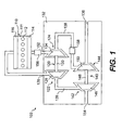
- an exemplary air supply system 100 for an internal combustion engine 110 for example, a four-stroke, diesel engine.
- the internal combustion engine 110 includes an engine block 111 defining a plurality of combustion cylinders 112, the number of which depends upon the particular application. For example, a 4-cylinder engine would include four combustion cylinders, a 6-cylinder engine would include six combustion cylinders, etc. In the exemplary embodiment of FIG. 1 , six combustion cylinders 112 are shown. It should be appreciated that the engine 110 may be any other type of internal combustion engine, for example, a gasoline or natural gas engine.
- the internal combustion engine 110 also includes an intake manifold 114 and an exhaust manifold 116.
- the intake manifold 114 provides fluid, for example, air or a fuel/air mixture, to the combustion cylinders 112.
- the exhaust manifold 116 receives exhaust fluid, for example, exhaust gas, from the combustion cylinders 112.
- the intake manifold 114 and the exhaust manifold 116 are shown as a single-part construction for simplicity in the drawing. However, it should be appreciated that the intake manifold 114 and/or the exhaust manifold 116 may be constructed as multi-part manifolds, depending upon the particular application.
- the air supply system 100 includes a first turbocharger 120 and may include a second turbocharger 140.
- the first and second turbochargers 120, 140 may be arranged in series with one another such that the second turbocharger 140 provides a first stage of pressurization and the first turbocharger 120 provides a second stage of pressurization.
- the second turbocharger 140 may be a low pressure turbocharger and the first turbocharger 120 may be a high pressure turbocharger.
- the first turbocharger 120 includes a turbine 122 and a compressor 124.
- the turbine 122 is fluidly connected to the exhaust manifold 116 via an exhaust duct 126.
- the turbine 122 includes a turbine wheel 128 carried by a shaft 130, which in turn may be rotatably carried by a housing 132, for example, a single-part or multi-part housing.
- the fluid flow path from the exhaust manifold 116 to the turbine 122 may include a variable nozzle (not shown) or other variable geometry arrangement adapted to control the velocity of exhaust fluid impinging on the turbine wheel 128.
- the compressor 124 includes a compressor wheel 134 carried by the shaft 130.
- rotation of the shaft 130 by the turbine wheel 128 in turn may cause rotation of the compressor wheel 134.
- the first turbocharger 120 may include a compressed air duct 138 for receiving compressed air from the second turbocharger 140 and an air outlet line 152 for receiving compressed air from the compressor 124 and supplying the compressed air to the intake manifold 114 of the engine 110.
- the first turbocharger 120 may also include an exhaust duct 139 for receiving exhaust fluid from the turbine 122 and supplying the exhaust fluid to the second turbocharger 140.
- the second turbocharger 140 may include a turbine 142 and a compressor 144.
- the turbine 142 may be fluidly connected to the exhaust duct 139.
- the turbine 142 may include a turbine wheel 146 carried by a shaft 148, which in turn may be rotatably carried by the housing 132.
- the compressor 144 may include a compressor wheel 150 carried by the shaft 148. Thus, rotation of the shaft 148 by the turbine wheel 146 may in turn cause rotation of the compressor wheel 150.
- the second turbocharger 140 may include an air intake line 136 providing fluid communication between the atmosphere and the compressor 144.
- the second turbocharger 140 may also supply compressed air to the first turbocharger 120 via the compressed air duct 138.
- the second turbocharger 140 may include an exhaust outlet 154 for receiving exhaust fluid from the turbine 142 and providing fluid communication with the atmosphere.
- the first turbocharger 120 and second turbocharger 140 may be sized to provide substantially similar compression ratios.
- the first turbocharger 120 and second turbocharger 140 may both provide compression ratios of between 2 to 1 and 3 to 1, resulting in a system compression ratio of at least 4:1 with respect to atmospheric pressure.
- the second turbocharger 140 may provide a compression ratio of 3 to 1 and the first turbocharger 120 may provide a compression ratio of 1.5 to 1, resulting in a system compression ratio of 4.5 to 1 with respect to atmospheric pressure.
- the air supply system 100 may include an air cooler 156, for example, an aftercooler, between the compressor 124 and the intake manifold 114.
- the air cooler 156 may extract heat from the air to lower the intake manifold temperature and increase the air density.
- the air supply system 100 may include an additional air cooler 158, for example, an intercooler, between the compressor 144 of the second turbocharger 140 and the compressor 124 of the first turbocharger 120.
- the air supply system 100 may optionally include an additional air cooler (not shown) between the air cooler 156 and the intake manifold 114. The optional additional air cooler may further reduce the intake manifold temperature.
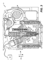
- a cylinder head 211 is connected with the engine block 111.
- Each cylinder 112 in the cylinder head 211 may be provided with a fuel supply system 202.
- the fuel supply system 202 may include a fuel port 204 opening to a combustion chamber 206 within the cylinder 112.
- the fuel supply system 202 may inject fuel, for example, diesel fuel, directly into the combustion chamber 206.
- the cylinder 112 contains a piston 212 slidably movable in the cylinder.
- a crankshaft 213 is rotatably disposed within the engine block 111.
- a connecting rod 215 couples the piston 212 to the crankshaft 213 so that sliding motion of the piston 212 within the cylinder 112 results in rotation of the crankshaft 213.
- rotation of the crankshaft 213 results in a sliding motion of the piston 212.
- an uppermost position of the piston 212 in the cylinder 112 corresponds to a top dead center position of the crankshaft 213, and a lowermost position of the piston 212 in the cylinder 112 corresponds to a bottom dead center position of the crankshaft 213.
- the piston 212 in a conventional, four-stroke engine cycle reciprocates between the uppermost position and the lowermost position during a combustion (or expansion) stroke, an exhaust stroke, and intake stroke, and a compression stroke.
- the crankshaft 213 rotates from the top dead center position to the bottom dead center position during the combustion stroke, from the bottom dead center to the top dead center during the exhaust stroke, from top dead center to bottom dead center during the intake stroke, and from bottom dead center to top dead center during the compression stroke.
- the four-stroke cycle begins again.
- Each piston stroke correlates to about 180° of crankshaft rotation, or crank angle.
- the combustion stroke may begin at about 0° crank angle
- the exhaust stroke at about 180°
- the intake stroke at about 360°
- the compression stroke at about 540°.
- the cylinder 112 includes at least one intake port 208 and at least one exhaust port 210, each opening to the combustion chamber 206.
- the intake port 208 is opened and closed by an intake valve assembly 214
- the exhaust port 210 is opened and closed by an exhaust valve assembly 216.
- the intake valve assembly 214 includes, an intake valve 218 having a head 220 at a first end 222, with the head 220 being sized and arranged to selectively close the intake port 208.
- the second end 224 of the intake valve 218 may be connected to a rocker arm 226 or any other conventional non-hydraulic valve-actuating mechanism.
- the intake valve 218 is be movable between a first position permitting flow from the intake manifold 114 to enter the combustion cylinder 112 and a second position substantially blocking flow from the intake manifold 114 to the combustion cylinder 112.
- a spring 228 may be disposed about the intake valve 218 to bias the intake valve 218 to the second, closed position.
- a camshaft 232 carrying a cam 234 with one or more lobes 236 is arranged to operate the intake valve assembly 214 cyclically based on the configuration of the cam 234, the lobes 236, and the rotation of the camshaft 232 to achieve a desired intake valve timing.
- the exhaust valve assembly 216 may be configured in a manner similar to the intake valve assembly 214 and may be operated by one of the lobes 236 of the cam 234.
- the intake lobe 236 may be configured to operate the intake valve 218 in a conventional Otto or diesel cycle, whereby the intake valve 218 moves to the second position from between about 10° before bottom dead center of the intake stroke and about 10° after bottom dead center of the compression stroke.
- the intake valve assembly 214 includes a variable intake valve closing mechanism 238 structured and arranged to selectively interrupt cyclical movement of and extend the closing timing of the intake valve 218.
- the variable intake valve closing mechanism 238 is operated hydraulically.
- the variable intake valve closing mechanism 238 may be selectively operated to supply hydraulic fluid, for example, at a low pressure or a high pressure, in a manner to resist closing of the intake valve 218 by the bias of the spring 228. That is, after the intake valve 218 is lifted, i.e., opened, by the cam 234, and when the cam 234 is no longer holding the intake valve 218 open, the hydraulic fluid may hold the intake valve 218 open for a desired period. The desired period may change depending on the desired performance of the engine 110.
- the variable intake valve closing mechanism 238 enables the engine 110 to operate under a conventional Otto or diesel cycle or under a variable late-closing Miller cycle.
- the intake valve 218 may begin to open at about 360° crank angle, that is, when the crankshaft 213 is at or near a top dead center position of an intake stroke 406.
- the closing of the intake valve 218 may be selectively varied from about 540° crank angle, that is, when the crank shaft is at or near a bottom dead center position of a compression stroke 407, to about 650° crank angle, that is, about 70° before top center of the combustion stroke 508.
- the intake valve 218 may be held open for a majority portion of the compression stroke 407, that is, for the first half of the compression stroke 407 and a portion of the second half of the compression stroke 407.
- the fuel supply system 202 may include a fuel injector assembly 240, for example, a mechanically-actuated, electronically-controlled unit injector, in fluid communication with a common fuel rail 242.
- the fuel injector assembly 240 may be any common rail type injector and may be actuated and/or operated hydraulically, mechanically, electrically, piezo-electrically, or any combination thereof.
- the common fuel rail 242 provides fuel to the fuel injector assembly 240 associated with each cylinder 112.
- the fuel injector assembly 240 may inject or otherwise spray fuel into the cylinder 112 via the fuel port 204 in accordance with a desired timing.
- a controller 244 may be electrically connected to the variable intake valve closing mechanism 238 and/or the fuel injector assembly 240.
- the controller 244 may be configured to control operation of the variable intake valve closing mechanism 238 and/or the fuel injector assembly 240 based on one or more engine conditions, for example, engine speed, load, pressure, and/or temperature in order to achieve a desired engine performance. It should be appreciated that the functions of the controller 244 may be performed by a single controller or by a plurality of controllers. Similarly, spark timing in a natural gas engine may provide a similar function to fuel injector timing of a compression ignition engine.
- each fuel injector assembly 240 may be associated with an injector rocker arm 250 pivotally coupled to a rocker shaft 252.
- Each fuel injector assembly 240 may include an injector body 254, a solenoid 256, a plunger assembly 258, and an injector tip assembly 260.
- a first end 262 of the injector rocker arm 250 may be operatively coupled to the plunger assembly 258.
- the plunger assembly 258 may be biased by a spring 259 toward the first end 262 of the injector rocker arm 250 in the general direction of arrow 296.
- a second end 264 of the injector rocker arm 250 may be operatively coupled to a camshaft 266.
- the camshaft 266 may include a cam lobe 267 having a first bump 268 and a second bump 270.
- the camshafts 232, 266 and their respective lobes 236, 267 may be combined into a single camshaft (not shown) if desired.
- the bumps 268, 270 may be moved into and out of contact with the second end 264 of the injector rocker arm 250 during rotation of the camshaft 266.
- the bumps 268, 270 may be structured and arranged such that the second bump 270 may provide a pilot injection of fuel at a predetermined crank angle before the first bump 268 provides a main injection of fuel. It should be appreciated that the cam lobe 267 may have only a first bump 268 that injects all of the fuel per cycle.
- the second end 264 of the injector rocker arm 250 is urged in the general direction of arrow 296.
- the rocker arm 250 pivots about the rocker shaft 252 thereby causing the first end 262 to be urged in the general direction of arrow 298.
- the force exerted on the second end 264 by the bumps 268, 270 is greater in magnitude than the bias generated by the spring 259, thereby causing the plunger assembly 258 to be likewise urged in the general direction of arrow 298.
- the bias of the spring 259 urges the plunger assembly 258 in the general direction of arrow 296.
- the first end 262 of the injector rocker arm 250 is likewise urged in the general direction of arrow 296, which causes the injector rocker arm 250 to pivot about the rocker shaft 252 thereby causing the second end 264 to be urged in the general direction of arrow 298.
- the injector body 254 defines a fuel port 272.
- Fuel such as diesel fuel, may be drawn or otherwise aspirated into the fuel port 272 from the fuel rail 242 when the plunger assembly 258 is moved in the general direction of arrow 296.
- the fuel port 272 is in fluid communication with a fuel valve 274 via a first fuel channel 276.
- the fuel valve 274 is, in turn. in fluid communication with a plunger chamber 278 via a second fuel channel 280.
- the solenoid 256 may be electrically coupled to the controller 244 and mechanically coupled to the fuel valve 274. Actuation of the solenoid 256 by a signal from the controller 244 may cause the fuel valve 274 to be switched from an open position to a closed position. When the fuel valve 274 is positioned in its open position, fuel may advance from the fuel port 272 to the plunger chamber 278, and vice versa. However, when the fuel valve 274 is positioned in its closed positioned, the fuel port 272 is isolated from the plunger chamber 278.
- the injector tip assembly 260 may include a check valve assembly 282. Fuel may be advanced from the plunger chamber 278, through an inlet orifice 284, a third fuel channel 286, an outlet orifice 288, and into the cylinder 112 of the engine 110.
- the plunger assembly 258 is urged in the general direction of arrow 296 by the spring 259 thereby causing fuel to be drawn into the fuel port 272 which in turn fills the plunger chamber 278 with fuel.
- the camshaft 266 is further rotated, one of the bumps 268, 270 is moved into contact with the rocker arm 250, thereby causing the plunger assembly 258 to be urged in the general direction of arrow 298.
- the fuel valve 274 remains in its open position, thereby causing the fuel which is in the plunger chamber 278 to be displaced by the plunger assembly 258 through the fuel port 272.
- the fuel valve 274 is positioned in its closed position thereby isolating the plunger chamber 278 from the fuel port 272.
- fluid pressure within the fuel injector assembly 240 increases.
- a predetermined pressure magnitude for example, at about 5500 psi (38 MPa)
- fuel is injected into the cylinder 112.
- Fuel will continue to be injected into the cylinder 112 until the controller 244 signals the solenoid 256 to return the fuel valve 274 to its open position.
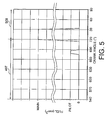
- the pilot injection of fuel may commence when the crankshaft 213 is at about 675° crank angle, that is, about 45° before top dead center of the compression stroke 407.
- the main injection of fuel may occur when the crankshaft 213 is at about 710° crank angle, that is, about 10° before top dead center of the compression stroke 407 and about 45° after commencement of the pilot injection.
- the pilot injection may commence when the crankshaft 213 is about 40-50° before top dead center of the compression stroke 407 and may last for about 10-15° crankshaft rotation.
- the main injection may commence when the crankshaft 213 is between about 10° before top dead center of the compression stroke 407 and about 12° after top dead center of the combustion stroke 508. The main injection may last for about 20-45° crankshaft rotation.
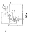
- FIG. 6 is a combination diagrammatic and schematic illustration of a second exemplary air supply system 300 for the internal combustion engine 110.
- the air supply system 300 may include a turbocharger 320, for example, a high-efficiency turbocharger capable of producing at least about a 4 to 1 compression ratio with respect to atmospheric pressure.
- the turbocharger 320 may include a turbine 322 and a compressor 324.
- the turbine 322 may be fluidly connected to the exhaust manifold 116 via an exhaust duct 326.
- the turbine 322 may include a turbine wheel 328 carried by a shaft 330, which in turn may be rotatably carried by a housing 332, for example, a single-part or multi-part housing.
- the fluid flow path from the exhaust manifold 116 to the turbine 322 may include a variable nozzle (not shown), which may control the velocity of exhaust fluid impinging on the turbine wheel 328.
- the compressor 324 may include a compressor wheel 334 carried by the shaft 330. Thus, rotation of the shaft 330 by the turbine wheel 328 in turn may cause rotation of the compressor wheel 334.
- the turbocharger 320 may include an air inlet 336 providing fluid communication between the atmosphere and the compressor 324 and an air outlet 352 for supplying compressed air to the intake manifold 114 of the engine 110.
- the turbocharger 320 may also include an exhaust outlet 354 for receiving exhaust fluid from the turbine 322 and providing fluid communication with the atmosphere.
- the air supply system 300 may include an air cooler 356 between the compressor 324 and the intake manifold 114.
- the air supply system 300 may include an additional air cooler (not shown) between the air cooler 356 and the intake manifold 114.
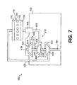
- FIG. 7 is a combination diagrammatic and schematic illustration of a third exemplary air supply system 400 for the internal combustion engine 110.
- the air supply system 400 may include a turbocharger 420, for example, a turbocharger 420 having a turbine 422 and two compressors 424, 444.
- the turbine 422 may be fluidly connected to the exhaust manifold 116 via an inlet duct 426.
- the turbine 422 may include a turbine wheel 428 carried by a shaft 430, which in turn may be rotatably carried by a housing 432, for example, a single-part or multi-part housing.
- the fluid flow path from the exhaust manifold 116 to the turbine 422 may include a variable nozzle (not shown), which may control the velocity of exhaust fluid impinging on the turbine wheel 428.
- the first compressor 424 may include a compressor wheel 434 carried by the shaft 430
- the second compressor 444 may include a compressor wheel 450 carried by the shaft 430.
- rotation of the shaft 430 by the turbine wheel 428 in turn may cause rotation of the first and second compressor wheels 434, 450.
- the first and second compressors 424, 444 may provide first and second stages of pressurization, respectively.
- the turbocharger 420 may include an air intake line 436 providing fluid communication between the atmosphere and the first compressor 424 and a compressed air duct 438 for receiving compressed air from the first compressor 424 and supplying the compressed air to the second compressor 444.
- the turbocharger 420 may include an air outlet line 452 for supplying compressed air from the second compressor 444 to the intake manifold 114 of the engine 110.
- the turbocharger 420 may also include an exhaust outlet 454 for receiving exhaust fluid from the turbine 422 and providing fluid communication with the atmosphere.
- first compressor 424 and second compressor 444 may both provide compression ratios of between 2 to 1 and 3 to 1, resulting in a system compression ratio of at least 4:1 with respect to atmospheric pressure.
- second compressor 444 may provide a compression ratio of 3 to 1 and the first compressor 424 may provide a compression ratio of 1.5 to 1, resulting in a system compression ratio of 4.5 to 1 with respect to atmospheric pressure.
- the air supply system 400 may include an air cooler 456 between the compressor 424 and the intake manifold 114.
- the air supply system 400 may include an additional air cooler 458 between the first compressor 424 and the second compressor 444 of the turbocharger 420.
- the air supply system 400 may optionally include an additional air cooler (not shown) between the air cooler 456 and the intake manifold 114.
- the internal combustion engine 110 operates in a known manner using, for example, the diesel principle of operation.
- exhaust gas from the internal combustion engine 110 is transported from the exhaust manifold 116 through the inlet duct 126 and impinges on and causes rotation of the turbine wheel 128.
- the turbine wheel 128 is coupled with the shaft 130, which in turn carries the compressor wheel 134.
- the rotational speed of the compressor wheel 134 thus corresponds to the rotational speed of the shaft 130.
- the exemplary fuel supply system 200 and cylinder 112 shown in FIG. 2 may be used with each of the exemplary air supply systems 100, 300, 400.
- Compressed air is supplied to the combustion chamber 206 via the intake port 208, and exhaust air exits the combustion chamber 206 via the exhaust port 210.
- the intake valve assembly 214 and the exhaust valve assembly 216 are controllably operated to direct airflow into and out of the combustion chamber 206.
- the intake valve 218 moves from the second position to the first position in a cyclical fashion to allow compressed air to enter the combustion chamber 206 of the cylinder 112 at near top center of the intake stroke 406 (about 360° crank angle), as shown in FIG. 4 .
- the intake valve 218 moves from the first position to the second position to block additional air from entering the combustion chamber 206.
- Fuel may then be injector from the fuel injector assembly 240 at near top dead center of the compression stroke (about 720° crank angle).
- the conventional Otto or diesel cycle is modified by moving the intake valve 218 from the first position to the second position at either some predetermined time before bottom dead center of the intake stroke 406 (i.e., before 540° crank angle) or some predetermined time after bottom dead center of the compression stroke 407 (i.e., after 540° crank angle).
- the intake valve 218 is moved from the first position to the second position during a first portion of the first half of the compression stroke 407.
- variable intake valve closing mechanism 238 enables the engine 110 to be operated in both a late-closing Miller cycle and a conventional Otto or diesel cycle. Further, injecting a substantial portion of fuel after top dead center of the combustion stroke 508, as shown in FIG. 5 , may reduce NO X emissions and increase the amount of energy rejected to the exhaust manifold 116 in the form of exhaust fluid.
- Use of a high-efficiency turbocharger 320, 420 or series turbochargers 120, 140 may enable recapture of at least a portion of the rejected energy from the exhaust.
- the rejected energy may be converted into increased air pressures delivered to the intake manifold 114, which may increase the energy pushing the piston 212 against the crankshaft 213 to produce useable work.
- delaying movement of the intake valve 218 from the first position to the second position may reduce the compression temperature in the combustion chamber 206. The reduced compression temperature may further reduce NO X emissions.
- the controller 244 may operate the variable intake valve closing mechanism 238 to vary the timing of the intake valve assembly 214 to achieve desired engine performance based on one or more engine conditions, for example, engine speed, engine load, engine temperature, boost, and/or manifold intake temperature.
- the variable intake valve closing mechanism 238 may also allow more precise control of the air/fuel ratio.
- the controller 244 may control the cylinder pressure during the compression stroke of the piston 212. For example, late closing of the intake valve reduces the compression work that the piston 212 must perform without compromising cylinder pressure and while maintaining a standard expansion ratio and a suitable air/fuel ratio.
- the high pressure air provided by the exemplary air supply systems 100, 300, 400 may provide extra boost on the induction stroke of the piston 212.
- the high pressure may also enable the intake valve assembly 214 to be closed even later than in a conventional Miller cycle engine.
- the intake valve assembly 214 may remain open until the second half of the compression stroke of the piston 212, for example, as late as about 80° to 70° before top dead center (BTDC). While the intake valve assembly 214 is open, air may flow between the chamber 206 and the intake manifold 114. Thus, the cylinder 112 experiences less of a temperature rise in the chamber 206 during the compression stroke of the piston 212.
- the controller 244 may controllably operate the fuel injector assembly 240 to supply fuel to the combustion chamber 206 after the intake valve assembly 214 is closed.
- the fuel injector assembly 240 may be controlled to supply a pilot injection of fuel contemporaneous with or slightly after the intake valve assembly 214 is closed and to supply a main injection of fuel contemporaneous with or slightly before combustion temperature is reached in the chamber 206.
- a significant amount of exhaust energy may be available for recirculation by the air supply system 100, 300, 400, which may efficiently extract additional work from the exhaust energy.
- the second turbocharger 140 may extract otherwise wasted energy from the exhaust stream of the first turbocharger 120 to turn the compressor wheel 150 of the second turbocharger 140, which is in series with the compressor wheel 134 of the first turbocharger 120.
- the extra restriction in the exhaust path resulting from the addition of the second turbocharger 140 may raise the back pressure on the piston 212.
- the energy recovery accomplished through the second turbocharger 140 may offset the work consumed by the higher back pressure.
- the additional pressure achieved by the series turbochargers 120, 140 may do work on the piston 212 during the induction stroke of the combustion cycle.
- the added pressure on the cylinder resulting from the second turbocharger 140 may be controlled and/or relieved by using the late intake valve closing.
- the series turbochargers 120, 140 may provide fuel efficiency via the air supply system 100, and not simply more power
- the air cooler 156, 356, 456 preceding the intake manifold 114 may extract heat from the air to lower the inlet manifold temperature, while maintaining the denseness of the pressurized air.
- the optional additional air cooler between compressors or after the air cooler 156, 356, 456 may further reduce the inlet manifold temperature, but may lower the work potential of the pressurized air.
- the lower inlet manifold temperature may reduce the NO X emissions.
- An air and fuel supply system for an internal combustion engine in accordance with the exemplary embodiments of the invention may extract additional work from the engine's exhaust.
- the system may also achieve fuel efficiency and reduced NO X emissions, while maintaining work potential and ensuring that the system reliability meets with operator expectations.
Description
- The present invention relates to a combustion engine and, more particularly, to an air and fuel supply system for use with an internal combustion engine.
- An internal combustion engine may include one or more turbochargers for compressing a fluid, which is supplied to one or more combustion chambers within corresponding combustion cylinders. Each turbocharger typically includes a turbine driven by exhaust gases of the engine and a compressor driven by the turbine. The compressor receives the fluid to be compressed and supplies the compressed fluid to the combustion chambers. The fluid compressed by the compressor may be in the form of combustion air or an air/fuel mixture.
- An internal combustion engine may also include a supercharger arranged in series with a turbocharger compressor of an engine.
U.S. Patent No. 6,273,076 (Beck et al., issued 14 August 2001) discloses a supercharger having a turbine that drives a compressor to increase the pressure of air flowing to a turbocharger compressor of an engine. In some situations, the air charge temperature may be reduced below ambient air temperature by an early closing of the intake valve. - Early or late closing of the intake valve, referred to as the "Miller Cycle," may reduce the effective compression ratio of the cylinder, which in turn reduces compression temperature, while maintaining a high expansion ratio.
Consequently, a Miller cycle engine may have improved thermal efficiency and reduced exhaust emissions of, for example, oxides of Nitrogen (NOX). Reduced NOX emissions are desirable. In a conventional Miller cycle engine, the timing of the intake valve close is typically shifted slightly forward or backward from that of the typical Otto cycle engine. For example, in the Miller cycle engine, the intake valve may remain open until the beginning of the compression stroke. - While a turbocharger may utilize some energy from the engine exhaust, the series supercharger/turbocharger arrangement does not utilize energy from the turbocharger exhaust. Furthermore, the supercharger requires an additional energy source.
- The present invention is directed to overcoming one or more of the problems as set forth above.
- According to the invention, a method of operating an internal combustion engine, including at least one cylinder and a piston slidable in the cylinder, is provided. The method includes supplying pressurized air from an intake manifold to an air intake port of a combustion chamber in the cylinder, selectively operating an air intake valve to open the air intake port to allow pressurized air to flow between the combustion chamber and the intake manifold substantially during a majority portion of a compression stroke of the piston, and operably controlling a fuel supply system to inject fuel into the combustion chamber after the intake valve is closed.
- According to another aspect of the invention, an internal combustion engine includes an engine block defining at least one cylinder, a head connected with the engine block, wherein the head includes an air intake port and an exhaust port, and a piston slidable in each cylinder. A combustion chamber is defined by the head, the piston, and the cylinder. The engine includes an air intake valve controllably movable to open and close the air intake port, an air supply system which may include at least one turbocharger fluidly connected to the air intake port, and a fuel supply system operable to controllably inject fuel into the combustion chamber at a selected timing. A variable intake valve closing mechanism is configured to keep the intake valve open by selective actuation of the variable intake valve closing mechanism.
- According to yet another exemplary aspect of the invention, a method of operating an internal combustion engine, including at least one cylinder and a piston slidable in the cylinder, is provided. The method may include imparting rotational movement to a first turbine and a first compressor of a first turbocharger with exhaust air flowing from an exhaust port of the cylinder, and imparting rotational movement to a second turbine and a second compressor of a second turbocharger with exhaust air flowing from an exhaust duct of the first turbocharger. The method may also include compressing air drawn from atmosphere with the second compressor, compressing air received from the second compressor with the first compressor, and supplying pressurized air from the first compressor to an air intake port of a combustion chamber in the cylinder via an intake manifold. The method also includes controllably operating a fuel supply system to inject fuel directly into the combustion chamber, and selectively operating an air intake valve to open the air intake port to allow pressurized air to flow between the combustion chamber and the intake manifold during a portion of a compression stroke of the piston.
- According to still another exemplary aspect of the invention, a method of controlling an internal combustion engine having a variable compression ratio is provided. The engine has a block defining a cylinder, a piston slidable in the cylinder, a head connected with the block, and the piston, the cylinder, and the head defining a combustion chamber. The method includes pressurizing air, supplying the air to an intake manifold, maintaining fluid communication between the combustion chamber and the intake manifold during a portion of an intake stroke and through a predetermined portion of a compression stroke, and supplying a pressurized fuel directly to the combustion chamber during a portion of an combustion stroke.
- It is to be understood that both the foregoing general description and the following detailed description are exemplary and explanatory only and are not restrictive of the invention.
- The accompanying drawings, which are incorporated in and constitute a part of this specification, illustrate several exemplary embodiments of the invention and, together with the description, serve to explain the principles of the invention. In the drawings,
-
FIG. 1 is a combination diagrammatic and schematic illustration of an exemplary air supply system for an internal combustion engine in accordance with the invention; -
FIG. 2 is a combination diagrammatic and schematic illustration of an exemplary engine cylinder in accordance with the invention; -
FIG. 3 is a diagrammatic sectional view of the exemplary engine cylinder ofFIG. 2 ; -
FIG. 4 is a graph illustrating an exemplary intake valve actuation as a function of engine crank angle in accordance with the present invention; -
FIG. 5 is a graph illustrating an exemplary fuel injection as a function of engine crank angle in accordance with the present invention; -
FIG. 6 is a combination diagrammatic and schematic illustration of another exemplary air supply system for an internal combustion engine in accordance with the invention; and -
FIG. 7 is a combination diagrammatic and schematic illustration of yet another exemplary air supply system for an internal combustion engine in accordance with the invention. - Reference will now be made in detail to embodiments of the invention, examples of which are illustrated in the accompanying drawings. Wherever possible, the same reference numbers will be used throughout the drawings to refer to the same or like parts.
- Referring to
FIG. 1 , an exemplaryair supply system 100 for aninternal combustion engine 110, for example, a four-stroke, diesel engine, is provided. Theinternal combustion engine 110 includes anengine block 111 defining a plurality ofcombustion cylinders 112, the number of which depends upon the particular application. For example, a 4-cylinder engine would include four combustion cylinders, a 6-cylinder engine would include six combustion cylinders, etc. In the exemplary embodiment ofFIG. 1 , sixcombustion cylinders 112 are shown. It should be appreciated that theengine 110 may be any other type of internal combustion engine, for example, a gasoline or natural gas engine. - The
internal combustion engine 110 also includes anintake manifold 114 and anexhaust manifold 116. Theintake manifold 114 provides fluid, for example, air or a fuel/air mixture, to thecombustion cylinders 112. Theexhaust manifold 116 receives exhaust fluid, for example, exhaust gas, from thecombustion cylinders 112. Theintake manifold 114 and theexhaust manifold 116 are shown as a single-part construction for simplicity in the drawing. However, it should be appreciated that theintake manifold 114 and/or theexhaust manifold 116 may be constructed as multi-part manifolds, depending upon the particular application. - The
air supply system 100 includes afirst turbocharger 120 and may include asecond turbocharger 140. The first andsecond turbochargers second turbocharger 140 provides a first stage of pressurization and thefirst turbocharger 120 provides a second stage of pressurization. For example, thesecond turbocharger 140 may be a low pressure turbocharger and thefirst turbocharger 120 may be a high pressure turbocharger. Thefirst turbocharger 120 includes aturbine 122 and acompressor 124. Theturbine 122 is fluidly connected to theexhaust manifold 116 via anexhaust duct 126. Theturbine 122 includes aturbine wheel 128 carried by ashaft 130, which in turn may be rotatably carried by ahousing 132, for example, a single-part or multi-part housing. The fluid flow path from theexhaust manifold 116 to theturbine 122 may include a variable nozzle (not shown) or other variable geometry arrangement adapted to control the velocity of exhaust fluid impinging on theturbine wheel 128. - The
compressor 124 includes acompressor wheel 134 carried by theshaft 130. Thus, rotation of theshaft 130 by theturbine wheel 128 in turn may cause rotation of thecompressor wheel 134. - The
first turbocharger 120 may include acompressed air duct 138 for receiving compressed air from thesecond turbocharger 140 and anair outlet line 152 for receiving compressed air from thecompressor 124 and supplying the compressed air to theintake manifold 114 of theengine 110. Thefirst turbocharger 120 may also include anexhaust duct 139 for receiving exhaust fluid from theturbine 122 and supplying the exhaust fluid to thesecond turbocharger 140. - The
second turbocharger 140 may include aturbine 142 and acompressor 144. Theturbine 142 may be fluidly connected to theexhaust duct 139. Theturbine 142 may include aturbine wheel 146 carried by ashaft 148, which in turn may be rotatably carried by thehousing 132. Thecompressor 144 may include acompressor wheel 150 carried by theshaft 148. Thus, rotation of theshaft 148 by theturbine wheel 146 may in turn cause rotation of thecompressor wheel 150. - The
second turbocharger 140 may include anair intake line 136 providing fluid communication between the atmosphere and thecompressor 144. Thesecond turbocharger 140 may also supply compressed air to thefirst turbocharger 120 via thecompressed air duct 138. Thesecond turbocharger 140 may include anexhaust outlet 154 for receiving exhaust fluid from theturbine 142 and providing fluid communication with the atmosphere. In an embodiment, thefirst turbocharger 120 andsecond turbocharger 140 may be sized to provide substantially similar compression ratios. For example, thefirst turbocharger 120 andsecond turbocharger 140 may both provide compression ratios of between 2 to 1 and 3 to 1, resulting in a system compression ratio of at least 4:1 with respect to atmospheric pressure. Alternatively, thesecond turbocharger 140 may provide a compression ratio of 3 to 1 and thefirst turbocharger 120 may provide a compression ratio of 1.5 to 1, resulting in a system compression ratio of 4.5 to 1 with respect to atmospheric pressure. - The
air supply system 100 may include anair cooler 156, for example, an aftercooler, between thecompressor 124 and theintake manifold 114. Theair cooler 156 may extract heat from the air to lower the intake manifold temperature and increase the air density. Optionally, theair supply system 100 may include anadditional air cooler 158, for example, an intercooler, between thecompressor 144 of thesecond turbocharger 140 and thecompressor 124 of thefirst turbocharger 120. Alternatively, theair supply system 100 may optionally include an additional air cooler (not shown) between theair cooler 156 and theintake manifold 114. The optional additional air cooler may further reduce the intake manifold temperature. - Referring now to
FIG. 2 , acylinder head 211 is connected with theengine block 111. Eachcylinder 112 in thecylinder head 211 may be provided with afuel supply system 202. Thefuel supply system 202 may include afuel port 204 opening to acombustion chamber 206 within thecylinder 112. Thefuel supply system 202 may inject fuel, for example, diesel fuel, directly into thecombustion chamber 206. - The
cylinder 112 contains apiston 212 slidably movable in the cylinder. Acrankshaft 213 is rotatably disposed within theengine block 111. A connectingrod 215 couples thepiston 212 to thecrankshaft 213 so that sliding motion of thepiston 212 within thecylinder 112 results in rotation of thecrankshaft 213. Similarly, rotation of thecrankshaft 213 results in a sliding motion of thepiston 212. For example, an uppermost position of thepiston 212 in thecylinder 112 corresponds to a top dead center position of thecrankshaft 213, and a lowermost position of thepiston 212 in thecylinder 112 corresponds to a bottom dead center position of thecrankshaft 213. - As one skilled in the art will recognize, the
piston 212 in a conventional, four-stroke engine cycle reciprocates between the uppermost position and the lowermost position during a combustion (or expansion) stroke, an exhaust stroke, and intake stroke, and a compression stroke. Meanwhile, thecrankshaft 213 rotates from the top dead center position to the bottom dead center position during the combustion stroke, from the bottom dead center to the top dead center during the exhaust stroke, from top dead center to bottom dead center during the intake stroke, and from bottom dead center to top dead center during the compression stroke. Then, the four-stroke cycle begins again. Each piston stroke correlates to about 180° of crankshaft rotation, or crank angle. Thus, the combustion stroke may begin at about 0° crank angle, the exhaust stroke at about 180°, the intake stroke at about 360°, and the compression stroke at about 540°. - The
cylinder 112 includes at least oneintake port 208 and at least oneexhaust port 210, each opening to thecombustion chamber 206. Theintake port 208 is opened and closed by anintake valve assembly 214, and theexhaust port 210 is opened and closed by anexhaust valve assembly 216. Theintake valve assembly 214 includes, anintake valve 218 having ahead 220 at afirst end 222, with thehead 220 being sized and arranged to selectively close theintake port 208. Thesecond end 224 of theintake valve 218 may be connected to arocker arm 226 or any other conventional non-hydraulic valve-actuating mechanism. Theintake valve 218 is be movable between a first position permitting flow from theintake manifold 114 to enter thecombustion cylinder 112 and a second position substantially blocking flow from theintake manifold 114 to thecombustion cylinder 112. Aspring 228 may be disposed about theintake valve 218 to bias theintake valve 218 to the second, closed position. - A
camshaft 232 carrying acam 234 with one ormore lobes 236 is arranged to operate theintake valve assembly 214 cyclically based on the configuration of thecam 234, thelobes 236, and the rotation of thecamshaft 232 to achieve a desired intake valve timing. Theexhaust valve assembly 216 may be configured in a manner similar to theintake valve assembly 214 and may be operated by one of thelobes 236 of thecam 234. In an embodiment, theintake lobe 236 may be configured to operate theintake valve 218 in a conventional Otto or diesel cycle, whereby theintake valve 218 moves to the second position from between about 10° before bottom dead center of the intake stroke and about 10° after bottom dead center of the compression stroke. - The
intake valve assembly 214 includes a variable intakevalve closing mechanism 238 structured and arranged to selectively interrupt cyclical movement of and extend the closing timing of theintake valve 218. The variable intakevalve closing mechanism 238 is operated hydraulically. For example, the variable intakevalve closing mechanism 238 may be selectively operated to supply hydraulic fluid, for example, at a low pressure or a high pressure, in a manner to resist closing of theintake valve 218 by the bias of thespring 228. That is, after theintake valve 218 is lifted, i.e., opened, by thecam 234, and when thecam 234 is no longer holding theintake valve 218 open, the hydraulic fluid may hold theintake valve 218 open for a desired period. The desired period may change depending on the desired performance of theengine 110. Thus, the variable intakevalve closing mechanism 238 enables theengine 110 to operate under a conventional Otto or diesel cycle or under a variable late-closing Miller cycle. - As shown in
FIG. 4 , theintake valve 218 may begin to open at about 360° crank angle, that is, when thecrankshaft 213 is at or near a top dead center position of anintake stroke 406. The closing of theintake valve 218 may be selectively varied from about 540° crank angle, that is, when the crank shaft is at or near a bottom dead center position of acompression stroke 407, to about 650° crank angle, that is, about 70° before top center of thecombustion stroke 508. Thus, theintake valve 218 may be held open for a majority portion of thecompression stroke 407, that is, for the first half of thecompression stroke 407 and a portion of the second half of thecompression stroke 407. - The
fuel supply system 202 may include afuel injector assembly 240, for example, a mechanically-actuated, electronically-controlled unit injector, in fluid communication with acommon fuel rail 242. Alternatively, thefuel injector assembly 240 may be any common rail type injector and may be actuated and/or operated hydraulically, mechanically, electrically, piezo-electrically, or any combination thereof. Thecommon fuel rail 242 provides fuel to thefuel injector assembly 240 associated with eachcylinder 112. Thefuel injector assembly 240 may inject or otherwise spray fuel into thecylinder 112 via thefuel port 204 in accordance with a desired timing. - A
controller 244 may be electrically connected to the variable intakevalve closing mechanism 238 and/or thefuel injector assembly 240. Thecontroller 244 may be configured to control operation of the variable intakevalve closing mechanism 238 and/or thefuel injector assembly 240 based on one or more engine conditions, for example, engine speed, load, pressure, and/or temperature in order to achieve a desired engine performance. It should be appreciated that the functions of thecontroller 244 may be performed by a single controller or by a plurality of controllers. Similarly, spark timing in a natural gas engine may provide a similar function to fuel injector timing of a compression ignition engine. - Referring now to
FIG. 3 , eachfuel injector assembly 240 may be associated with aninjector rocker arm 250 pivotally coupled to arocker shaft 252. Eachfuel injector assembly 240 may include aninjector body 254, asolenoid 256, aplunger assembly 258, and aninjector tip assembly 260. Afirst end 262 of theinjector rocker arm 250 may be operatively coupled to theplunger assembly 258. Theplunger assembly 258 may be biased by aspring 259 toward thefirst end 262 of theinjector rocker arm 250 in the general direction ofarrow 296. - A
second end 264 of theinjector rocker arm 250 may be operatively coupled to acamshaft 266. More specifically, thecamshaft 266 may include a cam lobe 267 having afirst bump 268 and asecond bump 270. Thecamshafts respective lobes 236, 267 may be combined into a single camshaft (not shown) if desired. Thebumps second end 264 of theinjector rocker arm 250 during rotation of thecamshaft 266. Thebumps second bump 270 may provide a pilot injection of fuel at a predetermined crank angle before thefirst bump 268 provides a main injection of fuel. It should be appreciated that the cam lobe 267 may have only afirst bump 268 that injects all of the fuel per cycle. - When one of the
bumps injector rocker arm 250, thesecond end 264 of theinjector rocker arm 250 is urged in the general direction ofarrow 296. As thesecond end 264 is urged in the general direction ofarrow 296, therocker arm 250 pivots about therocker shaft 252 thereby causing thefirst end 262 to be urged in the general direction ofarrow 298. The force exerted on thesecond end 264 by thebumps spring 259, thereby causing theplunger assembly 258 to be likewise urged in the general direction ofarrow 298. When thecamshaft 266 is rotated beyond the maximum height of thebumps spring 259 urges theplunger assembly 258 in the general direction ofarrow 296. As theplunger assembly 258 is urged in the general direction ofarrow 296, thefirst end 262 of theinjector rocker arm 250 is likewise urged in the general direction ofarrow 296, which causes theinjector rocker arm 250 to pivot about therocker shaft 252 thereby causing thesecond end 264 to be urged in the general direction ofarrow 298. - The
injector body 254 defines afuel port 272. Fuel, such as diesel fuel, may be drawn or otherwise aspirated into thefuel port 272 from thefuel rail 242 when theplunger assembly 258 is moved in the general direction ofarrow 296. Thefuel port 272 is in fluid communication with a fuel valve 274 via afirst fuel channel 276. The fuel valve 274 is, in turn. in fluid communication with aplunger chamber 278 via asecond fuel channel 280. - The
solenoid 256 may be electrically coupled to thecontroller 244 and mechanically coupled to the fuel valve 274. Actuation of thesolenoid 256 by a signal from thecontroller 244 may cause the fuel valve 274 to be switched from an open position to a closed position. When the fuel valve 274 is positioned in its open position, fuel may advance from thefuel port 272 to theplunger chamber 278, and vice versa. However, when the fuel valve 274 is positioned in its closed positioned, thefuel port 272 is isolated from theplunger chamber 278. - The
injector tip assembly 260 may include acheck valve assembly 282. Fuel may be advanced from theplunger chamber 278, through aninlet orifice 284, athird fuel channel 286, anoutlet orifice 288, and into thecylinder 112 of theengine 110. - Thus, it should be appreciated that when one of the
bumps injector rocker arm 16, theplunger assembly 258 is urged in the general direction ofarrow 296 by thespring 259 thereby causing fuel to be drawn into thefuel port 272 which in turn fills theplunger chamber 278 with fuel. As thecamshaft 266 is further rotated, one of thebumps rocker arm 250, thereby causing theplunger assembly 258 to be urged in the general direction ofarrow 298. If thecontroller 244 is not generating an injection signal, the fuel valve 274 remains in its open position, thereby causing the fuel which is in theplunger chamber 278 to be displaced by theplunger assembly 258 through thefuel port 272. However, if thecontroller 244 is generating an injection signal, the fuel valve 274 is positioned in its closed position thereby isolating theplunger chamber 278 from thefuel port 272. As theplunger assembly 258 continues to be urged in the general direction ofarrow 298 by thecamshaft 266, fluid pressure within thefuel injector assembly 240 increases. At a predetermined pressure magnitude, for example, at about 5500 psi (38 MPa), fuel is injected into thecylinder 112. Fuel will continue to be injected into thecylinder 112 until thecontroller 244 signals thesolenoid 256 to return the fuel valve 274 to its open position. - As shown in the exemplary graph of
FIG. 5 , the pilot injection of fuel may commence when thecrankshaft 213 is at about 675° crank angle, that is, about 45° before top dead center of thecompression stroke 407. The main injection of fuel may occur when thecrankshaft 213 is at about 710° crank angle, that is, about 10° before top dead center of thecompression stroke 407 and about 45° after commencement of the pilot injection. Generally, the pilot injection may commence when thecrankshaft 213 is about 40-50° before top dead center of thecompression stroke 407 and may last for about 10-15° crankshaft rotation. The main injection may commence when thecrankshaft 213 is between about 10° before top dead center of thecompression stroke 407 and about 12° after top dead center of thecombustion stroke 508. The main injection may last for about 20-45° crankshaft rotation. -
FIG. 6 is a combination diagrammatic and schematic illustration of a second exemplaryair supply system 300 for theinternal combustion engine 110. Theair supply system 300 may include aturbocharger 320, for example, a high-efficiency turbocharger capable of producing at least about a 4 to 1 compression ratio with respect to atmospheric pressure. Theturbocharger 320 may include aturbine 322 and acompressor 324. Theturbine 322 may be fluidly connected to theexhaust manifold 116 via anexhaust duct 326. Theturbine 322 may include aturbine wheel 328 carried by ashaft 330, which in turn may be rotatably carried by ahousing 332, for example, a single-part or multi-part housing. The fluid flow path from theexhaust manifold 116 to theturbine 322 may include a variable nozzle (not shown), which may control the velocity of exhaust fluid impinging on theturbine wheel 328. - The
compressor 324 may include acompressor wheel 334 carried by theshaft 330. Thus, rotation of theshaft 330 by theturbine wheel 328 in turn may cause rotation of thecompressor wheel 334. Theturbocharger 320 may include anair inlet 336 providing fluid communication between the atmosphere and thecompressor 324 and anair outlet 352 for supplying compressed air to theintake manifold 114 of theengine 110. Theturbocharger 320 may also include anexhaust outlet 354 for receiving exhaust fluid from theturbine 322 and providing fluid communication with the atmosphere. - The
air supply system 300 may include anair cooler 356 between thecompressor 324 and theintake manifold 114. Optionally, theair supply system 300 may include an additional air cooler (not shown) between theair cooler 356 and theintake manifold 114. -
FIG. 7 is a combination diagrammatic and schematic illustration of a third exemplaryair supply system 400 for theinternal combustion engine 110. Theair supply system 400 may include aturbocharger 420, for example, aturbocharger 420 having aturbine 422 and twocompressors turbine 422 may be fluidly connected to theexhaust manifold 116 via aninlet duct 426. Theturbine 422 may include aturbine wheel 428 carried by ashaft 430, which in turn may be rotatably carried by ahousing 432, for example, a single-part or multi-part housing. The fluid flow path from theexhaust manifold 116 to theturbine 422 may include a variable nozzle (not shown), which may control the velocity of exhaust fluid impinging on theturbine wheel 428. - The
first compressor 424 may include acompressor wheel 434 carried by theshaft 430, and thesecond compressor 444 may include acompressor wheel 450 carried by theshaft 430. Thus, rotation of theshaft 430 by theturbine wheel 428 in turn may cause rotation of the first andsecond compressor wheels second compressors - The
turbocharger 420 may include anair intake line 436 providing fluid communication between the atmosphere and thefirst compressor 424 and acompressed air duct 438 for receiving compressed air from thefirst compressor 424 and supplying the compressed air to thesecond compressor 444. Theturbocharger 420 may include anair outlet line 452 for supplying compressed air from thesecond compressor 444 to theintake manifold 114 of theengine 110. Theturbocharger 420 may also include anexhaust outlet 454 for receiving exhaust fluid from theturbine 422 and providing fluid communication with the atmosphere. - For example, the
first compressor 424 andsecond compressor 444 may both provide compression ratios of between 2 to 1 and 3 to 1, resulting in a system compression ratio of at least 4:1 with respect to atmospheric pressure. Alternatively, thesecond compressor 444 may provide a compression ratio of 3 to 1 and thefirst compressor 424 may provide a compression ratio of 1.5 to 1, resulting in a system compression ratio of 4.5 to 1 with respect to atmospheric pressure. - The
air supply system 400 may include anair cooler 456 between thecompressor 424 and theintake manifold 114. Optionally, theair supply system 400 may include anadditional air cooler 458 between thefirst compressor 424 and thesecond compressor 444 of theturbocharger 420. Alternatively, theair supply system 400 may optionally include an additional air cooler (not shown) between theair cooler 456 and theintake manifold 114. - During use, the
internal combustion engine 110 operates in a known manner using, for example, the diesel principle of operation. Referring to the exemplary air supply system shown inFIG. 1 , exhaust gas from theinternal combustion engine 110 is transported from theexhaust manifold 116 through theinlet duct 126 and impinges on and causes rotation of theturbine wheel 128. Theturbine wheel 128 is coupled with theshaft 130, which in turn carries thecompressor wheel 134. The rotational speed of thecompressor wheel 134 thus corresponds to the rotational speed of theshaft 130. - The exemplary fuel supply system 200 and
cylinder 112 shown inFIG. 2 may be used with each of the exemplaryair supply systems combustion chamber 206 via theintake port 208, and exhaust air exits thecombustion chamber 206 via theexhaust port 210. Theintake valve assembly 214 and theexhaust valve assembly 216 are controllably operated to direct airflow into and out of thecombustion chamber 206. - In a conventional Otto or diesel cycle mode, the
intake valve 218 moves from the second position to the first position in a cyclical fashion to allow compressed air to enter thecombustion chamber 206 of thecylinder 112 at near top center of the intake stroke 406 (about 360° crank angle), as shown inFIG. 4 . At near bottom dead center of the compression stroke (about 540° crank angle), theintake valve 218 moves from the first position to the second position to block additional air from entering thecombustion chamber 206. Fuel may then be injector from thefuel injector assembly 240 at near top dead center of the compression stroke (about 720° crank angle). - In a conventional Miller cycle engine, the conventional Otto or diesel cycle is modified by moving the
intake valve 218 from the first position to the second position at either some predetermined time before bottom dead center of the intake stroke 406 (i.e., before 540° crank angle) or some predetermined time after bottom dead center of the compression stroke 407 (i.e., after 540° crank angle). In a conventional late-closing Miller cycle, theintake valve 218 is moved from the first position to the second position during a first portion of the first half of thecompression stroke 407. - The variable intake
valve closing mechanism 238 enables theengine 110 to be operated in both a late-closing Miller cycle and a conventional Otto or diesel cycle. Further, injecting a substantial portion of fuel after top dead center of thecombustion stroke 508, as shown inFIG. 5 , may reduce NOX emissions and increase the amount of energy rejected to theexhaust manifold 116 in the form of exhaust fluid. Use of a high-efficiency turbocharger series turbochargers intake manifold 114, which may increase the energy pushing thepiston 212 against thecrankshaft 213 to produce useable work. In addition, delaying movement of theintake valve 218 from the first position to the second position may reduce the compression temperature in thecombustion chamber 206. The reduced compression temperature may further reduce NOX emissions. - The
controller 244 may operate the variable intakevalve closing mechanism 238 to vary the timing of theintake valve assembly 214 to achieve desired engine performance based on one or more engine conditions, for example, engine speed, engine load, engine temperature, boost, and/or manifold intake temperature. The variable intakevalve closing mechanism 238 may also allow more precise control of the air/fuel ratio. By delaying closing of theintake valve assembly 214, thecontroller 244 may control the cylinder pressure during the compression stroke of thepiston 212. For example, late closing of the intake valve reduces the compression work that thepiston 212 must perform without compromising cylinder pressure and while maintaining a standard expansion ratio and a suitable air/fuel ratio. - The high pressure air provided by the exemplary
air supply systems piston 212. The high pressure may also enable theintake valve assembly 214 to be closed even later than in a conventional Miller cycle engine. In the present invention, theintake valve assembly 214 may remain open until the second half of the compression stroke of thepiston 212, for example, as late as about 80° to 70° before top dead center (BTDC). While theintake valve assembly 214 is open, air may flow between thechamber 206 and theintake manifold 114. Thus, thecylinder 112 experiences less of a temperature rise in thechamber 206 during the compression stroke of thepiston 212. - Since the closing of the
intake valve assembly 214 may be delayed, the timing of the fuel supply system may also be retarded. For example, thecontroller 244 may controllably operate thefuel injector assembly 240 to supply fuel to thecombustion chamber 206 after theintake valve assembly 214 is closed. For example, thefuel injector assembly 240 may be controlled to supply a pilot injection of fuel contemporaneous with or slightly after theintake valve assembly 214 is closed and to supply a main injection of fuel contemporaneous with or slightly before combustion temperature is reached in thechamber 206. As a result, a significant amount of exhaust energy may be available for recirculation by theair supply system - Referring to the exemplary
air supply system 100 ofFIG. 1 , thesecond turbocharger 140 may extract otherwise wasted energy from the exhaust stream of thefirst turbocharger 120 to turn thecompressor wheel 150 of thesecond turbocharger 140, which is in series with thecompressor wheel 134 of thefirst turbocharger 120. The extra restriction in the exhaust path resulting from the addition of thesecond turbocharger 140 may raise the back pressure on thepiston 212. However, the energy recovery accomplished through thesecond turbocharger 140 may offset the work consumed by the higher back pressure. For example, the additional pressure achieved by theseries turbochargers piston 212 during the induction stroke of the combustion cycle. Further, the added pressure on the cylinder resulting from thesecond turbocharger 140 may be controlled and/or relieved by using the late intake valve closing. Thus, theseries turbochargers air supply system 100, and not simply more power - It should be appreciated that the
air cooler intake manifold 114 may extract heat from the air to lower the inlet manifold temperature, while maintaining the denseness of the pressurized air. The optional additional air cooler between compressors or after theair cooler - An air and fuel supply system for an internal combustion engine in accordance with the exemplary embodiments of the invention may extract additional work from the engine's exhaust. The system may also achieve fuel efficiency and reduced NOX emissions, while maintaining work potential and ensuring that the system reliability meets with operator expectations.
- It will be apparent to those skilled in the art that various modifications and variations can be made in the disclosed air and fuel supply system for an internal combustion engine without departing from the scope of the invention as defined by the appended claims.
Claims (13)
- A method of operating an internal combustion engine (110) including at least one cylinder (112) and a piston (212) slidable in the cylinder (112), comprising:supplying pressurized air from an intake manifold (114) to an air intake port (208) of a combustion chamber (206) in the cylinder (112);selectively operating an air intake valve (218) to open the air intake port (208) to allow pressurized air to flow between the combustion chamber (206) and the intake manifold (114) substantially during a majority portion of a compression stroke of the piston (212),wherein the selectively operating includes non-hydraulically opening the intake valve (218) by operating a cam (234) and holding the intake valve (218) open by operating a hydraulically operated variable intake valve closing mechanism (238); andoperably controlling a fuel supply system (202) to inject fuel into the combustion chamber (206) after the intake valve (218) is closed.
- An internal combustion engine (110), comprising:an engine block (111) defining at least one cylinder (112);a head (211) connected with said engine block (111), including an air intake port (208), and an exhaust port (210);a piston (212) slidable in each cylinder (112);a combustion chamber (206) being defined by said head (211), said piston (212), and said cylinder (112);an air intake valve (218) controllably movable to open and close the air intake port (208)an air supply system (100) fluidly connected to the air intake port (208) and being configured to supply pressurized air to the air intake port (208);a fuel supply system (202) operable to controllably inject fuel into the combustion chamber (206) at a selected timing;a carn (234) configured to non-hydraulically open the intake valve; anda hydraulically operated variable intake valve closing mechanism (238) configured to keep the intake valve (218) open during a majority portion of a compression stroke of the piston (212) by selective actuation of the variable intake valve closing mechanism (238).
- The engine of claim 2, further including a controller (244) configured to operate the intake valve (218) to remain open for a portion of a second half of the compression stroke.
- The engine of claim 2, wherein the air supply system (100) has a pressure ratio of at least 4:1 with respect to atmospheric pressure.
- The engine of claim 2, wherein said fuel supply system (202) being adapted to provide a pilot injection of fuel and a main injection of fuel.
- The method of claim 1, wherein controlling the fuel supply system (202) includes injecting a pilot injection of fuel and injecting a main injection of fuel.
- The method of claim 6, wherein the main injection of fuel begins during the compression stroke.
- The method of claim 1, further including imparting rotational movement to a turbine (122,142, 322, 422) and a compressor (124, 144, 324, 424, 444) of a turbocharger (120, 140, 320, 420) with exhaust flowing from an exhaust port (210) of the engine (110), and supplying pressurized air from the compressor (124, 144, 324, 424, 444) to the air intake manifold (114).
- The method of claim 8, wherein the turbocharger is a first turbocharger (120), and wherein the method further includes:imparting rotational movement to a second turbine (142) and a second compressor (144) of a second turbocharger (140) with exhaust flowing from an exhaust duct of the first turbocharger (120),compressing air drawn from atmosphere with the second compressor (144), andcompressing air received from the second compressor (144) with the compressor (124) of the first turbocharger (120).
- The engine of claim 2, wherein the engine (110) has a variable compression ratio.
- The engine of claim 2, wherein the air supply system (100) includes at least one turbocharger (120, 140, 320, 420).
- The engine of claim 11, wherein the air supply system (100) includes two turbochargers (120, 140) in series.
- The engine of claim 2, further including a camshaft (266) operatively coupled with the fuel supply system (202) to controllably inject fuel into the combustion chamber (206), wherein said camshaft (266) for said fuel supply system (202) includes a cam lobe (267) having a first bump (268) and a second bump (270).
Applications Claiming Priority (2)
| Application Number | Priority Date | Filing Date | Title |
|---|---|---|---|
| US143908 | 1988-01-13 | ||
| US10/143,908 US6688280B2 (en) | 2002-05-14 | 2002-05-14 | Air and fuel supply system for combustion engine |
Publications (3)
| Publication Number | Publication Date |
|---|---|
| EP1363001A2 EP1363001A2 (en) | 2003-11-19 |
| EP1363001A3 EP1363001A3 (en) | 2005-09-14 |
| EP1363001B1 true EP1363001B1 (en) | 2010-08-11 |
Family
ID=29269715
Family Applications (1)
| Application Number | Title | Priority Date | Filing Date |
|---|---|---|---|
| EP03006344A Expired - Fee Related EP1363001B1 (en) | 2002-05-14 | 2003-03-20 | Air and fuel supply system for combustion engine |
Country Status (4)
| Country | Link |
|---|---|
| US (4) | US6688280B2 (en) |
| EP (1) | EP1363001B1 (en) |
| JP (1) | JP4143468B2 (en) |
| DE (1) | DE60333697D1 (en) |
Families Citing this family (76)
| Publication number | Priority date | Publication date | Assignee | Title |
|---|---|---|---|---|
| US7281527B1 (en) * | 1996-07-17 | 2007-10-16 | Bryant Clyde C | Internal combustion engine and working cycle |
| US7222614B2 (en) * | 1996-07-17 | 2007-05-29 | Bryant Clyde C | Internal combustion engine and working cycle |
| US8215292B2 (en) * | 1996-07-17 | 2012-07-10 | Bryant Clyde C | Internal combustion engine and working cycle |
| US6951211B2 (en) * | 1996-07-17 | 2005-10-04 | Bryant Clyde C | Cold air super-charged internal combustion engine, working cycle and method |
| US7201121B2 (en) * | 2002-02-04 | 2007-04-10 | Caterpillar Inc | Combustion engine including fluidically-driven engine valve actuator |
| US6732685B2 (en) * | 2002-02-04 | 2004-05-11 | Caterpillar Inc | Engine valve actuator |
| US6688280B2 (en) * | 2002-05-14 | 2004-02-10 | Caterpillar Inc | Air and fuel supply system for combustion engine |
| US20050247286A1 (en) * | 2002-02-04 | 2005-11-10 | Weber James R | Combustion engine including fluidically-controlled engine valve actuator |
| US7347171B2 (en) * | 2002-02-04 | 2008-03-25 | Caterpillar Inc. | Engine valve actuator providing Miller cycle benefits |
| US7252054B2 (en) * | 2002-05-14 | 2007-08-07 | Caterpillar Inc | Combustion engine including cam phase-shifting |
| US20050235951A1 (en) * | 2002-05-14 | 2005-10-27 | Weber James R | Air and fuel supply system for combustion engine operating in HCCI mode |
| US7007643B2 (en) * | 2002-12-30 | 2006-03-07 | Caterpillar Inc. | Engine valve actuation system |
| US6807929B2 (en) * | 2002-05-14 | 2004-10-26 | Caterpillar Inc | Engine valve actuation system and method |
| US6928969B2 (en) * | 2002-05-14 | 2005-08-16 | Caterpillar Inc | System and method for controlling engine operation |
| US7069887B2 (en) * | 2002-05-14 | 2006-07-04 | Caterpillar Inc. | Engine valve actuation system |
| US20050241302A1 (en) * | 2002-05-14 | 2005-11-03 | Weber James R | Air and fuel supply system for combustion engine with particulate trap |
| US20050241597A1 (en) * | 2002-05-14 | 2005-11-03 | Weber James R | Air and fuel supply system for a combustion engine |
| US20050247284A1 (en) * | 2002-05-14 | 2005-11-10 | Weber James R | Air and fuel supply system for combustion engine operating at optimum engine speed |
| US20050229900A1 (en) * | 2002-05-14 | 2005-10-20 | Caterpillar Inc. | Combustion engine including exhaust purification with on-board ammonia production |
| US7004122B2 (en) * | 2002-05-14 | 2006-02-28 | Caterpillar Inc | Engine valve actuation system |
| US20050235953A1 (en) * | 2002-05-14 | 2005-10-27 | Weber James R | Combustion engine including engine valve actuation system |
| US20050235950A1 (en) * | 2002-05-14 | 2005-10-27 | Weber James R | Air and fuel supply system for combustion engine |
| US6941909B2 (en) | 2003-06-10 | 2005-09-13 | Caterpillar Inc | System and method for actuating an engine valve |
| US7191743B2 (en) * | 2002-05-14 | 2007-03-20 | Caterpillar Inc | Air and fuel supply system for a combustion engine |
| US20030213444A1 (en) * | 2002-05-14 | 2003-11-20 | Cornell Sean O. | Engine valve actuation system |
| US7100552B2 (en) * | 2002-05-14 | 2006-09-05 | Caterpillar Inc. | Control system and method for variable valve actuation system |
| US20040055549A1 (en) * | 2002-09-25 | 2004-03-25 | Petrie Tad L. | Variable valve timing system for an internal combustion engine |
| US6957634B2 (en) * | 2002-10-04 | 2005-10-25 | Caterpillar Inc. | Engine valve actuator |
| US6959692B2 (en) * | 2003-04-15 | 2005-11-01 | Ford Global Technologies, Llc | Computer controlled engine valve operation |
| SE525219C2 (en) * | 2003-05-15 | 2004-12-28 | Volvo Lastvagnar Ab | Turbocharger system for an internal combustion engine where both compressor stages are of radial type with compressor wheels fitted with reverse swept blades |
| US7178491B2 (en) * | 2003-06-05 | 2007-02-20 | Caterpillar Inc | Control system and method for engine valve actuator |
| US6912458B2 (en) * | 2003-06-25 | 2005-06-28 | Caterpillar Inc | Variable valve actuation control for operation at altitude |
| US6976459B2 (en) * | 2003-07-15 | 2005-12-20 | Caterpillar Inc | Control system and method for a valve actuator |
| DE10335567A1 (en) * | 2003-07-31 | 2005-03-10 | Behr Gmbh & Co Kg | Circuit arrangement for cooling charge air and method for operating such a circuit arrangement |
| US7318398B2 (en) | 2003-08-15 | 2008-01-15 | Caterpillar Inc. | Engine valve actuation system |
| US20050039711A1 (en) * | 2003-08-18 | 2005-02-24 | Bryant Clyde C. | Internal combustion engine and working cycle |
| SE525676C2 (en) * | 2003-08-20 | 2005-04-05 | Scania Cv Ab | Arrangement and procedure for controlling an internal combustion engine |
| SE525677C2 (en) * | 2003-08-20 | 2005-04-05 | Scania Cv Ab | Arrangement and procedure for controlling an internal combustion engine |
| US6935287B2 (en) * | 2003-09-30 | 2005-08-30 | Caterpillar Inc | System and method for actuating an engine valve |
| US20050087159A1 (en) * | 2003-10-28 | 2005-04-28 | Caterpillar, Inc. | Engine valve actuation system |
| US7007650B2 (en) * | 2003-10-31 | 2006-03-07 | Caterpillar Inc | Engine valve actuation system |
| US6988471B2 (en) | 2003-12-23 | 2006-01-24 | Caterpillar Inc | Engine valve actuation system |
| JP2006029247A (en) * | 2004-07-20 | 2006-02-02 | Denso Corp | Stop and start control device for engine |
| US7258100B2 (en) * | 2004-08-03 | 2007-08-21 | Bruce Pinkston | Internal combustion engine control |
| US20060082682A1 (en) * | 2004-10-15 | 2006-04-20 | Hoodman Corporation | Camera LCD screen viewing device |
| US20060112689A1 (en) * | 2004-11-30 | 2006-06-01 | Savage Patrick W Jr | Divided housing turbocharger with a variable nozzle area |
| US20080121218A1 (en) * | 2004-12-13 | 2008-05-29 | Caterpillar Inc. | Electric turbocompound control system |
| DE102005002246A1 (en) | 2005-01-18 | 2006-07-20 | Daimlerchrysler Ag | Internal combustion engine with an exhaust gas recirculation device and method for operating an internal combustion engine |
| DE102005005958A1 (en) | 2005-02-10 | 2006-08-17 | Volkswagen Ag | Internal combustion engine with gas operation |
| DE102005012306A1 (en) * | 2005-03-17 | 2006-09-28 | Daimlerchrysler Ag | Method for operating an internal combustion engine and internal combustion engine for this purpose |
| US20070144175A1 (en) * | 2005-03-31 | 2007-06-28 | Sopko Thomas M Jr | Turbocharger system |
| US8037853B2 (en) * | 2005-04-19 | 2011-10-18 | Len Development Services Usa, Llc | Internal combustion engine with electronic valve actuators and control system therefor |
| US7270093B2 (en) * | 2005-04-19 | 2007-09-18 | Len Development Services Corp. | Internal combustion engine with electronic valve actuators and control system therefor |
| US20060275151A1 (en) * | 2005-06-01 | 2006-12-07 | Caterpillar Inc. | Pump and heat exchanger |
| DE102005029322A1 (en) * | 2005-06-24 | 2006-12-28 | Behr Gmbh & Co. Kg | Exhaust gas recycling and cooling device for engine has first and second exhaust gas heat exchangers combined in structural unit to form module |
| JP4499643B2 (en) * | 2005-09-30 | 2010-07-07 | 日立オートモティブシステムズ株式会社 | Multistage fuel injection internal combustion engine |
| US20070137625A1 (en) * | 2005-12-20 | 2007-06-21 | Daniel Steven A | Controlling size of work machine cooling system |
| US7624592B2 (en) * | 2006-05-17 | 2009-12-01 | Northrop Grumman Corporation | Flexible power and thermal architectures using a common machine |
| EP1936132B1 (en) * | 2006-12-20 | 2008-12-17 | C.R.F. Società Consortile per Azioni | Internal combustion engine with intake valves having a variable actuation and a lift profile including a constant lift boot portion |
| US8794000B2 (en) * | 2007-11-30 | 2014-08-05 | Caterpillar Inc. | Natural gas compression system |
| DE102008046509B4 (en) * | 2008-09-10 | 2022-02-24 | Man Energy Solutions Se | Energy recovery device for a large diesel engine |
| CN102482989B (en) * | 2009-07-02 | 2014-06-11 | 霍尼韦尔国际公司 | Turbocharger system for air-throttled engines |
| US20110214633A1 (en) * | 2010-03-04 | 2011-09-08 | Manousos Pattakos | Duration extender variable valve actuation |
| US20110214632A1 (en) * | 2010-03-08 | 2011-09-08 | Manousos Pattakos | Hydro-mechanical variable valve actuation |
| US8446029B2 (en) | 2010-04-05 | 2013-05-21 | Honeywell International Inc. | Turbomachinery device for both compression and expansion |
| US8544262B2 (en) | 2010-05-03 | 2013-10-01 | Honeywell International, Inc. | Flow-control assembly with a rotating fluid expander |
| FI124121B (en) * | 2010-12-01 | 2014-03-31 | Wärtsilä Finland Oy | Internal combustion engine control method and internal combustion engine |
| EP2705220A1 (en) | 2011-05-05 | 2014-03-12 | Honeywell International Inc. | Flow- control assembly comprising a turbine - generator cartridge |
| CN104220730B (en) | 2012-04-23 | 2017-04-26 | 霍尼韦尔国际公司 | Butterfly bypass valve, and throttle loss recovery system incorporating same |
| DE102013213352B4 (en) * | 2013-03-28 | 2015-04-02 | Mtu Friedrichshafen Gmbh | Method for operating an internal combustion engine, control for an internal combustion engine and internal combustion engine |
| US10113453B2 (en) * | 2015-04-24 | 2018-10-30 | Randy Wayne McReynolds | Multi-fuel compression ignition engine |
| CN106762131B (en) * | 2017-03-14 | 2022-10-14 | 观致汽车有限公司 | Engine system and automobile applying same |
| CN106870131B (en) * | 2017-03-14 | 2023-01-31 | 观致汽车有限公司 | Engine system and automobile applying same |
| DE102017010758A1 (en) * | 2017-11-21 | 2019-05-23 | Daimler Ag | Internal combustion engine for a motor vehicle, and method for operating such an internal combustion engine |
| CN109915252B (en) * | 2019-01-16 | 2023-08-15 | 韩培洲 | Intercooler adiabatic internal combustion engine |
| US10760513B1 (en) * | 2019-04-19 | 2020-09-01 | Caterpillar Inc. | Engine and method for exhaust aftertreatment |
Family Cites Families (231)
| Publication number | Priority date | Publication date | Assignee | Title |
|---|---|---|---|---|
| US1316977A (en) | 1919-09-23 | Cardo | ||
| US883240A (en) * | 1905-11-23 | 1908-03-31 | Louis Gaston Sabathe | Internal-combustion engine. |
| US982251A (en) * | 1908-05-08 | 1911-01-24 | Lewis M Keizer | Internal-combustion engine. |
| US1033939A (en) | 1910-04-30 | 1912-07-30 | Banner Motors Ltd | Internal-combustion engine. |
| US1629327A (en) * | 1921-02-26 | 1927-05-17 | George W Waldo | Internal-combustion engine |
| US1610888A (en) | 1922-04-08 | 1926-12-14 | Sauer William Oswald Hugo | Internal-combustion engine |
| US1562692A (en) | 1922-10-12 | 1925-11-24 | Rochefort-Lucay Claude De | Surcharger for aeroplane engines |
| US1781147A (en) | 1925-10-23 | 1930-11-11 | Standard Oil Dev Co | Supercharger for internal-combustion engines |
| US1825817A (en) | 1926-11-15 | 1931-10-06 | Walker Brooks | Stratifying arrangement for internal combustion engines |
| US1963780A (en) | 1930-10-29 | 1934-06-19 | Bois Marcel Du | Internal combustion engine power unit |
| US2126616A (en) | 1936-07-07 | 1938-08-09 | Ricardo D Cayabyab | Internal combustion engine |
| GB534161A (en) | 1939-01-03 | 1941-02-28 | Milo Ab | Improvements in or relating to internal combustion engines of the four-stroke cycle type |
| US2344993A (en) * | 1939-01-03 | 1944-03-28 | Lysholm Alf | Internal combustion engine |
| US2202227A (en) | 1939-04-28 | 1940-05-28 | Leroy E Noland | Internal combustion engine |
| US2453377A (en) | 1944-01-25 | 1948-11-09 | Carburation Pour L Automobile | Throttle control for the primary and secondary charges of engines |
| US2391176A (en) | 1945-02-07 | 1945-12-18 | Mallory Marion | Internal-combustion engine |
| US2484109A (en) | 1945-03-02 | 1949-10-11 | Helmuth A Meinecke | Valve mechanism |
| US2400247A (en) | 1945-03-14 | 1946-05-14 | Worthington Pump & Mach Corp | Internal-combustion engine |
| US2594845A (en) | 1945-06-04 | 1952-04-29 | Baumann Werner | Two-stroke cycle internal-combustion engine |
| US2614547A (en) | 1946-07-22 | 1952-10-21 | Helmuth A Meinecke | Hydraulic valve tappet operable to vary valve-lift and valve-timing |
| US2633698A (en) * | 1948-02-05 | 1953-04-07 | Nettel Frederick | Turbosupercharger means to heat intake of compression-ignition engine for starting |
| US2484009A (en) | 1948-02-25 | 1949-10-11 | Texas Co | Internal-combustion engine and method of operating same |
| US2522456A (en) | 1948-11-13 | 1950-09-12 | Mallory Marion | Internal-combustion engine |
| US2670595A (en) * | 1949-10-19 | 1954-03-02 | Miller Ralph | High-pressure supercharging system |
| US2644436A (en) | 1950-10-21 | 1953-07-07 | American Locomotive Co | Valve actuating mechanism |
| US2780912A (en) | 1951-08-17 | 1957-02-12 | Miller Ralph | Method and apparatus for varying the final compression temperature in a four cycle internal combustion engine |
| US2780053A (en) * | 1951-12-17 | 1957-02-05 | Napier & Son Ltd | Power units, including reciprocating internal combustion engines and turbo compressors utilizing exhaust gases from such engines |
| US2773490A (en) | 1952-09-23 | 1956-12-11 | Miller Ralph | High expansion, spark ignited, gas burning, internal combustion engines |
| US2910826A (en) | 1952-11-11 | 1959-11-03 | British Internal Combust Eng | Turbo-charged internal combustion engines |
| US2768615A (en) | 1953-04-16 | 1956-10-30 | Texaco Development Corp | Fuel injection systems |
| US2991616A (en) | 1953-12-16 | 1961-07-11 | Miller Ralph | Supercharged intercooled two stroke cycle engine with compression control valve |
| US2739440A (en) * | 1954-04-09 | 1956-03-27 | Maybach Motorenbau Gmbh | Supercharger plant for internal combustion engines |
| US2832324A (en) * | 1955-05-31 | 1958-04-29 | Texas Co | Inertia supercharging of internal combustion engine operating at high speed and withhigh rate of air swirl |
| US2817322A (en) | 1956-04-30 | 1957-12-24 | Miller Ralph | Supercharged engine |
| US3144749A (en) | 1956-11-26 | 1964-08-18 | Miller Ralph | Two cycle supercharged difsel engine |
| US3015934A (en) * | 1956-11-29 | 1962-01-09 | Miller Ralph | Load acceleator for supercharged engine |
| US3029594A (en) | 1960-11-10 | 1962-04-17 | Miller Ralph | Matched turbocharger and engine |
| US3113561A (en) | 1961-01-10 | 1963-12-10 | Ralph M Heintz | Stratified charge two-cycle engine |
| US3186388A (en) | 1962-09-10 | 1965-06-01 | Applic Tech Ind L A T I | Feeding of air for combustion in supercharged internal combustion engines |
| US3180327A (en) * | 1962-11-28 | 1965-04-27 | Gen Motors Corp | Engine |
| GB1062983A (en) * | 1962-12-21 | 1967-03-22 | Perkins Engines Ltd | Pressure charging system for internal combustion engines |
| US3232042A (en) * | 1963-03-25 | 1966-02-01 | Daytona Marine Engine Corp | Engine turbocharging systems |
| FR1397178A (en) | 1963-11-14 | 1965-04-30 | Nordberg Manufacturing Co | Highly supercharged internal combustion engine |
| CH413494A (en) | 1964-01-31 | 1966-05-15 | Sulzer Ag | Supercharged diesel internal combustion engine and method for its operation |
| FR1406600A (en) | 1964-06-09 | 1965-07-23 | Hispano Suiza Sa | Improvements made to turbocooled refrigerated diesel engines |
| US3266234A (en) | 1964-11-13 | 1966-08-16 | Trw Inc | Compression ignition engine and method of operating same |
| US3416502A (en) | 1965-04-22 | 1968-12-17 | Weiss Joseph | Internal combustion engines |
| DE1294088B (en) | 1965-07-31 | 1969-04-30 | Nsu Motorenwerke Ag | Internal combustion engine set |
| US3413965A (en) | 1967-07-13 | 1968-12-03 | Ford Motor Co | Mechanism for varying the operation of a reciprocating member |
| DE1966223A1 (en) | 1968-02-07 | 1971-12-30 | Vehicule Ind Et D Equipements | Internal combustion engine with self-ignition and charging |
| FR2050848A5 (en) * | 1969-06-26 | 1971-04-02 | Saviem | |
| US3591958A (en) | 1970-06-24 | 1971-07-13 | Treadwell Corp | Internal combustion engine cycle |
| FR2138408B1 (en) * | 1971-05-25 | 1973-05-25 | Saviem | |
| JPS517262B2 (en) | 1971-08-23 | 1976-03-06 | ||
| US4149493A (en) | 1972-09-29 | 1979-04-17 | Motoren-Forschungs Gmbh Kg | Multi-cylinder internal combustion engine |
| US4009695A (en) | 1972-11-14 | 1977-03-01 | Ule Louis A | Programmed valve system for internal combustion engine |
| JPS5024630A (en) | 1973-07-09 | 1975-03-15 | ||
| US3986351A (en) | 1973-07-27 | 1976-10-19 | Woods Robert L | Method and apparatus for controlling the air flow in an internal combustion engine |
| JPS5036905U (en) | 1973-08-09 | 1975-04-17 | ||
| US3938483A (en) | 1973-08-20 | 1976-02-17 | Joseph Carl Firey | Gasoline engine torque regulator |
| CH579708A5 (en) | 1973-10-16 | 1976-09-15 | Semt | |
| US4022167A (en) * | 1974-01-14 | 1977-05-10 | Haakon Henrik Kristiansen | Internal combustion engine and operating cycle |
| GB1467969A (en) | 1974-01-14 | 1977-03-23 | Kristiansen H | Internal combustion engine and operating cycle |
| FR2271393A1 (en) * | 1974-02-01 | 1975-12-12 | Alsacienne Constr Meca | |
| US3921403A (en) | 1974-04-30 | 1975-11-25 | Garrett Corp | Auxiliary air supply system and method for turbocharged engines |
| US4033304A (en) | 1974-06-14 | 1977-07-05 | David Luria | Piston-type internal combustion engine |
| US4138973A (en) | 1974-06-14 | 1979-02-13 | David Luria | Piston-type internal combustion engine |
| FR2283314A1 (en) * | 1974-08-01 | 1976-03-26 | France Etat | IMPROVEMENTS FOR SUPERCHARGED INTERNAL COMBUSTION ENGINES, COMPRESSION IGNITION |
| GB1486873A (en) * | 1974-08-06 | 1977-09-28 | Koenig & Bauer Ag | Printing press cylinder with means of securing a mounting block for a printing plate or blanket clamping device |
| US3963006A (en) | 1974-09-03 | 1976-06-15 | Joseph Carl Firey | Oil flow positive valve drive mechanism for gasoline engines |
| JPS5217166B2 (en) * | 1974-09-26 | 1977-05-13 | ||
| JPS5179840A (en) | 1975-01-07 | 1976-07-12 | Honda Motor Co Ltd | |
| US4058096A (en) | 1975-02-18 | 1977-11-15 | Stephen Edward Brown | Apparatus and method for increasing the horsepower of an internal combustion engine |
| US4020809A (en) * | 1975-06-02 | 1977-05-03 | Caterpillar Tractor Co. | Exhaust gas recirculation system for a diesel engine |
| IL47787A (en) | 1975-07-24 | 1979-11-30 | Luria D | Piston-type internal combustion engine |
| US4050435A (en) | 1975-12-02 | 1977-09-27 | Harold L. Fuller, Jr. | Valve control for cylinder cutout system |
| US3995606A (en) | 1976-02-02 | 1976-12-07 | Joseph Carl Firey | Gasoline engine torque regulator with speed correction |
| US4009694A (en) | 1976-04-15 | 1977-03-01 | Joseph Carl Firey | Gasoline engine torque regulator with partial speed correction |
| US4075986A (en) * | 1976-07-12 | 1978-02-28 | Mark Keck | Rotary-poppet valve internal combustion engine |
| FR2372962A1 (en) * | 1976-12-01 | 1978-06-30 | Semt | BOOSTERING UNIT FOR INTERNAL COMBUSTION ENGINES |
| CH622062A5 (en) | 1977-03-07 | 1981-03-13 | Semt | |
| US4132213A (en) | 1977-03-29 | 1979-01-02 | Weaver R Homer | Rotary engine |
| DE2715302C3 (en) | 1977-04-05 | 1980-06-04 | Gert G. Ing.(Grad.) 6200 Wiesbaden Niggemeyer | Rotary piston internal combustion engine |
| US4134371A (en) | 1977-04-28 | 1979-01-16 | Hausknecht Louis A | Valve control system |
| JPS5452218A (en) | 1977-09-30 | 1979-04-24 | Toyota Central Res & Dev Lab Inc | Internal-combustion engine |
| US4423709A (en) * | 1977-12-02 | 1984-01-03 | Arrieta Francisco A | Method and apparatus for economizing fuel consumption in operating a multicylinder internal combustion engine |
| JPS6022170B2 (en) * | 1977-12-02 | 1985-05-31 | トヨタ自動車株式会社 | Combustion accelerator for multi-cylinder internal combustion engines |
| US4161166A (en) | 1977-12-09 | 1979-07-17 | Roznovsky Frank B | Device for selectively controlling the number of operative cylinders in multi-cylinder internal combustion engines |
| US4174683A (en) | 1978-01-20 | 1979-11-20 | Vivian Howard C | High efficiency variable expansion ratio engine |
| JPS54112503A (en) | 1978-02-02 | 1979-09-03 | Komatsu Mfg Co Ltd | Blade automatic controller of bulldozer |
| JPS54141922A (en) | 1978-04-25 | 1979-11-05 | Toyota Motor Corp | Exhaust-gas-recycled internal conbustion engine |
| US4206728A (en) | 1978-05-01 | 1980-06-10 | General Motors Corporation | Hydraulic valve actuator system |
| JPS5914609B2 (en) | 1978-06-22 | 1984-04-05 | 日産自動車株式会社 | Whirlpool chamber diesel engine |
| US4235077A (en) | 1978-10-30 | 1980-11-25 | Bryant Clyde C | Combination engine |
| US4315488A (en) | 1978-11-13 | 1982-02-16 | Toyo Kogyo Co., Ltd. | Rotary piston engine having supercharging means |
| US4215659A (en) | 1978-11-16 | 1980-08-05 | Purification Sciences Inc. | Internal combustion engine |
| US4230075A (en) * | 1978-12-26 | 1980-10-28 | Purification Sciences Inc. | Internal combustion engine |
| US4231225A (en) | 1979-02-05 | 1980-11-04 | Aya Kazim K | Turbocharged engine with pressurized gas recirculation |
| FR2448032A1 (en) | 1979-02-05 | 1980-08-29 | Semt | PROCESS FOR IMPROVING THE EFFICIENCY OF AN INTERNAL COMBUSTION ENGINE, ESPECIALLY SUPERCHARGED |
| DE2911727C2 (en) | 1979-03-24 | 1985-05-30 | Mtu Motoren- Und Turbinen-Union Friedrichshafen Gmbh, 7990 Friedrichshafen | Piston internal combustion engine with at least two exhaust gas turbochargers |
| USRE30565E (en) * | 1979-03-26 | 1981-04-07 | Kristiansen Cycle Engines Ltd. | Internal combustion engine and operating cycle |
| US4261307A (en) * | 1979-09-06 | 1981-04-14 | Sidney Oldberg | Variable valve timing control for internal combustion engines |
| US4327676A (en) * | 1980-03-03 | 1982-05-04 | Mcintire Ray G | Method and apparatus for a low emission diesel engine |
| US4280451A (en) | 1980-04-23 | 1981-07-28 | Moore Edward J | High compression vacuum cycle engine |
| SE422346B (en) * | 1980-07-02 | 1982-03-01 | Hedelin Lars G B | SET TO CONTROL THE PROCEDURE IN A COMBUSTION ENGINE AND COMBUSTION ENGINE FOR REALIZING THE SET |
| DE3138243C2 (en) * | 1980-09-26 | 1983-11-24 | Kanesaka Technical Institute Ltd., Kawasaki, Kanagawa | Supercharged internal combustion engine |
| FR2512496A1 (en) | 1981-09-10 | 1983-03-11 | Semt | METHOD FOR THE AMENAGEMENT OF THE OPERATING CONDITIONS OF AN INTERNAL COMBUSTION ENGINE AND A MOTOR THUS DONE |
| US4566422A (en) * | 1981-09-22 | 1986-01-28 | Mazda Motor Corporation | Fuel intake system for a supercharged engine |
| US4438737A (en) * | 1981-10-13 | 1984-03-27 | Investment Rarities, Incorporated | Apparatus and method for controlling the valve operation of an internal combustion engine |
| US4563132A (en) * | 1981-11-13 | 1986-01-07 | Grimmer John E | Compound turbocharger system for an internal combustion engine |
| US4426848A (en) * | 1981-11-20 | 1984-01-24 | Dresser Industries, Inc. | Turbocharged engine exhaust gas recirculation system |
| US4565167A (en) * | 1981-12-08 | 1986-01-21 | Bryant Clyde C | Internal combustion engine |
| US4446821A (en) * | 1982-01-20 | 1984-05-08 | General Motors Corporation | Internal combustion engine method for delayed reaction stratified combustion |
| US4494506A (en) * | 1982-02-03 | 1985-01-22 | Mazda Motor Corporation | Intake system for an internal combustion engine |
| US4584974A (en) * | 1982-07-27 | 1986-04-29 | Nissan Motor Co., Ltd. | Valve operation changing system of internal combustion engine |
| JPS5946310A (en) * | 1982-09-10 | 1984-03-15 | Mazda Motor Corp | Valve timing control device of engine |
| US4643049A (en) * | 1983-09-20 | 1987-02-17 | Honda Giken Kogyo Kabushiki Kaisha | Control system for a hydraulic transmission to prevent vehicle creep |
| DE3411408A1 (en) * | 1984-03-28 | 1985-10-03 | Mtu Motoren- Und Turbinen-Union Friedrichshafen Gmbh, 7990 Friedrichshafen | PISTON INTERNAL COMBUSTION ENGINE |
| JPH0627488B2 (en) * | 1984-05-14 | 1994-04-13 | 日産自動車株式会社 | Valve timing control device for internal combustion engine |
| JPH0637870B2 (en) * | 1984-05-30 | 1994-05-18 | マツダ株式会社 | Ignition device for supercharged engine |
| US4572114A (en) * | 1984-06-01 | 1986-02-25 | The Jacobs Manufacturing Company | Process and apparatus for compression release engine retarding producing two compression release events per cylinder per engine cycle |
| DE3437330A1 (en) * | 1984-10-11 | 1986-04-24 | M.A.N. Maschinenfabrik Augsburg-Nürnberg AG, 8500 Nürnberg | AIR-COMPRESSING, SELF-IGNITION OR FORD-IGNITIONED 4-STROKE COMBUSTION ENGINE WITH DIRECT FUEL INJECTION, TURBOCHARGING AND LOAD-RELATED INTERNAL EXHAUST GAS RECIRCULATION |
| US4805571A (en) * | 1985-05-15 | 1989-02-21 | Humphrey Cycle Engine Partners, L.P. | Internal combustion engine |
| SE451337B (en) | 1985-07-18 | 1987-09-28 | Volvo Ab | PROCEDURE FOR CONTROL OF WORK PROCEDURE IN A UNDERTAKING COMBUSTION Piston Engine |
| US4730457A (en) * | 1985-10-29 | 1988-03-15 | Fuji Jukogyo Kabushiki Kaisha | Supercharging system for automotive engines |
| US4716863A (en) * | 1985-11-15 | 1988-01-05 | Pruzan Daniel A | Internal combustion engine valve actuation system |
| JPS62228625A (en) * | 1986-03-29 | 1987-10-07 | Toyota Motor Corp | Supercharging controller for diesel engine |
| US4798184A (en) * | 1986-11-17 | 1989-01-17 | Sandor Palko | Extended expansion diesel cycle engine |
| JPH0192525A (en) * | 1987-09-30 | 1989-04-11 | Aisin Seiki Co Ltd | Composite supercharger for engine |
| US4982567A (en) * | 1988-01-29 | 1991-01-08 | Mazda Motor Corporation | Air supply control systems for turbocharged internal combustion engines |
| US4833971A (en) * | 1988-03-09 | 1989-05-30 | Kubik Philip A | Self-regulated hydraulic control system |
| JPH0656106B2 (en) * | 1988-10-29 | 1994-07-27 | マツダ株式会社 | Intake device for supercharged engine |
| GB8904211D0 (en) * | 1989-02-24 | 1989-04-12 | Johnson David M | Curve computer |
| US5002022A (en) * | 1989-08-30 | 1991-03-26 | Cummins Engine Company, Inc. | Valve control system with a variable timing hydraulic link |
| US5000145A (en) * | 1989-12-05 | 1991-03-19 | Quenneville Raymond N | Compression release retarding system |
| JPH03229947A (en) * | 1990-02-05 | 1991-10-11 | Mazda Motor Corp | Engine control device |
| SE467634B (en) * | 1990-05-15 | 1992-08-17 | Volvo Ab | TOUR REGULATION DEVICE |
| US5012778A (en) * | 1990-09-21 | 1991-05-07 | Jacobs Brake Technology Corporation | Externally driven compression release retarder |
| DE69133098T2 (en) * | 1990-11-06 | 2003-04-17 | Mazda Motor | Exhaust gas recirculation system for an internal combustion engine |
| US5392740A (en) * | 1990-11-20 | 1995-02-28 | Mazda Motor Corporation | Gas fuel engine |
| JP2583895Y2 (en) * | 1991-02-19 | 1998-10-27 | 三菱自動車工業株式会社 | diesel engine |
| JP3025332B2 (en) * | 1991-03-28 | 2000-03-27 | マツダ株式会社 | Engine exhaust gas recirculation system |
| EP0540758B1 (en) * | 1991-05-23 | 2000-08-30 | Kabushiki Kaisha Toyoda Jidoshokki Seisakusho | Apparatus for controlling the rotational speed of an engine for a vehicle |
| JP2944264B2 (en) * | 1991-07-23 | 1999-08-30 | 株式会社ユニシアジェックス | Valve train for internal combustion engine |
| JP3357385B2 (en) * | 1991-08-27 | 2002-12-16 | マツダ株式会社 | Engine with turbocharger |
| US5191867A (en) * | 1991-10-11 | 1993-03-09 | Caterpillar Inc. | Hydraulically-actuated electronically-controlled unit injector fuel system having variable control of actuating fluid pressure |
| IT1250793B (en) * | 1991-11-06 | 1995-04-21 | Icom Srl | IMPROVEMENTS IN THE G.P.L. TANKS WITH PARTICULAR REFERENCE TO THE POSITIONING OF THE VALVE GROUPS. |
| US5293741A (en) * | 1992-01-31 | 1994-03-15 | Mazda Motor Corporation | Warming-up system for warming up an engine for an automotive vehicle |
| US5390492A (en) * | 1992-02-21 | 1995-02-21 | Northeastern University | Flow-through particulate incineration system coupled to an aerodynamically regenerated particulate trap for diesel engine exhaust gas |
| DE4308354A1 (en) * | 1992-03-16 | 1993-09-23 | Mazda Motor | Air induction system for vehicle supercharged combustion engine - has by=pass line around intercooler opened and closed at precise pressures between precisely defined upper and lower limits |
| JPH05288123A (en) * | 1992-04-10 | 1993-11-02 | Toyota Motor Corp | Exhaust gas circulation apparatus for internal combustion engine |
| JPH05296070A (en) * | 1992-04-14 | 1993-11-09 | Mazda Motor Corp | Control device for engine with supercharger |
| US5398502A (en) * | 1992-05-27 | 1995-03-21 | Fuji Jukogyo Kabushiki Kaisha | System for controlling a valve mechanism for an internal combustion engine |
| GB9222353D0 (en) * | 1992-10-23 | 1992-12-09 | Ricardo Consulting Eng | Spark ignited internal combustion engines |
| GB2275096B (en) * | 1993-02-15 | 1996-05-22 | Unisia Jecs Corp | Valve control device for internal combustion device |
| DK170121B1 (en) * | 1993-06-04 | 1995-05-29 | Man B & W Diesel Gmbh | Sliding valve and large two stroke internal combustion engine |
| US5417186A (en) * | 1993-06-28 | 1995-05-23 | Clemson University | Dual-acting apparatus for variable valve timing and the like |
| JPH0777073A (en) * | 1993-09-09 | 1995-03-20 | Toyota Motor Corp | Valve timing control device for internal combustion engine |
| US5377631A (en) * | 1993-09-20 | 1995-01-03 | Ford Motor Company | Skip-cycle strategies for four cycle engine |
| WO1995008701A1 (en) * | 1993-09-20 | 1995-03-30 | Mitsubishi Jidosha Kogyo Kabushiki Kaisha | Valve driving system for internal combustion engine |
| JP2982581B2 (en) * | 1993-10-14 | 1999-11-22 | 日産自動車株式会社 | Variable valve train for internal combustion engine |
| US5611204A (en) * | 1993-11-12 | 1997-03-18 | Cummins Engine Company, Inc. | EGR and blow-by flow system for highly turbocharged diesel engines |
| US5367990A (en) * | 1993-12-27 | 1994-11-29 | Ford Motor Company | Part load gas exchange strategy for an engine with variable lift camless valvetrain |
| WO1995024549A1 (en) | 1994-03-07 | 1995-09-14 | Komatsu Ltd. | Variable compression ratio engine |
| JP3232925B2 (en) * | 1994-03-10 | 2001-11-26 | トヨタ自動車株式会社 | Intake air amount calculation device for internal combustion engine |
| DE4414429C1 (en) * | 1994-04-26 | 1995-06-01 | Mtu Friedrichshafen Gmbh | Cooling of hot diesel exhaust gas |
| DE19515508C2 (en) * | 1994-04-28 | 1999-01-28 | Hitachi Ltd | Method and control device for drive control of a vehicle with an internal combustion engine and transmission |
| DE4416572C1 (en) * | 1994-05-11 | 1995-04-27 | Daimler Benz Ag | Turbocharged internal combustion engine |
| US5493798A (en) * | 1994-06-15 | 1996-02-27 | Caterpillar Inc. | Teaching automatic excavation control system and method |
| JPH084505A (en) * | 1994-06-17 | 1996-01-09 | Yamaha Motor Co Ltd | Valve system for engine |
| US5622053A (en) * | 1994-09-30 | 1997-04-22 | Cooper Cameron Corporation | Turbocharged natural gas engine control system |
| US5479890A (en) * | 1994-10-07 | 1996-01-02 | Diesel Engine Retarders, Inc. | Compression release engine brakes with electronically controlled, multi-coil hydraulic valves |
| US5718199A (en) * | 1994-10-07 | 1998-02-17 | Diesel Engine Retarders, Inc. | Electronic controls for compression release engine brakes |
| US5713331A (en) * | 1994-12-21 | 1998-02-03 | Mannesmann Rexroth Gmbh | Injection and exhaust-brake system for an internal combustion engine having several cylinders |
| JP3106890B2 (en) * | 1995-01-11 | 2000-11-06 | トヨタ自動車株式会社 | Valve drive for internal combustion engine |
| DE19502717C1 (en) * | 1995-01-28 | 1996-05-30 | Mtu Friedrichshafen Gmbh | Supercharged, multi-cylinder internal combustion engine with exhaust gas feedback |
| SE503996C2 (en) * | 1995-02-24 | 1996-10-14 | Volvo Ab | Supercharged internal combustion engine |
| US5619965A (en) * | 1995-03-24 | 1997-04-15 | Diesel Engine Retarders, Inc. | Camless engines with compression release braking |
| US5617726A (en) * | 1995-03-31 | 1997-04-08 | Cummins Engine Company, Inc. | Cooled exhaust gas recirculation system with load and ambient bypasses |
| US5495830A (en) * | 1995-04-05 | 1996-03-05 | General Motors Corporation | Variable valve timing |
| JP3298358B2 (en) * | 1995-04-25 | 2002-07-02 | 日産自動車株式会社 | Method and apparatus for controlling compression end temperature in diesel engine |
| JP3123398B2 (en) * | 1995-07-26 | 2001-01-09 | トヨタ自動車株式会社 | Continuous variable valve timing control device for internal combustion engine |
| US5615646A (en) * | 1996-04-22 | 1997-04-01 | Caterpillar Inc. | Method and apparatus for holding a cylinder valve closed during combustion |
| US6951211B2 (en) * | 1996-07-17 | 2005-10-04 | Bryant Clyde C | Cold air super-charged internal combustion engine, working cycle and method |
| US7222614B2 (en) * | 1996-07-17 | 2007-05-29 | Bryant Clyde C | Internal combustion engine and working cycle |
| US8215292B2 (en) * | 1996-07-17 | 2012-07-10 | Bryant Clyde C | Internal combustion engine and working cycle |
| US6279550B1 (en) | 1996-07-17 | 2001-08-28 | Clyde C. Bryant | Internal combustion engine |
| US5724939A (en) * | 1996-09-05 | 1998-03-10 | Caterpillar Inc. | Exhaust pulse boosted engine compression braking method |
| JPH10238354A (en) * | 1996-12-27 | 1998-09-08 | Kanesaka Gijutsu Kenkyusho:Kk | Hybrid supercharged engine |
| US5809964A (en) * | 1997-02-03 | 1998-09-22 | Diesel Engine Retarders, Inc. | Method and apparatus to accomplish exhaust air recirculation during engine braking and/or exhaust gas recirculation during positive power operation of an internal combustion engine |
| IT1291490B1 (en) * | 1997-02-04 | 1999-01-11 | C R F Societa Consotile Per Az | DIESEL CYCLE MULTI-CYLINDER ENGINE WITH VARIABLE ACTING VALVES |
| US6041602A (en) * | 1997-06-09 | 2000-03-28 | Southwest Research Institute | Hydraulically-actuated exhaust gas recirculation system and turbocharger for engines |
| JP3587957B2 (en) * | 1997-06-12 | 2004-11-10 | 日立建機株式会社 | Engine control device for construction machinery |
| US6026786A (en) | 1997-07-18 | 2000-02-22 | Caterpillar Inc. | Method and apparatus for controlling a fuel injector assembly of an internal combustion engine |
| US5875743A (en) * | 1997-07-28 | 1999-03-02 | Southwest Research Institute | Apparatus and method for reducing emissions in a dual combustion mode diesel engine |
| US5862790A (en) * | 1997-09-10 | 1999-01-26 | Ford Global Technologies, Inc. | Method of generating turbulence with intra-cycle cooling for spark ignition engines |
| JP3622446B2 (en) * | 1997-09-30 | 2005-02-23 | 日産自動車株式会社 | Diesel engine combustion control system |
| US6189504B1 (en) * | 1997-11-24 | 2001-02-20 | Diesel Engine Retarders, Inc. | System for combination compression release braking and exhaust gas recirculation |
| US6273076B1 (en) | 1997-12-16 | 2001-08-14 | Servojet Products International | Optimized lambda and compression temperature control for compression ignition engines |
| WO1999042718A1 (en) * | 1998-02-23 | 1999-08-26 | Cummins Engine Company, Inc. | Premixed charge compression ignition engine with optimal combustion control |
| JP3500951B2 (en) * | 1998-03-09 | 2004-02-23 | 株式会社日立製作所 | Non-throttle compression-ignition internal combustion engine and control method thereof |
| JP3521790B2 (en) * | 1998-03-25 | 2004-04-19 | 株式会社デンソー | Control device for internal combustion engine |
| US5937807A (en) * | 1998-03-30 | 1999-08-17 | Cummins Engine Company, Inc. | Early exhaust valve opening control system and method |
| US6170441B1 (en) | 1998-06-26 | 2001-01-09 | Quantum Energy Technologies | Engine system employing an unsymmetrical cycle |
| JP4326044B2 (en) * | 1998-08-21 | 2009-09-02 | 日産自動車株式会社 | 4-cycle internal combustion engine |
| JP2000130200A (en) | 1998-10-30 | 2000-05-09 | Mitsubishi Motors Corp | Controller for diesel engine |
| US6035639A (en) * | 1999-01-26 | 2000-03-14 | Ford Global Technologies, Inc. | Method of estimating mass airflow in turbocharged engines having exhaust gas recirculation |
| US6035640A (en) * | 1999-01-26 | 2000-03-14 | Ford Global Technologies, Inc. | Control method for turbocharged diesel engines having exhaust gas recirculation |
| US6178749B1 (en) * | 1999-01-26 | 2001-01-30 | Ford Motor Company | Method of reducing turbo lag in diesel engines having exhaust gas recirculation |
| DE19909933A1 (en) * | 1999-03-06 | 2000-09-07 | Daimler Chrysler Ag | Exhaust gas cleaning system with internal ammonia generation for nitrogen oxide reduction and operating procedure therefor |
| JP2002541382A (en) * | 1999-04-14 | 2002-12-03 | ディーゼル エンジン リターダーズ,インコーポレイテッド | Exhaust and intake rocker arm assembly for correcting valve lift and valve timing during positive power |
| US6267107B1 (en) * | 2000-02-01 | 2001-07-31 | Michael A. V. Ward | Squishinduced turbulence generating colliding flow coupled spark discharge in an IC engine |
| JP3549779B2 (en) * | 1999-09-17 | 2004-08-04 | 日野自動車株式会社 | Internal combustion engine |
| SE515067C2 (en) * | 1999-10-25 | 2001-06-05 | Volvo Personvagnar Ab | Method for reducing substances in exhaust gases from an internal combustion engine |
| IT1319633B1 (en) * | 2000-01-18 | 2003-10-20 | Fiat Ricerche | METHOD OF ASSESSMENT OF THE FUNCTIONALITY OF A COMMON MANIFOLD INJECTION SYSTEM OF AN INTERNAL COMBUSTION ENGINE. |
| US6302076B1 (en) * | 2000-03-13 | 2001-10-16 | Joseph M. Bredy | Internal combustion engine with intake manifold plenum and method of use |
| AU2001261229A1 (en) * | 2000-05-08 | 2001-11-20 | Cummins, Inc. | Premixed charge compression ignition engine with variable speed soc control and method of operation |
| JP2002070598A (en) * | 2000-09-04 | 2002-03-08 | Nissan Motor Co Ltd | Quick closing miller cycle internal combustion engine |
| DE10104160B4 (en) * | 2001-01-30 | 2008-07-10 | Umicore Ag & Co. Kg | Method for operating an exhaust gas purification system for an internal combustion engine |
| JP4517515B2 (en) * | 2001-02-14 | 2010-08-04 | マツダ株式会社 | 4-cycle engine for automobiles |
| JP3997477B2 (en) | 2001-10-05 | 2007-10-24 | 株式会社デンソー | Control device for internal combustion engine |
| US7201121B2 (en) * | 2002-02-04 | 2007-04-10 | Caterpillar Inc | Combustion engine including fluidically-driven engine valve actuator |
| US6688280B2 (en) * | 2002-05-14 | 2004-02-10 | Caterpillar Inc | Air and fuel supply system for combustion engine |
| US6722349B2 (en) * | 2002-02-04 | 2004-04-20 | Caterpillar Inc | Efficient internal combustion engine valve actuator |
| US7178492B2 (en) * | 2002-05-14 | 2007-02-20 | Caterpillar Inc | Air and fuel supply system for combustion engine |
| US7004122B2 (en) * | 2002-05-14 | 2006-02-28 | Caterpillar Inc | Engine valve actuation system |
| US7191743B2 (en) * | 2002-05-14 | 2007-03-20 | Caterpillar Inc | Air and fuel supply system for a combustion engine |
| US6883314B2 (en) * | 2002-08-01 | 2005-04-26 | Caterpillar Inc. | Cooling of engine combustion air |
| US6679207B1 (en) * | 2003-02-24 | 2004-01-20 | Caterpillar Inc | Engine valve actuation system |
| US20050087159A1 (en) * | 2003-10-28 | 2005-04-28 | Caterpillar, Inc. | Engine valve actuation system |
| US7007650B2 (en) * | 2003-10-31 | 2006-03-07 | Caterpillar Inc | Engine valve actuation system |
-
2002
- 2002-05-14 US US10/143,908 patent/US6688280B2/en not_active Expired - Lifetime
-
2003
- 2003-03-20 DE DE60333697T patent/DE60333697D1/en not_active Expired - Lifetime
- 2003-03-20 EP EP03006344A patent/EP1363001B1/en not_active Expired - Fee Related
- 2003-05-02 JP JP2003127456A patent/JP4143468B2/en not_active Expired - Fee Related
- 2003-12-12 US US10/733,570 patent/US20040118118A1/en not_active Abandoned
-
2005
- 2005-04-14 US US11/105,943 patent/US7204213B2/en not_active Expired - Lifetime
-
2006
- 2006-08-16 US US11/504,771 patent/US20070062192A1/en not_active Abandoned
Also Published As
| Publication number | Publication date |
|---|---|
| US7204213B2 (en) | 2007-04-17 |
| EP1363001A3 (en) | 2005-09-14 |
| JP2003328785A (en) | 2003-11-19 |
| JP4143468B2 (en) | 2008-09-03 |
| US20050183692A1 (en) | 2005-08-25 |
| US20030213462A1 (en) | 2003-11-20 |
| EP1363001A2 (en) | 2003-11-19 |
| US6688280B2 (en) | 2004-02-10 |
| US20070062192A1 (en) | 2007-03-22 |
| US20040118118A1 (en) | 2004-06-24 |
| DE60333697D1 (en) | 2010-09-23 |
Similar Documents
| Publication | Publication Date | Title |
|---|---|---|
| EP1363001B1 (en) | Air and fuel supply system for combustion engine | |
| US6651618B1 (en) | Air and fuel supply system for combustion engine | |
| US7201121B2 (en) | Combustion engine including fluidically-driven engine valve actuator | |
| US7178492B2 (en) | Air and fuel supply system for combustion engine | |
| US7252054B2 (en) | Combustion engine including cam phase-shifting | |
| US20070062193A1 (en) | Combustion engine including fluidically-controlled engine valve actuator | |
| US20070079805A1 (en) | Air and fuel supply system for combustion engine operating at optimum engine speed | |
| US7191743B2 (en) | Air and fuel supply system for a combustion engine | |
| US20070062180A1 (en) | Combustion engine including exhaust purification with on-board ammonia production | |
| US20070089416A1 (en) | Combustion engine including engine valve actuation system | |
| US20070089707A1 (en) | Air and fuel supply system for combustion engine | |
| US20070068149A1 (en) | Air and fuel supply system for combustion engine with particulate trap | |
| EP2146076B1 (en) | Four-cycle engine | |
| US20070089706A1 (en) | Air and fuel supply system for combustion engine operating in HCCI mode | |
| US20070223352A1 (en) | Optical disc assemblies for performing assays | |
| JP2006514200A5 (en) | ||
| US20070220884A1 (en) | Divided housing turbocharger for an engine | |
| GB2410060A (en) | A two-stroke compression-ignition internal combustion engine | |
| US20050241597A1 (en) | Air and fuel supply system for a combustion engine | |
| US6116223A (en) | Cam driven exhaust gas recirculation valve assembly | |
| JPS58119922A (en) | Engine equipped with turbo supercharger | |
| JPH0696977B2 (en) | Engine air blower | |
| WO2017178700A1 (en) | Method for using a combustion engine and combustion engine assembly | |
| JPH085309Y2 (en) | Intake valve device with supercharging nozzle |
Legal Events
| Date | Code | Title | Description |
|---|---|---|---|
| PUAI | Public reference made under article 153(3) epc to a published international application that has entered the european phase |
Free format text: ORIGINAL CODE: 0009012 |
|
| AK | Designated contracting states |
Kind code of ref document: A2 Designated state(s): AT BE BG CH CY CZ DE DK EE ES FI FR GB GR HU IE IT LI LU MC NL PT RO SE SI SK TR |
|
| AX | Request for extension of the european patent |
Extension state: AL LT LV MK |
|
| RIC1 | Information provided on ipc code assigned before grant |
Ipc: 7F 02B 3/00 B Ipc: 7F 02B 37/00 B Ipc: 7F 02D 13/02 A |
|
| PUAL | Search report despatched |
Free format text: ORIGINAL CODE: 0009013 |
|
| AK | Designated contracting states |
Kind code of ref document: A3 Designated state(s): AT BE BG CH CY CZ DE DK EE ES FI FR GB GR HU IE IT LI LU MC NL PT RO SE SI SK TR |
|
| AX | Request for extension of the european patent |
Extension state: AL LT LV MK |
|
| 17P | Request for examination filed |
Effective date: 20060309 |
|
| AKX | Designation fees paid |
Designated state(s): DE GB |
|
| GRAP | Despatch of communication of intention to grant a patent |
Free format text: ORIGINAL CODE: EPIDOSNIGR1 |
|
| GRAS | Grant fee paid |
Free format text: ORIGINAL CODE: EPIDOSNIGR3 |
|
| GRAA | (expected) grant |
Free format text: ORIGINAL CODE: 0009210 |
|
| AK | Designated contracting states |
Kind code of ref document: B1 Designated state(s): DE GB |
|
| REG | Reference to a national code |
Ref country code: GB Ref legal event code: FG4D |
|
| REF | Corresponds to: |
Ref document number: 60333697 Country of ref document: DE Date of ref document: 20100923 Kind code of ref document: P |
|
| PLBE | No opposition filed within time limit |
Free format text: ORIGINAL CODE: 0009261 |
|
| STAA | Information on the status of an ep patent application or granted ep patent |
Free format text: STATUS: NO OPPOSITION FILED WITHIN TIME LIMIT |
|
| 26N | No opposition filed |
Effective date: 20110512 |
|
| REG | Reference to a national code |
Ref country code: DE Ref legal event code: R097 Ref document number: 60333697 Country of ref document: DE Effective date: 20110512 |
|
| PGFP | Annual fee paid to national office [announced via postgrant information from national office to epo] |
Ref country code: DE Payment date: 20130328 Year of fee payment: 11 |
|
| REG | Reference to a national code |
Ref country code: DE Ref legal event code: R119 Ref document number: 60333697 Country of ref document: DE |
|
| REG | Reference to a national code |
Ref country code: DE Ref legal event code: R119 Ref document number: 60333697 Country of ref document: DE Effective date: 20141001 |
|
| PG25 | Lapsed in a contracting state [announced via postgrant information from national office to epo] |
Ref country code: DE Free format text: LAPSE BECAUSE OF NON-PAYMENT OF DUE FEES Effective date: 20141001 |
|
| PGFP | Annual fee paid to national office [announced via postgrant information from national office to epo] |
Ref country code: GB Payment date: 20160224 Year of fee payment: 14 |
|
| GBPC | Gb: european patent ceased through non-payment of renewal fee |
Effective date: 20170320 |
|
| PG25 | Lapsed in a contracting state [announced via postgrant information from national office to epo] |
Ref country code: GB Free format text: LAPSE BECAUSE OF NON-PAYMENT OF DUE FEES Effective date: 20170320 |