EP1362957A1 - Vorrichtung zum Verriegeln eines Werkzeugs an einem Hubwerk - Google Patents
Vorrichtung zum Verriegeln eines Werkzeugs an einem Hubwerk Download PDFInfo
- Publication number
- EP1362957A1 EP1362957A1 EP03101279A EP03101279A EP1362957A1 EP 1362957 A1 EP1362957 A1 EP 1362957A1 EP 03101279 A EP03101279 A EP 03101279A EP 03101279 A EP03101279 A EP 03101279A EP 1362957 A1 EP1362957 A1 EP 1362957A1
- Authority
- EP
- European Patent Office
- Prior art keywords
- latch
- motor
- tool
- bolt
- spring
- Prior art date
- Legal status (The legal status is an assumption and is not a legal conclusion. Google has not performed a legal analysis and makes no representation as to the accuracy of the status listed.)
- Granted
Links
- 230000008878 coupling Effects 0.000 claims abstract description 10
- 238000010168 coupling process Methods 0.000 claims abstract description 10
- 238000005859 coupling reaction Methods 0.000 claims abstract description 10
- 230000009471 action Effects 0.000 description 3
- 230000000903 blocking effect Effects 0.000 description 2
- 241000196324 Embryophyta Species 0.000 description 1
- 240000006829 Ficus sundaica Species 0.000 description 1
- 229910000831 Steel Inorganic materials 0.000 description 1
- 230000004913 activation Effects 0.000 description 1
- 230000008901 benefit Effects 0.000 description 1
- 230000006835 compression Effects 0.000 description 1
- 238000007906 compression Methods 0.000 description 1
- 239000000356 contaminant Substances 0.000 description 1
- 230000009849 deactivation Effects 0.000 description 1
- 210000003608 fece Anatomy 0.000 description 1
- 230000007246 mechanism Effects 0.000 description 1
- 239000011435 rock Substances 0.000 description 1
- 239000010959 steel Substances 0.000 description 1
- XLYOFNOQVPJJNP-UHFFFAOYSA-N water Substances O XLYOFNOQVPJJNP-UHFFFAOYSA-N 0.000 description 1
Images

Classifications
-
- E—FIXED CONSTRUCTIONS
- E02—HYDRAULIC ENGINEERING; FOUNDATIONS; SOIL SHIFTING
- E02F—DREDGING; SOIL-SHIFTING
- E02F3/00—Dredgers; Soil-shifting machines
- E02F3/04—Dredgers; Soil-shifting machines mechanically-driven
- E02F3/28—Dredgers; Soil-shifting machines mechanically-driven with digging tools mounted on a dipper- or bucket-arm, i.e. there is either one arm or a pair of arms, e.g. dippers, buckets
- E02F3/36—Component parts
- E02F3/3604—Devices to connect tools to arms, booms or the like
- E02F3/3609—Devices to connect tools to arms, booms or the like of the quick acting type, e.g. controlled from the operator seat
- E02F3/3636—Devices to connect tools to arms, booms or the like of the quick acting type, e.g. controlled from the operator seat using two or four movable transversal pins
-
- E—FIXED CONSTRUCTIONS
- E02—HYDRAULIC ENGINEERING; FOUNDATIONS; SOIL SHIFTING
- E02F—DREDGING; SOIL-SHIFTING
- E02F3/00—Dredgers; Soil-shifting machines
- E02F3/04—Dredgers; Soil-shifting machines mechanically-driven
- E02F3/28—Dredgers; Soil-shifting machines mechanically-driven with digging tools mounted on a dipper- or bucket-arm, i.e. there is either one arm or a pair of arms, e.g. dippers, buckets
- E02F3/36—Component parts
- E02F3/3604—Devices to connect tools to arms, booms or the like
- E02F3/3609—Devices to connect tools to arms, booms or the like of the quick acting type, e.g. controlled from the operator seat
- E02F3/3663—Devices to connect tools to arms, booms or the like of the quick acting type, e.g. controlled from the operator seat hydraulically-operated
-
- E—FIXED CONSTRUCTIONS
- E02—HYDRAULIC ENGINEERING; FOUNDATIONS; SOIL SHIFTING
- E02F—DREDGING; SOIL-SHIFTING
- E02F3/00—Dredgers; Soil-shifting machines
- E02F3/04—Dredgers; Soil-shifting machines mechanically-driven
- E02F3/28—Dredgers; Soil-shifting machines mechanically-driven with digging tools mounted on a dipper- or bucket-arm, i.e. there is either one arm or a pair of arms, e.g. dippers, buckets
- E02F3/36—Component parts
- E02F3/3604—Devices to connect tools to arms, booms or the like
- E02F3/3609—Devices to connect tools to arms, booms or the like of the quick acting type, e.g. controlled from the operator seat
- E02F3/3672—Devices to connect tools to arms, booms or the like of the quick acting type, e.g. controlled from the operator seat where disengagement is effected by a mechanical lever or handle
Definitions
- the invention relates to a device for fixing a Tool on a hoist, in particular on a front loader, wherein the tool and the hoist by a movable latch are fastened to each other, by a power-operated Motor from a locking position to an unlocked position is movable.
- DE 43 27 942 C is a device for setting a Tool described on a hoist that includes a bolt, which by hand between a locking position in which he the tool on the hoist holds, and an unlocked position is movable, in which he releases the tool. It will suggested that the bolt by means of an electric or Hydraulic motor can be brought into the unlocked position. It Other hoists are known in which a bolt for Setting a tool by a power-operated motor is moved.
- the object underlying the invention is seen therein a device for fixing a tool to a hoist to provide both a manual and a manual motorized movement of the bolt allows.
- the bar both manually, for example, by means of a corresponding handle, as well can be moved by motor.
- the latch can be used in case of errors Supply system of the engine to be moved manually.
- the hoist can be used both on farm tractors with facilities for driving the engine as well as to farm tractors without such Facilities are used.
- the engine is conveniently from the workplace of an operator from remotely controllable.
- appropriate lines available be to the engine, for example, electric, pneumatic or to remotely control and / or pressurize hydraulically. It would be possible also a wireless remote control.
- the switched between the engine and the latch coupling device has - as already stated above - the task, a Moving the activated motor to transfer the bolt, at not activated motor but an undisturbed manual movement to allow the bolt.
- a Moving the activated motor to transfer the bolt at not activated motor but an undisturbed manual movement to allow the bolt.
- it makes sense to connect one element firmly to the latch while another Element is firmly coupled to the engine. If the engine is activated, the element coupled to it comes into contact with the element that is coupled to the latch and moves it and the latch in the unlocked position.
- the element coupled to the bolt when the engine is not activated regardless of the coupled to the engine element moves become.
- the coupling device from a disc firmly attached to the latch, which is coaxial is arranged on a portion of the bolt, and one with the Motor rigidly coupled sleeve constructed, which is also coaxial with the portion of the bolt arranged, but on it displaceable is stored.
- the motor can thus the sleeve against the disc Press to release the latch from the locked position into the latch Spend unlocking position.
- a fork can be used.
- the engine connected element within a coupled with the latch Slot eg a slot or a recess in the bolt
- a lock in the unlocked position makes sense to a tool on the hoist - without disturbing action of the bolt - position to be able to.
- This can serve a longitudinal slot, as he himself DE 43 27 942 C is known.
- the longitudinal slot has one Section of small slit width and a section with larger one Slot width.
- the bolt is opposite the longitudinal slot movable.
- a stop of the bolt has a dimension that bigger than the smaller, but smaller than the bigger one Slit width is. If the bolt is transverse to the extension of Longitudinal slot from the locking position in the Unlocked position, the stop comes out of the Longitudinal slot out and can be done manually and / or by the action of a second spring are moved along the longitudinal slot, especially turned.
- the Movement range preferably selected such that, although the Tool from the hoist is solvable, the stop but not from the Long slot out. As a result, he can not by the second spring are locked in the unlocked position. Of the Latch can be on deactivation of the engine by the first spring get back into the locked position without a manual or by activation of the hoist accomplished Solution of the locking of the bolt in the unlocked position would be required.
- the range of motion corresponds of the motor of manual movement, so that the second spring the Latch locked in the unlocked position.
- the bolt can then manually or by moving the hoist back into the Locking position be brought.
- the engine will suitably by a spring, for example, within his housing is arranged, spent in its rest position. This has the advantage that the piston does not last for a long time Exposed to water and contaminants. In addition, the must Spring that moves the latch back into the locked position, do not move the engine. It can therefore be more compact and be designed cheaper.
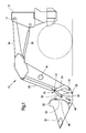
- a hoist 10 shown in Figure 1 the front side a hinted farm tractor is connected, is a Mast 12 shown in a bearing 14 a lifting rocker 16th due to their double-arm design by means of a cross member 18 is stiffened.
- a tool 20, z. Legs Earth shovel, a dung fork, a bale fork or a pallet fork is at the front end of the lifting rocker 16 means a subsequently described adjusting device 30 and a Tool holder 32 movably and interchangeably connected.
- the lifting rocker 16 via Hydraulic motors 26 pivoted about the bearing 14. For adjustment The inclination of the tool 20 engages the adjusting device 30 one end and on the lifting arm 16 another end another Hydraulic motor 28 on.
- the adjusting device 30 acts on the Tool holder 32 to which the tool 20 directly connected is, and consists essentially of a first and a second pivot arm 34, 36 together, the hinged together are connected, wherein in the hinge point 44 of the hydraulic motor 28 attacks.
- the tool holder 32 is in a bearing 38 and the first pivot arm 34 in a bearing 40 on the lifting rock 16 pivoted.
- the second pivot arm 36 is in a warehouse 46 pivotally connected to the tool holder 32.
- At 48 is one Bolt referred to, which will be explained in more detail below.
- a hook 50 and a Bolt 52 is provided, which engages the tool 20 in engagement with the Bring hoist 10.
- the tool holder 32 sits at his Bottom of a extending over the entire width Crossbar 54 and each double arranged walls 56th together, from the end portions of the crossbar 54 penetrated and welded on this.
- the openings 60 serve to receive attached to the latch 48, bolt-shaped Locking parts 64, with the aid of the tool 20 to the Tool holder 32 and therefore connected to the hoist 10 becomes.
- On the tool 20 are at the tool holder 32nd facing side also - but not shown - tabs with such openings attached to each other in alignment can be brought and by the locking parts 64 of the bolt 48th can be pushed.
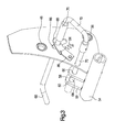
- each side carry in their upper Corner area the bolts 52 for receiving the hooks 50, underneath and to the rear offset the bearing 46 and in the lower right Corner of the bearing 38 for connection to the lifting rocker 16 (s. FIG. 3).
- each two mutually aligned longitudinal slots 66th incorporated, the center line on a circular arc around the Center of the openings 60 is located.
- the longitudinal slot 66 of FIG 2 left wall inside 56 has a about its length about constant slot width.
- the longitudinal slot 66 of FIG. 2 left outside wall 56 has in a lower portion a narrow slot width and in an upper section one wide slot width.
- the bar made of round steel 48 has substantially the shape of a "J" with a first, long leg 68, one second, short leg 70 and a handle 72, of which this connecting web is formed.
- the first long leg 68 is between the handle 72 and a as a right blocking part 64 serving end part in two opposite directions cranked by about 30 ° and with the locking member 64 always in the Opening 60 of the inner flap 58 on the right side.
- the locking member 64 opposite and radial to this offset portion of the long leg 68 extends through both longitudinal slots 66 and carries a sleeve formed Stop 76, which is in the locking position shown in Figure 2 of the bolt 48 each half to the left and right of outer wall 56 extends. The length of yourself in the room between both walls 56 extending portion of the stop 76 substantially corresponds to the travel of the bolt 48 to Lock or unlock the tool 20.
- the outer diameter this stop 76 is smaller than the large slot width, but larger than the small slot width of the outer longitudinal slot 66th
- the long leg 68 is concentric with a Surround spring 78, on the one hand at one of the long leg 68th attached disk 80 and other end to one on the wall 56th slidably adjacent disc 82 bears under prestress, wherein the diameter of the disc 82 is larger than the longitudinal slot 66 wide in its widest section.
- the handle 72 is bent twice in opposite directions by 90 ° and extends outwardly from the outer wall 56 an area easily accessible to an operator.
- the second, short leg 70 extends to the long leg 68 in the area parallel to the bend and extends through the openings 60 of the left side and accordingly aligned, possibly surrounded by guides holes 74 in the left-side walls 56.
- the second short leg 70 points also serving as a blocking part 64 end portion, the always guided in the opening 60 of the left-side tab 58 is.
- the spring 78 is designed as a helical compression spring and so used and curious that they always look at the latch 48 2 pushes to the right, so that its locking parts 64 all Enforce tabs 58.
- a power-operated motor 90 in the form of a Hydraulic cylinder provided, extending in the longitudinal direction of Crossbar 54 extending housing on the crossbar 54th is attached.
- the piston of the motor 90 is provided with a sleeve 92 connected to the long leg 68 of the bolt 48 in Neighborhood of the drawn on the right in Figure 2 tab 58th encloses.
- the sleeve 92 is near one with the long leg 68 fixedly connected disc 94 is arranged.
- the piston of the engine 90 is arranged, the sleeve 92 from that in Figure 2 moved rest position to the left to move. To this Way, there is the possibility of the latch 48 remotely controlled in to spend an unlocked position.
- a second spring 84 cooperates with the latch 48.
- the Spring 84 is one end on the inner left wall 56 and the other end attached to a rocker 86, which at the inner wall 56 about a parallel to the crossbar 54 extending Rotary axis is hinged pivotally.
- the long leg 68 of the Bar 48 penetrates an opening 88 in the rocker 86.
- the latch 48 is in its unlocked position locked and can be released by manual operation.
- the latch 48 also, as before described, manually outward in the unlocked position pulled where it by the second spring 84 to the by the Openings 60 extending axis with a view of Figure 3 in Is pulled clockwise, so that the stop 76 at the Outside of the left outer wall 56 in the area of the small Slot width of the longitudinal slot 66 is moved.
- the spring 78 is biased and the latch 48 is in the held disengaged position. Subsequently, by means of or the bolt 52 and the hook 50 or the tool 20 be picked up and raised so that the tool side Tab between the tabs 58 passes to the crossbar 54 and all openings 60 are aligned. Finally, by means of the Hydraulic motor 28, the tool 20 is tilted to the lifting rocker 16, so that the stop 76 comes to the Hubschwinge 16 to the plant and is pivoted in the area of the large slot width. There arrived, the latch 48 with the two locking parts 64 under the action of the spring 78 with a view to the figure 2 to the right pushed, so that the two locking parts 64 all tabs penetrate and set the tool 20.
- the motor 90 is again activated (or it remains activated), the tabs of the tool 20 are positioned between the tabs 58 and the motor 90th will eventually be disabled.
- the spring 78 then pushes the Locking parts 64 between the tabs 58; the tool 20 is locked.
- Range of movement of the motor 90 that of the manual movement. Of the Latch is in this embodiment in the unlocked position as described above arrested and released again.
- the coupling device constructed from the sleeve 92 and the disc 94 between the motor 90 and the latch 48, the bolt by the motor 90 and independently to manually actuate.
- the spring 78 allows the use of the coupling device and a single-acting hydraulic cylinder as Engine 90.
Landscapes
- Engineering & Computer Science (AREA)
- Mechanical Engineering (AREA)
- Mining & Mineral Resources (AREA)
- Civil Engineering (AREA)
- General Engineering & Computer Science (AREA)
- Structural Engineering (AREA)
- Agricultural Machines (AREA)
- Shovels (AREA)
- Load-Engaging Elements For Cranes (AREA)
- Soil Working Implements (AREA)
- Dental Tools And Instruments Or Auxiliary Dental Instruments (AREA)
- Lifting Devices For Agricultural Implements (AREA)
- Gripping On Spindles (AREA)
- Lock And Its Accessories (AREA)
Abstract
Description
- Fig. 1
- ein Hubwerk mit einem Werkzeug in Seitenansicht,
- Fig. 2
- eine Vorrichtung zum Festlegen des Werkzeugs an dem Hubwerk in Vorderansicht und
- Fig. 3
- eine perspektivische Seitenansicht des linken Teils der Vorrichtung aus Figur 2.
Claims (11)
- Vorrichtung zum Festlegen eines Werkzeugs (20) an einem Hubwerk (10), insbesondere an einem Frontlader, wobei das Werkzeug (20) und das Hubwerk (10) durch einen beweglichen Riegel (48) aneinander befestigbar sind, der durch einen fremdkraftbetätigten Motor (90) von einer Verriegelungsstellung in eine Entriegelungsstellung bewegbar ist, dadurch gekennzeichnet, dass der Motor (90) durch eine Kupplungseinrichtung mit dem Riegel (48) gekoppelt ist, die eingerichtet ist, nur bei aktiviertem Motor (90) eine Antriebsverbindung zwischen dem Motor (90) und dem Riegel (48) herzustellen.
- Vorrichtung nach Anspruch 1, dadurch gekennzeichnet, dass der Riegel (48) einen Griff (72) zum manuellen Bewegen des Riegels (48) zwischen der Verriegelungsstellung und der Entriegelungsstellung aufweist.
- Vorrichtung nach Anspruch 1 oder 2, dadurch gekennzeichnet, dass der Motor (90) vom Arbeitsplatz eines Bedieners aus fernsteuerbar ist.
- Vorrichtung nach einem der Ansprüche 1 bis 3, gekennzeichnet durch eine Feder (78), die den Riegel (48) in die Verriegelungsstellung vorspannt.
- Vorrichtung nach einem der vorhergehenden Ansprüche, dadurch gekennzeichnet, dass die Kupplungseinrichtung ein mit dem Riegel (48) gekoppeltes Element umfasst, an das bei aktiviertem Motor (90) ein mit dem Motor (90) gekoppeltes Element in Anlage gelangt und es bewegt.
- Vorrichtung nach Anspruch 5, dadurch gekennzeichnet, dass das mit dem Riegel (48) gekoppelte Element eine mit dem Riegel (48) verbundene, dazu konzentrische Scheibe (94) ist, und dass das mit dem Motor (90) gekoppelte Element eine zur Scheibe (94) koaxiale Hülse (92) ist, die einen Abschnitt des Riegels (48) umschließt und verschiebbar darauf angeordnet ist.
- Vorrichtung nach einem der vorhergehenden Ansprüche, dadurch gekennzeichnet, dass der Riegel (48) in der Entriegelungsstellung arretierbar ist.
- Vorrichtung nach Anspruch 7, dadurch gekennzeichnet, dass der Riegel (48) entlang eines Längsschlitzes (66) beweglich ist, der einen Abschnitt mit einer größeren Schlitzbreite und einen Abschnitt mit kleinerer Schlitzbreite aufweist, dass der Riegel (48) einen Anschlag (76) mit Abmessungen enthält, die größer als die des Abschnitts des Längsschlitzes (66) mit kleinerer Schlitzbreite und kleiner als die des Abschnitts mit größerer Schlitzbreite sind, und dass der Anschlag (76) bei in die Entriegelungsstellung verbrachtem Riegel (48) in Anlage an den Abschnitt des Längsschlitzes mit kleinerer Schlitzbreite bringbar ist, um den Riegel (48) in der Entriegelungsstellung zu arretieren.
- Vorrichtung nach Anspruch 7 oder 8, dadurch gekennzeichnet, dass der Riegel (48) in der Entriegelungsstellung durch eine zweite Feder (84) in Richtung auf seine Arretierposition zu vorgespannt wird.
- Vorrichtung nach einem der Ansprüche 7 bis 9, dadurch gekennzeichnet, dass der Bewegungsbereich des Motors (90) derart groß ist, dass er den Riegel (48) zwar in eine Position bringen kann, in der das Werkzeug (20) vom Hubwerk (10) trennbar ist, aber nicht so groß ist, dass der Riegel (48) in die Arretierposition gelangt.
- Vorrichtung nach einem der Ansprüche 7 bis 9, dadurch gekennzeichnet, dass der Bewegungsbereich des Motors (90) derart groß ist, dass der Riegel (48) in der Entriegelungsposition selbsttätig arretiert wird, und dass der Motor (90) nach dem Arretieren des Riegels (48) in der Entriegelungsposition entspannt und durch eine Feder in die Ruheposition verbracht wird.
Applications Claiming Priority (2)
| Application Number | Priority Date | Filing Date | Title |
|---|---|---|---|
| DE10221941A DE10221941A1 (de) | 2002-05-17 | 2002-05-17 | Vorrichtung zum Festlegen eines Werkzeugs an einem Hubwerk |
| DE10221941 | 2002-05-17 |
Publications (2)
| Publication Number | Publication Date |
|---|---|
| EP1362957A1 true EP1362957A1 (de) | 2003-11-19 |
| EP1362957B1 EP1362957B1 (de) | 2008-08-06 |
Family
ID=29265332
Family Applications (1)
| Application Number | Title | Priority Date | Filing Date |
|---|---|---|---|
| EP03101279A Expired - Lifetime EP1362957B1 (de) | 2002-05-17 | 2003-05-08 | Vorrichtung zum Verriegeln eines Werkzeugs an einem Hubwerk |
Country Status (6)
| Country | Link |
|---|---|
| US (1) | US7001136B2 (de) |
| EP (1) | EP1362957B1 (de) |
| AT (1) | ATE403781T1 (de) |
| CA (1) | CA2428763C (de) |
| DE (2) | DE10221941A1 (de) |
| ES (1) | ES2307873T3 (de) |
Cited By (3)
| Publication number | Priority date | Publication date | Assignee | Title |
|---|---|---|---|---|
| FR2869054A1 (fr) * | 2004-04-14 | 2005-10-21 | Etude Et D Innovation Dans Le | Dispositif de verrouillage d'un outil sur le cadre porte-outil d'un chargeur, notamment a usage agricole. |
| WO2012085418A1 (fr) * | 2010-12-22 | 2012-06-28 | Mailleux | Cadre porte-outil pour chargeur, notamment pour chargeur equipant un engin agricole, permettant de securiser le verrouillage d'un outil |
| DE102013002622A1 (de) * | 2013-02-18 | 2014-09-04 | Isfort Staplertechnik GmbH & Co. KG | Vorrichtung und Verfahren zum autonomen Kuppeln eines Werkzeugs an ein Arbeitsfahrzeug |
Families Citing this family (8)
| Publication number | Priority date | Publication date | Assignee | Title |
|---|---|---|---|---|
| US7699577B2 (en) * | 2006-06-01 | 2010-04-20 | Clark Equipment Company | Interface plate for mounting a light duty attachment to a lift arm assembly |
| US7824145B2 (en) * | 2007-01-19 | 2010-11-02 | Clark Equipment Company | Common pivot and support member for attachment interface |
| DE102010038469A1 (de) * | 2010-07-27 | 2012-04-05 | Deere & Company | Frontladeranordnung |
| GB201315938D0 (en) * | 2013-09-06 | 2013-10-23 | 1708828 Onatio Ltd | Self-locking attachment coupler for tractor/loader |
| US10106950B2 (en) * | 2013-09-06 | 2018-10-23 | 1708828 Ontario Limited | Self-locking attachment coupler |
| US11242668B2 (en) * | 2019-07-12 | 2022-02-08 | Daedong Mobility Corp. | Quick joint of front loader |
| US12305680B2 (en) * | 2020-12-21 | 2025-05-20 | Kubota Corporation | Locking bracket and methods of using the same |
| US20260078560A1 (en) * | 2024-09-16 | 2026-03-19 | Deere & Company | Carrier frame and latch mechanism |
Citations (5)
| Publication number | Priority date | Publication date | Assignee | Title |
|---|---|---|---|---|
| US5263810A (en) * | 1991-01-16 | 1993-11-23 | Kubota Corporation | Working implement connection structure for a working vehicle having a boom assembly |
| US5466113A (en) * | 1993-08-19 | 1995-11-14 | Deere & Company | Arrangement for the retention of an implement to a lifting gear |
| US5562397A (en) * | 1994-07-13 | 1996-10-08 | Clark Equipment Company | Power actuator for attachment plate |
| US6154989A (en) * | 1997-03-10 | 2000-12-05 | Clark Equipment Company | Attachment construction for earthworking implement |
| EP1138833A1 (de) * | 2000-03-27 | 2001-10-04 | C.M. S.N.C. DI Cangini Giorgio & C. | Vorrichtung zur schnellen montage und demontage eines baggergerätes an einem hydraulischen bagger |
Family Cites Families (1)
| Publication number | Priority date | Publication date | Assignee | Title |
|---|---|---|---|---|
| NO106518L (de) * | 1964-03-14 | 1900-01-01 |
-
2002
- 2002-05-17 DE DE10221941A patent/DE10221941A1/de not_active Ceased
-
2003
- 2003-05-08 AT AT03101279T patent/ATE403781T1/de active
- 2003-05-08 DE DE50310271T patent/DE50310271D1/de not_active Expired - Lifetime
- 2003-05-08 EP EP03101279A patent/EP1362957B1/de not_active Expired - Lifetime
- 2003-05-08 ES ES03101279T patent/ES2307873T3/es not_active Expired - Lifetime
- 2003-05-13 US US10/438,155 patent/US7001136B2/en not_active Expired - Lifetime
- 2003-05-15 CA CA002428763A patent/CA2428763C/en not_active Expired - Lifetime
Patent Citations (5)
| Publication number | Priority date | Publication date | Assignee | Title |
|---|---|---|---|---|
| US5263810A (en) * | 1991-01-16 | 1993-11-23 | Kubota Corporation | Working implement connection structure for a working vehicle having a boom assembly |
| US5466113A (en) * | 1993-08-19 | 1995-11-14 | Deere & Company | Arrangement for the retention of an implement to a lifting gear |
| US5562397A (en) * | 1994-07-13 | 1996-10-08 | Clark Equipment Company | Power actuator for attachment plate |
| US6154989A (en) * | 1997-03-10 | 2000-12-05 | Clark Equipment Company | Attachment construction for earthworking implement |
| EP1138833A1 (de) * | 2000-03-27 | 2001-10-04 | C.M. S.N.C. DI Cangini Giorgio & C. | Vorrichtung zur schnellen montage und demontage eines baggergerätes an einem hydraulischen bagger |
Cited By (5)
| Publication number | Priority date | Publication date | Assignee | Title |
|---|---|---|---|---|
| FR2869054A1 (fr) * | 2004-04-14 | 2005-10-21 | Etude Et D Innovation Dans Le | Dispositif de verrouillage d'un outil sur le cadre porte-outil d'un chargeur, notamment a usage agricole. |
| EP1586708A3 (de) * | 2004-04-14 | 2006-07-05 | Societe D'etudes Et D'innovation Dans Le Materiel Agricole (Seima) | Vorrichtung für die Verriegelung eines Werkzeugs an den Rahmen eines Laders, insbesondere eines landwirtschaftlichen Laders |
| WO2012085418A1 (fr) * | 2010-12-22 | 2012-06-28 | Mailleux | Cadre porte-outil pour chargeur, notamment pour chargeur equipant un engin agricole, permettant de securiser le verrouillage d'un outil |
| FR2969674A1 (fr) * | 2010-12-22 | 2012-06-29 | Mailleux | Cadre porte-outil pour chargeur, notamment pour chargeur equipant un engin agricole, permettant de securiser le verrouillage d'un outil |
| DE102013002622A1 (de) * | 2013-02-18 | 2014-09-04 | Isfort Staplertechnik GmbH & Co. KG | Vorrichtung und Verfahren zum autonomen Kuppeln eines Werkzeugs an ein Arbeitsfahrzeug |
Also Published As
| Publication number | Publication date |
|---|---|
| DE10221941A1 (de) | 2003-12-04 |
| ATE403781T1 (de) | 2008-08-15 |
| EP1362957B1 (de) | 2008-08-06 |
| CA2428763C (en) | 2007-09-11 |
| DE50310271D1 (de) | 2008-09-18 |
| CA2428763A1 (en) | 2003-11-17 |
| ES2307873T3 (es) | 2008-12-01 |
| US20040228716A1 (en) | 2004-11-18 |
| US7001136B2 (en) | 2006-02-21 |
Similar Documents
| Publication | Publication Date | Title |
|---|---|---|
| DE4327942C1 (de) | Vorrichtung zum Festlegen eines Werkzeugs an einem Hubwerk | |
| EP1362956B1 (de) | Vorrichtung zum Verriegeln eines Werkzeugs an einem Hubwerk | |
| DE69533034T2 (de) | Betätigungsorgan für eine kupplungsvorrichtung | |
| EP0542120B1 (de) | Verriegelungseinrichtung für ein Zubehörteil | |
| DE3924313C2 (de) | Schnellwechselvorrichtung für ein Frontladegerät | |
| EP0695655B1 (de) | Zugvorrichtung und Verriegelungsvorrichtung | |
| DE2549416C3 (de) | Anbauvorrichtung zur lösbaren Befestigung von Anbau- oder Zusatzgeräten an einem Fahrzeugaufbau | |
| DE2601565C3 (de) | Sicherheits-Sperrvorrichtung für Stützarme eines Fahrzeuges, insbesondere eines fahrbaren Krans | |
| DE3707215A1 (de) | Verfahren und vorrichtung zum ausfahren eines frei auskragenden endbereichs eines kranauslegers | |
| EP1362957B1 (de) | Vorrichtung zum Verriegeln eines Werkzeugs an einem Hubwerk | |
| DE69302571T2 (de) | Frontkraftheber für traktor oder dergleichen | |
| EP2402512B1 (de) | Frontlader für einen traktor | |
| DE69706332T2 (de) | Mähmaschine | |
| EP1243466A2 (de) | Transportsicherung für Frachtcontainer | |
| DE2619031C2 (de) | ||
| DE2856039C2 (de) | Kupplungsvorrichtung zum Anbringen eines Arbeitsgeräts am Ausleger eines Fahrzeugs | |
| EP2412876B1 (de) | Frontladeranordnung | |
| DE9409143U1 (de) | Heuwerbungsmaschine | |
| DE20120964U1 (de) | Abstützvorrichtung für Baumaschinen wie Hydraulikbagger u.dgl. | |
| EP3821687B1 (de) | Kupplungsvorrichtung | |
| EP0942123A1 (de) | Vorrichtung zum Verriegeln einer Abdeckung nach Art einer Karosseriehaube eines Kraftfahrzeugs | |
| DE4410286C2 (de) | Verriegelungseinrichtung für Bettsperrgitter sowie Sperrgitter und Bett, die damit ausgerüstet sind | |
| EP3517685B1 (de) | Anbauteil für eine bodenreinigungsmaschine | |
| DE19947188C2 (de) | Ausziehtisch mit einem Tischgestell | |
| DE2106983A1 (de) | Teleskopierbarer Kranausleger |
Legal Events
| Date | Code | Title | Description |
|---|---|---|---|
| PUAI | Public reference made under article 153(3) epc to a published international application that has entered the european phase |
Free format text: ORIGINAL CODE: 0009012 |
|
| AK | Designated contracting states |
Kind code of ref document: A1 Designated state(s): AT BE BG CH CY CZ DE DK EE ES FI FR GB GR HU IE IT LI LU MC NL PT RO SE SI SK TR |
|
| AX | Request for extension of the european patent |
Extension state: AL LT LV MK |
|
| 17P | Request for examination filed |
Effective date: 20040519 |
|
| AKX | Designation fees paid |
Designated state(s): AT BE BG CH CY CZ DE DK EE ES FI FR GB GR HU IE IT LI LU MC NL PT RO SE SI SK TR |
|
| 17Q | First examination report despatched |
Effective date: 20060818 |
|
| GRAP | Despatch of communication of intention to grant a patent |
Free format text: ORIGINAL CODE: EPIDOSNIGR1 |
|
| GRAS | Grant fee paid |
Free format text: ORIGINAL CODE: EPIDOSNIGR3 |
|
| GRAA | (expected) grant |
Free format text: ORIGINAL CODE: 0009210 |
|
| AK | Designated contracting states |
Kind code of ref document: B1 Designated state(s): AT BE BG CH CY CZ DE DK EE ES FI FR GB GR HU IE IT LI LU MC NL PT RO SE SI SK TR |
|
| REG | Reference to a national code |
Ref country code: GB Ref legal event code: FG4D Free format text: NOT ENGLISH |
|
| REG | Reference to a national code |
Ref country code: CH Ref legal event code: EP |
|
| REG | Reference to a national code |
Ref country code: IE Ref legal event code: FG4D Free format text: LANGUAGE OF EP DOCUMENT: GERMAN |
|
| REF | Corresponds to: |
Ref document number: 50310271 Country of ref document: DE Date of ref document: 20080918 Kind code of ref document: P |
|
| REG | Reference to a national code |
Ref country code: SE Ref legal event code: TRGR |
|
| REG | Reference to a national code |
Ref country code: ES Ref legal event code: FG2A Ref document number: 2307873 Country of ref document: ES Kind code of ref document: T3 |
|
| PG25 | Lapsed in a contracting state [announced via postgrant information from national office to epo] |
Ref country code: NL Free format text: LAPSE BECAUSE OF FAILURE TO SUBMIT A TRANSLATION OF THE DESCRIPTION OR TO PAY THE FEE WITHIN THE PRESCRIBED TIME-LIMIT Effective date: 20080806 |
|
| PG25 | Lapsed in a contracting state [announced via postgrant information from national office to epo] |
Ref country code: SI Free format text: LAPSE BECAUSE OF FAILURE TO SUBMIT A TRANSLATION OF THE DESCRIPTION OR TO PAY THE FEE WITHIN THE PRESCRIBED TIME-LIMIT Effective date: 20080806 Ref country code: FI Free format text: LAPSE BECAUSE OF FAILURE TO SUBMIT A TRANSLATION OF THE DESCRIPTION OR TO PAY THE FEE WITHIN THE PRESCRIBED TIME-LIMIT Effective date: 20080806 |
|
| REG | Reference to a national code |
Ref country code: IE Ref legal event code: FD4D |
|
| PG25 | Lapsed in a contracting state [announced via postgrant information from national office to epo] |
Ref country code: BG Free format text: LAPSE BECAUSE OF FAILURE TO SUBMIT A TRANSLATION OF THE DESCRIPTION OR TO PAY THE FEE WITHIN THE PRESCRIBED TIME-LIMIT Effective date: 20081106 Ref country code: DK Free format text: LAPSE BECAUSE OF FAILURE TO SUBMIT A TRANSLATION OF THE DESCRIPTION OR TO PAY THE FEE WITHIN THE PRESCRIBED TIME-LIMIT Effective date: 20080806 Ref country code: IE Free format text: LAPSE BECAUSE OF FAILURE TO SUBMIT A TRANSLATION OF THE DESCRIPTION OR TO PAY THE FEE WITHIN THE PRESCRIBED TIME-LIMIT Effective date: 20080806 |
|
| PG25 | Lapsed in a contracting state [announced via postgrant information from national office to epo] |
Ref country code: SK Free format text: LAPSE BECAUSE OF FAILURE TO SUBMIT A TRANSLATION OF THE DESCRIPTION OR TO PAY THE FEE WITHIN THE PRESCRIBED TIME-LIMIT Effective date: 20080806 Ref country code: RO Free format text: LAPSE BECAUSE OF FAILURE TO SUBMIT A TRANSLATION OF THE DESCRIPTION OR TO PAY THE FEE WITHIN THE PRESCRIBED TIME-LIMIT Effective date: 20080806 Ref country code: PT Free format text: LAPSE BECAUSE OF FAILURE TO SUBMIT A TRANSLATION OF THE DESCRIPTION OR TO PAY THE FEE WITHIN THE PRESCRIBED TIME-LIMIT Effective date: 20090106 |
|
| PLBE | No opposition filed within time limit |
Free format text: ORIGINAL CODE: 0009261 |
|
| STAA | Information on the status of an ep patent application or granted ep patent |
Free format text: STATUS: NO OPPOSITION FILED WITHIN TIME LIMIT |
|
| 26N | No opposition filed |
Effective date: 20090507 |
|
| PG25 | Lapsed in a contracting state [announced via postgrant information from national office to epo] |
Ref country code: EE Free format text: LAPSE BECAUSE OF FAILURE TO SUBMIT A TRANSLATION OF THE DESCRIPTION OR TO PAY THE FEE WITHIN THE PRESCRIBED TIME-LIMIT Effective date: 20080806 |
|
| BERE | Be: lapsed |
Owner name: DEERE & CY Effective date: 20090531 |
|
| PG25 | Lapsed in a contracting state [announced via postgrant information from national office to epo] |
Ref country code: MC Free format text: LAPSE BECAUSE OF NON-PAYMENT OF DUE FEES Effective date: 20090531 |
|
| REG | Reference to a national code |
Ref country code: CH Ref legal event code: PL |
|
| PG25 | Lapsed in a contracting state [announced via postgrant information from national office to epo] |
Ref country code: LI Free format text: LAPSE BECAUSE OF NON-PAYMENT OF DUE FEES Effective date: 20090531 Ref country code: CH Free format text: LAPSE BECAUSE OF NON-PAYMENT OF DUE FEES Effective date: 20090531 |
|
| PG25 | Lapsed in a contracting state [announced via postgrant information from national office to epo] |
Ref country code: BE Free format text: LAPSE BECAUSE OF NON-PAYMENT OF DUE FEES Effective date: 20090531 |
|
| PG25 | Lapsed in a contracting state [announced via postgrant information from national office to epo] |
Ref country code: GR Free format text: LAPSE BECAUSE OF FAILURE TO SUBMIT A TRANSLATION OF THE DESCRIPTION OR TO PAY THE FEE WITHIN THE PRESCRIBED TIME-LIMIT Effective date: 20081107 |
|
| PG25 | Lapsed in a contracting state [announced via postgrant information from national office to epo] |
Ref country code: LU Free format text: LAPSE BECAUSE OF NON-PAYMENT OF DUE FEES Effective date: 20090508 |
|
| PG25 | Lapsed in a contracting state [announced via postgrant information from national office to epo] |
Ref country code: HU Free format text: LAPSE BECAUSE OF FAILURE TO SUBMIT A TRANSLATION OF THE DESCRIPTION OR TO PAY THE FEE WITHIN THE PRESCRIBED TIME-LIMIT Effective date: 20090207 |
|
| PG25 | Lapsed in a contracting state [announced via postgrant information from national office to epo] |
Ref country code: TR Free format text: LAPSE BECAUSE OF FAILURE TO SUBMIT A TRANSLATION OF THE DESCRIPTION OR TO PAY THE FEE WITHIN THE PRESCRIBED TIME-LIMIT Effective date: 20080806 |
|
| PG25 | Lapsed in a contracting state [announced via postgrant information from national office to epo] |
Ref country code: CY Free format text: LAPSE BECAUSE OF FAILURE TO SUBMIT A TRANSLATION OF THE DESCRIPTION OR TO PAY THE FEE WITHIN THE PRESCRIBED TIME-LIMIT Effective date: 20080806 |
|
| PGFP | Annual fee paid to national office [announced via postgrant information from national office to epo] |
Ref country code: AT Payment date: 20140423 Year of fee payment: 12 Ref country code: ES Payment date: 20140526 Year of fee payment: 12 Ref country code: CZ Payment date: 20140425 Year of fee payment: 12 Ref country code: IT Payment date: 20140526 Year of fee payment: 12 Ref country code: SE Payment date: 20140530 Year of fee payment: 12 |
|
| REG | Reference to a national code |
Ref country code: AT Ref legal event code: MM01 Ref document number: 403781 Country of ref document: AT Kind code of ref document: T Effective date: 20150508 |
|
| PG25 | Lapsed in a contracting state [announced via postgrant information from national office to epo] |
Ref country code: IT Free format text: LAPSE BECAUSE OF NON-PAYMENT OF DUE FEES Effective date: 20150508 |
|
| PG25 | Lapsed in a contracting state [announced via postgrant information from national office to epo] |
Ref country code: SE Free format text: LAPSE BECAUSE OF NON-PAYMENT OF DUE FEES Effective date: 20150509 Ref country code: CZ Free format text: LAPSE BECAUSE OF NON-PAYMENT OF DUE FEES Effective date: 20150508 Ref country code: AT Free format text: LAPSE BECAUSE OF NON-PAYMENT OF DUE FEES Effective date: 20150508 |
|
| REG | Reference to a national code |
Ref country code: FR Ref legal event code: PLFP Year of fee payment: 14 |
|
| REG | Reference to a national code |
Ref country code: ES Ref legal event code: FD2A Effective date: 20160630 |
|
| PG25 | Lapsed in a contracting state [announced via postgrant information from national office to epo] |
Ref country code: ES Free format text: LAPSE BECAUSE OF NON-PAYMENT OF DUE FEES Effective date: 20150509 |
|
| REG | Reference to a national code |
Ref country code: FR Ref legal event code: PLFP Year of fee payment: 15 |
|
| REG | Reference to a national code |
Ref country code: FR Ref legal event code: PLFP Year of fee payment: 16 |
|
| PGFP | Annual fee paid to national office [announced via postgrant information from national office to epo] |
Ref country code: GB Payment date: 20220527 Year of fee payment: 20 Ref country code: FR Payment date: 20220525 Year of fee payment: 20 Ref country code: DE Payment date: 20220421 Year of fee payment: 20 |
|
| REG | Reference to a national code |
Ref country code: DE Ref legal event code: R071 Ref document number: 50310271 Country of ref document: DE |
|
| REG | Reference to a national code |
Ref country code: GB Ref legal event code: PE20 Expiry date: 20230507 |
|
| PG25 | Lapsed in a contracting state [announced via postgrant information from national office to epo] |
Ref country code: GB Free format text: LAPSE BECAUSE OF EXPIRATION OF PROTECTION Effective date: 20230507 |