EP1362397B1 - Ziehkopf für rohre und verfahren zum ziehen von rohren in leitungen - Google Patents
Ziehkopf für rohre und verfahren zum ziehen von rohren in leitungen Download PDFInfo
- Publication number
- EP1362397B1 EP1362397B1 EP02704869A EP02704869A EP1362397B1 EP 1362397 B1 EP1362397 B1 EP 1362397B1 EP 02704869 A EP02704869 A EP 02704869A EP 02704869 A EP02704869 A EP 02704869A EP 1362397 B1 EP1362397 B1 EP 1362397B1
- Authority
- EP
- European Patent Office
- Prior art keywords
- tubes
- tube
- row
- head according
- pulling head
- Prior art date
- Legal status (The legal status is an assumption and is not a legal conclusion. Google has not performed a legal analysis and makes no representation as to the accuracy of the status listed.)
- Expired - Lifetime
Links
- 238000000034 method Methods 0.000 title claims description 7
- 238000003780 insertion Methods 0.000 claims description 4
- 230000037431 insertion Effects 0.000 claims description 4
- 230000003100 immobilizing effect Effects 0.000 claims 1
- BASFCYQUMIYNBI-UHFFFAOYSA-N platinum Chemical compound [Pt] BASFCYQUMIYNBI-UHFFFAOYSA-N 0.000 description 3
- 230000000903 blocking effect Effects 0.000 description 2
- 238000009826 distribution Methods 0.000 description 2
- 230000003287 optical effect Effects 0.000 description 2
- 238000002360 preparation method Methods 0.000 description 2
- 239000004809 Teflon Substances 0.000 description 1
- 229920006362 Teflon® Polymers 0.000 description 1
- 238000004873 anchoring Methods 0.000 description 1
- 230000002950 deficient Effects 0.000 description 1
- 239000002783 friction material Substances 0.000 description 1
- 238000009434 installation Methods 0.000 description 1
- 230000007774 longterm Effects 0.000 description 1
- 238000004519 manufacturing process Methods 0.000 description 1
- 238000005192 partition Methods 0.000 description 1
- 229910052697 platinum Inorganic materials 0.000 description 1
- 238000001556 precipitation Methods 0.000 description 1
- 238000011084 recovery Methods 0.000 description 1
- 239000002689 soil Substances 0.000 description 1
Images


Classifications
-
- H—ELECTRICITY
- H02—GENERATION; CONVERSION OR DISTRIBUTION OF ELECTRIC POWER
- H02G—INSTALLATION OF ELECTRIC CABLES OR LINES, OR OF COMBINED OPTICAL AND ELECTRIC CABLES OR LINES
- H02G1/00—Methods or apparatus specially adapted for installing, maintaining, repairing or dismantling electric cables or lines
- H02G1/06—Methods or apparatus specially adapted for installing, maintaining, repairing or dismantling electric cables or lines for laying cables, e.g. laying apparatus on vehicle
- H02G1/08—Methods or apparatus specially adapted for installing, maintaining, repairing or dismantling electric cables or lines for laying cables, e.g. laying apparatus on vehicle through tubing or conduit, e.g. rod or draw wire for pushing or pulling
- H02G1/081—Methods or apparatus specially adapted for installing, maintaining, repairing or dismantling electric cables or lines for laying cables, e.g. laying apparatus on vehicle through tubing or conduit, e.g. rod or draw wire for pushing or pulling using pulling means at cable ends, e.g. pulling eyes or anchors
Definitions
- the invention relates to a tube drawing head. It also relates to a method of drawing tubes while driving using said head.
- Networks belonging to companies in the field energy and telecommunications are partly made up of underground pipes connecting bedrooms.
- the role of conduits is to welcome transport cables (energy or signal). They must first offer protection to cables. In addition, they must facilitate the implementation in place of these and allow to consider more long-term recovery and replacement.
- the rooms are arranged to facilitate installing cables as well as offering any cable access (for example to make a connection).
- the casing operation consists of introducing gradually a set of tubes by one of ends of the buried pipe while pulling the other side of it on a rope beforehand present and attached to the tube cluster.
- the preliminary phase consists of placing in the conduct the referral line. If there are pre-needled lines (i.e. production of ropes, which is quite rare), many are placed in the cordless soil. So we proceed to a referral operation to introduce a rope end to end of the pipe.
- the entire intervention team arranges to proceed with the introduction of tubes in the pipe, by drawing.
- FIG. 1A, 1B, 1C A drawing head according to the prior art is shown in Figures 1A, 1B, 1C. It comprises a means for securing tubes 1 and a means for hanging the rope 2.
- the securing means comprises a hollow socket 1 with three compartments arranged radially. Each compartment is intended to receive a cylinder 3 split along the longitudinal axis and notched. This cylinder is hollow and frustoconical. It is planned to be housed inside the end of a tube.
- the socket allows to fix a fixed number of tubes, three in this case.
- the fixing system actually includes three fastening systems in other words, there is a fixing system independent for each tube. The operator must therefore repeat the securing operation for each tube.
- each tube acts according to the longitudinal axis of the tubes.
- German utility model DE 85 20 355 U discloses a tube drawing head according to the preamble of claim 1.
- the invention aims to remedy the problem posed above.
- the solution of the latter resides in a tube drawing head according to the combination of characteristics of the claim 1.
- the part tube arrangement support comprises a plate with pins aligned in one or more rows on one of its faces, the pins being perforated diametrically along the same axis by row; and the fasteners are made by pins, each pin being intended for cross the pins of a row and the tubes perforated from this row supported by the part in order to realize a simultaneous diametral blocking of several tubes.
- the pins are removable and their diameter can be different.
- the drawing head is thus adapted to a infrastructure in which the cables to be pulled would be of different diameter.
- the pins have lengths may be different.
- the plate has several rows of pins which may have a different number of pins.
- the securing means include an envelope of blocking of the plate and the pins.
- the rope attachment means include a threaded rod fixed to the plate and arranged so to be in the axis of the pins.
- the rope attachment means include a ring fitted with a threaded cylinder intended to be screwed on the stem.
- the head further includes a guide cone extending from the perimeter of the plate to the area threaded rod.
- the threaded rod is removable.
- the operation of perforation of tubes includes perforation tubes of a group introduced into the tool, the tool comprising one or more orifices on at least one face perpendicular to the plane of the row of tubes for the passage of a drill.
- the drawing head according to the invention comprises a single system for the simultaneous stowage of several tubes 6, the tubes being fixed to the drawing head along a transverse axis Y.
- the pull head has a lashing system tubes and a rope attachment system for the drawing of the tubes in a pipe.
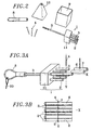
- the scheme of the figure 2 illustrates the components of the head according to a preferred embodiment of the invention.
- the stowage system comprises a support part 1 provided with several pins 2.
- Each brooch is provided with two perforations 5 diametrically opposite and coincident with perforations 7 made at the end of the tubes 6.
- the diameter of pins 2 is slightly lower than that of tubes 6 so as to that these pins can receive the end of a tube.
- the distance between two pins 2 is sufficient to make room for a tube 6. Indeed, as we will see it in the continuation it is not necessary to have as many tie down pins as there are tubes to stow since tubes can be interposed between the pins and be fixed with the tubes fitting the pin. This arrangement is illustrated by the detail of Figure 3B.
- Pins 2 are aligned on one side of the plate 11 of the part according to a plane or several planes parallel.
- the plate 11 is therefore the support for the pins of the room.
- the pins are removable.
- the plate includes threaded holes on the face intended to receive the pins chosen as required and screwed.
- Pins 2 can thus have diameters different adapted to the diameters of the tubes to be stowed, the threaded part of the pins can however have a single diameter which simplifies the design of the platinum.
- Figures 3C and 3D illustrate two examples arrangement leading respectively to an assembly planar for up to 4 tubes and one for one circular assembly for up to 7 tubes.
- Tablecloths of tubes can be mapped on the support piece with ease.
- the tubes present on a row are then fixed by a pin 4. Indeed, a pin 4 crosses each row of spindle and fixed the tubes which are on this row.
- the plate 11 is also the support for an element 3 for anchoring the traction rope 20.
- This element is consisting of a threaded rod 3 fixed to the plate 11 preferably along an axis passing through the center of the face on which it is fixed and parallel to the longitudinal axis X of the pins.
- the rod is threaded at both ends, one to be fixed on the plate of the support part and the other to be able to screw a ring 8 to which the traction rope 20.
- the plate also makes it possible to serve as a stop for a pin locking element 4.
- This element is constituted by an envelope 9 of shape and dimensions adapted to those of the turntable. This envelope is secured to the plate. So the deck cannot have rotational motion regardless of the envelope.
- the envelope 9 performs a self-locking of 4 pins and the plate.
- the plate has a shape parallelepiped and the envelope 9 also.
- the pull head further includes an element facilitating its movement in the pipe.
- This element consists of a conical piece 10, drilled in its center to be slid over the threaded rod 3. This piece 10 protects the clean edges of the plate 11 against any roughness of the pipe, limit the friction of the assembly on the pipe and press the envelope 9 against the plate 11.
- This frustoconical part 10 could for example be in low friction material, for example in Teflon.
- FIG. 5 shows a tool allowing tube preparation before securing to the head which has just been described.
- This tool is in the form of a box 30.
- This housing 30 has an insertion slot 31 of the tubes extending by a hollow cavity 32 extending substantially over the entire length of the housing, the bottom of this cavity constitutes a stop 320 for inserted tubes.
- a wall of the case perpendicular to the stop 320 has an opening 33 extending over the entire width of the wall. This opening is located above the stop and allows the tube alignment control.
- the housing has an orifice 34 on a wall perpendicular to the wall 300 including the window control 33. This orifice 34 allows the wick to pass a drill to pierce the tubes inserted in the housing.
- the housing also has on the wall 300 a groove 34 extending over the entire width of the housing whose bottom coincides with the lower plate of the cavity or is slightly below the latter.
- the groove allows sawing the tubes stored on the tray of the cavity, at the desired length relative to the holes made. This allows to have holes aligned and in correspondence with the orifices of the support part pins.
- This tool 30 makes it possible to prepare rapid of a group of tubes aligned on a plane. of the variants of the tool can of course be considered.
- the support part pins are inserted into some tubes of the group and the tubes of each row are fixed on the support piece by introducing a pin of the holes which are opposite on this row.
- the pins are held in place position thanks to the envelope 9 which is introduced from the side of the threaded rod, and which will also serve as protection for the end of the tubes.
- the room frustoconical 10 is then introduced around the rod threaded 3. Then the pulling ring 8 is screwed on this rod 3.
- the draw head does not depend on the number of tubes to be towed. Places can remain free if this number is less than the capacity of the head.
- the general shape of the head may be slightly different and the arrangement of the tubes may vary staying in the spirit of the invention.
- the plate comprises pins for securing the tubes. These pins could be replaced by partitions defining deep dwellings, each intended for receive a tube end.
Landscapes
- Laying Of Electric Cables Or Lines Outside (AREA)
- Hand Tools For Fitting Together And Separating, Or Other Hand Tools (AREA)
- Electric Cable Installation (AREA)
- Earth Drilling (AREA)
- Supports For Pipes And Cables (AREA)
Claims (13)
- Ziehkopf für Rohre mit Mitteln zum Anhängen eines Zugseils (20) und Mitteln zur Befestigung eines oder mehrerer Rohre (6) mit einem Halteteil (1) zur Handhabung des Endes von Rohren (6) in einer oder mehreren Reihen, dadurch gekennzeichnet, daß die Befestigungsmittel außerdem pro Reihe wenigstens ein Element zur Querfixierung der Rohre (6) aufweisen.
- Ziehkopf für Rohre nach Anspruch 1, dadurch gekennzeichnet, daß das Halteteil (1) zur Handhabung der Rohre eine Platine (11) aufweist, die an einer ihrer Seiten mit in einer oder mehreren Reihen ausgerichteten Spindeln (2) versehen ist, wobei die Spindeln (2) gemäß ein und derselben Achse pro Reihe diametral durchbohrt sind und die Fixierungselemente von Stiften (4) gebildet sind, wobei jeder Stift (4) zum Durchsetzen der Spindeln (2) einer Reihe und der durchbohrten Rohre dieser Reihe bestimmt ist, die von dem Teil getragen sind, um eine gleichzeitige Querblockierung mehrerer Rohre herzustellen.
- Ziehkopf für Rohre nach Anspruch 1 oder 2, dadurch gekennzeichnet, daß die Spindeln (2) abnehmbar sind und ihr Durchmesser verschieden sein kann.
- Ziehkopf für Rohre nach einem der vorangehenden Ansprüche, dadurch gekennzeichnet, daß die Stifte (4) verschiedene Längen haben können.
- Ziehkopf für Rohre nach Anspruch 2, dadurch gekennzeichnet, daß die Platine (11) mehrere Reihen von Spindeln (2) aufweist, die eine verschiedene Anzahl von Spindeln haben können.
- Ziehkopf für Rohre nach einem der vorangehenden Ansprüche, dadurch gekennzeichnet, daß die Befestigungsmittel eine Hülle (9) zur Blockierung der Platine (1) und der Stifte (4) aufweisen.
- Ziehkopf für Rohre nach einem der vorangehenden Ansprüche, dadurch gekennzeichnet, daß die Mittel zum Anhängen des Zugseils eine Gewindestange aufweisen, die an der Platine befestigt und in der Achse der Spindeln ausgerichtet ist.
- Ziehkopf für Rohre nach Anspruch 7, dadurch gekennzeichnet, daß die Mittel zum Anhängen des Zugseils einen Ring aufweisen, der mit einem Zylinder mit Gewinde versehen ist, der zum Anschrauben an der Stange bestimmt ist.
- Ziehkopf für Rohre nach einem der Ansprüche 7 oder 8, dadurch gekennzeichnet, daß sie einen Führungskonus aufweist, der sich vom Umfang der Platine bis zum Gewindebereich der Stange erstreckt.
- Ziehkopf für Rohre nach einem der vorangehenden Ansprüche, dadurch gekennzeichnet, daß die Gewindestange abnehmbar ist.
- Verfahren zum Ziehen von Rohren, welches das Befestigen eines oder mehrerer Rohre an einem Ziehkopf und das Anhängen eines Zugseils an dem Kopf umfaßt und im übrigen zuvor aufweist:und daßeine Maßnahme der Ausrichtung des Endes einer Reihe von Rohren mittels eines Richtwerkzeugs (30),eine Maßnahme der gleichzeitigen Durchbohrung der Rohre der Reihe gemäß einer zur Längsachse der Rohre querverlaufenden Achse mittels des Richtwerkzeugs (30),die Befestigung der Rohre an einem Ziehkopf nach einem der vorangehenden Ansprüche durchgeführt wird.
- Verfahren zum Einziehen von Rohren nach Anspruch 11, dadurch gekennzeichnet, daß die Maßnahme der Ausrichtung des Endes der Rohre umfaßt:das Einsetzen der Enden der Gruppe von Rohren in das Werkzeug (30), wobei das Werkzeug (30) einen Blindsitz aufweist, der an einem Einführungsschlitz mündet, um das Ende der in einer Reihe angeordneten Rohre aufzunehmen,das gleichzeitige Abschneiden aller Enden der Rohre durch eine im Werkzeug oberhalb der Reihe von Rohren ausgebildete Nut.
- Verfahren zum Einziehen von Rohren nach Anspruch 11, dadurch gekennzeichnet, daß die Maßnahme der Durchbohrung der Rohre die gleichzeitige Durchbohrung der Rohre einer in das Werkzeug (30) eingeführten Gruppe von Rohren umfaßt, wobei das Werkzeug (30) eine oder mehrere Bohrungen für den Durchtritt einer Bohrmaschine an mindestens einer Seite aufweist, die zur Ebene der Reihe von Rohren senkrecht ist.
Applications Claiming Priority (3)
| Application Number | Priority Date | Filing Date | Title |
|---|---|---|---|
| FR0102521 | 2001-02-23 | ||
| FR0102521A FR2821496B1 (fr) | 2001-02-23 | 2001-02-23 | Tete de tirage de tubes et procede de tirage de tubes en conduites |
| PCT/FR2002/000644 WO2002069467A1 (fr) | 2001-02-23 | 2002-02-21 | Tete de tirage de tubes et procede de tirage de tubes en conduites |
Publications (2)
| Publication Number | Publication Date |
|---|---|
| EP1362397A1 EP1362397A1 (de) | 2003-11-19 |
| EP1362397B1 true EP1362397B1 (de) | 2004-10-13 |
Family
ID=8860394
Family Applications (1)
| Application Number | Title | Priority Date | Filing Date |
|---|---|---|---|
| EP02704869A Expired - Lifetime EP1362397B1 (de) | 2001-02-23 | 2002-02-21 | Ziehkopf für rohre und verfahren zum ziehen von rohren in leitungen |
Country Status (6)
| Country | Link |
|---|---|
| EP (1) | EP1362397B1 (de) |
| AT (1) | ATE279802T1 (de) |
| DE (1) | DE60201578T2 (de) |
| ES (1) | ES2231670T3 (de) |
| FR (1) | FR2821496B1 (de) |
| WO (1) | WO2002069467A1 (de) |
Family Cites Families (5)
| Publication number | Priority date | Publication date | Assignee | Title |
|---|---|---|---|---|
| US3868191A (en) * | 1973-11-19 | 1975-02-25 | Sr Lloyd H King | Multiple pipe pulling device |
| DE2840711C2 (de) * | 1978-09-19 | 1980-11-20 | Thyssen Plastik Anger Kg, 8000 Muenchen | Einzugvorrichtung für Kabel |
| DE8520355U1 (de) * | 1985-07-13 | 1985-09-12 | Peter Lancier Maschinenbau-Hafenhütte GmbH & Co KG, 4400 Münster | Ziehkopf für Kunststoff-Mehrfachrohre |
| FR2596924B1 (fr) * | 1986-04-08 | 1988-05-20 | Fernandez Manuel | Dispositif de tirage de tubes en materiau deformable |
| DE8908918U1 (de) * | 1989-07-21 | 1989-11-02 | Peter Lancier Maschinenbau-Hafenhütte GmbH & Co KG, 4400 Münster | Ziehkopf für Kunststoff-Mehrfachrohre |
-
2001
- 2001-02-23 FR FR0102521A patent/FR2821496B1/fr not_active Expired - Fee Related
-
2002
- 2002-02-21 AT AT02704869T patent/ATE279802T1/de not_active IP Right Cessation
- 2002-02-21 DE DE60201578T patent/DE60201578T2/de not_active Expired - Fee Related
- 2002-02-21 EP EP02704869A patent/EP1362397B1/de not_active Expired - Lifetime
- 2002-02-21 WO PCT/FR2002/000644 patent/WO2002069467A1/fr not_active Ceased
- 2002-02-21 ES ES02704869T patent/ES2231670T3/es not_active Expired - Lifetime
Also Published As
| Publication number | Publication date |
|---|---|
| ATE279802T1 (de) | 2004-10-15 |
| FR2821496B1 (fr) | 2004-12-10 |
| WO2002069467A1 (fr) | 2002-09-06 |
| ES2231670T3 (es) | 2005-05-16 |
| EP1362397A1 (de) | 2003-11-19 |
| DE60201578D1 (de) | 2004-11-18 |
| DE60201578T2 (de) | 2005-11-10 |
| FR2821496A1 (fr) | 2002-08-30 |
Similar Documents
| Publication | Publication Date | Title |
|---|---|---|
| EP1224719B1 (de) | Führungsvorrichtung wenigstens eines langgestreckten biegsamen elements, wie kabel oder ähnliches, mit vorwiegend geschlossener kontur | |
| EP2115837B1 (de) | Vorrichtung zur befestigung einer garn-kabelbahn | |
| FR2728079A1 (fr) | Dispositif de maintien d'au moins un cable a fibres optiques et boitier d'epissurage en faisant application | |
| FR3004233A1 (fr) | Dispositif pour la fixation, sur une paroi, d'un raccord de canalisation | |
| EP1362397B1 (de) | Ziehkopf für rohre und verfahren zum ziehen von rohren in leitungen | |
| FR2958811A1 (fr) | Support pour goulotte de chemin de cables, chemin de cables comprenant un tel support et methode de montage d'une goulotte sur un tel support | |
| CA2296201C (fr) | Element de connecteur pour fibre optique | |
| EP0889844B1 (de) | Hebevorrichtung von einem elektrospindel einer hochgeschwindigkeitsbearbeitungswerkzeugmaschine | |
| FR2853463A1 (fr) | Console de support de chemin de cables | |
| EP2993151A1 (de) | Hochleistungs-trommel | |
| EP3408570B1 (de) | Spule zur handhabung der überlänge eines elektrischen kabels | |
| FR3024596A1 (fr) | Dispositif d’adjonction pour une prise | |
| EP1376808A1 (de) | Vorrichtung zur Befestigung eines Kabelführungskanals auf einem Träger und Anordnung mit einem Kanal und einer solchen Vorrichtung | |
| WO2023099337A1 (fr) | Dispositif d'assistance à l'aiguillage pour la pose d'une fibre optique dans une structure | |
| EP4528346B1 (de) | Anschlussdose mit abnehmbarem element zur aufbewahrung einer überlänge eines kabels | |
| EP1825313B1 (de) | Verfahren und einrichtung zur fixierung von stützröhrchen für telekommunikationskabel auf einem träger | |
| FR3115612A1 (fr) | Coffret comprenant un dispositif de fixation interne avec raccords optiques | |
| FR2691226A1 (fr) | Dispositif d'ancrage latéral de barres, notamment de tubes d'échafaudage. | |
| BE1029684B1 (fr) | Pion d'arrimage pour câble, en particulier pour câble optique | |
| FR3163782A1 (fr) | Support d’interconnexion de câbles, notamment pour équipement aéronautique | |
| FR3008495A1 (fr) | Procede de mise en place d’un systeme de traction sur un cable a fibres optiques | |
| FR3141818A1 (fr) | Connecteur de mise à la terre d’au moins un fil de terre | |
| FR2716768A1 (fr) | Elément de montage d'accessoire sur une paroi en treillis. | |
| FR2835360A1 (fr) | Outil d'engainage d'au moins un cable dans une gaine fendue longitudinalement, et dispositif d'engainage comportant un tel outil | |
| FR2813626A1 (fr) | Dispositif d'assemblage et de serrage de banches face a face |
Legal Events
| Date | Code | Title | Description |
|---|---|---|---|
| PUAI | Public reference made under article 153(3) epc to a published international application that has entered the european phase |
Free format text: ORIGINAL CODE: 0009012 |
|
| 17P | Request for examination filed |
Effective date: 20030630 |
|
| AK | Designated contracting states |
Kind code of ref document: A1 Designated state(s): AT BE CH CY DE DK ES FI FR GB GR IE IT LI LU MC NL PT SE TR |
|
| AX | Request for extension of the european patent |
Extension state: AL LT LV MK RO SI |
|
| RIN1 | Information on inventor provided before grant (corrected) |
Inventor name: LE GOFF, GERARD Inventor name: CAMPION, JEAN-LUC Inventor name: MIGNON, PIERRE |
|
| GRAP | Despatch of communication of intention to grant a patent |
Free format text: ORIGINAL CODE: EPIDOSNIGR1 |
|
| GRAS | Grant fee paid |
Free format text: ORIGINAL CODE: EPIDOSNIGR3 |
|
| GRAA | (expected) grant |
Free format text: ORIGINAL CODE: 0009210 |
|
| AK | Designated contracting states |
Kind code of ref document: B1 Designated state(s): AT BE CH CY DE DK ES FI FR GB GR IE IT LI LU MC NL PT SE TR |
|
| PG25 | Lapsed in a contracting state [announced via postgrant information from national office to epo] |
Ref country code: IT Free format text: LAPSE BECAUSE OF FAILURE TO SUBMIT A TRANSLATION OF THE DESCRIPTION OR TO PAY THE FEE WITHIN THE PRESCRIBED TIME-LIMIT;WARNING: LAPSES OF ITALIAN PATENTS WITH EFFECTIVE DATE BEFORE 2007 MAY HAVE OCCURRED AT ANY TIME BEFORE 2007. THE CORRECT EFFECTIVE DATE MAY BE DIFFERENT FROM THE ONE RECORDED. Effective date: 20041013 Ref country code: GB Free format text: LAPSE BECAUSE OF FAILURE TO SUBMIT A TRANSLATION OF THE DESCRIPTION OR TO PAY THE FEE WITHIN THE PRESCRIBED TIME-LIMIT Effective date: 20041013 Ref country code: IE Free format text: LAPSE BECAUSE OF FAILURE TO SUBMIT A TRANSLATION OF THE DESCRIPTION OR TO PAY THE FEE WITHIN THE PRESCRIBED TIME-LIMIT Effective date: 20041013 Ref country code: TR Free format text: LAPSE BECAUSE OF FAILURE TO SUBMIT A TRANSLATION OF THE DESCRIPTION OR TO PAY THE FEE WITHIN THE PRESCRIBED TIME-LIMIT Effective date: 20041013 Ref country code: FI Free format text: LAPSE BECAUSE OF FAILURE TO SUBMIT A TRANSLATION OF THE DESCRIPTION OR TO PAY THE FEE WITHIN THE PRESCRIBED TIME-LIMIT Effective date: 20041013 Ref country code: AT Free format text: LAPSE BECAUSE OF FAILURE TO SUBMIT A TRANSLATION OF THE DESCRIPTION OR TO PAY THE FEE WITHIN THE PRESCRIBED TIME-LIMIT Effective date: 20041013 Ref country code: NL Free format text: LAPSE BECAUSE OF FAILURE TO SUBMIT A TRANSLATION OF THE DESCRIPTION OR TO PAY THE FEE WITHIN THE PRESCRIBED TIME-LIMIT Effective date: 20041013 |
|
| REG | Reference to a national code |
Ref country code: GB Ref legal event code: FG4D Free format text: NOT ENGLISH |
|
| REG | Reference to a national code |
Ref country code: CH Ref legal event code: EP |
|
| REG | Reference to a national code |
Ref country code: IE Ref legal event code: FG4D Free format text: FRENCH |
|
| REF | Corresponds to: |
Ref document number: 60201578 Country of ref document: DE Date of ref document: 20041118 Kind code of ref document: P |
|
| PG25 | Lapsed in a contracting state [announced via postgrant information from national office to epo] |
Ref country code: GR Free format text: LAPSE BECAUSE OF FAILURE TO SUBMIT A TRANSLATION OF THE DESCRIPTION OR TO PAY THE FEE WITHIN THE PRESCRIBED TIME-LIMIT Effective date: 20050113 Ref country code: DK Free format text: LAPSE BECAUSE OF FAILURE TO SUBMIT A TRANSLATION OF THE DESCRIPTION OR TO PAY THE FEE WITHIN THE PRESCRIBED TIME-LIMIT Effective date: 20050113 Ref country code: SE Free format text: LAPSE BECAUSE OF FAILURE TO SUBMIT A TRANSLATION OF THE DESCRIPTION OR TO PAY THE FEE WITHIN THE PRESCRIBED TIME-LIMIT Effective date: 20050113 |
|
| PG25 | Lapsed in a contracting state [announced via postgrant information from national office to epo] |
Ref country code: CY Free format text: LAPSE BECAUSE OF FAILURE TO SUBMIT A TRANSLATION OF THE DESCRIPTION OR TO PAY THE FEE WITHIN THE PRESCRIBED TIME-LIMIT Effective date: 20050221 Ref country code: LU Free format text: LAPSE BECAUSE OF NON-PAYMENT OF DUE FEES Effective date: 20050221 |
|
| PG25 | Lapsed in a contracting state [announced via postgrant information from national office to epo] |
Ref country code: MC Free format text: LAPSE BECAUSE OF NON-PAYMENT OF DUE FEES Effective date: 20050228 Ref country code: BE Free format text: LAPSE BECAUSE OF NON-PAYMENT OF DUE FEES Effective date: 20050228 |
|
| LTIE | Lt: invalidation of european patent or patent extension |
Effective date: 20041013 |
|
| NLV1 | Nl: lapsed or annulled due to failure to fulfill the requirements of art. 29p and 29m of the patents act | ||
| GBV | Gb: ep patent (uk) treated as always having been void in accordance with gb section 77(7)/1977 [no translation filed] |
Effective date: 20041013 |
|
| REG | Reference to a national code |
Ref country code: ES Ref legal event code: FG2A Ref document number: 2231670 Country of ref document: ES Kind code of ref document: T3 |
|
| REG | Reference to a national code |
Ref country code: IE Ref legal event code: FD4D |
|
| PLBE | No opposition filed within time limit |
Free format text: ORIGINAL CODE: 0009261 |
|
| STAA | Information on the status of an ep patent application or granted ep patent |
Free format text: STATUS: NO OPPOSITION FILED WITHIN TIME LIMIT |
|
| BERE | Be: lapsed |
Owner name: FRANCE TELECOM SA Effective date: 20050228 |
|
| 26N | No opposition filed |
Effective date: 20050714 |
|
| PG25 | Lapsed in a contracting state [announced via postgrant information from national office to epo] |
Ref country code: CH Free format text: LAPSE BECAUSE OF NON-PAYMENT OF DUE FEES Effective date: 20060228 Ref country code: LI Free format text: LAPSE BECAUSE OF NON-PAYMENT OF DUE FEES Effective date: 20060228 |
|
| REG | Reference to a national code |
Ref country code: CH Ref legal event code: PL |
|
| PGFP | Annual fee paid to national office [announced via postgrant information from national office to epo] |
Ref country code: DE Payment date: 20070131 Year of fee payment: 6 |
|
| PGFP | Annual fee paid to national office [announced via postgrant information from national office to epo] |
Ref country code: ES Payment date: 20070209 Year of fee payment: 6 |
|
| BERE | Be: lapsed |
Owner name: S.A. *FRANCE TELECOM Effective date: 20050228 |
|
| PG25 | Lapsed in a contracting state [announced via postgrant information from national office to epo] |
Ref country code: PT Free format text: LAPSE BECAUSE OF NON-PAYMENT OF DUE FEES Effective date: 20050313 |
|
| PGFP | Annual fee paid to national office [announced via postgrant information from national office to epo] |
Ref country code: FR Payment date: 20070227 Year of fee payment: 6 |
|
| REG | Reference to a national code |
Ref country code: FR Ref legal event code: ST Effective date: 20081031 |
|
| PG25 | Lapsed in a contracting state [announced via postgrant information from national office to epo] |
Ref country code: DE Free format text: LAPSE BECAUSE OF NON-PAYMENT OF DUE FEES Effective date: 20080902 |
|
| PG25 | Lapsed in a contracting state [announced via postgrant information from national office to epo] |
Ref country code: FR Free format text: LAPSE BECAUSE OF NON-PAYMENT OF DUE FEES Effective date: 20080229 |
|
| REG | Reference to a national code |
Ref country code: ES Ref legal event code: FD2A Effective date: 20080222 |
|
| PG25 | Lapsed in a contracting state [announced via postgrant information from national office to epo] |
Ref country code: ES Free format text: LAPSE BECAUSE OF NON-PAYMENT OF DUE FEES Effective date: 20080222 |