EP1362384B1 - Brennstoffzellensystem - Google Patents
Brennstoffzellensystem Download PDFInfo
- Publication number
- EP1362384B1 EP1362384B1 EP02708192A EP02708192A EP1362384B1 EP 1362384 B1 EP1362384 B1 EP 1362384B1 EP 02708192 A EP02708192 A EP 02708192A EP 02708192 A EP02708192 A EP 02708192A EP 1362384 B1 EP1362384 B1 EP 1362384B1
- Authority
- EP
- European Patent Office
- Prior art keywords
- fuel cell
- catalyst
- cathode
- porous layer
- alcohol
- Prior art date
- Legal status (The legal status is an assumption and is not a legal conclusion. Google has not performed a legal analysis and makes no representation as to the accuracy of the status listed.)
- Expired - Lifetime
Links
Images

Classifications
-
- H—ELECTRICITY
- H01—ELECTRIC ELEMENTS
- H01M—PROCESSES OR MEANS, e.g. BATTERIES, FOR THE DIRECT CONVERSION OF CHEMICAL ENERGY INTO ELECTRICAL ENERGY
- H01M8/00—Fuel cells; Manufacture thereof
- H01M8/02—Details
-
- H—ELECTRICITY
- H01—ELECTRIC ELEMENTS
- H01M—PROCESSES OR MEANS, e.g. BATTERIES, FOR THE DIRECT CONVERSION OF CHEMICAL ENERGY INTO ELECTRICAL ENERGY
- H01M8/00—Fuel cells; Manufacture thereof
- H01M8/06—Combination of fuel cells with means for production of reactants or for treatment of residues
- H01M8/0662—Treatment of gaseous reactants or gaseous residues, e.g. cleaning
-
- H—ELECTRICITY
- H01—ELECTRIC ELEMENTS
- H01M—PROCESSES OR MEANS, e.g. BATTERIES, FOR THE DIRECT CONVERSION OF CHEMICAL ENERGY INTO ELECTRICAL ENERGY
- H01M8/00—Fuel cells; Manufacture thereof
- H01M8/10—Fuel cells with solid electrolytes
- H01M8/1009—Fuel cells with solid electrolytes with one of the reactants being liquid, solid or liquid-charged
-
- Y—GENERAL TAGGING OF NEW TECHNOLOGICAL DEVELOPMENTS; GENERAL TAGGING OF CROSS-SECTIONAL TECHNOLOGIES SPANNING OVER SEVERAL SECTIONS OF THE IPC; TECHNICAL SUBJECTS COVERED BY FORMER USPC CROSS-REFERENCE ART COLLECTIONS [XRACs] AND DIGESTS
- Y02—TECHNOLOGIES OR APPLICATIONS FOR MITIGATION OR ADAPTATION AGAINST CLIMATE CHANGE
- Y02E—REDUCTION OF GREENHOUSE GAS [GHG] EMISSIONS, RELATED TO ENERGY GENERATION, TRANSMISSION OR DISTRIBUTION
- Y02E60/00—Enabling technologies; Technologies with a potential or indirect contribution to GHG emissions mitigation
- Y02E60/30—Hydrogen technology
- Y02E60/50—Fuel cells
Definitions
- the invention relates to a fuel cell system, in particular a fuel cell system comprising at least one direct methanol fuel cell.
- DE 199 21 816 C1 discloses a fuel cell system comprising individual fuel cells.
- the system further includes a disposal device for receiving the waste products formed by the operation of the fuel cells.
- a disposal device for receiving the waste products formed by the operation of the fuel cells.
- This is in particular a filter device and an ion exchanger device.
- a disadvantage of this system is that the waste products are first collected within the system and removed from the system only at a certain time.
- US Pat. No. 6,124,053 A discloses a fuel cell system in which the anode exhaust gases are catalytically combusted.
- the anode exhaust gas is passed together with a gaseous oxidizing agent via a porous catalyst which is arranged at the inlet region of the cathode space.
- the burnt exhaust gas is then optionally supplied to the cathode with further carrier gas or oxidant.
- a catalytic afterburning is known from US 5,981,096 A.
- all of the cathode exhaust gas is passed over a combustion catalyst.
- the object of the invention is to provide a fuel cell system in which an undesirable discharge of alcohol is avoided.
- the object is achieved by a fuel cell system according to the main claim and by a method for operating a fuel cell system according to the independent claim.
- Advantageous embodiments of the fuel cell system and the method can be found in the respective dependent claims.
- the fuel cell system according to claim 1 comprises at least one fuel cell and has a catalyst in the exhaust gas region of the fuel cell system.
- the exhaust area of a fuel cell system is understood to be the area in which exhaust gases form and are passed on.
- the cathode compartment as well as the exhaust gas lines are counted from the cathode compartment.
- exhaust pipes also include manifolds for the exhaust gases in addition to the individual cathode or anode walls of the individual fuel cells.
- a catalyst in the context of this invention which is arranged in this exhaust area, is not to be understood in the membrane electrode assembly of a fuel cell located conventional catalyst of a fuel cell.
- the fuel cell system disclosed in claim 1 also has, as it were, an additional catalyst.
- An advantageous embodiment of the fuel cell system according to claim 2 has at least one direct alcohol fuel cell.
- an alcohol-containing exhaust gas is formed in the anode compartment. Furthermore, as a rule, parts of the alcohol from the anode compartment pass through the membrane through the membrane into the cathode compartment and, as a rule, also form alcohol-containing exhaust gases there.
- the catalyst located in the exhaust space of a fuel cell system causes a catalytic conversion of the alcohol and thus reduces the risk of alcohol discharge from the fuel cell system.
- the catalyst is arranged according to claim 3 directly in the cathode compartment of a fuel cell, there to convert the alcohol immediately.
- the catalyst in the cathode compartment is capable of oxidizing alcohol.
- an oxidizing agent in particular oxygen, which promotes the oxidative conversion of alcohol in the presence of the catalyst in water and carbon dioxide.
- oxygen which promotes the oxidative conversion of alcohol in the presence of the catalyst in water and carbon dioxide.
- other can also By-products that arise during operation of a fuel cell are oxidatively converted with this catalyst. These include formaldehyde, methyl formate or formic acid.
- a particular embodiment according to claim 5 provides the catalyst in the form of a porous layer.
- the porous layer can consist entirely of catalyst material.
- the porous layer can also be coated only with the catalyst material in a suitable manner in order to save expensive catalyst material with virtually the same effect.
- a catalytically active porous layer has advantages in the reaction of gaseous products, in this case the alcohol, since the catalytically active surface in a porous layer is regularly particularly large.
- a porous layer within the cathode space is arranged parallel to the electrode surface.
- the water formed in the oxidation of the oxidizing agent at the cathode and also the water diffusing through the membrane by permeation from the anode side advantageously remain directly at the cathode.
- the resulting water at the cathode in the form of drops and thus does not reach the porous layer. This ensures that the porous layer itself remains as dry as possible.
- the activity of the catalyst on the porous layer can be effectively increased.
- the catalyst is arranged in the form of a porous layer as a partition wall between the oxidant inlet and the exhaust outlet within the cathode space in order to achieve that the entire exhaust gas flow from the cathode space first passes through the catalyst.
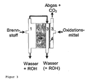
- An advantageous embodiment of the fuel cell system further provides an exhaust pipe from an anode compartment into a cathode compartment, the mouth of the exhaust conduit being provided from the anode compartment into the space between the cathode and the porous catalyst-containing layer.
- the entire exhaust gas flow from the anode compartment which may comprise gaseous, unreacted alcohol, is brought into contact with the catalyst.
- the catalyst can advantageously convert both the anode-side, and the cathode-side resulting gaseous alcohol in the exhaust gas.
- the alcohol can be converted into harmless human water and CO 2 .
- exhaust gas formed in a fuel cell system is fed to a catalyst.
- the exhaust gas of each fuel cell of the fuel cell system can be individually supplied to a catalyst, or else all exhaust gas streams are first collected and then fed to a catalyst.
- the exhaust gas of a single fuel cell formed on the cathode side is fed to a catalyst located in the cathode compartment.
- a further embodiment of the method provides, first to guide the exhaust gas formed on the anode side into a cathode space, and then to supply a catalyst together with the exhaust gas additionally formed there.
- this catalyst is also arranged directly in the cathode compartment.
- the method is particularly effective when the exhaust gas streams are fed to the catalyst in the form of a catalytically active porous layer, in particular a filter, or through which this filter flows. If the filter is arranged completely in an exhaust pipe or an exhaust space, it is ensured that the entire exhaust gas must pass through this filter before it enters the environment. Such an arrangement, or such a method, advantageously effects the greatest possible conversion of the exhaust gases of a fuel cell system having alcohol, and thus the reduction or prevention of an alcohol discharge into the environment.
- the invention further causes the carbon dioxide emissions by the additional convection improves the water discharge.
- the additional catalytically active layer is a filter that keeps contaminants from the ambient air from the cathode (air electrode).
- the additional porous layer has a favorable effect on the thermal conditions within the fuel cell system because it prevents too much evaporation of the water on the cathode side. The layer regularly prevents excessive air convection, which in turn leads to cooling due to evaporation of water.
- FIG. 1 shows a fuel cell according to the prior art with an electrode-electrolyte unit 2 and an anode compartment 1 and a cathode compartment 3.
- an alcohol-water mixture is used as fuel.
- the depleted alcohol-water mixture leaves the anode compartment 1.
- Gaseous CO 2 and gaseous alcohol reach the environment via the anode exhaust gas line.
- the alcohol permeation alcohol passes from the anode compartment 1 in the cathode compartment 3. Here it is withdrawn as a water-alcohol mixture and / or also discharged in the gaseous state via the cathode exhaust gas into the environment.
- an additional catalyst according to the invention in the exhaust gas region is arranged here as a porous, catalytically active layer 4 in the cathode compartment 3.
- the supplied oxidant flows through the catalyst 4 and is filtered at the same time.
- Alcohol diffused through the electrolyte into the cathode space 3 is converted in gaseous form to the catalyst 4 and leaves the cathode space 3, for example, as water and CO 2 .
- the exhaust gas flow from the anode compartment 1 containing alcohol is first introduced into the cathode compartment 3, where it passes through the porous, catalytically active layer 4.
- the alcohol is regularly converted into CO 2 and water, so that almost alcohol-free exhaust gas exits the fuel cell.
Landscapes
- Life Sciences & Earth Sciences (AREA)
- Engineering & Computer Science (AREA)
- Manufacturing & Machinery (AREA)
- Sustainable Development (AREA)
- Sustainable Energy (AREA)
- Chemical & Material Sciences (AREA)
- Chemical Kinetics & Catalysis (AREA)
- Electrochemistry (AREA)
- General Chemical & Material Sciences (AREA)
- Fuel Cell (AREA)
- Inert Electrodes (AREA)
Description
- Die Erfindung betrifft ein Brennstoffzellensystem, insbesondere ein Brennstoffzellensystem umfassend wenigstens eine Direkt-Methanol-Brennstoffzelle.
- Aus DE 199 21 816 C1 ist ein Brennstoffzellensystem, umfassend einzelne Brennstoffzellen, bekannt. Das System weist weiterhin eine Entsorgungsvorrichtung zur Aufnahme der durch den Betrieb der Brennstoffzellen gebildeten Abfallprodukte auf. Dies ist insbesondere eine Filtereinrichtung und eine Ionenaustauschereinrichtung. Durch Filtereinrichtungen ist es vorteilhaft möglich, die entstehenden Abfallprodukte voneinander zu trennen und getrennt zu sammeln, was die spätere Entsorgung erleichtert. Dies kann beispielsweise zur Umwandlung von an der Anode entstehendem gasförmigem CO2 zu festem Karbonat genutzt werden.
- Bei der in DE 199 21 816 C offenbarten Ionenaustauschereinrichtung als Entsorgungsvorrichtung wird zunächst ein Abfallprodukt umgewandelt und anschließend in einer Aufnahmeeinrichtung gesammelt. Bei dem in DE 199 21 816 C1 beschriebenen Brennstoffzellensystem kann die Brennstoffseite des Systems so vorteilhaft völlig entkoppelt von der Umwelt betrieben werden.
- Nachteilig bei diesem System ist jedoch, daß die Abfallprodukte innerhalb des Systems zunächst gesammelt und erst zu einem bestimmten Zeitpunkt aus dem System entnommen werden.
- Aus US 6,124,053 A ist ein Brennstoffzellensystem bekannt, bei dem die Anodenabgase katalytisch verbrannt werden. Das Anodenabgas wird dabei zusammen mit einem gasförmigen Oxidationsmittel über einen porösen Katalysator geleitet, der am Eingangsbereich des Kathodenraums angeordnet ist. Das verbrannte Abgas wird anschließend ggf. mit weiterem Trägergas oder Oxidationsmittel der Kathode zugeführt.
Eine katalytische Nachverbrennung ist aus US 5,981,096 A bekannt. Hier wird bei einem mit Alkohol arbeitendem Brennstoffzellensystem das gesamte Kathodenabgas über einen Verbrennungskatalysator geleitet. - Die Aufgabe der Erfindung ist es, ein Brennstoffzellensystem zu schaffen, bei welchem ein unerwünschter Austrag an Alkohol vermieden wird.
Die Aufgabe wird gelöst durch ein Brennstoffzellensystem gemäß Hauptanspruch sowie durch ein Verfahren zum Betreiben eines Brennstoffzellensystems gemäß dem Nebenanspruch. Vorteilhafte Ausführungsformen des Brennstoffzellensystems und des Verfahren sind den jeweils rückbezogenen Ansprüchen zu entnehmen. - Das Brennstoffzellensystem nach Anspruch 1 umfaßt wenigstens eine Brennstoffzelle und weist im Abgasbereich des Brennstoffzellensystems einen Katalysator auf. Unter dem Abgasbereich eines Brennstoffzellensystems ist der Bereich zu verstehen, in dem sich Abgase bilden und weitergeleitet werden. Innerhalb einer Brennstoffzelle zählt dazu der Kathodenraum sowie die Abgasleitungen vom Kathodenraum aus. Bei einem Brennstoffzellensystem, umfassend mehrere Brennstoffzellen, gehören zu einem Abgasbereich neben den einzelnen Kathoden- bzw. Anodenraümen der einzelnen Brennstoffzellen auch Sammelleitungen für die Abgase.
- Als Katalysator im Sinne dieser Erfindung, der in diesem Abgasbereich angeordnet ist, ist nicht der in der Membran-Elektrodenanordnung einer Brennstoffzelle befindliche übliche Katalysator einer Brennstoffzelle zu verstehen. Das in Anspruch 1 offenbarte Brennstoffzellensystem weist sozusagen darüber hinaus einen zusätzlichen Katalysator auf.
Eine vorteilhafte Ausgestaltung des Brennstoffzellensystems gemäß Anspruch 2 weist mindestens eine Direkt-Alkohol-Brennstoffzelle auf. - Bei einer Direkt-Alkohol-Brennstoffzelle bildet sich im Anodenraum ein Alkohol aufweisendes Abgas aus. Weiterhin gelangen im Regelfall Teile des Alkohols aus dem Anodenraum durch die Alkoholpermeation durch die Membran in den Kathodenraum und bilden auch dort in der Regel Alkohol aufweisende Abgase. Der im Abgasraum eines Brennstoffzellensystems befindliche Katalysator bewirkt eine katalytische Umsetzung des Alkohols und verringert somit die Gefahr des Alkoholaustrags aus dem Brennstoffzellensystem.
- Vorteilhaft ist der Katalysator nach Anspruch 3 direkt im Kathodenraum einer Brennstoffzelle angeordnet, um dort den Alkohol sofort umzuwandeln.
- Gemäß Anspruch 4 ist der Katalysator im Kathodenraum in der Lage, Alkohol zu oxidieren. Vorteilhaft befindet sich im Kathodenraum ein Oxidationsmittel, insbesondere Sauerstoff, welcher die oxidative Umwandlung von Alkohol in Anwesenheit des Katalysators in Wasser und Kohlendioxid fördert. Vorteilhaft können auch weitere Nebenprodukte, die während des Betriebs einer Brennstoffzelle entstehen, oxidativ mit diesem Katalysator umgewandelt werden. Dazu gehören u. a. Formaldehyd, Methylformiat oder auch Ameisensäure.
- Eine besondere Ausgestaltung nach Anspruch 5 sieht den Katalysator in Form einer porösen Schicht vor. Dabei kann die poröse Schicht vollständig aus Katalysatormaterial bestehen. Vorteilhaft kann die poröse Schicht aber auch nur mit dem Katalysatormaterial in einer geeigneten Weise beschichtet sein, um bei nahezu gleicher Wirkung teures Katalysatormaterial einzusparen. Eine katalytisch aktive poröse Schicht weist Vorteile bei der Umsetzung gasförmiger Produkte, in diesem Fall des Alkohols auf, da die katalytisch aktive Fläche in einer porösen Schicht regelmäßig besonders groß ist.
- Vorteilhaft wird eine poröse Schicht innerhalb des Kathodenraums parallel zur Elektrodenoberfläche angeordnet. Dadurch entsteht zwischen der Kathode und der katalytisch aktiven Schicht ein Luftraum, der zugleich als Wasserabscheider fungiert. Das bei der Oxidation des Oxidationsmittels an der Kathode entstehende Wasser und auch das durch Permeation durch die Membran diffundierende Wasser von der Anodenseite verbleibt vorteilhaft direkt an der Kathode. Beispielsweise läuft das entstehende Wasser an der Kathode in Tropfenform ab und erreicht somit nicht die poröse Schicht. Dadurch wird erreicht, daß die poröse Schicht selbst möglichst trocken bleibt. Die Aktivität des Katalysators auf der porösen Schicht kann so wirksam erhöht werden.
- In einer weiteren Ausgestaltung wird der Katalysator in Form einer porösen Schicht als Trennwand zwischen Oxidationsmitteleinlaß und Abgasauslaß innerhalb des Kathodenraums angeordnet, um zu erzielen, daß der gesamte Abgasstrom aus dem Kathodenraum zunächst den Katalysator passiert.
- Eine vorteilhafte Ausgestaltung des Brennstoffzellensystems sieht weiterhin eine Abgasleitung von einem Anodenraum in einen Kathodenraum vor, wobei die Mündung der Abgasleitung aus dem Anodenraum in den Raum zwischen Kathode und poröser, Katalysator aufweisender Schicht vorgesehen ist.
Damit wird auch der gesamte Abgasstrom aus dem Anodenraum, der gasförmigen, nicht umgesetzten Alkohol aufweisen kann, in Kontakt mit dem Katalysator gebracht. Damit vermag der Katalysator vorteilhaft sowohl den anodenseitig, als auch den kathodenseitig anfallenden gasförmigen Alkohol im Abgas umzuwandeln. Insbesondere kann der Alkohol unter geeigneten Bedingungen in für den Menschen unschädliches Wasser und CO2 umgewandelt werden. - Bei dem erfindungsgemäßen Verfahren nach Anspruch 9 wird in einem Brennstoffzellensystem gebildetes Abgas einem Katalysator zugeführt. Dabei kann das Abgas einer jeden Brennstoffzelle des Brennstoffzellensystems einzeln einem Katalysator zugeführt werden, oder aber auch alle Abgasströme zunächst gesammelt und anschließend einem Katalysator zugeführt werden.
- Vorteilhaft wird das kathodenseitig gebildete Abgas einer einzelnen Brennstoffzelle einem im Kathodenraum befindlichen Katalysator zugeführt.
- Eine weitere Ausgestaltung des Verfahrens sieht vor, zunächst das anodenseitig gebildete Abgas in einen Kathodenraum zu leiten, und dann zusammen mit dem dort zusätzlich gebildeten Abgas einem Katalysator zuzuführen. Insbesondere ist auch dieser Katalysator direkt im Kathodenraum angeordnet.
- Besonders effektiv gestaltet sich das Verfahren, wenn die Abgasströme dem Katalysator in Form einer katalytisch aktiven porösen Schicht, insbesondere einem Filter, zugeführt werden, bzw. diesen Filter durchströmen. Sofern der Filter vollständig in einer Abgasleitung bzw. einem Abgasraum angeordnet ist, ist gewährleistet, daß das gesamte Abgas diesen Filter passieren muß, bevor es in die Umgebung gelangt. Eine solche Anordnung, bzw. ein solches Verfahren, bewirkt vorteilhaft eine größtmögliche Umsetzung der Alkohol aufweisenden Abgase eines Brennstoffzellensystems und damit die Verringerung bzw. Verhinderung eines Alkoholaustrages in die Umgebung.
- Die Erfindung bewirkt weiterhin, daß der Kohlendioxidausstoß durch die zusätzliche Konvektion den Wasseraustrag verbessert. Außerdem stellt die zusätzliche katalytisch aktive Schicht einen Filter dar, der Verunreinigungen aus der Umgebungsluft von der Kathode (Luftelektrode) fernhält. Weiterhin wirkt sich die zusätzliche poröse Schicht günstig auf die thermischen Verhältnisse innerhalb des Brennstoffzellensystems aus, da sie eine zu große Verdunstung des Wassers auf der Kathodenseite verhindert. Die Schicht verhindert regelmäßig eine zu große Luftkonvektion, die wiederum zur Auskühlung durch Wasserverdunstung führt.
- Im folgenden wird die Erfindung anhand von drei Figuren näher erläutert.
- Es zeigen
- Figur 1:
- Brennstoffzelle mit Anoden- und Kathodenraum gemäß Stand der Technik.
- Figur 2:
- Brennstoffzelle mit zusätzlichem Katalysator im Kathodenraum.
- Figur 3:
- Brennstoffzelle mit zusätzlichem Katalysator im Kathodenraum und Abgasführung vom Anoden- in den Kathodenraum.
- Die Figur 1 zeigt eine Brennstoffzelle gemäß dem Stand der Technik mit einer Elektroden-Elektrolyt-Einheit 2 sowie einem Anodenraum 1 und einem Kathodenraum 3. Als Brennstoff wird eine Alkohol-Wasser-Mischung eingesetzt. Die abgereicherte Alkohol-Wassermischung verläßt den Anodenraum 1. Gasförmiges CO2 und gasförmig vorliegender Alkohol gelangen über die Anodenabgasleitung in die Umwelt. Durch die Alkoholpermeation gelangt Alkohol von dem Anodenraum 1 in den Kathodenraum 3. Hier wird er als Wasser-Alkoholmischung abgezogen und/oder in gasförmigem Zustand über die Kathodenabgasleitung ebenfalls in die Umwelt ausgetragen.
- Bei der Brennstoffzelle in Figur 2 wird erfindungsgemäß ein zusätzlicher Katalysator im Abgasbereich angeordnet, hier als poröse, katalytisch aktive Schicht 4 im Kathodenraum 3. Das zugeführte Oxidationsmittel durchströmt den Katalysator 4 und wird gleichzeitig gefiltert. Durch den Elektrolyten in den Kathodenraum 3 diffundierter Alkohol wird gasförmig am Katalysator 4 umgewandelt und verläßt den Kathodenraum 3 beispielsweise als Wasser und CO2.
- In einer weiteren Ausgestaltung gemäß Figur 3 wird zusätzlich der Alkohol aufweisende Abgasstrom aus dem Anodenraum 1 zunächst in den Kathodenraum 3 eingeleitet, wo er die poröse, katalytisch aktive Schicht 4 passiert. Hier wird der Alkohol regelmäßig in CO2 und Wasser umgewandelt, so daß nahezu alkoholfreies Abgas aus der Brennstoffzelle austritt.
Claims (7)
- Brennstoffzellensystem, umfassend wenigstens eine Brennstoffzelle, bei dem im Kathodenraum (3) wenigstens einer Brennstoffzelle ein in Form einer porösen Schicht oder als Beschichtung einer porösen Schicht vorliegender Katalysator (4) angeordnet ist, der eine Oxidation gasförmigen Alkohols zu katalysieren vermag,
dadurch gekennzeichnet,
dass die poröse Schicht im Kathodenraum (3) nahezu parallel zur Kathodenoberfläche angeordnet ist, wobei zwischen der Kathode (2) und der porösen Schicht (4) ein Luftspalt existiert. - Brennstoffzellensystem nach vorhergehendem Anspruch 1, bei dem die poröse Schicht im Kathodenraum als Trennwand zwischen Oxidationsmitteleinlass und Abgasauslass angeordnet ist.
- Brennstoffzellensystem nach einem der vorhergehenden Ansprüche 1 bis 2, bei dem eine Abgasleitung vom Anodenraum einer Brennstoffzelle in den Kathodenraum vorgesehen ist, wobei die Mündung der Abgasleitung in den Raum zwischen Kathode und poröser, Katalysator aufweisender, Schicht vorgesehen ist.
- Verfahren zum Betreiben eines Brennstoffzellensystems nach einem der vorhergehenden Ansprüche 1 bis 3 mit den Schrittena. innerhalb des Brennstoffzellensystems gebildetes, Alkohol aufweisendes Abgas wird einem Katalysator (4) zugeführt, der Alkohol umzuwandeln vermag, und innerhalb eines Kathodenraums (3) einer Brennstoffzelle angeordnet ist, wobei zwischen der Kathode (2) und dem Katalysator (4) ein Luftspalt existiert,b. der Katalysator (4) wandelt den gasförmigen Alkohol katalytisch in Wasser und CO2 um.
- Verfahren nach vorhergehendem Anspruch 4, bei dem das Abgas dem Katalysator zugeführt wird, der in Form einer porösen Schicht oder als Beschichtung einer porösen Schicht vorliegt.
- Verfahren nach einem der vorhergehenden Ansprüche 4 bis 5, bei dem anodenseitig gebildetes Abgas in den Kathodenraum geleitet, und das anodenseitig und kathodenseitig gebildete Abgas zusammen dem Katalysator zugeführt wird.
- Verfahren nach einem der vorhergehenden Ansprüche 4 bis 6, bei dem die Abgase einen katalytisch aktiven Filter als Katalysator durchströmen.
Applications Claiming Priority (3)
| Application Number | Priority Date | Filing Date | Title |
|---|---|---|---|
| DE10107529A DE10107529A1 (de) | 2001-02-17 | 2001-02-17 | Brennstoffzellensystem |
| DE10107529 | 2001-02-17 | ||
| PCT/DE2002/000359 WO2002067354A2 (de) | 2001-02-17 | 2002-01-31 | Brennstoffzellensystem |
Publications (2)
| Publication Number | Publication Date |
|---|---|
| EP1362384A2 EP1362384A2 (de) | 2003-11-19 |
| EP1362384B1 true EP1362384B1 (de) | 2006-10-25 |
Family
ID=7674433
Family Applications (1)
| Application Number | Title | Priority Date | Filing Date |
|---|---|---|---|
| EP02708192A Expired - Lifetime EP1362384B1 (de) | 2001-02-17 | 2002-01-31 | Brennstoffzellensystem |
Country Status (4)
| Country | Link |
|---|---|
| EP (1) | EP1362384B1 (de) |
| AT (1) | ATE343855T1 (de) |
| DE (2) | DE10107529A1 (de) |
| WO (1) | WO2002067354A2 (de) |
Families Citing this family (5)
| Publication number | Priority date | Publication date | Assignee | Title |
|---|---|---|---|---|
| DE10157139A1 (de) * | 2001-11-21 | 2003-05-28 | Forschungszentrum Juelich Gmbh | Vorrichtung zur Abgasreinigung für eine Direkt-Alkohol Brennstoffzelle, bzw. einen daraus aufgebauten Brennstoffzellenstapel |
| US7211344B2 (en) | 2003-05-14 | 2007-05-01 | The Gillette Company | Fuel cell systems |
| US7781114B2 (en) * | 2005-10-05 | 2010-08-24 | Panasonic Corporation | High electrical performance direct oxidation fuel cells & systems |
| EP4732359A2 (de) * | 2023-06-26 | 2026-04-29 | Tennessee Technological University | Integrierte festoxidbrennstoffzellenbrennkammeranordnung, system und verfahren dafür |
| KR20260045795A (ko) | 2023-08-08 | 2026-04-03 | 테네시 테크놀로지컬 유니버시티 | 항공기 연료전지 터보전기 팬 |
Family Cites Families (5)
| Publication number | Priority date | Publication date | Assignee | Title |
|---|---|---|---|---|
| JP3580455B2 (ja) * | 1996-03-25 | 2004-10-20 | 石川島播磨重工業株式会社 | 溶融炭酸塩型燃料電池とこれを用いた発電装置 |
| DE19701560C2 (de) * | 1997-01-17 | 1998-12-24 | Dbb Fuel Cell Engines Gmbh | Brennstoffzellensystem |
| US6232005B1 (en) * | 1997-11-20 | 2001-05-15 | General Motors Corporation | Fuel cell system combustor |
| US6096448A (en) * | 1997-12-23 | 2000-08-01 | Ballard Power Systems Inc. | Method and apparatus for operating an electrochemical fuel cell with periodic fuel starvation at the anode |
| US6124053A (en) * | 1998-07-09 | 2000-09-26 | Fuel Cell Technologies, Inc. | Fuel cell with internal combustion chamber |
-
2001
- 2001-02-17 DE DE10107529A patent/DE10107529A1/de not_active Withdrawn
-
2002
- 2002-01-31 EP EP02708192A patent/EP1362384B1/de not_active Expired - Lifetime
- 2002-01-31 AT AT02708192T patent/ATE343855T1/de active
- 2002-01-31 DE DE50208537T patent/DE50208537D1/de not_active Expired - Lifetime
- 2002-01-31 WO PCT/DE2002/000359 patent/WO2002067354A2/de not_active Ceased
Also Published As
| Publication number | Publication date |
|---|---|
| ATE343855T1 (de) | 2006-11-15 |
| DE10107529A1 (de) | 2002-09-05 |
| WO2002067354A3 (de) | 2003-09-12 |
| WO2002067354A2 (de) | 2002-08-29 |
| EP1362384A2 (de) | 2003-11-19 |
| DE50208537D1 (de) | 2006-12-07 |
Similar Documents
| Publication | Publication Date | Title |
|---|---|---|
| DE19635008C2 (de) | Brennstoffzellensystem | |
| EP0859421B1 (de) | Flüssigbrennstoffzellensystem | |
| DE69433591T2 (de) | Elektrochemische brennstoffzelle mit integral selektivem oxidierer | |
| DE10085063B4 (de) | Verfahren und Vorrichtung für die Entfernung von Kontaminanten aus dem Kühlmittelvorrat eines Brennstoffzellenkraftwerks | |
| DE69614707T2 (de) | Elektrochemischer hochtemperatur - energiewandler für kohlenwasserstoffbrennstoff | |
| DE10115336B4 (de) | Brennstoffzellensystem sowie Verfahren zum Betrieb eines Brennstoffzellensystems | |
| DE102008034353B4 (de) | Membranelektrodenanordnung und deren Verwendung | |
| EP1060532A1 (de) | Flüssigbrennstoffzellensystem | |
| DE19807878C2 (de) | Brennstoffzellensystem | |
| WO2004013924A2 (de) | Verbundbrennstoffzellenanlage | |
| WO2019215309A1 (de) | Elektrochemischer reaktor und verfahren zum erzeugen von ammoniak und wasserstoff aus einer harnstofflösung durch elektrolyse | |
| DE3229314C2 (de) | ||
| DE10347138B4 (de) | Brennstoffzellensystem | |
| EP1032066B1 (de) | Brennstoffzellensystem | |
| EP1362384A2 (de) | Brennstoffzellensystem | |
| DE19908591B4 (de) | Brennstoffzellen-Elektrode | |
| WO2010108606A1 (de) | Brennstoffzellensystem mit anodenseitiger auslassöffnung | |
| EP1446846B1 (de) | Vorrichtung und verfahren zur abgasreinigung für eine direkt-alkohol-brennstoffzelle und einen daraus afgebauten brennstoffzellenstapel | |
| DE102004055158B4 (de) | Brennstoffzellensystem und Verfahren zum Betreiben eines Brennstoffzellensystems | |
| DE10009557A1 (de) | Polymerelektrolyt-Brennstoffzellenvorrichtung | |
| EP2132821B1 (de) | Abgasreinigung für eine brennstoffzelle bzw. einen brennstoffzellenstapel | |
| EP1170811A2 (de) | Brennstoffzellensystem und Verfahren zum Betreiben desselben | |
| WO2004079846A2 (de) | Brennstoffzellensystem mit wenigstens einer brennstoffzelle und einem gaserzeugungssystem | |
| DE102024127688B3 (de) | Brennstoffzellensystem und Verfahren zum Betreiben eines Brennstoffzellensystems | |
| DE10034401A1 (de) | Brennstoffzellen-System mit wenigstens einer mit einem flüssigen Kühlmittel/Brennstoff-Gemisch betriebenen Brennstoffzelle |
Legal Events
| Date | Code | Title | Description |
|---|---|---|---|
| PUAI | Public reference made under article 153(3) epc to a published international application that has entered the european phase |
Free format text: ORIGINAL CODE: 0009012 |
|
| AK | Designated contracting states |
Kind code of ref document: A2 Designated state(s): AT BE CH CY DE DK ES FI FR GB GR IE IT LI LU MC NL PT SE TR |
|
| 17P | Request for examination filed |
Effective date: 20030725 |
|
| RIN1 | Information on inventor provided before grant (corrected) |
Inventor name: DOHLE, HENDRIK Inventor name: BEWER, THOMAS |
|
| 17Q | First examination report despatched |
Effective date: 20040713 |
|
| GRAP | Despatch of communication of intention to grant a patent |
Free format text: ORIGINAL CODE: EPIDOSNIGR1 |
|
| GRAS | Grant fee paid |
Free format text: ORIGINAL CODE: EPIDOSNIGR3 |
|
| GRAA | (expected) grant |
Free format text: ORIGINAL CODE: 0009210 |
|
| AK | Designated contracting states |
Kind code of ref document: B1 Designated state(s): AT BE CH CY DE DK ES FI FR GB GR IE IT LI LU MC NL PT SE TR |
|
| PG25 | Lapsed in a contracting state [announced via postgrant information from national office to epo] |
Ref country code: IT Free format text: LAPSE BECAUSE OF FAILURE TO SUBMIT A TRANSLATION OF THE DESCRIPTION OR TO PAY THE FEE WITHIN THE PRESCRIBED TIME-LIMIT;WARNING: LAPSES OF ITALIAN PATENTS WITH EFFECTIVE DATE BEFORE 2007 MAY HAVE OCCURRED AT ANY TIME BEFORE 2007. THE CORRECT EFFECTIVE DATE MAY BE DIFFERENT FROM THE ONE RECORDED. Effective date: 20061025 Ref country code: FI Free format text: LAPSE BECAUSE OF FAILURE TO SUBMIT A TRANSLATION OF THE DESCRIPTION OR TO PAY THE FEE WITHIN THE PRESCRIBED TIME-LIMIT Effective date: 20061025 Ref country code: NL Free format text: LAPSE BECAUSE OF FAILURE TO SUBMIT A TRANSLATION OF THE DESCRIPTION OR TO PAY THE FEE WITHIN THE PRESCRIBED TIME-LIMIT Effective date: 20061025 |
|
| REG | Reference to a national code |
Ref country code: GB Ref legal event code: FG4D Free format text: NOT ENGLISH |
|
| REG | Reference to a national code |
Ref country code: CH Ref legal event code: EP |
|
| REG | Reference to a national code |
Ref country code: IE Ref legal event code: FG4D Free format text: LANGUAGE OF EP DOCUMENT: GERMAN |
|
| REF | Corresponds to: |
Ref document number: 50208537 Country of ref document: DE Date of ref document: 20061207 Kind code of ref document: P |
|
| GBT | Gb: translation of ep patent filed (gb section 77(6)(a)/1977) |
Effective date: 20061214 |
|
| PG25 | Lapsed in a contracting state [announced via postgrant information from national office to epo] |
Ref country code: SE Free format text: LAPSE BECAUSE OF FAILURE TO SUBMIT A TRANSLATION OF THE DESCRIPTION OR TO PAY THE FEE WITHIN THE PRESCRIBED TIME-LIMIT Effective date: 20070125 Ref country code: DK Free format text: LAPSE BECAUSE OF FAILURE TO SUBMIT A TRANSLATION OF THE DESCRIPTION OR TO PAY THE FEE WITHIN THE PRESCRIBED TIME-LIMIT Effective date: 20070125 |
|
| PG25 | Lapsed in a contracting state [announced via postgrant information from national office to epo] |
Ref country code: ES Free format text: LAPSE BECAUSE OF FAILURE TO SUBMIT A TRANSLATION OF THE DESCRIPTION OR TO PAY THE FEE WITHIN THE PRESCRIBED TIME-LIMIT Effective date: 20070205 |
|
| PG25 | Lapsed in a contracting state [announced via postgrant information from national office to epo] |
Ref country code: PT Free format text: LAPSE BECAUSE OF FAILURE TO SUBMIT A TRANSLATION OF THE DESCRIPTION OR TO PAY THE FEE WITHIN THE PRESCRIBED TIME-LIMIT Effective date: 20070326 |
|
| NLV1 | Nl: lapsed or annulled due to failure to fulfill the requirements of art. 29p and 29m of the patents act | ||
| ET | Fr: translation filed | ||
| PLBE | No opposition filed within time limit |
Free format text: ORIGINAL CODE: 0009261 |
|
| STAA | Information on the status of an ep patent application or granted ep patent |
Free format text: STATUS: NO OPPOSITION FILED WITHIN TIME LIMIT |
|
| 26N | No opposition filed |
Effective date: 20070726 |
|
| PG25 | Lapsed in a contracting state [announced via postgrant information from national office to epo] |
Ref country code: GR Free format text: LAPSE BECAUSE OF FAILURE TO SUBMIT A TRANSLATION OF THE DESCRIPTION OR TO PAY THE FEE WITHIN THE PRESCRIBED TIME-LIMIT Effective date: 20070126 |
|
| PG25 | Lapsed in a contracting state [announced via postgrant information from national office to epo] |
Ref country code: CY Free format text: LAPSE BECAUSE OF FAILURE TO SUBMIT A TRANSLATION OF THE DESCRIPTION OR TO PAY THE FEE WITHIN THE PRESCRIBED TIME-LIMIT Effective date: 20061025 |
|
| PG25 | Lapsed in a contracting state [announced via postgrant information from national office to epo] |
Ref country code: TR Free format text: LAPSE BECAUSE OF FAILURE TO SUBMIT A TRANSLATION OF THE DESCRIPTION OR TO PAY THE FEE WITHIN THE PRESCRIBED TIME-LIMIT Effective date: 20061025 |
|
| PGFP | Annual fee paid to national office [announced via postgrant information from national office to epo] |
Ref country code: LU Payment date: 20110124 Year of fee payment: 10 |
|
| PGFP | Annual fee paid to national office [announced via postgrant information from national office to epo] |
Ref country code: MC Payment date: 20110120 Year of fee payment: 10 |
|
| PG25 | Lapsed in a contracting state [announced via postgrant information from national office to epo] |
Ref country code: MC Free format text: LAPSE BECAUSE OF NON-PAYMENT OF DUE FEES Effective date: 20120131 |
|
| PG25 | Lapsed in a contracting state [announced via postgrant information from national office to epo] |
Ref country code: LU Free format text: LAPSE BECAUSE OF NON-PAYMENT OF DUE FEES Effective date: 20120131 |
|
| REG | Reference to a national code |
Ref country code: FR Ref legal event code: PLFP Year of fee payment: 14 |
|
| PGFP | Annual fee paid to national office [announced via postgrant information from national office to epo] |
Ref country code: DE Payment date: 20141205 Year of fee payment: 14 Ref country code: IE Payment date: 20150123 Year of fee payment: 14 Ref country code: CH Payment date: 20150123 Year of fee payment: 14 |
|
| PGFP | Annual fee paid to national office [announced via postgrant information from national office to epo] |
Ref country code: AT Payment date: 20150121 Year of fee payment: 14 Ref country code: GB Payment date: 20150123 Year of fee payment: 14 Ref country code: FR Payment date: 20150115 Year of fee payment: 14 |
|
| PGFP | Annual fee paid to national office [announced via postgrant information from national office to epo] |
Ref country code: BE Payment date: 20150119 Year of fee payment: 14 |
|
| PG25 | Lapsed in a contracting state [announced via postgrant information from national office to epo] |
Ref country code: BE Free format text: LAPSE BECAUSE OF NON-PAYMENT OF DUE FEES Effective date: 20160131 |
|
| REG | Reference to a national code |
Ref country code: DE Ref legal event code: R119 Ref document number: 50208537 Country of ref document: DE |
|
| REG | Reference to a national code |
Ref country code: CH Ref legal event code: PL |
|
| REG | Reference to a national code |
Ref country code: AT Ref legal event code: MM01 Ref document number: 343855 Country of ref document: AT Kind code of ref document: T Effective date: 20160131 |
|
| GBPC | Gb: european patent ceased through non-payment of renewal fee |
Effective date: 20160131 |
|
| REG | Reference to a national code |
Ref country code: FR Ref legal event code: ST Effective date: 20160930 |
|
| PG25 | Lapsed in a contracting state [announced via postgrant information from national office to epo] |
Ref country code: GB Free format text: LAPSE BECAUSE OF NON-PAYMENT OF DUE FEES Effective date: 20160131 Ref country code: LI Free format text: LAPSE BECAUSE OF NON-PAYMENT OF DUE FEES Effective date: 20160131 Ref country code: CH Free format text: LAPSE BECAUSE OF NON-PAYMENT OF DUE FEES Effective date: 20160131 Ref country code: DE Free format text: LAPSE BECAUSE OF NON-PAYMENT OF DUE FEES Effective date: 20160802 |
|
| REG | Reference to a national code |
Ref country code: IE Ref legal event code: MM4A |
|
| PG25 | Lapsed in a contracting state [announced via postgrant information from national office to epo] |
Ref country code: FR Free format text: LAPSE BECAUSE OF NON-PAYMENT OF DUE FEES Effective date: 20160201 Ref country code: AT Free format text: LAPSE BECAUSE OF NON-PAYMENT OF DUE FEES Effective date: 20160131 |
|
| PG25 | Lapsed in a contracting state [announced via postgrant information from national office to epo] |
Ref country code: IE Free format text: LAPSE BECAUSE OF NON-PAYMENT OF DUE FEES Effective date: 20160131 |