EP1362227B1 - Eichverfahren eines radiometers - Google Patents
Eichverfahren eines radiometers Download PDFInfo
- Publication number
- EP1362227B1 EP1362227B1 EP02702478A EP02702478A EP1362227B1 EP 1362227 B1 EP1362227 B1 EP 1362227B1 EP 02702478 A EP02702478 A EP 02702478A EP 02702478 A EP02702478 A EP 02702478A EP 1362227 B1 EP1362227 B1 EP 1362227B1
- Authority
- EP
- European Patent Office
- Prior art keywords
- channel
- temperature
- observed
- gain
- offset
- Prior art date
- Legal status (The legal status is an assumption and is not a legal conclusion. Google has not performed a legal analysis and makes no representation as to the accuracy of the status listed.)
- Expired - Lifetime
Links
- 238000000034 method Methods 0.000 claims abstract description 46
- 238000003384 imaging method Methods 0.000 claims abstract description 33
- 230000005855 radiation Effects 0.000 claims description 107
- 238000012986 modification Methods 0.000 claims description 6
- 230000004048 modification Effects 0.000 claims description 6
- 230000001419 dependent effect Effects 0.000 abstract description 15
- 230000004044 response Effects 0.000 abstract description 10
- 238000003491 array Methods 0.000 abstract description 7
- 230000005670 electromagnetic radiation Effects 0.000 abstract description 2
- 230000008859 change Effects 0.000 description 12
- 230000000694 effects Effects 0.000 description 11
- 230000035945 sensitivity Effects 0.000 description 10
- 238000001514 detection method Methods 0.000 description 9
- 238000005070 sampling Methods 0.000 description 8
- IJGRMHOSHXDMSA-UHFFFAOYSA-N Atomic nitrogen Chemical compound N#N IJGRMHOSHXDMSA-UHFFFAOYSA-N 0.000 description 6
- 230000010354 integration Effects 0.000 description 6
- 230000008569 process Effects 0.000 description 6
- 229910000859 α-Fe Inorganic materials 0.000 description 6
- 238000013459 approach Methods 0.000 description 5
- 230000008901 benefit Effects 0.000 description 4
- 238000013461 design Methods 0.000 description 4
- 230000003287 optical effect Effects 0.000 description 4
- 238000001816 cooling Methods 0.000 description 3
- 238000010438 heat treatment Methods 0.000 description 3
- 239000007788 liquid Substances 0.000 description 3
- 238000005259 measurement Methods 0.000 description 3
- 229910052757 nitrogen Inorganic materials 0.000 description 3
- 230000005679 Peltier effect Effects 0.000 description 2
- 239000011248 coating agent Substances 0.000 description 2
- 238000000576 coating method Methods 0.000 description 2
- 238000010276 construction Methods 0.000 description 2
- 238000012937 correction Methods 0.000 description 2
- 230000005684 electric field Effects 0.000 description 2
- 230000007246 mechanism Effects 0.000 description 2
- 238000009987 spinning Methods 0.000 description 2
- 238000012360 testing method Methods 0.000 description 2
- 238000012935 Averaging Methods 0.000 description 1
- 239000006096 absorbing agent Substances 0.000 description 1
- 238000004458 analytical method Methods 0.000 description 1
- 230000002547 anomalous effect Effects 0.000 description 1
- 238000009835 boiling Methods 0.000 description 1
- 230000015556 catabolic process Effects 0.000 description 1
- 238000004891 communication Methods 0.000 description 1
- 230000000295 complement effect Effects 0.000 description 1
- 238000013480 data collection Methods 0.000 description 1
- 238000013500 data storage Methods 0.000 description 1
- 238000006731 degradation reaction Methods 0.000 description 1
- 238000006073 displacement reaction Methods 0.000 description 1
- 230000007613 environmental effect Effects 0.000 description 1
- 230000006872 improvement Effects 0.000 description 1
- 238000009413 insulation Methods 0.000 description 1
- 239000011159 matrix material Substances 0.000 description 1
- 239000002184 metal Substances 0.000 description 1
- 238000004091 panning Methods 0.000 description 1
- 238000003825 pressing Methods 0.000 description 1
- 238000012545 processing Methods 0.000 description 1
- 238000000926 separation method Methods 0.000 description 1
- 239000007787 solid Substances 0.000 description 1
- 230000006641 stabilisation Effects 0.000 description 1
- 230000002123 temporal effect Effects 0.000 description 1
- 230000009466 transformation Effects 0.000 description 1
- 230000003442 weekly effect Effects 0.000 description 1
Images


Classifications
-
- G—PHYSICS
- G01—MEASURING; TESTING
- G01K—MEASURING TEMPERATURE; MEASURING QUANTITY OF HEAT; THERMALLY-SENSITIVE ELEMENTS NOT OTHERWISE PROVIDED FOR
- G01K15/00—Testing or calibrating of thermometers
-
- G—PHYSICS
- G01—MEASURING; TESTING
- G01K—MEASURING TEMPERATURE; MEASURING QUANTITY OF HEAT; THERMALLY-SENSITIVE ELEMENTS NOT OTHERWISE PROVIDED FOR
- G01K11/00—Measuring temperature based upon physical or chemical changes not covered by groups G01K3/00, G01K5/00, G01K7/00 or G01K9/00
- G01K11/006—Measuring temperature based upon physical or chemical changes not covered by groups G01K3/00, G01K5/00, G01K7/00 or G01K9/00 using measurement of the effect of a material on microwaves or longer electromagnetic waves, e.g. measuring temperature via microwaves emitted by the object
Definitions
- This invention relates to radiometers, especially but not exclusively imaging radiometers, real time passive mm wave imagers, and quarter wave plate passive millimetre wave imagers.
- Radiometer scanner arrangements have different known configurations, and size of scanner is a consideration.
- Radiometers detect radio wavelength electromagnetic radiation and typically have an antenna, an amplifier and a detector.
- An imaging radiometer or passive millimetre wave imager will have in addition focussing optics. All the components have response characteristics that may be dependent on temperature, and in the case of the antenna dependent upon differences in temperature across the receiver array. Different temperatures across a multi-channel receiver array and differential channel temperature response can result in poor image quality.
- a radiometer will typically have a main laboratory or factory calibration periodically to reset it (for example every 4 months or so). This typically involves pointing the antenna at a hot source of known temperature (e.g. room ambient temperature), and pointing it at a cold source of known temperature (e.g. liquid nitrogen). Software in the radiometer can then perform a main base calibration, setting the gain and offset voltage to be applied to the output voltage of the detector.
- a hot source of known temperature e.g. room ambient temperature
- a cold source of known temperature e.g. liquid nitrogen
- the gain and offset of a channel of a radiometer varies with the temperature of the radiometer at the time of using it, and this effect can alter the gain by as much as 30%.
- temperature can be a major variable factor.
- Ambient temperature changes can cause significant problems for imaging radiometers.
- Even more importantly for an imaging radiometer is the fact that different antenna channels (or the same antenna channel at different times) can have different temperatures, which can cause distortion of the output voltage of the detector(s) and hence image distortion.
- the amplifier can have different temperatures at different times during the detection process and this will influence the output voltage of the detector.
- One way is to strive to maintain the temperature of the temperature-sensitive components of the radiometer constant during operation of the radiometer so that only changes in temperature seen by the detector due to incident radiation (i.e. the mm wave radiation being detected) cause variation in detector output voltage.
- This approach works: it is possible to provide the radiometer in a controlled environmental chamber and to maintain the whole radiometer at a carefully controlled temperature, for example a stable elevated temperature (elevated in comparison with typical ambient temperatures).
- the device is then not very user-friendly, and the external chamber heating and/or cooling mechanism, and their servo controls, are complex and expensive, and susceptible to mechanical failure or damage.
- the device also has extra weight and bulk.
- the radiometer may be re-calibrated between each frame of an imaging radiometer.
- the reference signal could be provided by a chopper, but this typically halves the sensitivity of the device (because the detectors spend half of their time looking at a reference chopper).
- the gain of the amplifier used in the noise source may change with temperature, and so the reference signal may not be as stable as is desirable.
- WO-A-00/14587 discloses a scanning, imaging radiometer.
- the radiometer may at least ameliorate at least one of the aforesaid difficulties. It is an aim of one embodiment of the invention to provide a radiometer with improved calibration features to compensate for temperature fluctuation, and optionally to provide the calibration/compensation with no or few moving parts, and without adding significantly to the mass or size of the device.
- the invention comprises a method of improving the image quality of a multi-channel imaging radiometer having at least a first channel which detects radiation using a first detector and a second channel which detects radiation using a second detector, the method comprising modifying the gain and/or offset used in the scene-temperature vs detector voltage equations for the first and second channels using values for the gain and offset derived by performing a channel calibration operation, and wherein the channel calibration operation comprises scanning a first track (50) of an observed scene onto the first channel and scanning a second track (51) of the observed scene onto the second channel and intersecting the tracks at at least two spaced apart points (60, 63) in the observed scene so as to ensure that the first and second channels observe a first part of the scene at a first time and a second part of the scene at a second time and using the outputs from the first and second detectors at the first time and at the second time in the calibration operation to produce a modified value for the gain and/or offset for the first and/or second channel; the radiometer
- first and second channels observe substantially the same scene temperature.
- first and second channels may be physically next to each other in a detector array, but they need not be: they could be spaced apart physically and there could be other channels in between them.
- First and “second” channels could be read as “a channel” and "another different channel”.
- the factory/laboratory set gain and offset voltage for the first channel, and for the second channel are re-evaluated in a relative channel calibration operation. It will be appreciated that the gain and offset for one channel could be left alone, as a reference, base level, and the gain and offset of the second channel set relative to that. Alternatively, the gain and offset of both channels could be modified/reset.
- a third channel, or further channels has its or their gain and offset calibrated relative to the first or second channel by use of a channel calibration operation in which two channels observe substantially the same temperature and the detector signals from them are used to calibrate the gain and offset of one channel relative to the other.
- both the gain and offset of a channel will be modified in the relative calibration operation, but sometimes it may be necessary to modify only one of them, depending upon what the equations produces as the relative gains and offsets.
- the two channels may conveniently observe the same temperature in the calibration operation by observing substantially the same point in space in the scene being observed at substantially the same time. Usually, there will be a slight time difference between first and second channel observations of the same point, but the temperature of that point in the scene can be taken to be constant if the time difference is small enough.
- the calibration operation comprises observing with the first and second channels a first temperature, the same temperature for each channel, and a second temperature, the same temperature for each channel, the second temperature being different from the first temperature.
- the temperature of the observed temperature may be known, for example because it is measured in some way, or it may be evaluated by the radiometer, for example using the factory setting for a channel's gain and offset. This observed temperature value may be used in the process of determining the relative gains and offsets of the channels. The observed temperature value used may be an average or a weighted function of the observed value temperature of the individual channels that are observing the same temperature.
- Equations (i) and (ii) are repeated for two different temperatures, observed temperature 1 and observed temperature 2, which gives four equations:
- the relative calibration of the first and second channels takes place periodically in use of the radiometer, preferably automatically periodically, but a user may be able to initiate calibration manually (e.g. by pressing a button), or may be able to set the frequency of calibration.
- the radiometer may perform the relative channel calibration at intervals of the order of:
- the method may comprise scanning a first track or path of an observed scene onto the first channel and scanning a second track or path of an observed scene onto the second channel, and intersecting the paths. At the point of intersection the two channels are looking at a common point in the scene.
- the two tracks intersect at two, or two or more spaced apart points in the observed scene. It can be assumed that the two spaced apart points will be at different temperatures. This will be true for many observed scenes.
- the method comprising checking the pre-modification values for the temperature being observed by the first and second channels to ensure that they are close enough to each other to be considered to be two channels measuring the same temperature.
- the radiometer may not re-calibrate those channels that time. If such an event happens the radiometer may re-calibrate at a shorter interval, if all channels are assessed for relative calibration are relatively calibrated.
- the temperature of the scene evaluated by each of the two channels may be evaluated by a processor to determine whether the observed scene temperature had varied between the time that the first channel observed it and the second channel observed it. Temperature evaluated from a channel may be compared with the previous scene T for that channel, or the scene T if evaluated using the other channel signal (or its own previous signal) to be used. If the processor decides that a temperature signal is suspect it may decide not to relatively calibrate the two channels on that decision.
- the method may comprise making the two channels see the same temperature by defocusing. Focusing or imaging optics (by "optics" no restriction to optical wavelength is intended) may be defocused so as to ensure that the temperature seen by two channels is generally the same.
- the method may comprise making the two channels see the same temperature by switching the radiation incident upon the detectors from being scene radiation to reference radiation.
- the reference radiation may be from a source associated with the radiometer.
- the reference radiation may be provided by providing a thermal source to be viewed by the channels.
- the thermal source may be provided at the imaging plane of the radiometer, possibly adjacent an imaging focal plane receiver feed array.
- the thermal source may be provided by a thermoelectric device to provide a thermal source of desired temperature. The temperature of the thermal source may be measured, and the temperature may be used to determine the gain and offset for the channels.
- the invention comprises a multi-channel imaging radiometer having a first channel having a first channel detector and being adapted to be connected to a first channel observed scene radiation capturer, and a second channel having a second channel detector and being adapted to be connected to a second channel observed scene radiation capturer, and a signal processor, in which observed scene radiation signals are adapted to be fed to the first and second detectors respectively by their first and second channels, and the detectors are adapted in use to provide first and second detector outputs to the signal processor, the signal processor being adapted in use to provide output signals representative of the temperatures observed in the observed scene by the first and second channels; and in which the signal processor is adapted in use to operate on the received first and second detector outputs using values representative of, influenced by, or associated with the gain and voltage offset for the first channel and for the second channel to calibrate the gain and voltage offset for the second channel relative to those of the first channel characterised in that the radiometer has a scanning means which is adapted to scan an observed scene in such a way as to overlap or cross scan
- the first and second channel detectors are preferably different detectors, but they may be one and the same detector.
- the radiometer is adapted to scan an observed scene in such a way as to overlap or cross scan paths, so that the same point in the observed scene is viewed by more than one channel.
- the radiometer may be adapted to perform a conical scan pattern.
- relative calibration may be suspended until such time as it can be taken as being constant. For example, if the imager is panning or tilting the point in space being observed by the channels will change between relative calibration measurements, and so the temperature can be predicted not to be constant.
- the radiometer may be arranged such that relative calibration between channels does not occur when the observed source is moved past the detector channels.
- the gain and offset evaluated may be examined or checked by a processor or software to make sure that the gains and offsets evaluated for the channels are not wildly different from (a) each other and/or (b) their previous values. Allowable limits for differences may be used to screen evaluated gain and offset. It is, of course, not necessary to calibrate every frame of any image: one every few minutes may be enough.
- the radiometer may be provided with an image-forming focuser assembly. There may be a defocuser adapted to defocus the detected image.
- the radiometer may have an observed radiation diverter adapted in use to divert the radiation which encounters the detectors from being radiation which has originated from the scene to being radiation that is not from the observed scene.
- the alternative radiation may be provided by a thermal source provided with the radiometer or separate from it.
- the radiometer may have thermal source holding or providing means.
- the thermal source may comprise a thermoelectric device, such as a Peltier device.
- a controller may control the current to a thermoelectric reference temperature device to achieve a desired reference temperature.
- the controller and the signal processor may be part of the same processor.
- the defocusing element may be the same element as the focussed.
- the focuser may have a focussing configuration and a defocusing configuration.
- the focussing element is moved angularly to change from the focussing to defocusing configurations.
- the focussing element may be moved angularly about 90° between the configurations.
- the focusing element comprises a linear polariser.
- the focussing element focuses radiation with a first linear polarisation onto the detector array, and not radiation with a polarisation that is displaced by 90°.
- the focussing element may comprise a dish of generally parallel wires.
- the focussing element may be disposed in front of the detector feed array, relative to a scene capturing aperture of the radiometer.
- a reflector may be provided and/or a polarisation-changing element.
- the polarisation changing element is preferably provided between the reflector and the focussing element.
- the polarisation changing element may be a 1 ⁇ 4 plate, such as a meanderline device.
- the invention has most application to radiometric images, such as mm wave devices, possibly in the range of about 30 GHz to about 300 GHz, but possibly in the infra red range, or other wavelengths.
- radiometric images such as mm wave devices, possibly in the range of about 30 GHz to about 300 GHz, but possibly in the infra red range, or other wavelengths.
- Figure 1 illustrates schematically the output voltage V of a detector of a radiometer against scene temperature and illustrates that when the radiometer is at temperature T, the detector has a relationship.
- T 15 is the scene temperature with the device at T 1
- g 1 is the gain at T 1
- V 01 is an offset voltage with the device at T 1
- T 2S is the scene temperature with the device at T 2
- g 2 is the gain at T 2
- V 02 is an offset voltage with the device for T 2
- the radiometer device has a performance that is temperature dependent.
- the straight line graphs shown in Figure 1 are simplistic: the receiver antenna may have a temperature dependent response, the amplifier will have a temperature dependent response, and the detector will have a temperature dependent response.
- the temperature of the radiometer device in use is unlikely to be exactly the same at all points in its structure; there will be thermal gradients.
- Figures 2A and 2B show the same effects.
- Figure 2A is a graph of detection voltage vs time when a detection channel is observing a scene at a first point in time when the channel is at temperature T 1
- Figure 2B is a graph of voltage vs time at a later point in time, when the channel is at temperature T 2 .
- the offsets V 01 and V 02 are the voltage offsets at T 1 and T 2
- g 1 and g 2 are the gain at T 1 and T 2 .
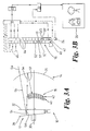
- FIGS 3A and 3B show a real time mm wave meanderline 1 ⁇ 4 ⁇ plate based conical scanning radiometer 10.
- the real time passive scanning mm wave imaging radiometer 10 has a scanner 12, a focussing lens assembly 14, an antenna feed array 16, an amplifier 18, a detector 20, a microprocessor 22, a temperature sensor 24, and an image display 26.
- the scanner 12 comprises a flat or slightly curved reflector plate 28 rotatably mounted about an axis 30, and inclined at an angle ⁇ (say about 5°) to the normal to the axis 30.
- the focussing lens arrangement 14 comprises a quarter wave meanderline plate 32 provided between a focussing dish 36 and the reflector plate 28.
- the dish 36 comprises a polarising reflector element (e.g. a wire grid).
- Incident radiation 5a is linearly polarised by the grid/dish 36, which may have wires inclined at 45° to the vertical (say) so that the component of radiation with a plane of polarisation 45° to the vertical (90° from the line of the wires in the grid) is transmitted through the grid 36.
- This linearly polarised radiation, referenced 5b encounters the meanderline plate 32.
- the plate 32 has the fast and slow axes of the meanderlines inclined at 45° to the direction of the wires on the grid 36 (and hence to the polarisation of the radiation 5b).
- Radiation 5c, emerging from the meanderline plate 32 is circularly polarised and is reflected from reflector plate 28 as radiation 5d, which is circularly polarised in the opposite sense to radiation 5c.
- An inclination of the plate 28 by ⁇ causes the scanning of an angle of 4 ⁇ over the antenna.
- the feed array antenna 16 has two rows, rows 40 and 42, of detector elements, or horns 44 (best shown in Figure 3B ). Each horn comprises a detection channel.
- a single detector element 44 has traced out on it a circular scan pattern from the observed scene as the plate 28 rotates. As the detector elements of a row lie adjacent each other the image formed from each row is a series of displaced circles, as shown in Figure 5A .
- each horn 44 (referenced 46) is fed to the amplifier 18.
- the amplifier 18 outputs to the detector 20 (e.g. a Schottky detector).
- the microprocessor 22 receives signals from the detector 20 and the temperature sensor 24 and processes these signals to produce an image 48 which is displayed on the display 26.
- the detector array may comprise a feed horn, microwave waveguide, which may have a polarisation direction, and monolithic microwave circuit (MMIC) receiver and detection circuit.
- MMIC monolithic microwave circuit
- the resolution of the radiometer is preferably diffraction - limited.
- Figures 3C to 3F illustrate that the idea of having more offset feed elements of an array, so as to decrease their effective spacing when viewed along the direction of radiation incident upon the detector array, applies not only to straight, flat, arrays, but also to curved arrays. There can be more than two lines, or tiers, of feed elements.
- Figure 3F shows a circular array modified to use the present invention (i.e. two circles, with offset feed elements). Offsetting feed elements, at different distances from the aperture of the device, allows more space for each feed element/allows a closer effective spacing.
- Figure 5A shows several detection paths 50 to 54 traced out on a scene being observed by the detector 20 (or more accurately shows the regions of a scene being observed that are detected by the detector due to the scanning motion of the plate 28).
- Circle 50 is the annular area of the scene projected onto or into a first channel (say channel 50' shown in Figure 3 ).
- Circle 51 is the annular region of the scene detected by channel 51' as the scanner scans, circle 52 that is that detected by channel 52', and so on. If the paths 50 to 54 are close enough to each other a good image of the scene can be built up. It will be appreciated that by correlating the time of the detected signal with the position of the scanner each circle 50 to 54 is actually made of discrete measurements. This represented in Figure 5B by what can be considered to be pixels 56,57,58.
- Figure 5B also shows crossover points 60 to 65 where two circles intersect. Different circles are detected by different channels. At a crossover point two channels are detecting from the same point in space in the scene.
- the adjacent (or not necessarily adjacent) channels detect from the same crossover point virtually simultaneously, or at least close enough in time for the temperature of the device not to have changed significantly, and close enough for the emitted radiation from that point in the scene not to have changed significantly (let us assume).
- V Detector Gain Channel 1 temp of device ⁇ x T Channel 1 of scene + V offset Channel 1 temp of device with the gain and offset being device-temperature dependent.
- V Detector gain ⁇ x T scene + V offset has a non-temperature related value for gain and for V offset .
- V Detection is known and so T scene can be evaluated. This is done for one of the channels, say channel 1, which serves as a main reference channel against which relative gain and offset of different channels is determined.
- channel 1 serves as a main reference channel against which relative gain and offset of different channels is determined.
- values for g 3 , V 03 can be established, either by relative comparison between channel 1 and channel 3, or channel 2 and channel 3 (channel " already having been relative-calibrated relative to channel 1" vs new uncalibrated channel).
- channel 4 crosses channel 1 (and channels 2, 3, 5, etc), and its gain and offset can be relatively calibrated.
- the system can evaluate two temperatures for it using the two crossing channels (and using their factory set absolute calibration). It is possible to take the average of what the channels say is the scene temperature and use that as the T s in the processing.
- the temperature of the focal plane array antenna 16 is important in image quality, or more precisely that variations in temperature across the focal plane array antenna are the cause of image degradation and compensation/calibration for such temperature variations can improve image quality.
- the relative calibration of the channels may take place periodically, say every second or so, or every ten seconds or so, with the device capturing images ever 40ms or so, or alternatively the relative calibration algorithm could run more often, possibly in the construction of each image, or between every 1, 2, 3, 4, 5, 10, 20, 30, 40, or more images.
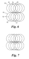
- Figure 6 shows a conical scanning pattern over a larger angle.
- the scanner may scan cones 60, 61, 62, 63, 64, 65, 66 etc in turn. Alternatively, it could scan 60, 62, 61, 63, 64, 66, 65, 67 in turn, or any pattern where adjacent conical scans are scanned close enough together in time for the scene to be taken as not to have changed significantly.
- Figure 7 shows a conical scan pattern where the lower row of scan cones intersect the upper row, with each circle/cone of the lower row intersecting a circle/cone of the upper row at two crossover points. This allows relative calibration between the circles of the upper row and those of the lower row (as described earlier), and this enhances image quality.
- the image sampling/density of scan lines in the middle of the field of view is higher than at the edges.
- the imaging sampling is more than Nyquist at the top and bottom of the image (in both directions). In the centre of the image the sampling is close to Nyquist (or just under) in the horizontal direction and Nyquist in the vertical direction (defined by temporal sampling).
- a system may be able to over-sample and get more equations than there are unknown parameters, and the equations may not solve exactly (the parameters may not work out quite the same depending upon which groups of equations are solved to determine them).
- the parameters e.g. gain and offset for a particular channel
- something e.g. averaged, or least squares fitted.
- An over-determined problem because of the scanning) can be used to advantage. It is possible to have more cross-checks to ensure solutions broadly match and are therefore reliable (and if one equation produces an anomalous result it could be omitted from the analysis. It can also be useful to have redundancy if one (or possibly more) of the channels fail.
- the conical scanning architecture of the real time imager described lends itself admirably to techniques which can improve the relative calibration. This is because many regions in the image are measured several times by different radiometer channels. The assumption that the temperature in the image does not change between measurements is generally valid, and if not, the fact can be known from examination of the raw uncalibrated data from the radiometers (and the device knows not to use that technique at that moment - indeed the device may have this check as part of its relative calibration operation). This technique can also be implemented on alternative imager architectures such as the pattern from a circular array of feeds.
- a particular channel a master channel
- the neighbouring channel would then have its gain and offset modified so that the temperature measured at the points where the channels cross are the same.
- neighbouring channels there are two cross-over points and if the scene temperatures at these two points are different (which is generally the case) the corrected gain and offset for the channel can be calculated.
- the temperatures at the two points are very similar (a fact which can be established by examining the uncorrected calibrated data) it should be arranged for the image to view a scene in which the radiation temperature across the scene varies by a large mount. For an outdoor operation, such a direction would be that towards the horizon (sky and land have different temperatures). In such a fashion this calibration method would move from one channel to the next making the relative calibration such a technique greatly improves image quality.
- Typical frequencies for radiation detected by the radiometer may be 35GHz, 94GHz, 140GHz, 220GHz; these are the atmospheric window bands for mm waves.
- the radiometer uses monolithic microwave integrated circuits (MIMICs) and has a small volume.
- MIMICs monolithic microwave integrated circuits
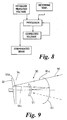
- Figure 4 shows a staring antenna 70 having a grid of antenna horns 72, a temperature detector 74 detecting the temperature of the array, an amplifier 76, and a detector 78.
- Figure 4 shows a staring array it still performs a scan for calibration purposes.
- a microscan could be performed periodically to cause more than one channel to see substantially the same point in the scene at substantially the same time (but not quite the same time).
- An optical component, or a whole imager is caused in the microscan calibration operation to move slightly (e.g. so that one channel measures the vertical and/or horizontal nearest neighbour pixels, as well as its own pixel). This "dither" creates the same multiple channels looking at the same temperature (same point at very close times) effect and so the staring array can perform relative calibration between channels. It can, of course, have absolute calibration performed on it.
- crossover points in different scans from different channels to perform a relative calibration between channels assists calibrating one channel relative to another, but it does not assist in setting the absolute calibration of the "master" channel (or indeed absolute calibration of any channel).
- the device 10 may return to a laboratory or factory periodically (e.g. every three or four months) for resetting of the absolute calibration of the channels.
- the device may be capable of adjusting its absolute calibration in the field.
- the device 10 is tested in a factory or laboratory prior to release to a customer with the device at a large number of temperatures and a performance look-up table or algorithm is constructed correlating device temperature with gain and offset voltage. Thus, for each device temperature a corresponding value for gain and offset voltage is established by the device in use. This is typically a look-up table or algorithm in the processor 22.
- This technique of correcting the device gain and offset for device temperature can be applied to devices which have relative channel to channel calibration, and to those that do not.
- the main temperature sensitive components are the rf amplifier (with perhaps about 3 ⁇ 4 of the temperature dependent effect from that) and the detector (with perhaps 1 ⁇ 4 of the temperature dependent effect from that).
- the amplifier and the detector In practice it is possible for the amplifier and the detector to be close together so that only one temperature sensor is needed.
- FIG. 3 shows only one temperature sensor 24, but the amplifier and/or detector could have either a single temperature sensor or their own temperature sensor(s). Groups of horns, or each horn, could possibly have an associated temperature detector.
- the microprocessor 22 would then receive a plurality of temperature signals from a plurality of regions/parts of the device.
- the microprocessor 22 could have a matrix/look-up table relating the temperature sensor temperature to a gain and offset, or relating different and all combinations of sensor temperatures to an associated overall device gain and offset for each channel. This would, of course, need to be established in advance of use of the device by operating the device at these combinations of temperatures to observe known scene temperatures (at least 2) and working out the appropriate gain and offset to load into the look-up table (or to create an appropriate algorithm).
- An alternative approach is to determine the effect or gain and offset of changes in temperature of one or more individual components of the device (or groups of components) and to generate the overall gain and offset from those. For example each channel (or a group of adjacent channels) may be tested in the factory to determine how their output signal (S channel ) varies with temperature of the channel (T c ) and a function S c (T c ) created (either look-up or algorithm-based).
- How the amplifier performance (S A ) varies with amplifier temperature (T A ) can be determined to create a function S A (T A ).
- the detector could be evaluated at different detector temperatures to determine how the detector voltage (V D ) varies as a function of temperature of the detector (T D ) to created V D (T D ).
- the f (T C ), f (T A ) and f (T D ) are evaluated /created by operating the device at a range of temperatures for the parameters T C , T A , T D , using reference temperature sources. It may be possible to predict one or more of f (T C ), f (T A ) or f (T D ) without physically testing the apparatus to create/determine them.
- the embodiment of Figure 1 may have several temperature sensors, so may the embodiment of Figure 4 (again, possibly a temperature sensor for the amplifier and/or detector, and one for each channel, or each group of channels).
- a further feature of the embodiment of Figure 3 is the design of its antenna.
- a conventional antenna has a single row of horns and is a certain length (in order to get the desired size of scene image scanned).
- the current spacing of horns/channels in a single row of horns is not sufficient to achieve Nyquist sampling in the image plane, thereby introducing the possibility of aliasing in the constructed image: the channels are namely are too far apart. Yet they have to be a certain size to capture the radiation of desired wavelength.
- the solution to this problem is to have a second (or further) row of horns/channels in substantially the same plane as the first row, but with the horns of the second row offset or staggered in the elongate direction of the row.
- This then essentially means that the spacing of the horns in the elongate direction is halved (for two rows).
- the centre of horns 50' and 51' are a distance D apart, but the distance apart in the elongate direction of the antenna between horn 50 of row 40 and horn 53' of row 42 is D/2. This enables us to get the horns closer together, effectively, and allows us to approach a Nyquist sampling distance, thereby avoiding aliasing in the constructed image.
- We may use three, four, or more rows of channels/horns to reduce their effective separation in the direction transverse to the scanning direction (the scanner 14 scans the observed scene over the antenna 16 in a direction perpendicular to the elongate direction of the antenna).
- the offset of the detector channels does not have to be half period, but that achieves the best resolution when there are only two rows. For three rows the offset could be 1/3 period (1/n period for n rows).
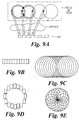
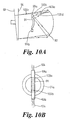
- FIG. 9 shows another real time imaging scanning radiometer 90 in a quarter wave plate, e.g. meanderline, scanner.
- the radiometer 90 has a focal plane detector array 91, a polarisation-sensitive selectively transmissive or reflective grid or dish 92, referred to as a focusing reflector (this could be a grid of parallel wires), an angled, or tilted, rotating reflector plate or disc 93, and a quarter wave plate 94.
- a meanderline plate is a known device which is essentially a quarter wave plate and which has a series of meandering lines with repeating components in orthogonal directions which have the effect, dependant upon the plane of polarisation of incident radiation and the orientation of the meanderline plate relative to it, changing the polarisation from linear to circular as it passes through the meanderline plate 94.
- the quarter wave plate 94 is for normal imaging operation arranged with its fast axis at 45° to the plane of polarisation of the radiation that reaches it from the gird 92 (45° to the plane of polarisation of the radiation 96a shown in Figure 9 ).
- the quarter wave plate 94 and the spinning disk 93 act together as a twist reflector, enabling element 92 to focus incoming radiation 96 whilst providing a conical scan of the image.
- thermal radiation 96 from an observed scene enters the radiometer and passes through the grid of parallel wires that make up the reflector 92 if the radiation is polarised with its electric field vector perpendicular to the direction of the wires. Similarly, radiation which is polarised with its electric field vector parallel direction of the wires is reflected.
- the polarised component of the incoming radiation 96 is 96a.
- the linearly polarised radiation 96a passes through the quarter waveplate 94 and is transformed to the right hand circular polarisation (RHC) radiation 96b.
- RHC right hand circular polarisation
- the RHC radiation then reflects off the plate 93 and becomes left hand circular polarisation radiation (LHC) and, passes back through the quarter wave plate 94 and is converted from LHC radiation to linearly polarised radiation 96c, but with its plane of polarisation at 90° to that of radiation 96a.
- radiation 96c is now orthogonally polarised relative to radiation 96a, and to the dish 92.
- the radiation 96c then reflects off curved reflector dish 92 (since its plane of polarisation is now at 90° to what it was when it came in originally) and is focused onto the focal plane detector array 91. This is the normal imaging operation. It will be recalled that the receiver feed horns of the array 91 have a polarisation plane, which shall be assumed to be parallel to that of the radiation receiving it, after the optics discussed above.
- the focal plane array 91 could be a linear, or curved, or an annular array of detector feed elements/radiometer receivers.
- Figure 9b shows a linear array of receiver feed elements, or channels, in an image plane.
- Figure 9c shows that the array of Figure 9b gives linearly displaced circles of sensitivity in the imager field of view.
- Figure 9d shows an annular array of receiver feed elements, or channels in the focal plane, which gives rise to an annularly displaced set of circles of sensitivity in the imager field of view, shown in Figure 9e .
- the centres of the circles of sensitivity of the imager field of view shown in Figures 9c and 9e are placed either in a line or circle, depending if they are associated with the linear array of Figure 9b or the annular array of Figure 9c .
- the radiometer also has a defocused mode. If the dish reflector 92 is rotated by 90° in comparison with its orientation in the discussion above then the radiation entering the detector array 91 is unfocused, and so will be substantially the same for all channels in the detector horn array 91. This is because in this configuration the polarisation to which the detector horn array is sensitive radiation can pass directly through the grid 92 without passing through any of the scanning optics (components 94 and 93) and hence without being focussed.
- a thermal radiation source 99a, a hot source, and another radiation thermal source 99b, a cold source are placed diametrically opposite each other at the periphery of the detector array 91. These sources can be used for the purposes of calibration. As will be described later, rotation of quarter waveplate 94 by 45° (from the normal imaging mode) causes radiation from these sources to enter the channels of the array 91. The fast (or slow) axis of the quarter waveplate is now parallel to the direction of the wires in grid 92. In this calibration configuration, as the disk 93 rotates an annular image of the detector array 91 is traced out in the focal plane. This means each detector channel gets to measure alternately the emission from the hot and cold calibration sources.
- radiation 100a is emitted by a source 99a or 99b.
- Linearly polarised radiation 100b is reflected back from dish 92 (and orthogonally polarised radiation passes through the dish), the radiation 100b has its plane of polarisation parallel to one of the fast or slow axes of the quarter wave plate meanderline 94 and passes through it, still linearly polarised, is reflected from rotating disc 93 as radiation 100c, (still linearly polarised), passes back through the meanderline plate 94, re-encounters the dish 92, and is reflected and focussed by the dish 92 (radiation 100d) to a point 102 at the periphery of the array 91.
- the radiation 100a reflected from the dish 92 is a nearly parallel beam (because the source 99a or 99b is nearly at the focal point of the dish 92), and that the thermal emissions from quite a large angular range are collected by the dish 92, as the disk 93 rotates.
- the effect of arrangement of Figure 10a is that the outermost two (or perhaps more) channels 103a and 103b of the array see a known temperature, the thermal source temperature, and that this can be used for absolute calibration of those channels, which may be used as a reference channel, or channels, for the relative calibration of other channels.
- the relevant factor in operating the radiometer in a defocused mode is the relative orientation of the wires in the grid polariser 92 with respect to the plane of polarisation to which the array detectors are sensitive. Rotating the grid polariser 92 by 90° (from its normal mode of imager mode of operation) changes the system from one that focuses to one that receives unfocussed radiation.
- the rotation of the tilted disc 93 causes the point adjacent the focal plane array that is focused onto the array 91 to trace out the annulus 91a of varying diameters in the focal plane.
- the thermal source 98 may initially be a hot or a cold load placed adjacent to the array 91, and in a second calibration operation it is the other of the hot or cold loads.
- a single thermal source may be provided, possibly of changeable temperatures, or two different temperature sources, as shown in Figures 10a and b.
- the thermal load could be a true thermal load, emission of thermal radiation being from thermal absorbers at the two different temperatures.
- the temperature of the thermal source 99a or 99b could be liquid nitrogen temperature, or another defined temperature. They could range to a few hundred Kelvin. It is best if the temperature of the source 98 is known. There may be a temperature sensor e.g. thermistor to measure the temperature of the thermal source 99a or 99b, or it may be known in some other way (e.g. the boiling point of liquid nitrogen at atmospheric pressure is known).
- the thermal source may be manually mountable and/or demountable, or it may comprise a receptacle provided adjacent the focal plane array capable of holding a source of hot or cold loads.
- thermoelectric e.g. solid state sources, such as Peltier effect devices.
- the radiometer 90 system could have an absolute calibration with a single source 99 of known temperature, or with two known (but different) source temperatures, periodically, say daily, weekly, monthly. The system could then perform relative calibration much more frequently (e.g. of the order of every few seconds, or as discussed earlier).
- the source 99 or sources 99 are in the embodiment of Figure 9 presented to each channel in the system.
- the scanner configuration shown in Figures 9 and 10 has low optics losses, in the example about 0.5dB. This compares well with the losses of the scanner in UK Patent Application No. 9707654.1 which has losses of around 4dB. Thus, the system of Figures 9 and 10 is at least twice as sensitive as that of GB 9707654.1 .
- the channels of the detector array need electronic communication to the processor or controller that processes their signals, and that this is provided by electric cables 104 which extend out along a diameter of the device.
- the cables obscure part of the radiation incident upon the device.
- the addition of the hot and cold sources 99a and 99b on the same line as the exit areas of the array's cables does not obscure substantially any more of the operational area of the imager than is already obscured by the cables 104.
- introducing the source 99 does not significantly reduce the optical performance of the device.
- the desired radiation bandwidth is not restricted by the ferrite as in the scanner of GB 9707654.1 , which is a ferrite-based scanner.
- this system could be used at the 94GHz window. It could also be used at the higher frequencies of 140GHz, 220GHz and beyond where it may be difficult to find a suitable ferrite. It has a much more flexible operational range of frequencies.
- the angular movement of the reflector 92 and/or the meanderline plate 94 could be effected manually, or the radiometer may have motors to achieve this, under control of a controller.
- the user may be able to initiate a calibration operation by inputting a command.
- Figure 11 shows another conical imaging scanner 110 having a Cassegrain configuration.
- a primary reflector 112 reflects and focuses radiation onto a subreflector 114 which reflects and assists in focussing the radiation into a horn 116, or a focal plan horn array (similar to that shown in Figure 3 ).
- the apparatus is inherently linearly polarised because of the rectangular horn and waveguide.
- a linear polariser in the path of the radiation - for example in front of the horn 116, or in front of the whole imaging scanner (possibly as part of the scanner).
- the linear polariser could be half-wave plate. If it is placed before the horn it can be physically small, whereas if it is before the radiation reaches the primary reflector 112 it needs to be bigger.
- Figure 12 shows a half-wave plate 118. This routes the plane of polarisation of incoming linearly polarised radiation 119 through an angle that is twice the angle between the rectangular horn E direction and the optical axis of half-wave plate. Thus, if ⁇ is 45° the half-wave plate 118 rotates the plane of polarisation by 90°.
- Figure 12 shows horn 116 having a vertical polarisation and incoming horizontally polarised radiation 119.
- the plate 118 can effectively switch off external radiation entering the wave-guide associated with the horn (because the horn has a place of polarisation and the plate 118 can be orthogonally crossed).
- angular displacement of the plate can cause the focussing effect of the focussing dish 119 to be lost, effectively defocusing the device.
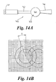
- Figure 14a shows an arrangement for absolute calibration in which a radiometer 140 has a detector 141, a cavity 142, a switch 143, and an antenna 144.
- the radiometer also has a calibration configuration or mode in which the switch 143 is closed and the radiation that enters the radiometer body is that from the cavity.
- the temperature of the cavity can be measured (the machine has a temperature sensor 145) a known thermal temperature profile of radiation will be incident upon the detector.
- the architecture of this system may at first glance appear similar to that of the Dicke radiometer which was a switch to compensate for changes in noise temperature, but the present system has a slower switch to calibrate for variation in radiometer device temperature (not noise temperature), to correct the gain and/or offset voltage.
- the cavity 142 could be a length of low loss waveguide.
- the switch 143 can be a pin diode.
- the radiometer may have part of its temperature stabilised by insulation and/or a heating/cooling system.
- the front end (antenna 144, switch 143, and waveguide cavity 142) may be temperature-stabilised.
- Such alternative source signals could include known magnitude signals (e.g. from an RF source).
- Alternative source signals at two different levels would usually be provided at different times, to enable both gain and offset to be evaluated.
- a single level could be used if the gain and offset can be limited to a single parameter, e.g. temperature.
- Heating/cooling temperature control equipment e.g. Peltier effect thermoelectric devices
- Peltier effect thermoelectric devices can be used to maintain the temperature of some or several or all temperature sensitive components of the imager.
- the design of the imager can be such as to have temperature sensitive components associated with thermal reservoirs of high thermal mass so that their temperature does not change rapidly.
- the detector or detector array can be mounted on a large metal block.
- a scanning imager rather than a staring array because a staring array is more expensive. If the cost difference reduces, or is worth paying, a staring array may be preferred. With a staring array there is the advantage that one can look at pixels for longer and this makes the noise smaller, and that can be advantageous. However, there are some disadvantages to staring arrays and these are that one cannot get Nyquist sampling unless microscan is performed, sampling in-between the pixels. Furthermore, once you start scanning then you can also get relative calibration. So in actual fact scanning is not so bad, and in spite of the fact the noise is more as you are not looking at each pixel for very long it is good enough for many applications.
- a system with a set of gain an offset coefficients for each point in the scan is envisaged. Again these could be established by testing the device in-factory.
- a further technique applicable to the embodiments previously described and also to other devices, is that of de-focussing the observed scene so as to homogenise the signal received by each channel.
- De-focussing the radiation received by channels also has a purpose in relative calibration. As part of the relative calibration technique discussed a comparison of two channels at their crossover points has been discussed because the channels see the same temperature at that point. De-focussing also means that each channel sees substantially the same temperature. Thus de-focussing the channels and then establishing the relative calibration between channels has advantages. It also allows for relative calibration of systems which do not have crossover points (e.g. staring arrays). De-focussing to achieve the same scene temperature for each channel for relative calibration may be performed instead of, or as well as, crossover point comparison.
- the image is, of course, re-focussed for the image data collection process.
- the grid 36 could be rotated to achieve de-focus. This may be more difficult mechanically, but still achievable. Both grid 32 and grid 36 could be rotated to achieve the same effect (e.g. 45° each). There needs to be a change in the relative orientation of polarisation of the grid 32 and the grid 36, substantially 90° being best.
- the defocusing technique will work on a ferrite conical scanner and a meanderline conical scanner by rotating the polarising grid facing the receiver feed horns. It could also be achieved by a polarisation switch in the horn feed by flipping the received polarisation by 90°.
- the radiation temperature over the whole of the bland scene is the same. This may be in security imaging applications where things are very close to the imager. In this case it is possible to make the assumption that adjacent channels are measuring the same temperature. Thus, in the discussion which says that two channels may observe the same point in the scene it is also intended to cover observing nearly the same point close enough so that it is reasonable to assume that the channels are observing the same temperature, or nearly so.
- Redundancy in detection channels that contribute to an image can be very helpful.
- Round-up errors can be minimised by averaging values, and it also allows the system to compensate for failed detectors (e.g. by using signals from working detectors). It also allows for the comparison of the evaluated temperature, as evaluated by more than one channel, so as to identify significantly different estimated temperatures and hence identify potentially failed detectors and/or channels.
- polarisation sensitive defocusing can also be achieved by the use of a polarisation switch. If a polarisation switch is provided directly in front of the detector the radiation being detected would be unfocused.
- the polariser could be a meanderline arrangement, or a ferrite in fundamental waveguide in the feed. Figure 12 illustrates this idea.
- a further feature which may be provided is the ability to use a change in polarisation (or other switch mechanism) to switch the signals incident upon the focal plane receiver feed array from being signals from the observed scene to being from a reference calibration scene.
- the meanderline plate rotation discussed in relation to Figure 10 is an example of this.
- Another technique which may be employed is a single point relative calibration. This is applicable to absolute calibration and to relative calibration techniques. Traditionally, it is necessary to calibrate two channels for gain and offset by looking at two temperature sources at two different, and known, temperatures. If the temperature of the device is known or is estimated there is effectively one only unknown in the calibration equation instead of two. This means that given an absolute calibration (in-factory) relative calibrations between channels can be performed using emissions from a single source of known temperature.
- single point calibration it is desired to obtain a relative calibration when one can only present to the channels a single temperature. If one only has a single temperature then one only has two equations for four unknowns.
- the single point calibration makes use of the assumption that says the two unknowns, the gain and offset, are not truly independent. There is in fact a link. Once this is assumed there is only really one unknown for a single channel. The assumption is to say that the thing that links the gain and the offset is the temperature of the system. This is an assumption of course, but a reasonable one. This is because most changes in gain and offset are due to temperature changes. This means one needs to measure the temperature of the system. Then the temperature, the link between the gain and the offset, is known and it is possible to look up the gain and offset relation, and then there is one unknown. So for the single temperature one has two equations and two unknowns.
- This single point relative calibration technique can be used with or without the de-focussing technique discussed earlier.
- the single point calibration technique could be used with the sky, for example, as the single source (or the ground).
- the device may have a dedicated channel directed at the single source. This may avoid having to point the entire device at the reference source.
- Figure 4 shows a dedicated horn 79 directed at the sky. Not having to point the detector array at the reference calibration source means that it is possible to calibrate frequently, for example for each image, or periodically every few, or tens, of images.
- Figure 14 shows schematically a scene 140 that has been notionally pixellated into pixels 142.
- Annular scan pattern 144 is the part of the observed scene that is projected, portion by portion over time, onto a single channel feed in the radiometer of Figure 9 as the inclined disc 93 rotates.
- Annular scan pattern 146 is the part of the observed scene that is projected in serial sequence onto a second channel feed in the radiometer of Figure 9 (and as shown in Figure 9a ).
- Each pixel in the scan path 142 may have a different gain and offset associated with them, for the same channel, due to geometric effects of the instrument.
- Figures 15a and 15b show this. Indeed, there may be two significant "blips" in the gain and offset profiles with angle around the scan ( ⁇ ), about 180° apart. These may be associated with the base plate which hold the detectors and electrical wires 104 leading to the detector array, which are at 180° diametrically opposed positions.
- scan angle ⁇ may have its own associated gain and offset for each channel. These may be factory set (and indeed will usually initially be factory-set). However, as discussed earlier, gain and offset are dependant upon the temperature of the instrument. The gain and offset for each scan angle will also be temperature dependent to some degree.
- V T g ⁇ T + V O ⁇ T
- T is the temperature of the radiometer (or at least the temperature of a critical temperature-dependant component).
- Absolute calibration of the gain and/or offset of a channel at scan angle ⁇ may be provided.
- a plurality of absolute calibration of the gains and/or offsets of a channel at different scan angles ⁇ may be provided.
- Preferably absolute calibration at substantially all values of ⁇ is provided.
- detecting and compensating for variations in gain and offset of a channel with ⁇ can be achieved by time gating the detected signals so that a "window" opens electronically when the scan angle is at a particular ⁇ , so that the detector essentially only sees scene information at that angle ⁇ . Moving the timing of the gating, relative to the top point of the scan changes the scan angle ⁇ being observed.
- One solution is to determine the variation of gain and offset with scan angle in the factory/laboratory for each channel and to modify the factory settings with relative gain and relative offset values determined in situo, in use of the radiometer, with the relative gain and relative offset compensating for inter-channel variations with temperature being scan angle independent - i.e. the same relative channel compensation for temperature variation irrespective of scan angle, but sensitive to the temperature of the instrument.
- a further possibility is to have a set of scan angle dependant modifications for gain and offset for each channel, each modification for each channel being temperature dependent and known.
- free standing calibration, and/or absolute calibration and/or relative calibration could be employed, in any combination, and possibly all three.
- Free standing calibration may be used before relative calibration.
- the frequency of relative calibration of the channels may be the same as, or more than, or less than, that of free standing calibration of the channels.
- angle ⁇ controls how large is the scan pattern of the imager (for a tilt angle ⁇ the full width of the scanning cone angle is 4 ⁇ ).
- the tilt angle ⁇ could be reduced, thus reducing the conical scan angle. This would increase the amount of data collected along a central line in the image and raise the signal noise ratio in this part of the image.
- the internal surfaces of the radiometer could be coated with an energy absorbing coating (absorbing at least in the wavelengths being use for imaging/detection in the radiometer). This prevents spurious radiation spoiling the relationship between incident scene radiation and radiation detected by the detector array. It also helps to reduce the variation of gain and offset with respect to scan angle.
- the radiometer operates at 25HZ (i.e. 25 "constructed" frames per second of the scene, built from conical scan paths which substantially fill the region of the scene being observed).
- the integration time for certain selected pixels of the observed scene could be increased, for example from say a few tens of microseconds to seconds.
- the area of the observed scene that is looked at for longer could be determined by the human operator, or alternatively by software (e.g. pattern recognition software could identify a known object, or a suspected object, and the control processor could increase the integration time of the pixels in the area of the object).
- the degree of increase in pixel integration may be user, or computer, controlled, for example over a range of tens of microseconds to seconds.
Landscapes
- Physics & Mathematics (AREA)
- General Physics & Mathematics (AREA)
- Electromagnetism (AREA)
- Radiation Pyrometers (AREA)
- Measuring Temperature Or Quantity Of Heat (AREA)
- Indication And Recording Devices For Special Purposes And Tariff Metering Devices (AREA)
Claims (14)
- Verfahren zur Verbesserung der Bildqualität eines bildgebenden Mehrkanal-Radiometers (10), das mindestens einen ersten Kanal, der Strahlung unter Verwendung eines ersten Detektors (50') erfasst, und einen zweiten Kanal aufweist, der Strahlung unter Verwendung eines zweiten Detektors (51') erfasst,
wobei das Verfahren das Ändern der Verstärkung und/oder des Offsets, die in den Gleichungen der Beziehung zwischen Szenetemperatur und Detektorspannung verwendet werden, für den ersten und den zweiten Kanal umfasst, wobei Werte für die Verstärkung und den Offset verwendet werden, die durch Durchführen einer Kanal-Eichungsoperation abgeleitet wurden, und wobei die Kanal-Eichungsoperation umfasst:Abtasten einer ersten Abtastspur (50) von einer beobachteten Szene auf den ersten Kanal und Abtasten einer zweiten Abtastspur (51) von der beobachteten Szene auf den zweiten Kanal und Schneiden der Abtastspuren an mindestens zwei voneinander beabstandeten Punkten (60, 63) in der beobachteten Szene, um zu gewährleisten, dass der erste und der zweite Kanal einen ersten Teil der Szene zu einem ersten Zeitpunkt und einen zweiten Teil der Szene zu einem zweiten Zeitpunkt beobachten,undVerwenden der Ausgänge vom ersten und vom zweiten Detektor zum ersten Zeitpunkt und zum zweiten Zeitpunkt bei der Eichoperation, um einen geänderten Wert für die Verstärkung und/oder den Offset für den ersten und/oder den zweiten Kanal zu erzeugen,wobei das Radiometer die geänderte Verstärkung und oder den geänderten Offset für den ersten und/oder den zweiten Kanal verwendet, um unter Verwendung des ersten und des zweiten Kanals ein Bild zu erzeugen. - Verfahren nach Anspruch 1, bei dem bei einem dritten Kanal, oder bei weiteren Kanälen, die Verstärkung und der Offset in Bezug auf den ersten oder den zweiten Kanal unter Anwendung einer Kanal-Eichungsoperation geeicht werden, bei der zwei Kanäle mindestens zwei unterschiedliche, voneinander beabstandete Teile der Szene (61, 64) beobachten und die Detektorsignale von ihnen zur Eichung der Verstärkung und des Offsets eines Kanals in Bezug auf den anderen Kanal verwendet werden.
- Verfahren nach einem der vorhergehenden Ansprüche, bei dem relativ zu einem Kanal als Referenzkanal die Verstärkung und/oder der Offset des anderen Kanals/der anderen Kanäle festgelegt wird/werden.
- Verfahren nach einem der vorhergehenden Ansprüche, bei dem bei der relativen Eichungsoperation sowohl die Verstärkung als auch der Offset eines Kanals geändert werden.
- Verfahren nach einem der vorhergehenden Ansprüche, bei dem bei der relativen Eichungsoperation die Verstärkung und/oder der Offset von Kanal 1 und von Kanal 2 unter Anwendung der folgenden Gleichungen ermittelt wird:


um einen oder mehrere oder sämtliche der folgenden Werte zu ermitteln: Verstärkung von Kanal 1, Verstärkung von Kanal 2, Offset von Kanal 1 und Offset von Kanal 2. - Verfahren nach Anspruch 5, bei dem die Gewinnung von Werten zur Verwendung in den Gleichungen (i) und (ii) für eine zum ersten Zeitpunkt beobachtete Temperatur 1 und eine zum zweiten Zeitpunkt beobachtete Temperatur 2 wiederholt wird, was folgende vier Gleichungen ergibt:


und das Verfahren das Lösen der Gleichungen umfasst, um die vier unbekannten Variablen g1, V01, g2, V02 mit Tbeobachtet A und Tbeobachtet B und den bekannten Detektorspannungen zu ermitteln. - Verfahren nach einem der vorhergehenden Ansprüche, das die Überprüfung der Werte vor der Änderung für die Temperatur umfasst, die vom ersten und vom zweiten Kanal beobachtet wird, um sicherzustellen, dass sie nahe genug beieinander liegen, um sie als zwei Kanäle betrachten zu können, welche die gleiche Temperatur messen.
- Verfahren nach einem der vorhergehenden Ansprüche, das ferner einen Schritt umfasst, bei dem bewirkt wird, dass die beiden Kanäle im Wesentlichen die gleiche Temperatur sehen, durch (i) Defokussieren des Radiometers oder (ii) Umschalten der auf die Detektoren einfallenden Strahlung von Szenestrahlung auf Referenzstrahlung.
- Verfahren nach Anspruch 8, bei dem Referenzstrahlung durch eine thermische Quelle geliefert wird, die Temperatur der thermischen Quelle gemessen wird und die Temperatur der thermischen Quelle verwendet wird, um die Verstärkung und den Offset für die Kanäle zu ermitteln.
- Bildgebendes Mehrkanal-Radiometer (10),
das aufweist:einen ersten Kanal mit einem Detektor (50') für den ersten Kanal, der so ausgebildet ist, dass er mit einer Aufnahmeeinrichtung für beobachtete Szenestrahlung des ersten Kanals verbunden werden kann, und einen zweiten Kanal mit einem Detektor (51') für den zweiten Kanal, der so ausgebildet ist, dass er mit einer Aufnahmeeinrichtung für beobachtete Szenestrahlung des zweiten Kanals verbunden werden kann, sowie einen Signalprozessor (22),und in dem Strahlungssignale der beobachteten Szene durch den ersten und zweiten Kanal zum ersten beziehungsweise zum zweiten Detektor geleitet werden können und die Detektoren so ausgebildet sind, dass sie im Betrieb einen ersten und einen zweiten Detektorausgang an den Signalprozessor liefern, wobei der Signalprozessor so ausgebildet ist, dass er im Betrieb Ausgangssignale liefert, die für die in der beobachteten Szene durch den ersten und den zweiten Kanal beobachteten Temperaturen repräsentativ sind,und bei dem der Signalprozessor so ausgebildet ist, dass er im Betrieb die empfangenen Ausgänge des ersten und des zweiten Detektors unter Verwendung von Werten, die repräsentativ sind für oder beeinflusst sind durch die Verstärkung und den Spannungs-Offset oder mit der Verstärkung und dem Spannungs-Offset in Verbindung stehen, für den ersten und für den zweiten Kanal verarbeitet, um die Verstärkung und den Spannungs-Offset für den zweiten Kanal relativ zur Verstärkung und zum Spannungs-Offset des ersten Kanals zu eichen,dadurch gekennzeichnet, dassdas Radiometer eine Abtasteinrichtung (28) aufweist, die so ausgebildet ist, dass sie eine beobachtete Szene in der Weise abtastet, dass sich die Abtastspuren (50, 51) so überlappen oder schneiden, das der gleiche Punkt (60) in der beobachteten Szene durch mehr als einen Kanal gesehen wird, um zu gewährleisten, dass der erste und der zweite Kanal einen ersten Teil der Szene zu einem ersten Zeitpunkt und einen zweiten Teil der Szene zu einem zweiten Zeitpunkt beobachten,wobei der Signalprozessor so ausgebildet ist, dass er bei der Eichungsoperation die Ausgänge vom ersten und vom zweiten Detektor zum ersten Zeitpunkt und zum zweiten Zeitpunkt verwendet, um einen geänderten Wert für die Verstärkung und/oder den Offset für den ersten und/oder den zweiten Kanal zu erzeugen. - Radiometer nach Anspruch 10, bei dem der Signalprozessor so ausgebildet ist, dass er für jeden Kanal die Gleichung

oder eine äquivalente Beziehung verwendet, um die geänderte Verstärkung und den geänderten Offset zu ermitteln. - Radiometer nach Anspruch 10 oder 11, das so ausgebildet ist, dass es nach einem konischen Abtastschema arbeitet.
- Radiometer nach einem der Ansprüche 10 bis 12, das mit einer bildgebenden Fokussieranordnung und einer Defokussiereinrichtung, die das erfasste Bild defokussieren kann, ausgerüstet ist.
- Radiometer nach einem der Ansprüche 10 bis 13, das einen Umschalter für die beobachtete Strahlung aufweist, der so ausgebildet ist, dass er im Betrieb die Strahlung, die auf die Detektoren auftrifft, von Strahlung, die von der Szene herrührt, zu Strahlung umschaltet, die nicht von der Szene stammt.
Applications Claiming Priority (3)
| Application Number | Priority Date | Filing Date | Title |
|---|---|---|---|
| GBGB0104203.5A GB0104203D0 (en) | 2001-02-21 | 2001-02-21 | Calibrating radiometers |
| GB0104203 | 2001-02-21 | ||
| PCT/GB2002/000744 WO2002066945A1 (en) | 2001-02-21 | 2002-02-21 | Calibrating radiometers |
Publications (2)
| Publication Number | Publication Date |
|---|---|
| EP1362227A1 EP1362227A1 (de) | 2003-11-19 |
| EP1362227B1 true EP1362227B1 (de) | 2011-04-06 |
Family
ID=9909156
Family Applications (1)
| Application Number | Title | Priority Date | Filing Date |
|---|---|---|---|
| EP02702478A Expired - Lifetime EP1362227B1 (de) | 2001-02-21 | 2002-02-21 | Eichverfahren eines radiometers |
Country Status (6)
| Country | Link |
|---|---|
| US (1) | US6900756B2 (de) |
| EP (1) | EP1362227B1 (de) |
| JP (1) | JP3983672B2 (de) |
| DE (1) | DE60239665D1 (de) |
| GB (1) | GB0104203D0 (de) |
| WO (1) | WO2002066945A1 (de) |
Families Citing this family (38)
| Publication number | Priority date | Publication date | Assignee | Title |
|---|---|---|---|---|
| US6834991B2 (en) * | 2002-09-23 | 2004-12-28 | Raytheon Company | Radiometer with programmable noise source calibration |
| US7307492B2 (en) * | 2002-11-27 | 2007-12-11 | Intel Corporation | Design, layout and method of manufacture for a circuit that taps a differential signal |
| US6870162B1 (en) * | 2003-01-31 | 2005-03-22 | Millivision, Inc. | Weighted noise compensating method and camera used in millimeter wave imaging |
| GB0314422D0 (en) * | 2003-06-20 | 2003-07-23 | Qinetiq Ltd | Image processing system |
| US7603088B2 (en) | 2003-09-18 | 2009-10-13 | Reveal Imaging, Llc | Multi-channel radiometer imaging system and MMIC chips for use thereof |
| US7034516B2 (en) * | 2003-09-18 | 2006-04-25 | Xytrans, Inc. | Multi-channel radiometer imaging system |
| US7088086B2 (en) * | 2003-09-18 | 2006-08-08 | Xytrans, Inc. | Multi-channel radiometer imaging system |
| US7221141B2 (en) * | 2004-07-14 | 2007-05-22 | Xytrans, Inc. | Switched measuring system and method for measuring radiant signals |
| WO2006088845A2 (en) * | 2005-02-15 | 2006-08-24 | Walleye Technologies, Inc. | Electromagnetic scanning imager |
| US8253619B2 (en) | 2005-02-15 | 2012-08-28 | Techtronic Power Tools Technology Limited | Electromagnetic scanning imager |
| US8593157B2 (en) * | 2005-02-15 | 2013-11-26 | Walleye Technologies, Inc. | Electromagnetic scanning imager |
| US7402799B2 (en) * | 2005-10-28 | 2008-07-22 | Northrop Grumman Corporation | MEMS mass spectrometer |
| US20080116239A1 (en) * | 2006-11-17 | 2008-05-22 | Lu Shin-Chiang | Multifunctional Yoga Stretch Strap |
| US7588368B2 (en) * | 2006-12-20 | 2009-09-15 | Cummins Inc. | System for diagnosing temperature sensor operation in an exhaust gas aftertreatment system |
| US7724134B2 (en) * | 2007-06-15 | 2010-05-25 | Icove And Associates, Llc | Passive microwave fire and intrusion detection system |
| US8044798B2 (en) * | 2007-06-15 | 2011-10-25 | Icove And Associates, Llc | Passive microwave speed and intrusion detection system |
| US8493212B2 (en) * | 2007-06-15 | 2013-07-23 | Icore and Associates, LLC | Passive microwave system and method for protecting a structure from fire threats |
| US8049620B2 (en) * | 2007-06-15 | 2011-11-01 | Icove And Associates, Llc | Passive microwave fire and intrusion detection system including black body and spectral emission at the hydrogen, hydroxyl and hydrogen chloride lines |
| US8213672B2 (en) | 2007-08-08 | 2012-07-03 | Microsemi Corporation | Millimeter wave imaging method and system to detect concealed objects |
| JP2010008273A (ja) * | 2008-06-27 | 2010-01-14 | Maspro Denkoh Corp | ミリ波撮像装置 |
| US20110084868A1 (en) * | 2009-10-08 | 2011-04-14 | Brijot Imaging Systems, Inc. | Variable range millimeter wave method and system |
| DE102010031215B3 (de) * | 2010-07-12 | 2011-12-29 | Carl Zeiss Smt Gmbh | Verfahren sowie Anordnung zur Kalibrierung einer CCD-Kamera |
| TW201321789A (zh) | 2011-11-16 | 2013-06-01 | Ind Tech Res Inst | 成像系統與掃描方法 |
| TWI434057B (zh) * | 2011-11-24 | 2014-04-11 | Ind Tech Res Inst | 輻射計之校正裝置、校正系統與校正方法 |
| US9343815B2 (en) * | 2013-06-28 | 2016-05-17 | Associated Universities, Inc. | Randomized surface reflector |
| US10197451B2 (en) * | 2013-10-04 | 2019-02-05 | Battelle Memorial Institute | Contrast phantom for passive millimeter wave imaging systems |
| EP3109937A4 (de) * | 2014-02-17 | 2017-10-18 | Nec Corporation | Antennenvorrichtung und verfahren zur steuerung der antennenvorrichtung |
| US9641772B2 (en) | 2014-11-19 | 2017-05-02 | Northrop Grumman Systems Corporation | Compact PMMW camera calibration target |
| TWI607200B (zh) * | 2016-04-12 | 2017-12-01 | 中國鋼鐵股份有限公司 | 即時感測系統 |
| EP3526561A4 (de) | 2016-10-17 | 2020-06-03 | University of Ottawa | Vorrichtung und verfahren zur kalibrierung von messinstrumenten |
| KR101871928B1 (ko) * | 2017-03-17 | 2018-06-27 | 동국대학교 산학협력단 | 라디오미터 및 그 동작 방법과 이를 이용한 화재 감지 시스템 |
| WO2018169349A1 (ko) * | 2017-03-17 | 2018-09-20 | 동국대학교 산학협력단 | 라디오미터 및 그 동작 방법과 이를 이용한 감시 시스템 |
| KR101950592B1 (ko) * | 2017-06-26 | 2019-02-21 | 국방과학연구소 | 라디오미터의 온도 의존성 보상 방법 |
| CN107478338B (zh) * | 2017-08-07 | 2020-05-19 | 松下电器机电(中国)有限公司 | 一种提高红外线阵列传感器采样分辨率的方法及装置 |
| CN108254076B (zh) * | 2017-11-22 | 2020-11-17 | 安徽四创电子股份有限公司 | 一种用于多通道毫米波辐射计的标定方法 |
| CN111693141B (zh) * | 2020-06-24 | 2024-01-09 | 中国科学院空天信息创新研究院 | 一种太阳辐射计视场角的检测方法 |
| CN114674442B (zh) * | 2022-02-24 | 2025-04-29 | 昆山恒准技术服务有限公司 | 辐射计校准用光源系统 |
| CN114993484B (zh) * | 2022-08-02 | 2022-10-28 | 国家卫星海洋应用中心 | 一种星载微波辐射计异常数据检测方法、装置及电子设备 |
Family Cites Families (33)
| Publication number | Priority date | Publication date | Assignee | Title |
|---|---|---|---|---|
| GB1308463A (en) * | 1969-03-06 | 1973-02-21 | Coackley R Reynolds M L | Radiometer apparatus |
| US3895182A (en) * | 1973-12-20 | 1975-07-15 | Ted R Trilling | Multi-channel sensor system |
| US4121459A (en) * | 1976-03-17 | 1978-10-24 | Macall Thomas F | Temperature profile measuring devices |
| JPS6049855B2 (ja) * | 1980-12-05 | 1985-11-05 | 三菱電機株式会社 | マイクロ波放射計 |
| US4456390A (en) * | 1981-10-26 | 1984-06-26 | Wahl Instruments, Inc. | Noncontact temperature measuring device |
| US4521861A (en) * | 1982-04-30 | 1985-06-04 | Texas Instruments Incorporated | Method and apparatus for enhancing radiometric imaging |
| US4499470A (en) * | 1982-05-06 | 1985-02-12 | The United States Of America As Represented By The Administrator Of The National Aeronautics And Space Administration | Method of measuring sea surface water temperature with a satellite including wideband passive synthetic-aperture multichannel receiver |
| DE3241752C2 (de) * | 1982-11-11 | 1984-09-06 | Messerschmitt-Bölkow-Blohm GmbH, 8012 Ottobrunn | Richtungsstabilisierte Bildfeldabtastung |
| DE786649T1 (de) | 1985-04-17 | 1998-05-14 | Thermoscan Inc | Elektronisches Infrarotthermometer und Verfahren zur Temperaturmessung |
| GB8515370D0 (en) | 1985-06-18 | 1985-08-07 | Negretti Aviat Ltd | Detection for contamination of optical system of pyrometer |
| US4705945A (en) * | 1986-01-31 | 1987-11-10 | Barnes Engineering Company | Narcissus correction for infrared scanning microscope |
| GB2200813B (en) | 1987-02-03 | 1991-06-05 | Gec Avionics | Thermal imager |
| EP0411121A4 (en) | 1987-12-25 | 1991-05-15 | Nippon Steel Corporation | Optical thermometer |
| US4873481A (en) * | 1988-02-16 | 1989-10-10 | Radiometrics Corporation | Microwave radiometer and methods for sensing atmospheric moisture and temperature |
| GB2217442B (en) | 1988-04-22 | 1992-04-15 | Philips Electronic Associated | Temperature compensated thermal radiation detectors |
| DE3836294A1 (de) | 1988-10-25 | 1990-04-26 | Eltro Gmbh | Waermebildgeraet mit detektorausgleich |
| JPH0738025B2 (ja) | 1989-05-23 | 1995-04-26 | ダイキン工業株式会社 | 放射計測方法および放射計 |
| DE69011655T2 (de) | 1989-11-30 | 1995-02-16 | Texas Instruments Inc | Schaltung und Verfahren zur Normierung eines Detektorausgangs. |
| US5089204A (en) * | 1990-03-16 | 1992-02-18 | Nkk Corporation | Method of extruding thermoplastic resin pipe |
| DE4029643C1 (de) | 1990-09-19 | 1991-07-18 | Eltro Gmbh, Gesellschaft Fuer Strahlungstechnik, 6900 Heidelberg, De | |
| US6018587A (en) * | 1991-02-21 | 2000-01-25 | Applied Spectral Imaging Ltd. | Method for remote sensing analysis be decorrelation statistical analysis and hardware therefor |
| US5231404A (en) * | 1991-05-17 | 1993-07-27 | Georgia Tech Research Corporation | Dual-polarized cross-correlating radiometer and method and apparatus for calibrating same |
| US5354987A (en) * | 1992-12-07 | 1994-10-11 | Texas Instruments Incorporated | Calibrating focal plane arrays using multiple variable radiometric sources |
| NL9300312A (nl) | 1993-02-19 | 1994-09-16 | Hollandse Signaalapparaten Bv | Optische aftastinrichting. |
| US5587583A (en) * | 1995-09-06 | 1996-12-24 | Hughes Electronics | Thermal imaging device |
| US6515285B1 (en) * | 1995-10-24 | 2003-02-04 | Lockheed-Martin Ir Imaging Systems, Inc. | Method and apparatus for compensating a radiation sensor for ambient temperature variations |
| GB2323929B (en) | 1996-06-11 | 1999-06-09 | Lg Electronics Inc | Apparatus and method for measuring food temperature in microwave oven |
| JPH10122956A (ja) | 1996-10-22 | 1998-05-15 | Mitsubishi Electric Corp | 赤外線カメラ |
| US6028309A (en) * | 1997-02-11 | 2000-02-22 | Indigo Systems Corporation | Methods and circuitry for correcting temperature-induced errors in microbolometer focal plane array |
| GB9819064D0 (en) * | 1998-09-02 | 1998-10-28 | Secr Defence | Scanning apparatus |
| KR100314438B1 (ko) | 1998-10-31 | 2002-04-24 | 구자홍 | 써모파일센서를이용한온도측정회로 |
| JP3876400B2 (ja) | 1999-06-23 | 2007-01-31 | 富士通株式会社 | 赤外線撮像装置及び素子欠陥補償方法 |
| US6647350B1 (en) * | 2000-06-02 | 2003-11-11 | Exactus, Inc. | Radiometric temperature measurement system |
-
2001
- 2001-02-21 GB GBGB0104203.5A patent/GB0104203D0/en not_active Ceased
-
2002
- 2002-02-21 US US10/468,377 patent/US6900756B2/en not_active Expired - Lifetime
- 2002-02-21 EP EP02702478A patent/EP1362227B1/de not_active Expired - Lifetime
- 2002-02-21 JP JP2002566620A patent/JP3983672B2/ja not_active Expired - Fee Related
- 2002-02-21 DE DE60239665T patent/DE60239665D1/de not_active Expired - Lifetime
- 2002-02-21 WO PCT/GB2002/000744 patent/WO2002066945A1/en not_active Ceased
Also Published As
| Publication number | Publication date |
|---|---|
| JP3983672B2 (ja) | 2007-09-26 |
| US6900756B2 (en) | 2005-05-31 |
| WO2002066945A1 (en) | 2002-08-29 |
| JP2004530112A (ja) | 2004-09-30 |
| GB0104203D0 (en) | 2001-04-11 |
| DE60239665D1 (de) | 2011-05-19 |
| EP1362227A1 (de) | 2003-11-19 |
| US20040066327A1 (en) | 2004-04-08 |
Similar Documents
| Publication | Publication Date | Title |
|---|---|---|
| EP1362227B1 (de) | Eichverfahren eines radiometers | |
| EP1362228B1 (de) | Strahlungsmessgeräte | |
| US4466748A (en) | Thermal imaging apparatus | |
| US4933555A (en) | Thermal imager | |
| PL181075B1 (pl) | Sposób i urządzenie do termicznego wykrywania zawierające szybko reagujący mechanizm wzorcowania | |
| US20080211724A1 (en) | Millimetre-Wave Detection Device for Discriminating Between Different Materials | |
| US6320538B1 (en) | Method and apparatus for calibrating an electronically scanned reflector | |
| US20070257188A1 (en) | Radiometric Calibration | |
| EP1483556B1 (de) | Verbesserungen in bezug auf die kalibration von infrarotkameras | |
| JPH03246428A (ja) | 赤外線映像装置 | |
| EP1487325B1 (de) | Gerät zur medizinischen bildgebung | |
| US3204101A (en) | Infrared spectrometer for target detection and tracking | |
| Whittam et al. | Performance tests of thermal imaging systems to assess their suitability for quantitative temperature measurements | |
| Chen et al. | Design of W-band passive millimeter wave imaging system | |
| Grossman et al. | Imaging with modular linear arrays of cryogenic Nb microbolometers | |
| RU2727349C1 (ru) | Способ термографирования удаленного объекта | |
| CN113848592A (zh) | 安检系统、太赫兹波成像设备及其校准方法 | |
| Jiang et al. | Dual-Frequency and Dual-Polarization Passive Millimeter-Wave Imagery | |
| Gorishnyak et al. | 8 mm passive imaging system with 32 sensors | |
| Salmon et al. | Characterisation and calibration of a large aperture (1.6 m) ka-band indoor passive millimetre wave security screening imager | |
| Anderson et al. | A 24 X 28 BOLOMETER BASED PASSIVE MILLIMETER WAVE IMAGER1 (U) | |
| Liangqi et al. | Research on antenna scanning mode and image displaying method of 8mm ground radiometric imaging system | |
| Phelan Jr et al. | Radiometry without standard sources/electrically calibrated pyroelectrics | |
| Gui et al. | Research on antenna-scanning mode and image displaying method of an 8-mm ground radiometric imaging system | |
| Jarrett et al. | Verification of the AMSU-B design |
Legal Events
| Date | Code | Title | Description |
|---|---|---|---|
| PUAI | Public reference made under article 153(3) epc to a published international application that has entered the european phase |
Free format text: ORIGINAL CODE: 0009012 |
|
| 17P | Request for examination filed |
Effective date: 20030714 |
|
| AK | Designated contracting states |
Kind code of ref document: A1 Designated state(s): AT BE CH CY DE DK ES FI FR GB GR IE IT LI LU MC NL PT SE TR |
|
| AX | Request for extension of the european patent |
Extension state: AL LT LV MK RO SI |
|
| 17Q | First examination report despatched |
Effective date: 20061128 |
|
| GRAJ | Information related to disapproval of communication of intention to grant by the applicant or resumption of examination proceedings by the epo deleted |
Free format text: ORIGINAL CODE: EPIDOSDIGR1 |
|
| GRAP | Despatch of communication of intention to grant a patent |
Free format text: ORIGINAL CODE: EPIDOSNIGR1 |
|
| RTI1 | Title (correction) |
Free format text: CALIBRATING OF RADIOMETERS |
|
| GRAP | Despatch of communication of intention to grant a patent |
Free format text: ORIGINAL CODE: EPIDOSNIGR1 |
|
| RBV | Designated contracting states (corrected) |
Designated state(s): DE FR GB IT |
|
| GRAS | Grant fee paid |
Free format text: ORIGINAL CODE: EPIDOSNIGR3 |
|
| GRAA | (expected) grant |
Free format text: ORIGINAL CODE: 0009210 |
|
| AK | Designated contracting states |
Kind code of ref document: B1 Designated state(s): DE FR GB IT |
|
| REG | Reference to a national code |
Ref country code: GB Ref legal event code: FG4D |
|
| REF | Corresponds to: |
Ref document number: 60239665 Country of ref document: DE Date of ref document: 20110519 Kind code of ref document: P |
|
| REG | Reference to a national code |
Ref country code: DE Ref legal event code: R096 Ref document number: 60239665 Country of ref document: DE Effective date: 20110519 |
|
| PLBE | No opposition filed within time limit |
Free format text: ORIGINAL CODE: 0009261 |
|
| STAA | Information on the status of an ep patent application or granted ep patent |
Free format text: STATUS: NO OPPOSITION FILED WITHIN TIME LIMIT |
|
| 26N | No opposition filed |
Effective date: 20120110 |
|
| REG | Reference to a national code |
Ref country code: DE Ref legal event code: R097 Ref document number: 60239665 Country of ref document: DE Effective date: 20120110 |
|
| PG25 | Lapsed in a contracting state [announced via postgrant information from national office to epo] |
Ref country code: IT Free format text: LAPSE BECAUSE OF FAILURE TO SUBMIT A TRANSLATION OF THE DESCRIPTION OR TO PAY THE FEE WITHIN THE PRESCRIBED TIME-LIMIT Effective date: 20110406 |
|
| REG | Reference to a national code |
Ref country code: FR Ref legal event code: PLFP Year of fee payment: 14 |
|
| REG | Reference to a national code |
Ref country code: FR Ref legal event code: PLFP Year of fee payment: 15 |
|
| REG | Reference to a national code |
Ref country code: FR Ref legal event code: PLFP Year of fee payment: 16 |
|
| REG | Reference to a national code |
Ref country code: FR Ref legal event code: PLFP Year of fee payment: 17 |
|
| PGFP | Annual fee paid to national office [announced via postgrant information from national office to epo] |
Ref country code: FR Payment date: 20210223 Year of fee payment: 20 |
|
| PGFP | Annual fee paid to national office [announced via postgrant information from national office to epo] |
Ref country code: DE Payment date: 20210225 Year of fee payment: 20 Ref country code: GB Payment date: 20210225 Year of fee payment: 20 |
|
| REG | Reference to a national code |
Ref country code: DE Ref legal event code: R071 Ref document number: 60239665 Country of ref document: DE |
|
| REG | Reference to a national code |
Ref country code: GB Ref legal event code: PE20 Expiry date: 20220220 |
|
| PG25 | Lapsed in a contracting state [announced via postgrant information from national office to epo] |
Ref country code: GB Free format text: LAPSE BECAUSE OF EXPIRATION OF PROTECTION Effective date: 20220220 |