EP1361398A1 - Innenraumeinheit für klimaanlage - Google Patents
Innenraumeinheit für klimaanlage Download PDFInfo
- Publication number
- EP1361398A1 EP1361398A1 EP01273084A EP01273084A EP1361398A1 EP 1361398 A1 EP1361398 A1 EP 1361398A1 EP 01273084 A EP01273084 A EP 01273084A EP 01273084 A EP01273084 A EP 01273084A EP 1361398 A1 EP1361398 A1 EP 1361398A1
- Authority
- EP
- European Patent Office
- Prior art keywords
- air
- heat exchanger
- outlet
- indoor unit
- temperature
- Prior art date
- Legal status (The legal status is an assumption and is not a legal conclusion. Google has not performed a legal analysis and makes no representation as to the accuracy of the status listed.)
- Granted
Links
Images


Classifications
-
- F—MECHANICAL ENGINEERING; LIGHTING; HEATING; WEAPONS; BLASTING
- F25—REFRIGERATION OR COOLING; COMBINED HEATING AND REFRIGERATION SYSTEMS; HEAT PUMP SYSTEMS; MANUFACTURE OR STORAGE OF ICE; LIQUEFACTION SOLIDIFICATION OF GASES
- F25B—REFRIGERATION MACHINES, PLANTS OR SYSTEMS; COMBINED HEATING AND REFRIGERATION SYSTEMS; HEAT PUMP SYSTEMS
- F25B13/00—Compression machines, plants or systems, with reversible cycle
-
- F—MECHANICAL ENGINEERING; LIGHTING; HEATING; WEAPONS; BLASTING
- F24—HEATING; RANGES; VENTILATING
- F24F—AIR-CONDITIONING; AIR-HUMIDIFICATION; VENTILATION; USE OF AIR CURRENTS FOR SCREENING
- F24F1/00—Room units for air-conditioning, e.g. separate or self-contained units or units receiving primary air from a central station
- F24F1/0007—Indoor units, e.g. fan coil units
- F24F1/0059—Indoor units, e.g. fan coil units characterised by heat exchangers
- F24F1/0063—Indoor units, e.g. fan coil units characterised by heat exchangers by the mounting or arrangement of the heat exchangers
-
- F—MECHANICAL ENGINEERING; LIGHTING; HEATING; WEAPONS; BLASTING
- F24—HEATING; RANGES; VENTILATING
- F24F—AIR-CONDITIONING; AIR-HUMIDIFICATION; VENTILATION; USE OF AIR CURRENTS FOR SCREENING
- F24F1/00—Room units for air-conditioning, e.g. separate or self-contained units or units receiving primary air from a central station
- F24F1/0007—Indoor units, e.g. fan coil units
- F24F1/0011—Indoor units, e.g. fan coil units characterised by air outlets
- F24F1/0014—Indoor units, e.g. fan coil units characterised by air outlets having two or more outlet openings
-
- F—MECHANICAL ENGINEERING; LIGHTING; HEATING; WEAPONS; BLASTING
- F24—HEATING; RANGES; VENTILATING
- F24F—AIR-CONDITIONING; AIR-HUMIDIFICATION; VENTILATION; USE OF AIR CURRENTS FOR SCREENING
- F24F1/00—Room units for air-conditioning, e.g. separate or self-contained units or units receiving primary air from a central station
- F24F1/0007—Indoor units, e.g. fan coil units
- F24F1/0018—Indoor units, e.g. fan coil units characterised by fans
- F24F1/0033—Indoor units, e.g. fan coil units characterised by fans having two or more fans
-
- F—MECHANICAL ENGINEERING; LIGHTING; HEATING; WEAPONS; BLASTING
- F24—HEATING; RANGES; VENTILATING
- F24F—AIR-CONDITIONING; AIR-HUMIDIFICATION; VENTILATION; USE OF AIR CURRENTS FOR SCREENING
- F24F1/00—Room units for air-conditioning, e.g. separate or self-contained units or units receiving primary air from a central station
- F24F1/0007—Indoor units, e.g. fan coil units
- F24F1/0043—Indoor units, e.g. fan coil units characterised by mounting arrangements
- F24F1/005—Indoor units, e.g. fan coil units characterised by mounting arrangements mounted on the floor; standing on the floor
-
- F—MECHANICAL ENGINEERING; LIGHTING; HEATING; WEAPONS; BLASTING
- F24—HEATING; RANGES; VENTILATING
- F24F—AIR-CONDITIONING; AIR-HUMIDIFICATION; VENTILATION; USE OF AIR CURRENTS FOR SCREENING
- F24F2221/00—Details or features not otherwise provided for
- F24F2221/54—Heating and cooling, simultaneously or alternatively
-
- F—MECHANICAL ENGINEERING; LIGHTING; HEATING; WEAPONS; BLASTING
- F25—REFRIGERATION OR COOLING; COMBINED HEATING AND REFRIGERATION SYSTEMS; HEAT PUMP SYSTEMS; MANUFACTURE OR STORAGE OF ICE; LIQUEFACTION SOLIDIFICATION OF GASES
- F25B—REFRIGERATION MACHINES, PLANTS OR SYSTEMS; COMBINED HEATING AND REFRIGERATION SYSTEMS; HEAT PUMP SYSTEMS
- F25B2313/00—Compression machines, plants or systems with reversible cycle not otherwise provided for
- F25B2313/023—Compression machines, plants or systems with reversible cycle not otherwise provided for using multiple indoor units
- F25B2313/0233—Compression machines, plants or systems with reversible cycle not otherwise provided for using multiple indoor units in parallel arrangements
- F25B2313/02331—Compression machines, plants or systems with reversible cycle not otherwise provided for using multiple indoor units in parallel arrangements during cooling
-
- F—MECHANICAL ENGINEERING; LIGHTING; HEATING; WEAPONS; BLASTING
- F25—REFRIGERATION OR COOLING; COMBINED HEATING AND REFRIGERATION SYSTEMS; HEAT PUMP SYSTEMS; MANUFACTURE OR STORAGE OF ICE; LIQUEFACTION SOLIDIFICATION OF GASES
- F25B—REFRIGERATION MACHINES, PLANTS OR SYSTEMS; COMBINED HEATING AND REFRIGERATION SYSTEMS; HEAT PUMP SYSTEMS
- F25B2313/00—Compression machines, plants or systems with reversible cycle not otherwise provided for
- F25B2313/023—Compression machines, plants or systems with reversible cycle not otherwise provided for using multiple indoor units
- F25B2313/0233—Compression machines, plants or systems with reversible cycle not otherwise provided for using multiple indoor units in parallel arrangements
- F25B2313/02334—Compression machines, plants or systems with reversible cycle not otherwise provided for using multiple indoor units in parallel arrangements during heating
-
- F—MECHANICAL ENGINEERING; LIGHTING; HEATING; WEAPONS; BLASTING
- F25—REFRIGERATION OR COOLING; COMBINED HEATING AND REFRIGERATION SYSTEMS; HEAT PUMP SYSTEMS; MANUFACTURE OR STORAGE OF ICE; LIQUEFACTION SOLIDIFICATION OF GASES
- F25B—REFRIGERATION MACHINES, PLANTS OR SYSTEMS; COMBINED HEATING AND REFRIGERATION SYSTEMS; HEAT PUMP SYSTEMS
- F25B2313/00—Compression machines, plants or systems with reversible cycle not otherwise provided for
- F25B2313/023—Compression machines, plants or systems with reversible cycle not otherwise provided for using multiple indoor units
- F25B2313/0234—Compression machines, plants or systems with reversible cycle not otherwise provided for using multiple indoor units in series arrangements
- F25B2313/02341—Compression machines, plants or systems with reversible cycle not otherwise provided for using multiple indoor units in series arrangements during cooling
-
- F—MECHANICAL ENGINEERING; LIGHTING; HEATING; WEAPONS; BLASTING
- F25—REFRIGERATION OR COOLING; COMBINED HEATING AND REFRIGERATION SYSTEMS; HEAT PUMP SYSTEMS; MANUFACTURE OR STORAGE OF ICE; LIQUEFACTION SOLIDIFICATION OF GASES
- F25B—REFRIGERATION MACHINES, PLANTS OR SYSTEMS; COMBINED HEATING AND REFRIGERATION SYSTEMS; HEAT PUMP SYSTEMS
- F25B2313/00—Compression machines, plants or systems with reversible cycle not otherwise provided for
- F25B2313/023—Compression machines, plants or systems with reversible cycle not otherwise provided for using multiple indoor units
- F25B2313/0234—Compression machines, plants or systems with reversible cycle not otherwise provided for using multiple indoor units in series arrangements
- F25B2313/02344—Compression machines, plants or systems with reversible cycle not otherwise provided for using multiple indoor units in series arrangements during heating
Definitions
- the present invention relates to an indoor unit for an air conditioner, which is installed on an indoor floor or at a low place in the vicinity thereof so that conditioned air is blown upward and sideways.
- an air conditioner performs indoor cooling or heating by blowing cooled air or warmed air indoors and circulating it indoors through convection.
- an indoor unit for an air conditioner is installed on an indoor floor by an indoor wall or a window or at a low place in the vicinity of the floor, and conditioned air is blown upward and sideways to form an air barrier in the vicinity of the perimeter zone, thereby performing indoor cooling or heating while eliminating the influence of heat from the perimeter zone.
- Fig. 26 shows an indoor unit Z 0 used for such a purpose
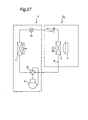
- Fig. 27 shows a refrigerant circuit of an air conditioner equipped with the indoor unit Z 0
- arrow W in the broken line indicates the direction of the flow of a refrigerant when heating
- arrow C in the solid line indicates the direction of the flow of the refrigerant when cooling.
- the indoor unit Z 0 is constructed as follows: in a rectangular-shaped casing 1 having an air inlet 2 in the front surface 1a, an upper surface air outlet 3 in the upper surface 1b and side surface air outlets 4 in the side surfaces 1c, 1c, centrifugal fans 5, 5 are disposed with their suction sides directed to the air inlet 2, and a heat exchanger 6 is positioned between the suction side of the fans 5 and the inlet 2. Indoor air sucked by the fans 5 through the air inlet 2 is heat exchanged by the heat exchanger 6 to give cooled or warmed air. The resultant cooled or warmed air is blown upward from the upper surface air outlet 3 or blown sideways from the side surface air outlets 4, 4 respectively. As shown in Fig.
- this indoor unit Z 0 is connected to an outdoor unit Y equipped with a compressor 9, a direction switching valve 10, an outdoor-side heat exchanger 11 and a main expansion valve 12, via refrigerant piping (collectively referred to as P), thus constituting an air conditioner.
- such a low-place installation type conventional indoor unit Z 0 has a structure in which the heat exchanger 6 is positioned on the suction side of the fans 5, and the upper surface air outlet 3 and the side surface air outlets 4, 4 directly face the discharge side of the fans 5. Therefore, in both of the heating operation shown in Fig. 28 and the cooling operation shown in Fig. 29, sucked air Aa is heat exchanged by the heat exchanger 6 and then blown through the upper surface air outlet 3 as upper outlet air Ab and blown through the upper side surface air outlets 4 as side outlet air Ac.
- the upper outlet air and the side outlet air have the same temperature.
- the upper outlet air Ab from the upper surface air outlet 3 and the side outlet air Ac from the side surface air outlets 4 form an air barrier by the window or by the wall thereby achieving a function of controlling entry of heat radiation.
- the temperature on the floor side is lowered in the heating operation due to rising of warm air from the indoor floor, while cold air is liable to remain on the floor side in the cooling operation.
- realization of a "cooling a head and warming feet" ambience which is an ambience of an ideal temperature distribution, is difficult, and there was a problem of impairing a comfortable air conditioning.
- the present invention was made with the object of realizing a "cooling a head and warming feet" ambience of ideal temperature distribution a without a sense of draft and improving comfortableness of air conditioning in a low-place installation type conventional indoor unit.
- an indoor unit for an air conditioner comprising a casing having an air inlet in a front surface, an upper surface air outlet in an upper surface and a side surface air outlet in a side surface and installed on an indoor floor or in the vicinity of the indoor floor, and a fan and a heat exchanger that are disposed in the casing such that the heat exchanger lies on a suction side of the fan
- the indoor unit of the present invention further comprises a means for regulating a temperature of either upper outlet air from the upper surface air outlet or side outlet air from the side surface air outlet such that the temperature of the upper outlet air is lower than the temperature of the side outlet air.
- the means for regulating a temperature of either upper outlet air from the upper surface air outlet or side outlet air from the side surface air outlet comprises a second heat exchanger within the casing, and the heat exchanger (referred to as the "first heat exchanger" below) is positioned upstream in a direction of airflow, while the second heat exchanger is positioned downstream in the direction of airflow, and the second heat exchanger faces any one of the upper surface air outlet and the side surface air outlet.
- the air to be blown upward through the upper surface air outlet passes both the first heat exchanger and the second heat exchanger to be cooled by both of them. Therefore, the temperature of the air becomes lower than that of air to be blown sideways through the side surface air outlet, the latter passing only the first heat exchanger.
- the cooler air is blown to the upper part of the room, while the relatively warm air is blown to the lower part of the room. Therefore, the "cooling a head and warming feet" state is realized, and a comfortable cooled sensation is obtained by efficiently suppressing cold air gathered at one's feet. That is, an operation that lays stress on the comfortableness in cooling is realized.
- the second heat exchanger may be formed integrally with or separately from the first heat exchanger. In the case where they are formed integrally, it is possible to reduce the production costs by reduction in the number of components or in the number of assembling process steps to thereby provide an indoor unit inexpensively. On the other hand, when the first and second heat exchangers are formed separately, or as separate pieces, the freedom of layout of the first and second heat exchangers relative to the casing is improved, so that it is possible to easily address diversification of needs regarding the indoor unit configuration
- the second heat exchanger is disposed facing the upper surface air outlet, and the second heat exchanger is made to function as an evaporator on a low-pressure side in a cooling operation, and, in a heating operation, as an evaporator on a side a little closer to a high-pressure side than in the cooling operation.
- a relatively low-temperature air which was first heated by the first heat exchanger and then cooled by the second heat exchanger functioning as the evaporator on the side closer to the low-pressure side than the first heat exchanger, is blown out from the upper surface air outlet.
- a relatively high-temperature air only heated by the first heat exchanger is blown out from the side surface air outlet.
- the second heat exchanger is disposed facing the side surface air outlet, and the second heat exchanger is made to function as a condenser on a high-pressure side in a heating operation, and, in a cooling operation, as an evaporator on a side a little closer to a low-pressure side than in the heating operation.
- a high-temperature air heated by the first heat exchanger and further heated by the second heat exchanger is blown from the side surface air outlet.
- a relatively low-temperature air heated by only the first heat exchanger is blown from the upper surface air outlet.
- the heat exchanger and/or the second heat exchanger may be constructed of a stack type heat exchanger comprising a plurality of flat heat exchanger tubes and a plurality of fins being alternately stacked, with both end portions of each of the flat heat exchanger tubes being connected by headers, respectively.
- the characteristics of the stack-type heat exchanger make it possible to reduce the thickness of the heat exchanger, as compared with the case where each of the first heat exchanger and the second heat exchanger is constructed of a cross-fin type heat exchanger, for example. As a result, it becomes possible to achieve both downsizing and improvement in the performance of the indoor unit.
- the means for regulating a temperature of either upper outlet air from the upper surface air outlet or side outlet air from the side surface air outlet comprises a heater provided at the side surface air outlet.
- the temperature of the air heated by the heat exchanger and blown upward from the upper surface air outlet is lower than that of the air heated by both the heat exchanger and the heater and blown sideways from the side surface air outlet. Therefore, a relatively high-temperature air in the lower part of the room is prevented from rising by a relatively low-temperature air in the upper part of the room. This realizes "cooling a head and warming feet", and a comfortable heating sensation is obtained.
- the means for regulating a temperature of either upper outlet air from the upper surface air outlet or side outlet air from the side surface air outlet comprises a circulation system which makes indoor air bypass the heat exchanger and blows indoor air toward the upper surface and/or the side surface.
- the indoor air is blown toward the upper surface of the casing by the circulation system
- the air heated by the heat exchanger and the indoor air from the circulation system are mixed and blown upward from the upper surface air outlet, whereby the temperature of the air blown upward is relatively low.
- a relatively high-temperature air heated by the heat exchanger is let out through the side surface air outlet. Therefore, the relatively high-temperature air in the lower part of the room is restrained from rising by the relatively low-temperature air in the upper part of the room. This realizes "cooling a head and warming feet", and a comfortable heating sensation is obtained. That is, an operation that places importance on comfortableness in heating is obtained.
- Fig. 1 shows an indoor unit Z of a separate type air conditioner for which the present invention is intended.
- this indoor unit Z is a floor installation type indoor unit, which is preferably installed in a perimeter zone having a particularly high air conditioning load in the interior of a room, such as in a region in the vicinity of a window part 53, so as to contrive a reduction in the air conditioning load.
- the indoor unit is installed on an indoor floor 51 against a room wall 52 below of the window part 53, and performs indoor air conditioning by blowing conditioned airflow upward and sideways at the same time, while suppressing entry of radiant heat from the window part 53 and so on.
- the indoor unit Z has a rectangular casing 1 that is advantageous to installation against a wall surface.
- the front surface 1a, the upper surface 1b, and the left and right side surfaces 1c, 1c of the casing 1 are provided with an air inlet 2, an upper surface air outlet 3, and side surface air outlets 4, 4, respectively.
- the present invention further comprises a means for regulating the temperature of either of the upper outlet air Ab from the upper surface air outlet 3 or the side outlet air Ac from the side surface air outlets 4 so that the temperature of the upper outlet air Ab from the upper outlet 3 is lower than the temperature of the side outlet air Ac from the side surface air outlets 4.
- a second heat exchanger 7 for the upper surface air outlet 3 or of the second heat exchangers 8 for the side surface air outlets 4 is made in accordance with required conditions such as indoor air conditioning characteristics so that the comfortableness in cooling and heating is enhanced.
- the sucked air Aa passes the first heat exchanger 6 and then one part of the sucked air further passes the second heat exchangers 8 and is blown sideways from the side surface air outlets 4 as the side outlet air, while another part is blown upward from the upper surface air outlet 3 as the upper outlet air Ab.
- the indoor unit for an air conditioner of the present invention will be specifically described below based on the preferred embodiments.
- an indoor unit Z 1 of a first embodiment is structured such that the first heat exchanger 6 is disposed in correspondence with the air inlet 2 of the casing 1, and that, of the upper surface air outlet 3 and the right and left side surface air outlets 4, the second heat exchangers 8 are provided for the respective side surface air outlets 4, 4. Therefore, with the operation of the fans 5, 5, the sucked air Aa sucked from the air inlet 2 pass the first heat exchanger 6 and then, one part of the sucked air is blown as it is from the upper surface air outlet 3 as the upper outlet air Ab, while another part of the sucked air further passes the second heat exchanger 8 and is blown from the side surface air outlet 4 as the side outlet air Ac.
- FIG. 3 The constitution of a refrigerant circuit of the whole air conditioner including the indoor unit Z 1 is shown in Fig. 3.
- This air conditioner is composed of the indoor unit Z 1 and an outdoor unit Y connected to each other via refrigerant piping P.
- the outdoor unit Y is provided with a compressor 9, a direction switching valve 10, an outdoor heat exchanger 11 and an expansion valve 12, while the indoor unit Z 1 is provided with the first heat exchanger 6 and the second heat exchangers 8.
- the arrangement of the first heat exchanger 6 and the second heat exchangers 8 is set so that the second heat exchangers 8 are positioned on the upstream side of the first heat exchanger 6 in the circulation direction of the refrigerant in the cycle of cooling operation.
- the second heat exchangers 8 are disposed on the side of the side surface air outlets 4, and no heat exchanger is provided on the side of the upper surface air outlet 3. Therefore, in both heating and cooling operations, the side outlet air Ac to be blown from the side surface air outlet 4 is subjected to heat exchange by the first heat exchanger 6 and the second heat exchanger 8, while the upper outlet air Ab to be blown from the upper surface air outlet 3 is subjected to heat exchange by only the first heat exchanger 6. As a result, a temperature difference arises between the side outlet air Ac and the upper outlet air Ab.
- This indoor unit Z 1 is intended to improve the comfortableness particularly in heating operations, using this temperature difference between the side outlet air Ac and the upper outlet air Ab efficiently.
- the upper outlet air Ab to be blown from the upper surface air outlet 3 is subjected to heating by only the first heat exchanger 6, and the side outlet air Ac to be blown from the side surface air outlets 4 is subjected to heating by both of the first heat exchanger 6 and the second heat exchanger 8. Therefore, the upper outlet air Ab has a relatively low temperature, while the side outlet air Ac has a relatively high temperature. As a result, the air having a relatively high temperature is present in the vicinity of the floor 51, or a lower part of the room, and the air having a relatively low temperature is present in an upper part of the room. Thus, rising of the air.
- a low-temperature air subjected to cooling by the first heat exchanger 6 and the second heat exchanger 8 is blown from the side surface air outlets 4 as the side outlet air Ac.
- a relatively high-temperature air cooled by only the first heat exchanger 6 is blown from the upper surface air outlet 3 as the upper outlet air Ab.
- the side surface air outlets 4 may be closed, or the side surface air outlet 4 may be opposed to a wall with little interval therebetween so that the discharge of the side outlet air Ac from the side surface air outlet 4 is suppressed.
- the first heat exchanger 6 and the second heat exchangers 7, 8 a "cross-fin type heat exchanger" is generally adopted.
- the first heat exchanger 6 and/or the second heat exchanger 7, 8 is composed of a stack-type heat exchanger 30 comprising a plurality of flat heat exchanger tubes 31, 31, ⁇ , and a plurality of corrugated fins 32, 32, ⁇ , which are alternately stacked, both end portions of each of the flat heat exchanger tubes 31 being connected by headers 33, 34 respectively.
- paired fans 5, 5 are disposed at a predetermined lateral distance within a casing 1 as in the present embodiment, such fans 5, 5 are arranged to rotate in the same direction.
- obliquely downward velocity components of the side outlet air Ac blown from the side surface air outlets 4 increase, and a sense of downdraft increases particularly in the cooling operation. Therefore, such an arrangement is not preferred in view of comfortableness.
- the indoor unit so that the numbers of revolutions of the fans 5, 5 are independently controlled.
- zoning according to the demand for air conditioning becomes available; e.g., the number of revolutions of the fan 5 positioned on the side closer to a region where someone is present may be set higher, while the number of revolutions of the fan 5 positioned on the side closer to a region where no one is present may be set lower, and so on.
- zoning according to the demand for air conditioning becomes available; e.g., the number of revolutions of the fan 5 positioned on the side closer to a region where someone is present may be set higher, while the number of revolutions of the fan 5 positioned on the side closer to a region where no one is present may be set lower, and so on.
- Fig. 7 shows a refrigerant circuit of the whole air conditioner provided with an indoor unit Z 2 of a second embodiment of the present invention.
- the refrigerant path is set so that the first heat exchanger 6 is positioned downstream of the heat exchangers 8 in the cooling cycle.
- a refrigerant path is set so that the first heat exchanger 6 is positioned upstream of the second heat exchangers 8 in the cooling cycle.
- an indoor unit Z 3 of a third embodiment is structured such that the first heat exchanger 6 is disposed in correspondence with the air inlet 2 of the casing 1, and that, of the upper surface air outlet 3 and the right and left side surface air outlets 4, the second heat exchanger 7 being provided for the upper surface air outlet 3. Therefore, with the operation of the fans 5, 5, the sucked air Aa sucked through the air inlet 2 passes the first heat exchanger 6 and then a part of the sucked air is blown as it is from the side surface air outlets 4 as the side outlet air Ac, while another part of the sucked air further passes the second heat exchanger 7 and is blown from the upper surface air outlet 3 as the upper outlet air Ab.
- FIG. 11 The constitution of a refrigerant circuit of the whole air conditioner including the indoor unit Z 3 is shown in Fig. 11.
- This air conditioner is composed of the indoor unit Z 3 and an outdoor unit Y connected to each other via refrigerant piping P.
- the outdoor unit Y is provided with a compressor 9, a direction switching valve 10, an outdoor heat exchanger 11 and an expansion valve 12, while the indoor unit Z 3 is provided with the first heat exchanger 6 and the second heat exchanger 8.
- the first heat exchanger 6 and the second heat exchanger 7 are arranged such that the second heat exchanger 7 is positioned downstream of the first heat exchanger 6 in the circulation direction of the refrigerant in the cooling operation cycle.
- the second heat exchanger 7 is disposed on the side of the upper surface air outlet 3, and no heat exchanger is provided on the side of side surface air outlets 4. Therefore, in both of the heating operation and the cooling operation, the upper outlet air Ab to be blown from the upper surface air outlet 3 is subjected to heat exchange by the first heat exchanger 6 and the second heat exchanger 7, while the side outlet air Ac to be blown from the side surface air outlets 4 is subjected to heat exchange by only the first heat exchanger 6. As a result, a temperature difference arises between the side outlet air Ac and the upper outlet air Ab.
- This indoor unit Z 3 is intended to improve the comfortableness particularly in cooling, using this temperature difference between the side outlet air Ac and the upper outlet air Ab efficiently.
- the side outlet air Ac to be blown from the side surface air outlets 4 is subjected to a cooling action by only the first heat exchanger 6, and the upper outlet air Ab to be blown from the upper surface air outlet 3 is subjected to a cooling action by both of the first heat exchanger 6 and the second heat exchanger 7. Therefore, the upper outlet air Ab is set to a relatively low temperature, while the side outlet air Ac is set to a relatively high temperature.
- cooler air is blown to an upper part of the room, while relatively warm air is blown to a lower part of the room. This realizes the "cooling a head and warming feet" ambience, and a comfortable cooling sensation can be obtained by efficiently restraining cold air from gathering at one's feet. That is, the operation that lays stress on the comfortableness in cooling is realized.
- a high-temperature air subjected to heating by the first heat exchanger 6 and the second heat exchanger 7 is blown from the upper surface air outlet 3 as the upper outlet air Ab.
- a relatively low-temperature air heated by only the first heat exchanger 6 is blown from the side surface air outlets 4 as the side outlet air Ac.
- the upper surface air outlet 3 may be closed so that the output of the upper outlet air Ab from the upper surface air outlet 3 is controlled.
- Fig. 14 shows a refrigerant circuit of the whole air conditioner provided with an indoor unit Z 4 of a fourth embodiment of the present invention.
- the refrigerant path is set so that the first heat exchanger 6 is positioned upstream of the heat exchanger 7 in the cooling cycle.
- a refrigerant path is set so that the first heat exchanger 6 is positioned downstream of the second heat exchanger 7 in the circulation direction of the refrigerant in the cooling cycle.
- This embodiment is directed to an indoor unit structured such that, in the same manner as in the indoor unit Z 1 of the first embodiment, the first heat exchanger 6 is disposed in correspondence with the air inlet 2 of the casing 1, and that, of the upper surface air outlet 3 and the right and left side surface air outlets 4, 4, the second heat exchangers 8 are provided for the respective side surface air outlets 4, 4 (see Fig. 2). Therefore, with the operation of the fans 5, 5, the sucked air A a sucked from the air inlet 2 passes the first heat exchanger 6 and then one part of the sucked air is blown as it is from the upper surface air outlet 3 as the upper outlet air Ab, while another part further passes the second heat exchanger 8 and is output from the side surface air outlet 4 as the side outlet air Ac.
- FIG. 17 The constitution of a refrigerant circuit of the whole air conditioner including the indoor unit Z 5 is shown in Fig. 17.
- This air conditioner is composed of the indoor unit Z 5 and an outdoor unit Y connected to each other via refrigerant piping P.
- a compressor 9, a direction switching valve 10, an outdoor-side heat exchanger 11 and an expansion valve 12 are provided in the outdoor unit Y, while the indoor unit Z 5 is provided with the first heat exchanger 6 and the second heat exchangers 8.
- the first heat exchanger 6 is connected via an auxiliary expansion valve 13 to the second heat exchangers 8, and the first heat exchanger 6 and the second heat exchangers 8 are arranged such that the second heat exchangers 8 are located upstream of the first heat exchanger 6 in the circulation direction of the refrigerant in the cycle of cooling operation.
- Operative relationships between the auxiliary expansion valve 13 and the main expansion valve 12 in the outdoor unit Y are set in a relative manner. That is, in the heating operation, the main expansion valve 12 is set to “throttled” and the auxiliary expansion valve 13 is set to “full open”. On the other hand, in the cooling operation, the main expansion valve 12 is set to "slightly throttled” and the auxiliary expansion valve 13 is set to "throttled”.
- both of the first heat exchanger 6 and the second heat exchangers 8 function as compressors on the high-pressure side.
- a relatively low-temperature air heated by only the first heat exchanger 6 is blown upward from the upper surface air outlet 3 as the upper outlet air Ab
- a relatively high-temperature air heated by both the first heat exchanger 6 and the second heat exchanger 8 is blown sideways from the side surface air outlet 4 as the side outlet air Ac.
- the main expansion valve 12 is set to "slightly throttled” and the auxiliary expansion valve 13 is set to "throttled”. Therefore, as shown in Fig. 19, the first heat exchanger 6 functions as an evaporator on the low-pressure side, while the second heat exchangers 8 function as evaporators at an intermediate pressure between the high-pressure side and the low-pressure side.
- a relatively low-temperature air cooled by only the first heat exchanger 6 is blown upward from the upper surface air outlet 3 as the upper outlet air Ab, while a relatively high-temperature air is blown sideways from the side surface air outlets 4 as the side outlet air Ac, which was first cooled by the first heat exchanger 6 and then cooled by the second heat exchanger 8 having a temperature higher than the first heat exchanger 6 so that the temperature of the air is raised.
- the "cooling a head and warming feet" ambience that is an ideal temperature distribution ambience is realized.
- a comfortable cooling sensation is obtained by controlling cold air remaining at one's feet efficiently.
- the indoor unit Z 5 is provided with the second heat exchangers 8 on the sides of the side surface air outlets 4, and the second heat exchangers 8 are positioned upstream of the first heat exchanger 6, with the auxiliary expansion valve 13 disposed therebetween, in the circulation direction of the refrigerant in the cycle of cooling operation.
- the second heat exchanger 7 is provided on the side of the upper surface air outlet 3, and the heat exchanger 7 is disposed upstream of the first heat exchanger 6 in the circulation direction of the refrigerant.
- operative relationships between the auxiliary expansion valve 13 and the main expansion valve 12 in the outdoor unit Y are set in a relative manner. That is, in the heating operation, the main expansion valve 12 is set to “throttled” and the auxiliary expansion valve 13 is set to “slightly throttled”. On the other hand, in the cooling operation, the main expansion valve 12 is set to "throttled” and the auxiliary expansion valve 13 is set to "full open”.
- the main expansion valve 12 is set to "throttled” and the auxiliary expansion valve 13 is set to "slightly throttled”. Therefore, as shown in Fig. 21, the first heat exchanger 6 functions as an evaporator on the high-pressure side, and the second heat exchanger 7 functions as an evaporator at an intermediate pressure between the high-pressure side and the low-pressure side.
- the upper outlet air Ab blown from the upper surface air outlet 3 was heated by the first heat exchanger 6 and then cooled by passing the second heat exchanger functioning as the evaporator at an intermediate pressure to give a relatively low-temperature air.
- the side outlet air Ac blown sideways from the side surface air outlet 4 was only heated by the first heat exchanger 6, and thus the temperature of the air is relatively high. Therefore, the air having a relatively high temperature is present in a lower part of the room, while in an upper part of the room, the air having a relatively low temperature is present. As a result, the "cooling a head and warming feet" state of an ideal temperature distribution is realized, and a comfortable heating sensation is obtained by efficiently restraining cold air from gathering at one's feet.
- both of the first heat exchanger 6 and the second heat exchanger 7 function as evaporators on the low-pressure side.
- the upper outlet air Ab blown from the upper surface air outlet 3 was cooled by both of the first heat exchanger 6 and the second heat exchanger 7, while the side outlet air Ac blown from the side surface air outlets 4 was cooled by only the first heat exchanger 6.
- the air having a relatively low temperature is present in the upper part of the room, while the air having a relatively high temperature is present in the lower part of the room.
- the "cooling a head and warming feet" ambience that is an ideal temperature distribution ambience is realized, and a comfortable cooling sensation is obtained by efficiently restraining cold air from gathering at one's feet.
- the comfortableness in cooling or heating is achieved by providing heaters 15 on the air outlet sides of the fans 5.
- the indoor unit Z 7 as shown in Fig. 23, only the first heat exchanger 6 is disposed on the suction side of the fans 5.
- the heaters 15 are disposed at the side surface air outlets 4. The heaters 15 are energized in both the heating operation and the cooling operation.
- a relatively high-temperature air first heated by the first heat exchanger 6 and further heated by the heaters 15 is blown from the side surface air outlets 4 as the side outlet air Ac, and a relatively low-temperature air heated only by the first heat exchanger 6 is blown from the upper surface air outlet 3.
- the air having a relatively low temperature is present in the upper part of the room, while the air having a relatively high temperature is present in the lower part of the room, so that the relatively high-temperature air in the lower part of the room is restrained from rising by the relatively low-temperature air in the upper part of the room. Therefore, a "cooling a head and warming feet" ambience is realized, and a comfortable heating sensation is obtained.
- a relatively high-temperature air cooled by the first heat exchanger 6 and then heated by the heater 15 is blown from the side surface air outlet 4 as the side outlet air Ac, while a relatively low-temperature air only cooled by the first heat exchanger 6 is blown from the upper surface air outlet 3.
- the air having a relatively high temperature is present in the lower part of the room, while the air having a relatively low temperature is present in the upper part of the room. Therefore, a "cooling a head and warming feet" ambience that is an ideal thermal space is realized. Accordingly, a comfortable cooling sensation can be obtained, with the cold air gathering at one's feet efficiently suppressed.
- Fig. 24 shows an indoor unit Z 8 of an eighth embodiment.
- the indoor air namely, air having a temperature lower than that of the conditioned air blown from the indoor unit in the heating operation, and air having a temperature higher than that of the conditioned air in the cooling operation
- the indoor air is made to detour or bypass the heat exchanger 6 and return to the inside of the room.
- the indoor unit Z 8 has a circulation system X composed of a curved bypass 20 extending from the upper part of the air inlet 2 to the vicinity of the upper surface air outlet 3 of the upper surface of the casing 1 and a fan 21 disposed within the bypass 20.
- the upper outlet air Ab heated by the first heat exchanger 6 and then blown upward from the upper surface air outlet 3 is mixed with the indoor air Ab' blown upward from the vicinity of the upper surface air outlet 3 by the circulation system X, whereby the upper discharge temperature is made relatively low.
- the air heated by the first heat exchanger which has a relatively high temperature
- the side surface air outlets 4 as the side outlet air Ac.
- Fig. 25 shows an indoor unit Z 9 of a ninth embodiment.
- the indoor unit Z 8 of the eighth embodiment lays stress on the comfortableness in the heating operation, while this indoor unit Z 9 lays stress on the comfortableness in the cooling operation.
- the indoor unit Z 9 has circulation systems X each composed of a bypass 22 detouring the heat exchanger 6 to provide communication between the air inlet 2 and the vicinity of the corresponding side surface air outlet 4, and a fan 23 provided within the bypass 22.
Landscapes
- Engineering & Computer Science (AREA)
- Mechanical Engineering (AREA)
- General Engineering & Computer Science (AREA)
- Chemical & Material Sciences (AREA)
- Combustion & Propulsion (AREA)
- Physics & Mathematics (AREA)
- Thermal Sciences (AREA)
- Air Filters, Heat-Exchange Apparatuses, And Housings Of Air-Conditioning Units (AREA)
- Devices For Blowing Cold Air, Devices For Blowing Warm Air, And Means For Preventing Water Condensation In Air Conditioning Units (AREA)
- Air Humidification (AREA)
Applications Claiming Priority (3)
| Application Number | Priority Date | Filing Date | Title |
|---|---|---|---|
| JP2001006296A JP3624836B2 (ja) | 2001-01-15 | 2001-01-15 | 空気調和機の室内機 |
| JP2001006296 | 2001-01-15 | ||
| PCT/JP2001/011318 WO2002055937A1 (fr) | 2001-01-15 | 2001-12-25 | Unite interieure pour conditionneur d'air |
Publications (3)
| Publication Number | Publication Date |
|---|---|
| EP1361398A1 true EP1361398A1 (de) | 2003-11-12 |
| EP1361398A4 EP1361398A4 (de) | 2007-03-07 |
| EP1361398B1 EP1361398B1 (de) | 2009-03-11 |
Family
ID=18874201
Family Applications (1)
| Application Number | Title | Priority Date | Filing Date |
|---|---|---|---|
| EP01273084A Expired - Lifetime EP1361398B1 (de) | 2001-01-15 | 2001-12-25 | Innenraumeinheit für klimaanlage |
Country Status (7)
| Country | Link |
|---|---|
| EP (1) | EP1361398B1 (de) |
| JP (1) | JP3624836B2 (de) |
| AT (1) | ATE425420T1 (de) |
| AU (1) | AU2002219519B9 (de) |
| DE (1) | DE60137968D1 (de) |
| ES (1) | ES2322022T3 (de) |
| WO (1) | WO2002055937A1 (de) |
Cited By (16)
| Publication number | Priority date | Publication date | Assignee | Title |
|---|---|---|---|---|
| EP1580491A1 (de) * | 2004-03-04 | 2005-09-28 | Lg Electronics Inc. | Innenraumeinheit einer Klimaanlage |
| EP1772678A1 (de) * | 2005-10-05 | 2007-04-11 | LG Electronics Inc. | Vorrichtung zum Umlenken eines Luftstroms und Klimaanlage mit dieser Vorrichtung |
| CN100455910C (zh) * | 2004-06-21 | 2009-01-28 | 乐金电子(天津)电器有限公司 | 空调器的室内机 |
| EP1628082A3 (de) * | 2004-08-19 | 2009-02-18 | LG Electronics Inc. | Selbsttragende Klimaanlage |
| AU2006209087B2 (en) * | 2005-01-27 | 2009-07-30 | Lg Electronics, Inc. | Indoor unit of air conditioner |
| FR2947040A1 (fr) * | 2009-06-23 | 2010-12-24 | Cinier Radiateurs | Radiateur reversible |
| EP2551607A1 (de) * | 2011-07-28 | 2013-01-30 | LG Electronics, Inc. | Lüftungsgerät |
| CN103574863A (zh) * | 2012-07-25 | 2014-02-12 | 珠海格力电器股份有限公司 | 空调室内机 |
| CN104214920A (zh) * | 2014-09-19 | 2014-12-17 | 珠海格力电器股份有限公司 | 空调器出风结构和空调器 |
| EP1673580B1 (de) * | 2004-08-16 | 2016-01-06 | Bernd Löffler | Arbeitsraumluftkühler |
| US20160040896A1 (en) * | 2014-08-05 | 2016-02-11 | Samsung Electronics Co., Ltd. | Air conditioner |
| EP3382287A1 (de) * | 2017-03-31 | 2018-10-03 | Mitsubishi Electric R&D Centre Europe B.V. | Lüfterspuleneinheit |
| US20190003727A1 (en) * | 2016-01-07 | 2019-01-03 | Samsung Electronics Co., Ltd. | Air conditioner |
| US20190178506A1 (en) * | 2016-06-17 | 2019-06-13 | Güntner Gmbh & Co. Kg | Cooling device for installation under a room ceiling |
| CN112212408A (zh) * | 2020-10-20 | 2021-01-12 | 青岛海信日立空调系统有限公司 | 空调室内机 |
| CN112283800A (zh) * | 2020-09-16 | 2021-01-29 | 珠海格力电器股份有限公司 | 一种空调室内机和空调器 |
Families Citing this family (9)
| Publication number | Priority date | Publication date | Assignee | Title |
|---|---|---|---|---|
| KR20040042163A (ko) * | 2002-11-13 | 2004-05-20 | 주식회사 대우일렉트로닉스 | 공기조화기의 실내기 |
| JP4529530B2 (ja) * | 2004-04-26 | 2010-08-25 | ダイキン工業株式会社 | 調湿装置 |
| JP2006336910A (ja) * | 2005-05-31 | 2006-12-14 | Daikin Ind Ltd | 空気調和機用室内ユニット |
| CN104296243A (zh) * | 2014-09-30 | 2015-01-21 | 美的集团武汉制冷设备有限公司 | 室内挂机及具有其的空调器 |
| CN105757802A (zh) * | 2016-04-19 | 2016-07-13 | 宁波奥克斯空调有限公司 | 一种壁挂式空调 |
| CN113154530A (zh) * | 2017-09-12 | 2021-07-23 | 广东美的制冷设备有限公司 | 空调器 |
| WO2019052192A1 (zh) * | 2017-09-12 | 2019-03-21 | 广东美的制冷设备有限公司 | 空调器 |
| US11391494B2 (en) * | 2020-08-10 | 2022-07-19 | Donald Eugene Smith | Multiple directional blow unit cooler |
| CN112902377B (zh) * | 2021-02-10 | 2022-02-18 | 珠海格力电器股份有限公司 | 空调器的控制系统 |
Citations (2)
| Publication number | Priority date | Publication date | Assignee | Title |
|---|---|---|---|---|
| JPH10141741A (ja) * | 1996-11-15 | 1998-05-29 | Daikin Ind Ltd | 空気調和機 |
| EP1041351A1 (de) * | 1997-12-18 | 2000-10-04 | Daikin Industries, Limited | Innenraumeinheit für eine klimaanlage |
Family Cites Families (6)
| Publication number | Priority date | Publication date | Assignee | Title |
|---|---|---|---|---|
| JPS5596329U (de) * | 1978-12-26 | 1980-07-04 | ||
| JPS63187028A (ja) * | 1987-01-29 | 1988-08-02 | Toshiba Corp | 空気調和機 |
| JPH06241491A (ja) * | 1993-02-12 | 1994-08-30 | Sharp Corp | 熱交換器の取り付け構造 |
| JP3283706B2 (ja) * | 1994-10-03 | 2002-05-20 | 東芝キヤリア株式会社 | 空気調和装置 |
| JPH09264557A (ja) * | 1996-03-26 | 1997-10-07 | Daikin Ind Ltd | 空気調和装置 |
| JP2947236B2 (ja) * | 1997-08-08 | 1999-09-13 | ダイキン工業株式会社 | 空気調和機の吹出口構造 |
-
2001
- 2001-01-15 JP JP2001006296A patent/JP3624836B2/ja not_active Expired - Fee Related
- 2001-12-25 ES ES01273084T patent/ES2322022T3/es not_active Expired - Lifetime
- 2001-12-25 EP EP01273084A patent/EP1361398B1/de not_active Expired - Lifetime
- 2001-12-25 DE DE60137968T patent/DE60137968D1/de not_active Expired - Lifetime
- 2001-12-25 AT AT01273084T patent/ATE425420T1/de not_active IP Right Cessation
- 2001-12-25 WO PCT/JP2001/011318 patent/WO2002055937A1/ja active IP Right Grant
- 2001-12-25 AU AU2002219519A patent/AU2002219519B9/en not_active Ceased
Patent Citations (2)
| Publication number | Priority date | Publication date | Assignee | Title |
|---|---|---|---|---|
| JPH10141741A (ja) * | 1996-11-15 | 1998-05-29 | Daikin Ind Ltd | 空気調和機 |
| EP1041351A1 (de) * | 1997-12-18 | 2000-10-04 | Daikin Industries, Limited | Innenraumeinheit für eine klimaanlage |
Non-Patent Citations (1)
| Title |
|---|
| See also references of WO02055937A1 * |
Cited By (27)
| Publication number | Priority date | Publication date | Assignee | Title |
|---|---|---|---|---|
| EP1580491A1 (de) * | 2004-03-04 | 2005-09-28 | Lg Electronics Inc. | Innenraumeinheit einer Klimaanlage |
| US7181925B2 (en) | 2004-03-04 | 2007-02-27 | Lg Electronics Inc. | Indoor unit in air conditioner |
| CN100455910C (zh) * | 2004-06-21 | 2009-01-28 | 乐金电子(天津)电器有限公司 | 空调器的室内机 |
| EP1673580B1 (de) * | 2004-08-16 | 2016-01-06 | Bernd Löffler | Arbeitsraumluftkühler |
| EP1628082A3 (de) * | 2004-08-19 | 2009-02-18 | LG Electronics Inc. | Selbsttragende Klimaanlage |
| AU2006209087B2 (en) * | 2005-01-27 | 2009-07-30 | Lg Electronics, Inc. | Indoor unit of air conditioner |
| EP1772678A1 (de) * | 2005-10-05 | 2007-04-11 | LG Electronics Inc. | Vorrichtung zum Umlenken eines Luftstroms und Klimaanlage mit dieser Vorrichtung |
| CN100549549C (zh) * | 2005-10-05 | 2009-10-14 | Lg电子株式会社 | 风向调节装置及具备该风向调节装置的空气调节器 |
| CN102439369B (zh) * | 2009-06-23 | 2014-10-22 | 西尼耶散热器责任有限公司 | 可逆的辐射器 |
| WO2010149865A1 (fr) * | 2009-06-23 | 2010-12-29 | Cinier Radiateurs, Sarl | Radiateur reversible |
| CN102439369A (zh) * | 2009-06-23 | 2012-05-02 | 西尼耶散热器责任有限公司 | 可逆的辐射器 |
| FR2947040A1 (fr) * | 2009-06-23 | 2010-12-24 | Cinier Radiateurs | Radiateur reversible |
| US9234666B2 (en) | 2009-06-23 | 2016-01-12 | Michel Cinier | Heat transfer apparatus for heating and cooling a room |
| EP2551607A1 (de) * | 2011-07-28 | 2013-01-30 | LG Electronics, Inc. | Lüftungsgerät |
| CN103574863B (zh) * | 2012-07-25 | 2016-12-21 | 珠海格力电器股份有限公司 | 空调室内机 |
| CN103574863A (zh) * | 2012-07-25 | 2014-02-12 | 珠海格力电器股份有限公司 | 空调室内机 |
| US20160040896A1 (en) * | 2014-08-05 | 2016-02-11 | Samsung Electronics Co., Ltd. | Air conditioner |
| CN105333500A (zh) * | 2014-08-05 | 2016-02-17 | 三星电子株式会社 | 空调 |
| CN104214920A (zh) * | 2014-09-19 | 2014-12-17 | 珠海格力电器股份有限公司 | 空调器出风结构和空调器 |
| CN104214920B (zh) * | 2014-09-19 | 2017-10-03 | 珠海格力电器股份有限公司 | 空调器出风结构和空调器 |
| US20190003727A1 (en) * | 2016-01-07 | 2019-01-03 | Samsung Electronics Co., Ltd. | Air conditioner |
| US11255551B2 (en) * | 2016-01-07 | 2022-02-22 | Samsung Electronics Co., Ltd. | Air conditioner |
| US20190178506A1 (en) * | 2016-06-17 | 2019-06-13 | Güntner Gmbh & Co. Kg | Cooling device for installation under a room ceiling |
| RU2731072C2 (ru) * | 2016-06-17 | 2020-08-28 | Гюнтнер Гмбх Унд Ко. Кг | Охлаждающее устройство для установки под потолком помещения |
| EP3382287A1 (de) * | 2017-03-31 | 2018-10-03 | Mitsubishi Electric R&D Centre Europe B.V. | Lüfterspuleneinheit |
| CN112283800A (zh) * | 2020-09-16 | 2021-01-29 | 珠海格力电器股份有限公司 | 一种空调室内机和空调器 |
| CN112212408A (zh) * | 2020-10-20 | 2021-01-12 | 青岛海信日立空调系统有限公司 | 空调室内机 |
Also Published As
| Publication number | Publication date |
|---|---|
| ATE425420T1 (de) | 2009-03-15 |
| DE60137968D1 (de) | 2009-04-23 |
| AU2002219519B2 (en) | 2006-02-02 |
| ES2322022T3 (es) | 2009-06-16 |
| JP2002213808A (ja) | 2002-07-31 |
| AU2002219519B9 (en) | 2006-07-06 |
| EP1361398A4 (de) | 2007-03-07 |
| JP3624836B2 (ja) | 2005-03-02 |
| WO2002055937A1 (fr) | 2002-07-18 |
| EP1361398B1 (de) | 2009-03-11 |
Similar Documents
| Publication | Publication Date | Title |
|---|---|---|
| EP1361398B1 (de) | Innenraumeinheit für klimaanlage | |
| US6644049B2 (en) | Space conditioning system having multi-stage cooling and dehumidification capability | |
| US11614285B2 (en) | Interlaced heat exchanger | |
| WO2018047331A1 (ja) | 空気調和装置 | |
| EP1628081B1 (de) | Innenraumeinheit einer Klimaanlage | |
| US20220003504A1 (en) | Heat exchanger for hvac unit | |
| EP2037186B1 (de) | Klimaanlage | |
| CN115264621A (zh) | 一种空调室内机、空调室内机的控制方法和空调器 | |
| CN214949402U (zh) | 空调器室内机 | |
| EP3614061B1 (de) | Klimatisierungssystem | |
| CN215001914U (zh) | 空调器室内机 | |
| JP3589184B2 (ja) | 空気調和機の室内機 | |
| JP6601886B1 (ja) | 空気熱源式ヒートポンプユニット | |
| JP6365649B2 (ja) | 空気調和システム | |
| JP2575861B2 (ja) | 空調換気扇 | |
| WO2023148854A1 (ja) | 熱交換型換気装置 | |
| JP2021008981A (ja) | 空気調和ユニット、熱交換器、および空気調和機 | |
| JP2002235945A (ja) | 空気調和機 | |
| JP3484693B2 (ja) | 空冷ヒートポンプ式蓄熱空調機 | |
| US11994352B2 (en) | Heat exchanger | |
| CN212869971U (zh) | 空调器 | |
| US11054170B2 (en) | Systems and methods for providing airflows across a heat exchanger | |
| WO2022158263A1 (ja) | 壁掛け式の空調室内機、および空気調和装置 | |
| JP3617623B2 (ja) | ヒートポンプ式空調機 | |
| US20230221013A1 (en) | Multiple Fan HVAC System with Optimized Fan Location |
Legal Events
| Date | Code | Title | Description |
|---|---|---|---|
| PUAI | Public reference made under article 153(3) epc to a published international application that has entered the european phase |
Free format text: ORIGINAL CODE: 0009012 |
|
| 17P | Request for examination filed |
Effective date: 20030814 |
|
| AK | Designated contracting states |
Kind code of ref document: A1 Designated state(s): AT BE CH CY DE DK ES FI FR GB GR IE IT LI LU MC NL PT SE TR |
|
| AX | Request for extension of the european patent |
Extension state: AL LT LV MK RO SI |
|
| A4 | Supplementary search report drawn up and despatched |
Effective date: 20070206 |
|
| RIC1 | Information provided on ipc code assigned before grant |
Ipc: F24F 1/00 20060101AFI20020724BHEP Ipc: F25B 13/00 20060101ALI20070131BHEP Ipc: F24F 13/08 20060101ALI20070131BHEP |
|
| 17Q | First examination report despatched |
Effective date: 20071024 |
|
| GRAP | Despatch of communication of intention to grant a patent |
Free format text: ORIGINAL CODE: EPIDOSNIGR1 |
|
| GRAS | Grant fee paid |
Free format text: ORIGINAL CODE: EPIDOSNIGR3 |
|
| GRAA | (expected) grant |
Free format text: ORIGINAL CODE: 0009210 |
|
| AK | Designated contracting states |
Kind code of ref document: B1 Designated state(s): AT BE CH CY DE DK ES FI FR GB GR IE IT LI LU MC NL PT SE TR |
|
| REG | Reference to a national code |
Ref country code: GB Ref legal event code: FG4D |
|
| REG | Reference to a national code |
Ref country code: CH Ref legal event code: EP |
|
| REG | Reference to a national code |
Ref country code: IE Ref legal event code: FG4D |
|
| REF | Corresponds to: |
Ref document number: 60137968 Country of ref document: DE Date of ref document: 20090423 Kind code of ref document: P |
|
| REG | Reference to a national code |
Ref country code: ES Ref legal event code: FG2A Ref document number: 2322022 Country of ref document: ES Kind code of ref document: T3 |
|
| PG25 | Lapsed in a contracting state [announced via postgrant information from national office to epo] |
Ref country code: NL Free format text: LAPSE BECAUSE OF FAILURE TO SUBMIT A TRANSLATION OF THE DESCRIPTION OR TO PAY THE FEE WITHIN THE PRESCRIBED TIME-LIMIT Effective date: 20090311 Ref country code: FI Free format text: LAPSE BECAUSE OF FAILURE TO SUBMIT A TRANSLATION OF THE DESCRIPTION OR TO PAY THE FEE WITHIN THE PRESCRIBED TIME-LIMIT Effective date: 20090311 |
|
| NLV1 | Nl: lapsed or annulled due to failure to fulfill the requirements of art. 29p and 29m of the patents act | ||
| PG25 | Lapsed in a contracting state [announced via postgrant information from national office to epo] |
Ref country code: AT Free format text: LAPSE BECAUSE OF FAILURE TO SUBMIT A TRANSLATION OF THE DESCRIPTION OR TO PAY THE FEE WITHIN THE PRESCRIBED TIME-LIMIT Effective date: 20090311 Ref country code: SE Free format text: LAPSE BECAUSE OF FAILURE TO SUBMIT A TRANSLATION OF THE DESCRIPTION OR TO PAY THE FEE WITHIN THE PRESCRIBED TIME-LIMIT Effective date: 20090611 |
|
| PG25 | Lapsed in a contracting state [announced via postgrant information from national office to epo] |
Ref country code: BE Free format text: LAPSE BECAUSE OF FAILURE TO SUBMIT A TRANSLATION OF THE DESCRIPTION OR TO PAY THE FEE WITHIN THE PRESCRIBED TIME-LIMIT Effective date: 20090311 |
|
| PG25 | Lapsed in a contracting state [announced via postgrant information from national office to epo] |
Ref country code: PT Free format text: LAPSE BECAUSE OF FAILURE TO SUBMIT A TRANSLATION OF THE DESCRIPTION OR TO PAY THE FEE WITHIN THE PRESCRIBED TIME-LIMIT Effective date: 20090824 |
|
| PLBE | No opposition filed within time limit |
Free format text: ORIGINAL CODE: 0009261 |
|
| STAA | Information on the status of an ep patent application or granted ep patent |
Free format text: STATUS: NO OPPOSITION FILED WITHIN TIME LIMIT |
|
| PG25 | Lapsed in a contracting state [announced via postgrant information from national office to epo] |
Ref country code: DK Free format text: LAPSE BECAUSE OF FAILURE TO SUBMIT A TRANSLATION OF THE DESCRIPTION OR TO PAY THE FEE WITHIN THE PRESCRIBED TIME-LIMIT Effective date: 20090311 |
|
| 26N | No opposition filed |
Effective date: 20091214 |
|
| PG25 | Lapsed in a contracting state [announced via postgrant information from national office to epo] |
Ref country code: MC Free format text: LAPSE BECAUSE OF NON-PAYMENT OF DUE FEES Effective date: 20100701 |
|
| REG | Reference to a national code |
Ref country code: CH Ref legal event code: PL |
|
| PG25 | Lapsed in a contracting state [announced via postgrant information from national office to epo] |
Ref country code: LI Free format text: LAPSE BECAUSE OF NON-PAYMENT OF DUE FEES Effective date: 20091231 Ref country code: IE Free format text: LAPSE BECAUSE OF NON-PAYMENT OF DUE FEES Effective date: 20091225 Ref country code: CH Free format text: LAPSE BECAUSE OF NON-PAYMENT OF DUE FEES Effective date: 20091231 Ref country code: GR Free format text: LAPSE BECAUSE OF FAILURE TO SUBMIT A TRANSLATION OF THE DESCRIPTION OR TO PAY THE FEE WITHIN THE PRESCRIBED TIME-LIMIT Effective date: 20090612 |
|
| PG25 | Lapsed in a contracting state [announced via postgrant information from national office to epo] |
Ref country code: LU Free format text: LAPSE BECAUSE OF NON-PAYMENT OF DUE FEES Effective date: 20091225 |
|
| PG25 | Lapsed in a contracting state [announced via postgrant information from national office to epo] |
Ref country code: TR Free format text: LAPSE BECAUSE OF FAILURE TO SUBMIT A TRANSLATION OF THE DESCRIPTION OR TO PAY THE FEE WITHIN THE PRESCRIBED TIME-LIMIT Effective date: 20090311 |
|
| PG25 | Lapsed in a contracting state [announced via postgrant information from national office to epo] |
Ref country code: CY Free format text: LAPSE BECAUSE OF FAILURE TO SUBMIT A TRANSLATION OF THE DESCRIPTION OR TO PAY THE FEE WITHIN THE PRESCRIBED TIME-LIMIT Effective date: 20090311 |
|
| PGFP | Annual fee paid to national office [announced via postgrant information from national office to epo] |
Ref country code: IT Payment date: 20121219 Year of fee payment: 12 Ref country code: GB Payment date: 20121219 Year of fee payment: 12 Ref country code: ES Payment date: 20121219 Year of fee payment: 12 |
|
| PGFP | Annual fee paid to national office [announced via postgrant information from national office to epo] |
Ref country code: FR Payment date: 20130107 Year of fee payment: 12 |
|
| PGFP | Annual fee paid to national office [announced via postgrant information from national office to epo] |
Ref country code: DE Payment date: 20121219 Year of fee payment: 12 |
|
| REG | Reference to a national code |
Ref country code: DE Ref legal event code: R119 Ref document number: 60137968 Country of ref document: DE |
|
| GBPC | Gb: european patent ceased through non-payment of renewal fee |
Effective date: 20131225 |
|
| REG | Reference to a national code |
Ref country code: FR Ref legal event code: ST Effective date: 20140829 |
|
| REG | Reference to a national code |
Ref country code: DE Ref legal event code: R119 Ref document number: 60137968 Country of ref document: DE Effective date: 20140701 |
|
| PG25 | Lapsed in a contracting state [announced via postgrant information from national office to epo] |
Ref country code: DE Free format text: LAPSE BECAUSE OF NON-PAYMENT OF DUE FEES Effective date: 20140701 |
|
| PG25 | Lapsed in a contracting state [announced via postgrant information from national office to epo] |
Ref country code: FR Free format text: LAPSE BECAUSE OF NON-PAYMENT OF DUE FEES Effective date: 20131231 Ref country code: GB Free format text: LAPSE BECAUSE OF NON-PAYMENT OF DUE FEES Effective date: 20131225 |
|
| REG | Reference to a national code |
Ref country code: ES Ref legal event code: FD2A Effective date: 20150429 |
|
| PG25 | Lapsed in a contracting state [announced via postgrant information from national office to epo] |
Ref country code: ES Free format text: LAPSE BECAUSE OF NON-PAYMENT OF DUE FEES Effective date: 20131226 |
|
| PG25 | Lapsed in a contracting state [announced via postgrant information from national office to epo] |
Ref country code: IT Free format text: LAPSE BECAUSE OF NON-PAYMENT OF DUE FEES Effective date: 20131231 |
|
| PG25 | Lapsed in a contracting state [announced via postgrant information from national office to epo] |
Ref country code: IT Free format text: LAPSE BECAUSE OF NON-PAYMENT OF DUE FEES Effective date: 20131225 |