EP1361383A1 - Magnetventil - Google Patents
Magnetventil Download PDFInfo
- Publication number
- EP1361383A1 EP1361383A1 EP02025671A EP02025671A EP1361383A1 EP 1361383 A1 EP1361383 A1 EP 1361383A1 EP 02025671 A EP02025671 A EP 02025671A EP 02025671 A EP02025671 A EP 02025671A EP 1361383 A1 EP1361383 A1 EP 1361383A1
- Authority
- EP
- European Patent Office
- Prior art keywords
- solenoid valve
- component
- projection
- magnetic core
- magnetic
- Prior art date
- Legal status (The legal status is an assumption and is not a legal conclusion. Google has not performed a legal analysis and makes no representation as to the accuracy of the status listed.)
- Withdrawn
Links
Images

Classifications
-
- F—MECHANICAL ENGINEERING; LIGHTING; HEATING; WEAPONS; BLASTING
- F16—ENGINEERING ELEMENTS AND UNITS; GENERAL MEASURES FOR PRODUCING AND MAINTAINING EFFECTIVE FUNCTIONING OF MACHINES OR INSTALLATIONS; THERMAL INSULATION IN GENERAL
- F16K—VALVES; TAPS; COCKS; ACTUATING-FLOATS; DEVICES FOR VENTING OR AERATING
- F16K31/00—Actuating devices; Operating means; Releasing devices
- F16K31/02—Actuating devices; Operating means; Releasing devices electric; magnetic
- F16K31/06—Actuating devices; Operating means; Releasing devices electric; magnetic using a magnet, e.g. diaphragm valves, cutting off by means of a liquid
- F16K31/0644—One-way valve
- F16K31/0651—One-way valve the fluid passing through the solenoid coil
-
- F—MECHANICAL ENGINEERING; LIGHTING; HEATING; WEAPONS; BLASTING
- F02—COMBUSTION ENGINES; HOT-GAS OR COMBUSTION-PRODUCT ENGINE PLANTS
- F02M—SUPPLYING COMBUSTION ENGINES IN GENERAL WITH COMBUSTIBLE MIXTURES OR CONSTITUENTS THEREOF
- F02M26/00—Engine-pertinent apparatus for adding exhaust gases to combustion-air, main fuel or fuel-air mixture, e.g. by exhaust gas recirculation [EGR] systems
- F02M26/52—Systems for actuating EGR valves
- F02M26/53—Systems for actuating EGR valves using electric actuators, e.g. solenoids
-
- F—MECHANICAL ENGINEERING; LIGHTING; HEATING; WEAPONS; BLASTING
- F02—COMBUSTION ENGINES; HOT-GAS OR COMBUSTION-PRODUCT ENGINE PLANTS
- F02M—SUPPLYING COMBUSTION ENGINES IN GENERAL WITH COMBUSTIBLE MIXTURES OR CONSTITUENTS THEREOF
- F02M26/00—Engine-pertinent apparatus for adding exhaust gases to combustion-air, main fuel or fuel-air mixture, e.g. by exhaust gas recirculation [EGR] systems
- F02M26/52—Systems for actuating EGR valves
- F02M26/55—Systems for actuating EGR valves using vacuum actuators
- F02M26/56—Systems for actuating EGR valves using vacuum actuators having pressure modulation valves
- F02M26/57—Systems for actuating EGR valves using vacuum actuators having pressure modulation valves using electronic means, e.g. electromagnetic valves
-
- F—MECHANICAL ENGINEERING; LIGHTING; HEATING; WEAPONS; BLASTING
- F02—COMBUSTION ENGINES; HOT-GAS OR COMBUSTION-PRODUCT ENGINE PLANTS
- F02M—SUPPLYING COMBUSTION ENGINES IN GENERAL WITH COMBUSTIBLE MIXTURES OR CONSTITUENTS THEREOF
- F02M26/00—Engine-pertinent apparatus for adding exhaust gases to combustion-air, main fuel or fuel-air mixture, e.g. by exhaust gas recirculation [EGR] systems
- F02M26/65—Constructional details of EGR valves
- F02M26/66—Lift valves, e.g. poppet valves
- F02M26/68—Closing members; Valve seats; Flow passages
-
- F—MECHANICAL ENGINEERING; LIGHTING; HEATING; WEAPONS; BLASTING
- F16—ENGINEERING ELEMENTS AND UNITS; GENERAL MEASURES FOR PRODUCING AND MAINTAINING EFFECTIVE FUNCTIONING OF MACHINES OR INSTALLATIONS; THERMAL INSULATION IN GENERAL
- F16K—VALVES; TAPS; COCKS; ACTUATING-FLOATS; DEVICES FOR VENTING OR AERATING
- F16K31/00—Actuating devices; Operating means; Releasing devices
- F16K31/02—Actuating devices; Operating means; Releasing devices electric; magnetic
- F16K31/06—Actuating devices; Operating means; Releasing devices electric; magnetic using a magnet, e.g. diaphragm valves, cutting off by means of a liquid
- F16K31/0644—One-way valve
- F16K31/0655—Lift valves
- F16K31/0658—Armature and valve member being one single element
-
- F—MECHANICAL ENGINEERING; LIGHTING; HEATING; WEAPONS; BLASTING
- F16—ENGINEERING ELEMENTS AND UNITS; GENERAL MEASURES FOR PRODUCING AND MAINTAINING EFFECTIVE FUNCTIONING OF MACHINES OR INSTALLATIONS; THERMAL INSULATION IN GENERAL
- F16K—VALVES; TAPS; COCKS; ACTUATING-FLOATS; DEVICES FOR VENTING OR AERATING
- F16K31/00—Actuating devices; Operating means; Releasing devices
- F16K31/02—Actuating devices; Operating means; Releasing devices electric; magnetic
- F16K31/06—Actuating devices; Operating means; Releasing devices electric; magnetic using a magnet, e.g. diaphragm valves, cutting off by means of a liquid
- F16K31/0686—Braking, pressure equilibration, shock absorbing
Definitions
- the invention relates to a solenoid valve, in particular a pneumatic pilot valve for vacuum boxes, with one Magnet coil, a magnetic core, a stationary component and a component movable between two end positions.
- Solenoid valves of this type for pilot control of vacuum boxes are used in technology for a variety of applications used. They are used in particular in exhaust systems of internal combustion engines in which fresh intake air is used Exhaust gas offset and the combustion chambers of an internal combustion engine is fed. By using solenoid valves in Such an exhaust system can influence the amount of exhaust gas or are controlled, which is supplied to the internal combustion engine.
- Solenoid valves used for pilot control of vacuum boxes in modern exhaust systems can be used Have plunger armature magnets or a plate armature magnet. Plunger armature magnets are inside a magnetic body arranged and mostly slidably guided in this. Plate anchor magnets are on the end of a magnetic core arranged. This arrangement has the advantage that between Plate anchor magnet and magnetic core very high closing forces can be generated.
- a solenoid valve with a plate armature magnet is, for example, off known from EP 0 549 490 B1.
- This solenoid valve includes one centric magnetic core, which is surrounded by a magnetic coil.
- the valve body faces Stop surfaces on, each in the mouth area of adjacent fluid channels are formed.
- the solenoid valve described in EP 0 549 490 B1 controlled by supplying the solenoid with current. This creates a circulating magnetic flux that a closing force between the plate magnet and the magnetic core causes.
- the magnetic flux runs from the magnetic core the plate anchor magnet and again via a housing Magnetic core.
- the closing force moves the Plate anchor magnet towards the magnetic core, and the elastic one Valve body comes on a stop surface of a fluid channel in the system and closes it.
- the known solenoid valve comprises a cylindrical one Substructure that is concentric to and between the inside Magnetic core and the outer housing of the solenoid valve is arranged. From this substructure stand as fingers trained protrusions that the leadership of the Plate anchor magnets are used. The leading fingers run parallel to the longitudinal axis of the magnetic core and extend from the substructure towards the plate anchor magnet and over this one.
- the plate anchor magnet points along its Circumferentially arranged recesses into which the Grip the leader finger. This arrangement has the disadvantage that the plate anchor magnet can easily tilt.
- This task is the beginning of a solenoid valve described type according to the invention solved in that the a component has at least one projection and that the other component is complementary to the projection Has recess, the recess and the projection in cooperate an end position of the movable component and are spaced apart in the other end position.
- the solenoid valve according to the invention has the advantage that its Lifetime and reliability are high. This will achieved on the one hand in that the movable component is held in the radial direction, so that the radial occurring when operating an engine Vibration accelerations in the range from 30 to a maximum of 60 g can be safely recorded. On the other hand, in the other end position, the free mobility of the component ensures what a reliable operation of the Solenoid valve allows.
- the movable component between two end positions Solenoid valve is in one of the end positions transverse to the actual one Direction of movement relative to the stationary component of the Solenoid valve set.
- the one component at least one projection that is perpendicular to one Main level of the component protrudes.
- the other component has at least one recess complementary to the projection, Recess or recess.
- the Projection of a component in the through the recess formed cavity of the other component Touch while doing so the surface of the projection and the surface of the Recess.
- the components are in Extension direction of the projection or the recess perpendicular directions to each other.
- the movable component can be in said end position one to the direction of extension of the projection or Recess vertical plane no longer relative to move fixed component and against this or against others Bump components.
- shocks would make them movable component adjacent components of the Solenoid valve wear out quickly, which is the durability of the solenoid valve would decrease. Beyond that disturbing noises generated by such impacts.
- By the proposed structure of the solenoid valve can Avoid impact loads and noise or at least be reduced.
- the movable and the stationary component only work in an end position of the movable component together.
- the projection and the recess is spaced apart.
- the mobile The component therefore has at least one end position and for as long no contact with guide elements until it is the one Takes end position in which it over the projection with the Recess of the stationary component cooperates. This ensures that tilting of the movable component at least in one end position is avoided.
- the projection can be in the movable component and the Projection complementary recess, recess or recess be provided in the stationary component.
- the mobile Component can also have a recess, recess or Have depression that are complementary to a projection is formed, which is provided in the stationary component.
- each complementary to each other Projections and recesses can be provided to make a particular reliable fixing of the components to each other in one To reach the end position of the movable component. It can the movable component has one or more projections and have one or more recesses at the same time.
- the movable component is a magnetic armature.
- the magnetic anchor can correspond to the switching positions of the solenoid valve be moved between two end positions.
- the solenoid armature In the energized
- the solenoid armature is in the switching position of the solenoid valve in the end position adjacent to the magnetic core. ' In this end position the magnetic armature is caused by the magnetic force on the magnetic core recorded.
- the magnet armature is in the de-energized switching position of the solenoid valve in the from Magnetic core removed end position. In this end position Magnetic armatures mostly through an applied fluid pressure or through brought a biasing element.
- the magnet armature becomes protrusions or recesses in this End position determined relative to stationary components.
- the magnet armature has a projection that with a recess of a stationary component interacts when the magnetic armature is from the magnetic core spaced end position.
- the projections and / or recesses can be through Forming processes pressed into the surface of the magnet armature become.
- the magnetic armature can be used as a stamped sheet metal part be carried out, during the punching process or in a following operations protrusions and / or recesses in the Surface of the magnet armature can be embossed.
- the stationary Component a cover or a housing part of the Solenoid valve.
- a space can be formed in which the movable component recorded and movable between the two end positions.
- Projections or recesses in a simple manner be formed.
- the cover or the Housing part made of plastic and as an injection molded part be made.
- the projection is frustoconical and the complementary recess funnel-shaped.
- the projection is the projection as Spherical section and the complementary recess spherical educated. Reliable guidance of the mobile Component in the end position, in which this with a stationary component interacts by both Embodiment with truncated cone and funnel as well the embodiment with spherical section and spherical Recess guaranteed.
- the movable component is between the touch contact Projections and recesses in a defined end position brought.
- the special design of the projections as Cone or spherical sections with funnel-shaped or spherical recesses interact, enables the projections to self-center in the Recesses.
- the movable component comes during the Movement from a first end position to a second end position, in which is fixed in relation to the stationary component, initially only in point contact with the stationary one Component.
- the projections and touch Recesses initially only in sections, for example along a Jacket section of a truncated cone-shaped projection or along a funnel section.
- the Projection at least in sections as a torus and the complementary recess at least in sections groove-shaped. This makes it special reliable setting of the movable component opposite guaranteed the stationary component.
- valve body provided, which at least partially includes the projection and / or forms.
- This valve body is, for example, from Magnetic anchor worn and serves to be adjacent to To close or close the valve body arranged fluid channels to open.
- the Magnet armature in one depending on the switching position of the solenoid valve of two end positions. In the end position remote from the magnetic core can the magnetic armature be relative to a stationary component, e.g. a cover or a housing component be complementary by placing the valve body in a trained recess comes to the system.
- the valve body is designed as a sphere that is spherical in a trained recess is present when the magnet armature in an end position away from the magnetic core.
- the magnetic core at least on that facing the magnet armature Side and / or the magnetic armature on the the magnetic core facing side a non-magnetizable Has surface layer.
- a non-magnetizable Has surface layer can be between the magnetic armature and magnetic core a gap is formed, which prevents the Change from the energized to the de-energized state of the Solenoid valve of the magnetic armature sticks to the magnetic core. On such sticking would result in the solenoid valve responds with a delay.
- the surface layer can be applied later additional layers of material on the magnetic core or on the Magnetic armatures are formed. But it is also possible that To form magnetic anchors from a starting material that already has a surface layer that is not magnetizable is.
- a solenoid valve bears the overall reference number 10.
- the solenoid valve 10 comprises an overall cylindrical one lower housing element 12 and an overall cylindrical upper housing element 14.
- the lower housing element 12 has a circular bottom portion 16 and one on it integrally formed, cylindrical circumferential wall section 18.
- the lower housing element 12 also has a wall section 18 approximately coaxial, spaced from this and radial outside of this arranged cylindrical circumferential Edge section 20, which according to FIG. 1 to the upper region of the lower housing element 12 is integrally formed.
- the upper housing element 14 has a cover section 22 as well as an adjacent, cylindrical circumferential Wall section 24. Its inner wall has approximately that same diameter as the outer wall of the edge section 20 of the lower case member 12.
- the lower case member 12 and the upper housing member 14 are not shown above Latching means in the area between the edge section 20 of the lower housing element 12 and the wall section 24 of the upper Housing element 14 snapped together. they are sealed against each other via an O-ring 26, which itself between the edge section 20 of the lower housing element 12 and the wall portion 24 of the upper case member 14 located.
- the lower housing element 12 delimits with its Bottom portion 16 and with its edge portion 18 one in Mainly cylindrical receiving space 28. In this receiving space 28 are coaxial with a central axis 30 of the solenoid valve 10 further components of the solenoid valve 10 arranged.
- a magnetic core 32 can be seen in the middle is surrounded by a coil former 34.
- the coil former 34 is made of plastic and is used to hold one Solenoid 36, which around the bobbin 34 and around Magnetic core 32 is wound around.
- the magnetic core 32 is on its lower end in Fig. 1 with a rotationally symmetrical trained magnetic pot 38 connected.
- the magnetic pot 38 has its top shown in FIG. 1 End a circumferential and radially outward facing collar 39 on. This is based on an O-ring 40, which is the collar 39 against the wall section 18 of the lower housing element 12 seals. Between the collar 39 of the magnetic pot 38, the Coil body 34 and the magnetic core 32 on the one hand and the Cover portion 22 of the upper housing member 14 on the other hand a switching chamber 41 is formed. In the switching chamber 41 is a substantially cylindrical, disc-shaped Magnetic armature 42 arranged.
- the magnet armature 42 is individually perspective in FIG. 3 shown. It has a central opening 43 which extends from a sealing disc 44 shown only in Fig. 1 covers is.
- the sealing washer 44 consists of an elastic Material and is on the magnet armature 42 through a holding cage 46 held.
- the holding cage 46 is with the magnet armature 42 welded.
- the magnet armature 42 has on that Cover section 22 of the upper housing element 14 facing Page projections 48 (see also Fig. 3).
- the projections 48 are frustoconical formed and have a rounded head portion 50.
- the frustoconical projections 48 engage in that in FIG. 2 illustrated end position of the armature 42 in recesses 52 one in the cover section 22 of the upper housing element 14 are trained.
- the recesses 50 are complementary to the Projections 48 formed so that a relative movement between the magnet armature 42 and the cover portion 22 of the upper housing element 14 in a plane 53 in the in Fig. 2nd illustrated end position of the armature 42 is not possible.
- the plane 53 runs perpendicular to the central axis 30 of the Solenoid valve 10.
- the fluid paths in the solenoid valve 10 run as follows (Under fluids, gaseous or understood liquid flow media; see. Fig. 1):
- a first fluid channel 54 is formed in the solenoid valve 10, which is in the cover section 22 of the upper housing element 14 from the switching chamber 41 to a connection 56 extends.
- the fluid channel 54 faces the switching chamber 41, facing end of a valve seat 58.
- the solenoid valve 10 also has a nozzle 60 which is arranged laterally on the upper housing element 14.
- the Stub 60 includes a fluid channel section 62 that extends from the protruding end 63 of the nozzle 60 to a second and to the first fluid channel section at approximately a right angle standing fluid channel section 64.
- the second Fluid channel section 64 runs parallel to the central axis 30 of the solenoid valve 10 and opens into an annular space 66, the radially outwards from the edge section 20 of the lower one Housing element 12 is limited.
- the cover section 22 of the upper housing element 14 has in Bars 68 pointing in the direction of the collar 39 of the magnetic pot 38 on. Openings 70 are present between the webs 68, through the switching chamber 41 and the annular space 66 fluid are interconnected.
- a central magnetic core bore 72 is in the magnetic core 32 provided that the switching chamber 41 to one of the Bottom portion 16 of the lower housing member 12 adjacent End of the magnetic core 32 extends.
- the magnetic core hole 72 has one at its end facing the switching chamber 41 Valve seat 74.
- the magnetic core bore 72 is above the Receiving space 28 of the lower housing element 12 with fluid a vent 76 in connection.
- the Vent opening 76 is in the wall section 18 of the lower one Housing element 12 is formed and extends from the receiving space 28 through the wall section 18 and connects it with the outside atmosphere 78.
- the solenoid valve 10 works as follows:
- the solenoid valve 10 shown in Fig. 1 is in closed hibernation. This means that the solenoid 36 is de-energized.
- the magnet armature 42 is in the in Fig. 1 shown end position, in which it either by between the magnetic core bore 72 and the fluid channel 54 prevailing differential pressure or over not shown Restoring means is held in the form of a spring.
- the Projections 48 of the magnet armature 42 engage in the recesses 52 in the cover part 22.
- the sealing washer 44 lies on the valve seat 58 of the fluid channel 54. This means that in FIG. 1 Switch position of the solenoid valve 10 shown Fluid channel 54 and the fluid channel 62 through the sealing washer 44 are separated from each other.
- the solenoid 36 is not over illustrated electrical contact means energized.
- the Electricity is built up a magnetic circuit that over the Magnetic core 32, the magnet armature 42, the collar 39 of the Magnetic pot 38 and over the magnetic pot 38 again Magnetic core 32 runs.
- the magnetic circuit Closing force generated that the armature 42 to the magnetic core 32nd acted upon.
- the armature 42 moves out the end position shown in Fig. 1 in a second end position, in that of the magnet armature 42 at its outer edge on the collar 39 of the magnetic pot 38 comes to rest.
- the Sealing disc 44 sealingly on the valve seat 74 Magnetic core bore 72 pressed and slightly deformed.
Landscapes
- Engineering & Computer Science (AREA)
- General Engineering & Computer Science (AREA)
- Mechanical Engineering (AREA)
- Chemical & Material Sciences (AREA)
- Combustion & Propulsion (AREA)
- Physics & Mathematics (AREA)
- Electromagnetism (AREA)
- Magnetically Actuated Valves (AREA)
Abstract
Es wird ein Magnetventil (10) vorgestellt, insbesondere ein pneumatisches Vorsteuerventil für Unterdruckdosen, mit einer Magnetspule (36), einem Magnetkern (32), einem stationären Bauelement (22) und einem zwischen zwei Endlagen beweglichen Bauelement (42), wobei das eine Bauelement (22, 42) mindestens einen Vorsprung (48) aufweist und wobei das andere Bauelement eine zum Vorsprung (48) komplementäre Ausnehmung aufweist, wobei die Ausnehmung (52) und der Vorsprung (48) in einer Endlage des beweglichen Bauelements (42) zusammenwirken und in der anderen Endlage voneinander beabstandet sind. <IMAGE>
Description
Die Erfindung betrifft ein Magnetventil, insbesondere ein
pneumatisches Vorsteuerventil für Unterdruckdosen, mit einer
Magnetspule, einem Magnetkern, einem stationären Bauelement
und einem zwischen zwei Endlagen beweglichen Bauelement.
Derartige Magnetventile zur Vorsteuerung von Unterdruckdosen
werden in der Technik für eine Vielzahl von Anwendungsfällen
eingesetzt. Sie finden insbesondere Anwendung in Abgassystemen
von Brennkraftmaschinen, bei denen frische Ansaugluft mit
Abgas versetzt und den Brennräumen einer Brennkraftmaschine
zugeführt wird. Durch die Verwendung von Magnetventilen in
einem solchen Abgassystem kann die Abgasmenge beeinflusst bzw.
gesteuert werden, die der Brennkraftmaschine zugeführt wird.
Magnetventile, die zur Vorsteuerung von Unterdruckdosen in
modernen Abgassystemen zum Einsatz kommen, können einen
Tauchankermagneten oder einen Plattenankermagneten aufweisen.
Tauchankermagnete sind innerhalb eines Magnetkörpers
angeordnet und in diesem zumeist gleitend geführt.
Plattenankermagnete sind endseitig an einem Magnetkern
angeordnet. Diese Anordnung hat den Vorteil, dass zwischen
Plattenankermagnet und Magnetkern sehr hohe Schließkräfte
erzeugbar sind.
Ein Magnetventil mit einem Plattenankermagnet ist bspw. aus
der EP 0 549 490 B1 bekannt. Dieses Magnetventil umfasst einen
zentrischen Magnetkern, der von einer Magnetspule umgeben ist.
Auf einer Endseite des Magnetkerns ist ein Plattenankermagnet
angeordnet, in dem ein zentrisch angeordneter elastischer
Ventilkörper aufgenommen ist. Der Ventilkörper weist
Anschlagflächen auf, die jeweils im Mündungsbereich von
angrenzenden Fluidkanälen ausgebildet sind.
Das in der EP 0 549 490 B1 beschriebene Magnetventil wird
angesteuert, indem die Magnetspule mit Strom versorgt wird.
Hierdurch wird ein umlaufender magnetischer Fluss erzeugt, der
eine Schließkraft zwischen Plattenankermagnet und Magnetkern
bewirkt. Der magnetische Fluss verläuft vom Magnetkern über
den Plattenankermagnet und über ein Gehäuse wieder zum
Magnetkern. Durch die Schließkraft bewegt sich der
Plattenankermagnet zum Magnetkern hin, und der elastische
Ventilkörper kommt an einer Anschlagfläche eines Fluidkanals
in Anlage und verschließt diesen.
Das bekannte Magnetventil umfasst einen zylindrischen
Unterbau, der konzentrisch zu und zwischen dem innen liegenden
Magnetkern und dem außen liegenden Gehäuse des Magnetventils
angeordnet ist. Von diesem Unterbau stehen als Finger
ausgebildete Vorsprünge hervor, die der Führung des
Plattenankermagneten dienen. Die Führungsfinger verlaufen
parallel zur Längsachse des Magnetkerns und erstrecken sich
vom Unterbau in Richtung des Plattenankermagneten und über
diesen hinaus. Der Plattenankermagnet weist entlang seines
Umfangs angeordnete Aussparungen auf, in die die
Führungsfinger greifen. Diese Anordnung hat den Nachteil, dass
der Plattenankermagnet leicht verkanten kann.
Ausgehend von diesem Stand der Technik ist es Aufgabe der
Erfindung, ein besonders einfach herzustellendes Magnetventil
zu schaffen, das sich durch hohe Zuverlässigkeit und
Haltbarkeit auszeichnet.
Diese Aufgabe wird bei einem Magnetventil der eingangs
beschriebenen Art erfindungsgemäß dadurch gelöst, dass das
eine Bauelement mindestens einen Vorsprung aufweist und dass
das andere Bauelement eine zum Vorsprung komplementäre
Ausnehmung aufweist, wobei die Ausnehmung und der Vorsprung in
einer Endlage des beweglichen Bauelements zusammenwirken und
in der anderen Endlage voneinander beabstandet sind.
Das erfindungsgemäße Magnetventil hat den Vorteil, dass seine
Lebensdauer und Zuverlässigkeit hoch sind. Dies wird
einerseits dadurch erreicht, dass in einer Endlage das
bewegliche Bauelement in radialer Richtung gehalten ist, so
dass die beim Betrieb eines Motors auftretenden radialen
Schwingbeschleunigungen im Bereich von 30 bis maximal 60 g
sicher aufgenommen werden können. Andererseits ist in der
anderen Endlage'die freie Beweglichkeit des Bauelements
gewährleistet, was einen zuverlässigen Betrieb des
Magnetventils ermöglicht.
Das zwischen zwei Endlagen bewegliche Bauelement des
Magnetventils ist in einer der Endlagen quer zur eigentlichen
Bewegungsrichtung relativ zu dem stationären Bauelement des
Magnetventils festgelegt. Hierzu weist das eine Bauelement
mindestens einen Vorsprung auf, der senkrecht zu einer
Hauptebene des Bauelements hervorsteht. Das andere Bauelement
weist mindestens eine zum Vorsprung komplementäre Ausnehmung,
Aussparung oder Vertiefung auf.
Zumindest in der Endlage, in der das bewegliche Bauelement mit
dem stationären Bauelement zusammenwirkt, befindet sich der
Vorsprung des einen Bauelements in dem durch die Ausnehmung
gebildeten Hohlraum des anderen Bauelements. Dabei berühren
sich die Oberfläche des Vorsprungs und die Oberfläche der
Ausnehmung. Hierdurch sind die Bauelemente in zur
Erstreckungsrichtung des Vorsprungs bzw. der Ausnehmung
senkrechten Richtungen zueinander festgelegt.
Das bewegliche Bauelement kann sich in der besagten Endlage in
einer zur Erstreckungsrichtung des Vorsprungs bzw. der
Ausnehmung senkrechten Ebene also nicht mehr relativ zum
festen Bauelement bewegen und gegen dieses oder gegen weitere
Bauelemente stoßen. Durch solche Stöße würden die zum
beweglichen Bauelement benachbarten Bauelemente des
Magnetventils schnell verschleißen, was die Dauerhaltbarkeit
des Magnetventils verringern würde. Darüber hinaus würden
durch solche Stöße störende Geräusche erzeugt. Durch den
vorgeschlagenen Aufbau des Magnetventils kann die
Stoßbelastung und die Geräuschentwicklung vermieden oder
zumindest verringert werden.
Das bewegliche und das stationäre Bauelement wirken nur in
einer Endlage des beweglichen Bauelements zusammen. In der
anderen Endlage des beweglichen Bauelements sind der Vorsprung
und die Ausnehmung voneinander beabstandet. Das bewegliche
Bauelement hat also mindestens in einer Endlage und solange
keinen Berührkontakt mit Führungselementen, bis es diejenige
Endlage einnimmt, in der es über den Vorsprung mit der
Ausnehmung des stationären Bauelements zusammenwirkt.
Hierdurch ist gewährleistet, dass ein Verkanten des
beweglichen Bauelements wenigstens in der einen Endlage
vermieden wird.
Der Vorsprung kann im beweglichen Bauelement und die zum
Vorsprung komplementäre Ausnehmung, Aussparung oder Vertiefung
im stationären Bauelement vorgesehen sein. Das bewegliche
Bauelement kann auch eine Ausnehmung, Aussparung oder
Vertiefung aufweisen, die komplementär zu einem Vorsprung
ausgebildet ist, der im stationären Bauelement vorgesehen ist.
Es können auch mehrere, jeweils zueinander komplementäre
Vorsprünge und Ausnehmungen vorgesehen sein, um ein besonders
zuverlässiges Festlegen der Bauelemente zueinander in einer
Endlage des beweglichen Bauelements zu erreichen. Dabei kann
das bewegliche Bauelement einen oder mehrere Vorsprünge und
gleichzeitig einen oder mehrere Ausnehmungen aufweisen.
Besonders vorteilhafte Weiterbildungen und Ausführungsformen
der Erfindung sind in Unteransprüchen angegeben.
Nach einer bevorzugten Ausführungsform der Erfindung umfasst
das bewegliche Bauelement einen Magnetanker. Der Magnetanker
kann entsprechend den Schaltstellungen des Magnetventils
zwischen zwei Endlagen bewegt werden. In der bestromten
Schaltstellung des Magnetventils befindet sich der Magnetanker
in der zum Magnetkern benachbarten Endlage.' In dieser Endlage
wird der Magnetanker durch die Magnetkraft am Magnetkern
festgehalten. Hingegen befindet sich der Magnetanker in der
unbestromten Schaltstellung des Magnetventils in der vom
Magnetkern entfernten Endlage. In diese Endlage wird der
Magnetanker meist über einen anliegenden Fluiddruck oder durch
ein Vorspannelement gebracht. Durch die erfindungsgemäßen
Vorsprünge bzw. Ausnehmungen wird der Magnetanker in dieser
Endlage relativ zu stationären Bauelementen festgelegt.
Beispielsweise weist der Magnetanker einen Vorsprung auf, der
mit einer Ausnehmung eines stationären Bauelements
zusammenwirkt, wenn der Magnetanker die vom Magnetkern
beabstandete Endlage einnimmt.
Die Vorsprünge und/oder Ausnehmungen können durch
Umformvorgänge in die Oberfläche des Magnetankers eingepresst
werden. Beispielsweise kann der Magnetanker als Blechstanzteil
ausgeführt sein, wobei während des Stanzvorgangs oder in einem
folgenden Arbeitsgang Vorsprünge und/oder Ausnehmungen in die
Oberfläche des Magnetankers geprägt werden.
In Ausgestaltung der Erfindung umfasst das stationäre
Bauelement eine Abdeckung oder ein Gehäuseteil des
Magnetventils. Durch die Abdeckung oder das Gehäuseteil kann
ein Raum ausgebildet werden, in dem das bewegliche Bauelement
aufgenommen und zwischen den zwei Endlagen bewegbar ist. In
der Abdeckung oder im Gehäuseteil können erfindungsgemäße
Vorsprünge bzw. Ausnehmungen auf einfache Art und Weise
ausgebildet werden. Beispielsweise kann die Abdeckung oder das
Gehäuseteil aus Kunststoff bestehen und als Spritzgussteil
gefertigt sein.
Nach einer Ausführungsform der Erfindung ist der Vorsprung
kegelstumpfförmig und die komplementäre Ausnehmung
trichterförmig ausgebildet. Nach einer weiteren
Ausführungsform der Erfindung ist der Vorsprung als
Kugelabschnitt und die komplementäre Ausnehmung sphärisch
ausgebildet. Eine zuverlässige Führung des beweglichen
Bauelements in der Endlage, in der dieses mit einem
stationären Bauelement zusammenwirkt ist sowohl durch die
Ausführungsform mit Kegelstumpf und Trichter als auch durch
die Ausführungsform mit Kugelabschnitt und sphärischer
Ausnehmung gewährleistet.
Das bewegliche Bauelement wird über den Berührkontakt zwischen
Vorsprüngen und Ausnehmungen in eine definierte Endlage
gebracht. Die besondere Ausgestaltung der Vorsprünge als
Kegel- oder Kugelabschnitte, die mit trichterförmigen oder
sphärisch ausgebildeten Ausnehmungen zusammenwirken,
ermöglicht ein Selbstzentrieren der Vorsprünge in den
Ausnehmungen. Das bewegliche Bauelement kommt während der
Bewegung aus einer ersten Endlage in eine zweite Endlage, in
der es gegenüber dem stationären Bauelement festgelegt ist,
zunächst nur in punktuellen Berührkontakt mit dem stationären
Bauelement. Hierbei berühren sich die Vorsprünge und
Ausnehmungen zunächst nur abschnittsweise, bspw. entlang eines
Mantelabschnitts eines kegelstumpfförmigen Vorsprungs bzw.
entlang eines Trichterabschnitts. Bei fortgesetzter Bewegung
des beweglichen Bauelements wird durch die sich verjüngende
Form des Kegel- bzw. Kugelabschnitts eine Zentrierung
desselben in der trichterförmigen bzw. sphärischen Ausnehmung
erreicht. Dabei ist ein Verkanten und somit Blockieren in
allen Positionen des beweglichen Bauelements ausgeschlossen.
Nach einer weiteren Ausführungsform der Erfindung ist der
Vorsprung zumindest abschnittsweise als Torus und die
komplementäre Ausnehmung zumindest abschnittsweise
rillenförmig ausgebildet. Hierdurch ist ein besonders
zuverlässiges Festlegen des beweglichen Bauelements gegenüber
dem stationären Bauelement gewährleistet.
Nach einer Variante der Erfindung ist ein Ventilkörper
vorgesehen, der wenigstens bereichsweise den Vorsprung umfasst
und/oder bildet. Dieser Ventilkörper wird bspw. vom
Magnetanker getragen und dient dazu, benachbart zum
Ventilkörper angeordnete Fluidkanäle zu verschließen bzw. zu
öffnen. Wie oben bereits erläutert befindet sich der
Magnetanker je nach Schaltstellung des Magnetventils in einer
von zwei Endlagen. In der vom Magnetkern entfernten Endlage
kann der Magnetanker relativ zu einem stationären Bauelement,
z.B. einer Abdeckung oder einem Gehäusebauteil, festgelegt
werden, indem der Ventilkörper in einer komplementär
ausgebildeten Ausnehmung zur Anlage kommt. Beispielsweise ist
der Ventilkörper als Kugel ausgebildet, die in einer sphärisch
ausgebildeten Ausnehmung anliegt, wenn sich der Magnetanker in
einer vom Magnetkern entfernten Endlage befindet.
Nach einer Weiterbildung der Erfindung ist vorgesehen, dass
der Magnetkern mindestens auf der dem Magnetanker zügewandten
Seite und/oder der Magnetanker auf der dem Magnetkern
zugewandten Seite eine nicht magnetisierbare
Oberflächenschicht aufweist. Durch eine solche
Oberflächenschicht kann zwischen Magnetanker und Magnetkern
ein Spalt ausgebildet werden, der verhindert, dass beim
Wechsel vom bestromten in den unbestromten Zustand des
Magnetventils der Magnetanker am Magnetkern haften bleibt. Ein
solches Haften hätte zur Folge, dass das Magnetventil
verzögert anspricht.
Die Oberflächenschicht kann durch nachträgliches Aufbringen
zusätzlicher Materialschichten auf den Magnetkern oder auf den
Magnetanker gebildet werden. Es ist aber auch möglich, den
Magnetanker aus einem Ausgangsmaterial zu formen, das bereits
eine Oberflächenschicht aufweist, die nicht magnetisierbar
ist.
Nachfolgend wird ein besonders bevorzugtes Ausführungsbeispiel
der Erfindung unter Bezugnahme auf die beiliegende Zeichnung
im Detail erläutert. In der Zeichnung zeigen:
- Figur 1
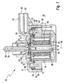
- einen Längsschnitt durch ein Magnetventil;
- Figur 2
- einen Ausschnitt des Magnetventils gemäß Figur 1; und
- Figur 3
- eine perspektivische Ansicht eines Magnetankers des Magnetventils von Figur 1.
In Fig. 1 trägt ein Magnetventil insgesamt das Bezugszeichen
10. Das Magnetventil 10 umfasst ein insgesamt zylindrisches
unteres Gehäuseelement 12 und ein insgesamt zylindrisches
oberes Gehäuseelement 14. Das untere Gehäuseelement 12 weist
einen kreisförmigen Bodenabschnitt 16 und einen an diesen
angeformten, zylindrisch umlaufenden Wandabschnitt 18 auf. Das
untere Gehäuseelement 12 weist ferner einen zum Wandabschnitt
18 in etwa koaxialen, von diesem beabstandeten und radial
außen von diesem angeordneten zylindrisch umlaufenden
Randabschnitt 20 auf, der gemäß Fig. 1 an den oberen Bereich
des unteren Gehäuseelements 12 angeformt ist.
Das obere Gehäuseelement 14 weist einen Deckelabschnitt 22
sowie einen daran angrenzenden, zylindrisch umlaufenden
Wandabschnitt 24 auf. Dessen Innenwand hat in etwa den
gleichen Durchmesser wie die Außenwand des Randabschnitts 20
des unteren Gehäuseelements 12. Das untere Gehäuseelement 12
und das obere Gehäuseelement 14 sind über nicht dargestellte
Rastmittel im Bereich zwischen dem Randabschnitt 20 des
unteren Gehäuseelements 12 und dem Wandabschnitt 24 des oberen
Gehäuseelements 14 schnappend miteinander verbunden. Sie sind
über einen O-Ring 26 gegeneinander abgedichtet, der sich
zwischen dem Randabschnitt 20 des unteren Gehäuseelements 12
und dem Wandabschnitt 24 des oberen Gehäuseelements 14
befindet.
Das untere Gehäuseelement 12 begrenzt mit seinem
Bodenabschnitt 16 sowie mit seinem Randabschnitt 18 einen im
Wesentlichen zylindrisch ausgebildeten Aufnahmeraum 28. In
diesem Aufnahmeraum 28 sind koaxial zu einer zentrischen Achse
30 des Magnetventils 10 weitere Bauteile des Magnetventils 10
angeordnet. In der Mitte ist ein Magnetkern 32 erkennbar, der
von einem Spulenkörper 34 umgeben ist. Der Spulenkörper 34
besteht aus Kunststoff und dient zur Aufnahme einer
Magnetspule 36, die um den Spulenkörper 34 und um den
Magnetkern 32 herum gewickelt ist. Der Magnetkern 32 ist an
seinem in Fig. 1 unteren Ende mit einem rotationssymmetrisch
ausgebildeten Magnettopf 38 verbunden.
Der Magnettopf 38 weist an seinem in Fig. 1 oben dargestellten
Ende einen umlaufenden und radial nach außen weisenden Kragen
39 auf. Dieser stützt sich auf einen O-Ring 40, der den Kragen
39 gegen den Wandabschnitt 18 des unteren Gehäuseelements 12
abdichtet. Zwischen dem Kragen 39 des Magnettopfs 38, dem
Spulenkörper 34 sowie dem Magnetkern 32 einerseits und dem
Deckelabschnitt 22 des oberen Gehäuseelements 14 andererseits
ist eine Schaltkammer 41 ausgebildet. In der Schaltkammer 41
ist ein im Wesentlichen zylindrischer, scheibenförmiger
Magnetanker 42 angeordnet.
Der Magnetanker 42 ist in Fig. 3 einzeln perspektivisch
dargestellt. Er weist eine zentrische Öffnung 43 auf, die von
einer nur in Fig. 1 dargestellten Dichtscheibe 44 überdeckt
ist. Die Dichtscheibe 44 besteht aus einem elastischen
Material und ist auf dem Magnetanker 42 durch einen Haltekäfig
46 gehalten. Der Haltekäfig 46 ist mit dem Magnetanker 42
verschweißt. Der Magnetanker 42 weist auf seiner dem
Deckelabschnitt 22 des oberen Gehäuseelements 14 zugewandten
Seite Vorsprünge 48 auf (siehe auch Fig. 3).
Gemäß Fig. 2 sind die Vorsprünge 48 kegelstumpfförmig
ausgebildet und weisen einen abgerundeten Kopfbereich 50 auf.
Die kegelstumpfförmigen Vorsprünge 48 greifen in der in Fig. 2
dargestellten Endlage des Magnetankers 42 in Ausnehmungen 52
ein, die im Deckelabschnitt 22 des oberen Gehäuseelements 14
ausgebildet sind. Die Ausnehmungen 50 sind komplementär zu den
Vorsprüngen 48 ausgebildet, so dass eine Relativbewegung
zwischen dem Magnetanker 42 und dem Deckelabschnitt 22 des
oberen Gehäuseelements 14 in einer Ebene 53 in der in Fig. 2
dargestellten Endlage des Magnetankers 42 nicht möglich ist.
Die Ebene 53 verläuft senkrecht zur zentrischen Achse 30 des
Magnetventils 10.
Die Fluidwege im Magnetventil 10 verlaufen folgendermaßen
(unter Fluiden werden hier und nachfolgend gasförmige oder
flüssige Strömungsmedien verstanden; vgl. Fig. 1):
Im Magnetventil 10 ist ein erster Fluidkanal 54 ausgebildet,
der sich im Deckelabschnitt 22 des oberen Gehäuseelements 14
von der Schaltkammer 41 bis hin zu einem Anschluss 56
erstreckt. Der Fluidkanal 54 weist an seinem der Schaltkammer
41, zugewandten Ende einen Ventilsitz 58 auf.
Das Magnetventil 10 weist ferner einen Stutzen 60 auf, der
seitlich am oberen Gehäuseelement 14 angeordnet ist. Der
Stutzen 60 umfasst einen Fluidkanalabschnitt 62, der vom
abstehenden Ende 63 des Stutzens 60 bis zu einem zweiten und
zum ersten Fluidkanalabschnitt in etwa in einem rechten Winkel
stehenden Fluidkanalabschnitt 64 verläuft. Der zweite
Fluidkanalabschnitt 64 verläuft parallel zur zentrischen Achse
30 des Magnetventils 10 und mündet in einen Ringraum 66, der
nach radial außen hin vom Randabschnitt 20 des unteren
Gehäuseelements 12 begrenzt ist.
Der Deckelabschnitt 22 des oberen Gehäuseelements 14 weist in
Richtung zum Kragen 39 des Magnettopfs 38 weisende Stege 68
auf. Zwischen den Stegen 68 sind Öffnungen 70 vorhanden, durch
die die Schaltkammer 41 und der Ringraum 66 fluidisch
miteinander verbunden sind.
Im Magnetkern 32 ist eine zentrische Magnetkernbohrung 72
vorgesehen, die sich von der Schaltkammer 41 bis zu einem dem
Bodenabschnitt 16 des unteren Gehäuseelements 12 benachbarten
Ende des Magnetkerns 32 hin erstreckt. Die Magnetkernbohrung
72 weist an ihrem der Schaltkammer 41 zugewandten Ende einen
Ventilsitz 74 auf. Die Magnetkernbohrung 72 steht über den
Aufnahmeraum 28 des unteren Gehäuseelements 12 fluidisch mit
einer Entlüftungsöffnung 76 in Verbindung. Die
Entlüftungsöffnung 76 ist im Wandabschnitt 18 des unteren
Gehäuseelements 12 ausgebildet und verläuft vom Aufnahmeraum
28 durch den Wandabschnitt 18 hindurch und verbindet diesen
mit der Außenatmosphäre 78.
Das Magnetventil 10 funktioniert folgendermaßen:
Das in Fig. 1 dargestellte Magnetventil 10 befindet sich im
geschlossenen Ruhezustand. Dies bedeutet, dass die Magnetspule
36 unbestromt ist. Der Magnetanker 42 befindet sich in der in
Fig. 1 dargestellten Endlage, in der er entweder durch den
zwischen der Magnetkernbohrung 72 und dem Fluidkanal 54
herrschenden Differenzdruck oder über nicht dargestellte
Rückstellmittel in Form einer Feder gehalten wird. Die
Vorsprünge 48 des Magnetankers 42 greifen in die Ausnehmungen
52 im Deckelteil 22. Die Dichtscheibe 44 liegt am Ventilsitz
58 des Fluidkanals 54 an. Dies bedeutet, dass in der in Fig. 1
dargestellten Schaltstellung des Magnetventils 10 der
Fluidkanal 54 und der Fluidkanal 62 durch die Dichtscheibe 44
voneinander getrennt sind.
Um das Magnetventil 10 aus dem Ruhezustand von Fig. 1 in einen
Schaltzustand zu bringen, wird die Magnetspule 36 über nicht
dargestellte elektrische Kontaktmittel bestromt. Durch die
Bestromung wird ein Magnetkreis aufgebaut, der über den
Magnetkern 32, den Magnetanker 42, den Kragen 39 des
Magnettopfs 38 und über den Magnettopf 38 wieder zum
Magnetkern 32 verläuft. Durch den Magnetkreis wird eine
Schließkraft erzeugt, die den Magnetanker 42 zum Magnetkern 32
hin beaufschlagt. Hierdurch bewegt sich der Magnetanker 42 aus
der in Fig. 1 dargestellten Endlage in eine zweite Endlage, in
der der Magnetanker 42 an seinem äußeren Rand auf dem Kragen
39 des Magnettopfs 38 zur Auflage kommt. Dabei wird die
Dichtscheibe 44 dichtend auf den Ventilsitz 74 der
Magnetkernbohrung 72 gedrückt und dabei geringfügig verformt.
In dieser Schaltstellung des Magnetankers besteht zwischen dem
Fluidkanal 54 und über die Schaltkammer 41, die Öffnungen 70
und den Ringraum 66 mit den Fluidkanalabschnitten 64 und 62
eine fluidische Verbindung. Hierdurch kann ein mit dem
Fluidkanalabschnitt 62 verbundener Verbraucher mit Fluid
versorgt werden. Der an den Fluidkanalabschnitt 62
angeschlossene Verbraucher kann bei Anliegen von Vakuum am
Fluidkanal 54 bzw. am Anschluss 56 auch evakuiert werden.
Claims (8)
- Magnetventil (10), insbesondere pneumatisches Vorsteuerventil für Unterdruckdosen, mit einer Magnetspule (36), einem Magnetkern (32), einem stationären Bauelement (22) und einem zwischen zwei Endlagen beweglichen Bauelement (42), dadurch gekennzeichnet, dass das eine Bauelement (22, 42) mindestens einen Vorsprung (48) aufweist und dass das andere Bauelement eine zum Vorsprung (48) komplementäre Ausnehmung (52) aufweist, wobei die Ausnehmung (52) und der Vorsprung (48) in einer Endlage des beweglichen Bauelements (42) zusammenwirken und in der anderen Endlage voneinander beabstandet sind.
- Magnetventil (10) nach Anspruch 1, dadurch gekennzeichnet, dass das bewegliche Bauelement (42) einen Magnetanker umfasst.
- Magnetventil (10) nach einem der vorhergehenden Ansprüche, dadurch gekennzeichnet, dass das stationäre Bauelement (22) eine Abdeckung oder ein Gehäuseteil des Magnetventils (10) umfasst.
- Magnetventil (10) nach einem der vorhergehenden Ansprüche, dadurch gekennzeichnet, dass der Vorsprung (48) kegelstumpfförmig und die komplementäre Ausnehmung (52) trichterförmig ausgebildet ist.
- Magnetventil (10) nach einem der vorhergehenden Ansprüche, dadurch gekennzeichnet, dass der Vorsprung (48) als Kugelabschnitt und die komplementäre Ausnehmung (52) sphärisch ausgebildet ist.
- Magnetventil (10) nach einem der vorhergehenden Ansprüche, dadurch gekennzeichnet, dass der Vorsprung (48) zumindest abschnittsweise als Torus und die komplementäre Ausnehmung (52) zumindest abschnittsweise rillenförmig ausgebildet ist.
- Magnetventil (10) nach einem der vorhergehenden Ansprüche, dadurch gekennzeichnet, dass ein Ventilkörper vorgesehen ist, der wenigstens bereichsweise den Vorsprung umfasst und/oder bildet.
- Magnetventil (10) nach einem der vorhergehenden Ansprüche, dadurch gekennzeichnet, dass der Magnetkern (32) mindestens auf der dem Magnetanker (42) zugewandten Seite und/oder der Magnetanker (42) auf der dem Magnetkern (32) zugewandten Seite eine nicht magnetisierbare Oberflächenschicht aufweist.
Applications Claiming Priority (2)
| Application Number | Priority Date | Filing Date | Title |
|---|---|---|---|
| DE10220719 | 2002-05-10 | ||
| DE10220719A DE10220719A1 (de) | 2002-05-10 | 2002-05-10 | Magnetventil |
Publications (1)
| Publication Number | Publication Date |
|---|---|
| EP1361383A1 true EP1361383A1 (de) | 2003-11-12 |
Family
ID=29225121
Family Applications (1)
| Application Number | Title | Priority Date | Filing Date |
|---|---|---|---|
| EP02025671A Withdrawn EP1361383A1 (de) | 2002-05-10 | 2002-11-20 | Magnetventil |
Country Status (2)
| Country | Link |
|---|---|
| EP (1) | EP1361383A1 (de) |
| DE (1) | DE10220719A1 (de) |
Cited By (2)
| Publication number | Priority date | Publication date | Assignee | Title |
|---|---|---|---|---|
| DE102004033695A1 (de) * | 2004-07-13 | 2006-02-16 | Steuerungstechnik Staiger Gmbh & Co. Produktions-Vertriebs-Kg | Ventil |
| WO2015058914A1 (de) * | 2013-10-24 | 2015-04-30 | Pierburg Gmbh | Aktor für ventile in verbrennungskraftmaschinen |
Citations (5)
| Publication number | Priority date | Publication date | Assignee | Title |
|---|---|---|---|---|
| FR2129734A5 (de) * | 1971-03-16 | 1972-10-27 | Heimann Georg | |
| DE3015522A1 (de) * | 1980-04-23 | 1981-10-29 | Wabco Fahrzeugbremsen Gmbh, 3000 Hannover | Magnetventil mit membrananker |
| US4567910A (en) * | 1984-11-26 | 1986-02-04 | Lectron Products, Inc. | Vacuum regulator |
| EP0549490A1 (de) * | 1991-12-23 | 1993-06-30 | Eaton S.A.M. | Elektromagnetventil mit einem flachen beweglichen Kolben |
| US6382587B1 (en) * | 1999-05-17 | 2002-05-07 | Bld Products, Ltd. | Fluid control valve |
Family Cites Families (3)
| Publication number | Priority date | Publication date | Assignee | Title |
|---|---|---|---|---|
| CA1192174A (en) * | 1981-10-14 | 1985-08-20 | William L. Sheppard | Magnetic air valve |
| US4745386A (en) * | 1986-06-27 | 1988-05-17 | Smith Corona Corporation | Solenoid device |
| DE3829676A1 (de) * | 1988-09-01 | 1990-03-15 | Olympia Aeg | Tauchankermagnet, sowie dessen verwendung als druckhammer in einer druckhammervorrichtung |
-
2002
- 2002-05-10 DE DE10220719A patent/DE10220719A1/de not_active Ceased
- 2002-11-20 EP EP02025671A patent/EP1361383A1/de not_active Withdrawn
Patent Citations (5)
| Publication number | Priority date | Publication date | Assignee | Title |
|---|---|---|---|---|
| FR2129734A5 (de) * | 1971-03-16 | 1972-10-27 | Heimann Georg | |
| DE3015522A1 (de) * | 1980-04-23 | 1981-10-29 | Wabco Fahrzeugbremsen Gmbh, 3000 Hannover | Magnetventil mit membrananker |
| US4567910A (en) * | 1984-11-26 | 1986-02-04 | Lectron Products, Inc. | Vacuum regulator |
| EP0549490A1 (de) * | 1991-12-23 | 1993-06-30 | Eaton S.A.M. | Elektromagnetventil mit einem flachen beweglichen Kolben |
| US6382587B1 (en) * | 1999-05-17 | 2002-05-07 | Bld Products, Ltd. | Fluid control valve |
Cited By (4)
| Publication number | Priority date | Publication date | Assignee | Title |
|---|---|---|---|---|
| DE102004033695A1 (de) * | 2004-07-13 | 2006-02-16 | Steuerungstechnik Staiger Gmbh & Co. Produktions-Vertriebs-Kg | Ventil |
| DE102004033695B4 (de) * | 2004-07-13 | 2008-06-12 | Steuerungstechnik Staiger Gmbh & Co. Produktions-Vertriebs-Kg | Ventil |
| WO2015058914A1 (de) * | 2013-10-24 | 2015-04-30 | Pierburg Gmbh | Aktor für ventile in verbrennungskraftmaschinen |
| US9970337B2 (en) | 2013-10-24 | 2018-05-15 | Pierburg Gmbh | Actuator for valves in internal combustion engines |
Also Published As
| Publication number | Publication date |
|---|---|
| DE10220719A1 (de) | 2003-11-27 |
Similar Documents
| Publication | Publication Date | Title |
|---|---|---|
| EP1004066B2 (de) | Elektromagnetisches druckregelventil | |
| EP1315900B1 (de) | Brennstoffeinspritzventil | |
| EP0195261A2 (de) | Magnetventil, insbesondere Kraftstoffmengensteuerventil | |
| EP1589545A2 (de) | Magnetantrieb für ein Ventil | |
| EP2307699B1 (de) | Magnetventil für einen kraftstoff-injektor sowie kraftstoff-injektor | |
| WO2000017551A1 (de) | Elektromagnetisch betätigbares, hydraulisches proportionalventil | |
| EP3559437B1 (de) | Ventil zum zumessen eines fluids | |
| WO2018007068A1 (de) | Ventil zum eindüsen von gasförmigem kraftstoff | |
| DE10063710A1 (de) | Ventileinrichtung | |
| DE19915210A1 (de) | Brennstoffeinspritzventil | |
| DE19510646A1 (de) | Elektromagnetisch betätigbares Druckschaltventil | |
| WO2002075143A1 (de) | Magnetventil | |
| DE4422972A1 (de) | Mikroventil mit elektromagnetischem Antrieb | |
| EP0793004B1 (de) | Elektromagnetische Ventilbetätigung | |
| EP0710790A1 (de) | Magnetventil und dessen Verwendung | |
| EP1361383A1 (de) | Magnetventil | |
| DE102004015661B4 (de) | Elektropneumatisches Ventil, insbesondere Vorsteuerventil für ein pneumatisches Wegeventil | |
| DE10130239A1 (de) | Brennstoffeinspritzventil und Verfahren zu dessen Einstellung | |
| WO2021115679A1 (de) | Elektromagnetventil | |
| EP1361358A1 (de) | Magnetventil, insbesondere Mengensteuerventil für Kraftstoffsysteme von Brennkraftmaschinen | |
| WO2020020836A1 (de) | Ventil | |
| DE19836865C1 (de) | Magnetventil | |
| WO2023030787A1 (de) | Magnetventil sowie wasserstofftanksystem mit magnetventil | |
| DE102004021528B4 (de) | Elektropneumatisches Sitzventil mit einem nach Art des Hubankersystems ausgebildeten elektromagnetischen Antrieb | |
| EP0926412B1 (de) | Elektromagnetantrieb |
Legal Events
| Date | Code | Title | Description |
|---|---|---|---|
| PUAI | Public reference made under article 153(3) epc to a published international application that has entered the european phase |
Free format text: ORIGINAL CODE: 0009012 |
|
| AK | Designated contracting states |
Kind code of ref document: A1 Designated state(s): AT BE BG CH CY CZ DE DK EE ES FI FR GB GR IE IT LI LU MC NL PT SE SK TR |
|
| AX | Request for extension of the european patent |
Extension state: AL LT LV MK RO SI |
|
| 17P | Request for examination filed |
Effective date: 20040512 |
|
| 17Q | First examination report despatched |
Effective date: 20040607 |
|
| AKX | Designation fees paid |
Designated state(s): DE FR GB IT SE |
|
| STAA | Information on the status of an ep patent application or granted ep patent |
Free format text: STATUS: THE APPLICATION IS DEEMED TO BE WITHDRAWN |
|
| 18D | Application deemed to be withdrawn |
Effective date: 20041019 |