EP1361070B1 - Multi-resolution printing method and printing device - Google Patents
Multi-resolution printing method and printing device Download PDFInfo
- Publication number
- EP1361070B1 EP1361070B1 EP02100468A EP02100468A EP1361070B1 EP 1361070 B1 EP1361070 B1 EP 1361070B1 EP 02100468 A EP02100468 A EP 02100468A EP 02100468 A EP02100468 A EP 02100468A EP 1361070 B1 EP1361070 B1 EP 1361070B1
- Authority
- EP
- European Patent Office
- Prior art keywords
- printing
- printhead
- nozzles
- velocity
- ref
- Prior art date
- Legal status (The legal status is an assumption and is not a legal conclusion. Google has not performed a legal analysis and makes no representation as to the accuracy of the status listed.)
- Expired - Lifetime
Links
Images


Classifications
-
- B—PERFORMING OPERATIONS; TRANSPORTING
- B41—PRINTING; LINING MACHINES; TYPEWRITERS; STAMPS
- B41J—TYPEWRITERS; SELECTIVE PRINTING MECHANISMS, i.e. MECHANISMS PRINTING OTHERWISE THAN FROM A FORME; CORRECTION OF TYPOGRAPHICAL ERRORS
- B41J2/00—Typewriters or selective printing mechanisms characterised by the printing or marking process for which they are designed
- B41J2/485—Typewriters or selective printing mechanisms characterised by the printing or marking process for which they are designed characterised by the process of building-up characters or image elements applicable to two or more kinds of printing or marking processes
- B41J2/505—Typewriters or selective printing mechanisms characterised by the printing or marking process for which they are designed characterised by the process of building-up characters or image elements applicable to two or more kinds of printing or marking processes from an assembly of identical printing elements
- B41J2/5056—Typewriters or selective printing mechanisms characterised by the printing or marking process for which they are designed characterised by the process of building-up characters or image elements applicable to two or more kinds of printing or marking processes from an assembly of identical printing elements using dot arrays providing selective dot disposition modes, e.g. different dot densities for high speed and high-quality printing, array line selections for multi-pass printing, or dot shifts for character inclination
Definitions
- the present invention relates to apparatus and methods for printing and in particular to drop-on-demand (DOD) inkjet printing methods and apparatus.
- DOD drop-on-demand
- thermal inkjet When DOD inkjet is considered, two main groups can be discerned: thermal inkjet and piezo inkjet.
- thermal inkjet technology tiny resistors rapidly heat a thin layer of liquid ink.
- the heated ink causes a vapour bubble to be formed, expelling or ejecting drops of ink through nozzles and placing them precisely on a surface to form text or images.
- thermal inkjet technology water-based inks are used.
- Piezoelectric printing technology commonly called piezo - pumps ink through nozzles using pressure, like a squirt gun.
- a piezo crystal used as a very precise pump places ink onto the printing medium.
- a wide range of ink formulations solvent, water, UV may be used.
- nozzles are located close to each other. Different nozzles next to each other suffer from cross-talk, both thermal cross-talk and mechanical cross-talk.
- the most severe form of cross-talk is mechanical cross-talk generated by using a common wall or shared wall between two nozzles, as explained hereinafter.
- a typical concept as described in US-4887100, WO 96/10488, WO 97/04963 and WO 99/12738, uses so called shared walls.
- the pressure chambers containing the ink are next to each other, while their dividing walls are the actuators.
- WO 96/10488 is described that the nozzles are divided in three interlaced groups (A, B, C). Neighbouring nozzles are fired in a sequence ABC. Two solutions are possible to print dots on a straight line.
- a first solution uses a complete nozzle array under a certain angle. By doing this, the resolution is increased, and by using the right fast scan speed, dots fired in a sequence A, B, C are on a straight line.
- a drawback of this concept is that, once the firing frequency is defined, only one fast scan speed can be used to print ABC dots on a straight line, as explained hereinafter. In the fast scan direction, the head will e.g. print each 1/360-inch.
- Fig. 1 shows a piezo printhead 10 according to the prior art, having nozzles 12 which are divided into three sets, called a set of A nozzles, a set of B nozzles and a set of C nozzles, each set intended to be fired during different firing cycles.
- the different sets of nozzles are staggered with respect to each other over a stagger distance D1 in the fast scan direction.
- the nozzles are divided in groups G of three, every first nozzle is part of the set of A nozzles, every second nozzle is part of the set of B nozzles and every third nozzle is part of the set of C nozzles. All nozzles in one set A, B, C are positioned on a straight line in the slow scan direction S, which lines are located at the stagger distance D1 with respect to each other in the fast scan direction F.
- the firing frequency is 12.4 kHz, meaning that every set A, B, C of nozzles can be fired every 80.65 ps
- the nozzles 12 are fired in an ABC sequence, with the A nozzles at the leading edge of the printhead 10 in the fast scan direction F.
- the set of B nozzles fires 26.88 ⁇ s after the set of A nozzles
- the set of C nozzles fires 53.76 ⁇ s after the set of A nozzles.
- 80.65 ps the set of A nozzles fires again.
- the printhead speed should theoretically double to 1.750 m/s.
- the delays for firing B and C need to be shorter to make sure that dots are printed on the same line.
- Nozzle set B has to be fired 13.44 ⁇ s after nozzle set A, and nozzle set C 26.88 ⁇ s after nozzle set A.
- EP 677 390 a method for printing graphical images is disclosed lowering visibility of nozzle imperfections by using multiple printing passes.
- the above objects are achieved by a method of printing an image onto a printing medium using a printing system with an elongate printhead having an array of marking elements (A, B, C, A, B, C) comprising at least one group (G) of marking elements (A, B, C), the marking elements (A, B, C) of one group are staggered with respect to each other over a stagger distance (D1) in a fast scan direction to form a plurality of rows (6,7,8) of marking elements, the direction of the rows forming a longitudinal axis of the printhead, the printhead being intended to be driven with a reference velocity (F ref ) which is equal to the stagger distance (D10 multiplied by a reference firing frequency (F ref ), and being driven in the fast scan direction (F) to print marks on the printing medium along one swath of print in one pass, and the printing medium and the printhead being movable relative to each other in a slow scan direction (S) to print further swaths, and the printing system
- the image may be formed of a superposition of monochromatic subimages (called separations) in which case the repeating of the printing passes relates to each monochromatic sub-image.
- the reference velocity (V ref ) is equal to the stagger distance (D1) multiplied by a reference firing frequency (F ref ).
- One marking element of a group is able to be fired at each reference firing frequency pulse (whether it fires depends upon the image to be printed).
- the marking elements of the print head are intended to be fired according to a reference firing order to print an image with a first resolution.
- the method may include delaying printing data representing the image supplied to some of the marking elements with respect to the printing data supplied to other marking elements.
- printing should be construed broadly. It relates to forming markings whether by ink or other materials or methods onto a printing substrate.
- Various printing methods which may be used with the present invention are described in the book “Principles of non-impact printing", J. L. Johnson, Palatino Press, Irvine, 1998, e.g. thermal transfer printing, thermal dye transfer printing, deflected ink jet printing, ion projection printing, field control printing, impulse ink jet printing, drop-on-demand ink jet printing, continuous ink jet printing.
- Non-contact printing methods are particularly preferred.
- the present invention is not limited thereto. Any form of printing including dots or droplets on a substrate is included within the scope of the present invention, e.g.
- the printing may be carried out at room temperature or at elevated temperature, e.g. to print a hot-melt adhesive the printhead may be heated above the melting temperature.
- the term "ink” should also be interpreted broadly including not only conventional inks but also solid materials such as polymers which may be printed in solution or by lowering their viscosity at high temperatures as well as materials which provide some characteristic to a printed substrate such as information defined by a structure on the surface of the printing substrate, water repellence, or binding molecules such as DNA which are spotted onto micro-arrays.
- solvents both water and organic solvents may be used.
- Inks as used with the present invention may include a variety of additives such as ant-oxidants, pigments and cross-linking agents.
- ink jet printing in which a printhead traverses with respect to a printing medium in a first direction (fast scan direction) while the print medium indexes forwards relative to the printhead in a direction perpendicular to this (slow scan direction).
- the present invention is particularly useful for printing heads having a plurality of marking elements and with which firing of marking elements is prevented by the system or would cause a printing defect.
- This type of head can be an ink jet printing head. If there are shared walls between the nozzles of the head it is not possible to fire two adjacent at the same time. This is an extreme example of what in general might be called crosstalk between adjacent marking elements.
- Such crosstalk may be caused by thermal (e.g. spread of heat energy and therefore change of temperature), mechanical (e.g. shock waves propgating through the head), fluid (e.g. pressure pulses in the ink supply) or electrical (e.g. current to flow through one heating element leaks to an adjacent heating element, an electric field generated by applying a voltage to one electrode of a first marking element may generate an electric field at an electrode of an adjacent marking element) effects for example.
- thermal e.g. spread of heat energy and therefore change of temperature
- mechanical e.g. shock waves propgating through the head
- fluid e.g. pressure pulses in the ink supply
- electrical e.g. current to flow through one heating element leaks to an adjacent heating element, an electric field generated by applying a voltage to one electrode of a first marking element may generate an electric field at an electrode of an adjacent marking element
- effects may reduce or increase, for example, ink drop size or cause some other type of printing defect.
- This defect may be that at least one of the adjacent marking elements does not print at all (which is the case for ink jet printheads with common walls), or that at least one of them prints with a defect.
- the size or intensity of the mark is at least 5% more or less than the intended mark size or density if both marking elements for are actuated at the same time.
- the printing system prevents simultaneous firing of adjacent marking elements even if such a firing could be made. In a system designed not to print with adjacent marking elements simultaneously, any such simultaneous firing is a printing defect in accordance with the present invention and the attached claims. With respect to any of the embodiments of the invention below the printhead and the printing system may be of the above type, i.e. that simultaneous firing of adjacent marking elements is prevented.
- the speed in the fast scan direction is set at a particular velocity or changed from a reference velocity with which the printhead is intended to be driven (in case of printheads with staggered marking elements) to a particular velocity, while preferably keeping the firing frequency of the sets of nozzles unchanged. This is done in order to be able to print, with a printhead of a certain type, which is intended to print images with a certain resolution, images with other resolutions.
- a printhead 10 used according to the first embodiment has a number of wets of marking elements, e.g. three sets of marking elements or nozzles 12: a set of A-nozzles, a set of B-nozzles and a set of C-nozzles. This means that there are three nozzles 12 in one group G, as represented in Fig. 1. Each of the sets of nozzles form a row 6, 7, 8, the direction of which forms a longitudinal axis of the printhead 10.
- the reference firing frequency F ref for this type of head is 12.4 kHz, meaning that every set A, B, C of nozzles can be fired every 80.65 ⁇ s
- the nozzles 12 are fired in an ABC sequence, with the A nozzles at the leading edge of the printhead 10 in the fast scan direction F.
- the fast scan speed must be double the reference velocity (i.e. 1.75 m/s) and the printhead has to pass 6 times over the same swath.
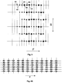
- a nozzles eject drops on locations 14 on a straight line 16 in the slow scan direction S. Drops ejectable during the first pass of the printhead 10 over the print medium (because the nozzles are firable), are indicated in Fig. 2 by black circles. Whether or not they are fired depends on the image to be printed. Locations above which nozzles are located at certain moments in time during the first pass of printhead 10 over the print medium, but where no drops are printed because the respective nozzles are not firable there, are indicated by means of white circles in Fig. 2.
- the printhead 10 is moved, with a velocity V which equals for example twice the reference velocity V ref , and which is thus 1.75 m/s for the example given, during a time which equals T ref / 3.
- the set of A nozzles eject drops on locations 36 on a straight line 38 in the slow scan direction S, where necessary according to the image to be printed.
- the set of B nozzles is located at locations 40 at a distance of 23.52 ⁇ m behind the set of A nozzles.
- the printhead 10 is moved over a distance of 47.04 ⁇ m in the fast scan direction F.
- the set of B nozzles eject drops on locations 42 on a straight line 43 in the slow scan direction S, where necessary according to the image to be printed.
- the head 10 Before firing the set of C nozzles, the head 10 is moved over a distance of 47.04 ⁇ m in the fast scan direction F. During the first cycle of the second pass, the set of C nozzles eject drops on locations 54, where necessary according to the image to be printed.
- dots 44 written with the A nozzles during the second pass of the printhead 10 over a swath are written right in the middle between two dots 14, 36 written with the A nozzles during the first pass, in reality those locations will generally be different.
- Fig. 3 during a first pass, dots are written on locations 60 indicated with circles; during a second pass, dots are written on locations 62 indicated with squares; during a third pass, dots are written on locations 64 indicated with triangles; during a fourth pass, dots are written on locations 66 indicated with pentagons; during a fifth pass, dots are written on locations 68 indicated with stars; and during a sixth pass, dots are written on locations 70 indicated with hexagons.
- Fig. 3 after six passes, all intermediate locations are filled out (if needed according to the image content), and the desired image is written in a higher resolution than the resolution the printhead was intended for.
- this shift is done over a distance which is a multiple of the number of nozzles in one group, so that A nozzles always print on the same line in the fast scan direction.
- Another possibility is to shift the head over a number of nozzles which is not a multiple of the number of nozzles in a group, and fill out the image in a number of passes which is not a multiple of the number of nozzles in a group.
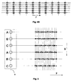
- Fig. 4B In the example given, there are 3 nozzles in a group, and 5 passes are needed to completely fill out the image.
- the locations where nozzles C should print C4, C5, C6) are already printed during previous passes. Therefore, during passes 4, 5 and 6 the set of C nozzles is not fired.
- the printhead was traversed in the fastscan direction at a speed higher than the reference velocity.
- the present invention also includes traversing the head at a velocity slower than the reference velocity.
- Fig. 5 an example is given of a printhead without nozzle stagger, where there are 3 nozzles A, B, C in a group. Shared walls (not represented) between the nozzles prevent neighbouring nozzles from firing at the same moment. Dots indicated by circles are printed (or not, depending on the image content; but the nozzle is firable there) during a first pass, dots represented by squares are printed (or not, depending on the image content) during a second pass, and dots represented by stars are printed (or not, depending on the image content) during a third pass. As can be seen from Fig. 5, after 3 passes the complete image is printed.
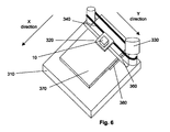
- Fig. 6 is a highly schematic general perspective view of an inkjet printer 200 which can be used with the present invention.
- the printer 200 includes a base 310, a carriage assembly 320, a step motor 330, a drive belt 340 driven by the step motor 330, and a guide rail assembly 360 for the carriage assembly 320.
- Mounted on the carriage assembly 320 is a printhead 10 that has a plurality of nozzles.
- the printhead 10 may also include one or more ink cartridges or any suitable ink supply system.
- a sheet of paper 370 is fed in the slow scan direction over a support 380 by a feed mechanism (not shown).
- the carriage assembly 320 is moved along the guide rail assembly 360 by the action of the drive belt 340 driven by the step motor 330 in the fast scanning direction.
- Fig. 7 is a block diagram of the electronic control system of a printer 200, which is one example of a control system for use with a printhead 10.
- the printer 200 includes a buffer memory 400 for receiving a print file in the form of signals from a host computer 300, an image buffer 420 for storing printing data, and a printer controller 600 that controls the overall operation of the printer 200.
- a fast scan driver 620 for a carriage assembly drive motor 660
- a slow scan driver 640 for a paper feed drive motor 680
- a head driver 440 for the printhead 10.
- there is a data store 700 for storing parameters for controlling the printing operation.
- Host computer 300 may be any suitable programmable computing device such as personal computer with a Pentium III microprocessor supplied by Intel Corp. USA, for instance, with memory and a graphical interface such as Windows 98 as supplied by Microsoft Corp. USA.
- the printer controller 600 may include a computing device, e.g. microprocessor, for instance it may be a microcontroller.
- a programmable printer controller for instance a programmable digital logic element such as a Programmable Array Logic (PAL), a Programmable Logic Array, a Programmable Gate Array, especially a Field Programmable Gate Array (FPGA).
- PAL Programmable Array Logic
- FPGA Field Programmable Gate Array
- the user of printer 200 can optionally set values into the data store 700 so as to modify the operation of the printhead 10.
- the user can for instance set values into the data store 700 by means of a menu console 460 on the printer 200.
- these parameters may be set into the data store 700 from host computer 300, e.g. by manual entry via a keyboard.
- a printer driver (not shown) of the host computer 300 determines the various parameters that define the printing operations and transfers these to the printer controller 600 for writing into the data store 700, e.g. the resolution.
- the printer controller 600 controls the operation of printhead 10 in accordance with settable parameters stored in data store 700.
- controller 600 is adapted for a dot matrix printer for printing an image on a printing medium, the control unit comprising software or hardware means for controlling printing of the image in multiple passes whereby in each pass parallel lines are printed at a non-zero angle with respect to the longitudinal axis of the printhead and also at a non-zero angle with respect to the fast scan direction, which series of parallel lines do not form a complete part of the image.
- the control unit furthermore comprises software or hardware means for setting the resolution.
- the controller may be used for independently setting the resolution.
- the printhead has an array of marker elements under the control of the controller.
- the controller may be adapted so that for a specific resolution the speed of the head in the fast scan direction is controlled. Resolutions may be selected by the user.
- the printing data is broken down into the individual colour components to obtain image data in the form of a bit map for each colour component which is stored in the receive buffer memory 300.
- the head driver 440 reads out the colour component image data from the image buffer memory 520 in accordance with a specified resolution to drive the speed and the array(s) of nozzles on the printhead 10 to achieve the required resolution.
- the controller 600 may be programmable, e.g. it may include a microprocessor or an FPGA.
- a printer may be programmed to provide different resolutions.
- the basic model of the printer may provide selection of one resolution only.
- An upgrade in the form of a program to download into the microprocessor or FPGA of the controller 600 may provide additional selection functionality, e.g. a plurality of resolutions.
- the present invention could be used with a computer program product which provides the functionality of any of the methods according to the present invention when executed on a computing device.
- a data carrier such as a CD-ROM or a diskette which stores the computer product in a machine readable form and which executes at least one of the methods of the invention when executed on a computing device could be included.
- a data carrier such as a CD-ROM or a diskette which stores the computer product in a machine readable form and which executes at least one of the methods of the invention when executed on a computing device could be included.
- Such software is often offered on the
- the data store 700 may comprise any suitable device for storing digital data as known to the skilled person, e.g. a register or set of registers, a memory device such as RAM, EPROM or solid state memory.
- the preparation for the printing file to carry out the above mentioned printed embodiments may be prepared by the host computer 300 and the printer 200 simply prints in accordance with this file as a slave device of the host computer 300.
- the present invention could be adapted so that the printing schemes of the present invention are implemented in software on a host computer and printed on a printer which carries out the instructions from the host computer without amendment.
- a computer program product could be included which provides the functionality of any of the methods according to the present invention when executed on a computing device which is associated with a printhead, that is the printhead and the programmable computing device may be included with the printer or the programmable device may be a computer or computer system, e.g. a Local Area Network connected to a printer.
- the printer may be a network printer.
- a data carrier such as a CD-ROM or a diskette could be included which stores the computer product in a machine readable form and which can execute at least one of the methods of the invention when the program stored on the data carrier is executed on a computing device.
- the computing device may include a personal computer or a work station.
- such software is often offered on the Internet or a company Intranet for download, hence the printing computer product could be transmitted over a local or wide area network.
Landscapes
- Engineering & Computer Science (AREA)
- Quality & Reliability (AREA)
- Ink Jet (AREA)
Priority Applications (4)
| Application Number | Priority Date | Filing Date | Title |
|---|---|---|---|
| EP02100468A EP1361070B1 (en) | 2002-05-08 | 2002-05-08 | Multi-resolution printing method and printing device |
| DE2002609636 DE60209636T2 (de) | 2002-05-08 | 2002-05-08 | Druckverfahren mit mehreren Auslösungen und Druckvorrichtung |
| US10/411,476 US6902247B2 (en) | 2002-05-08 | 2003-04-10 | Multi-resolution printing method and printing device |
| JP2003126322A JP2003326688A (ja) | 2002-05-08 | 2003-05-01 | 多解像度プリンテイング方法とプリンテイング装置 |
Applications Claiming Priority (1)
| Application Number | Priority Date | Filing Date | Title |
|---|---|---|---|
| EP02100468A EP1361070B1 (en) | 2002-05-08 | 2002-05-08 | Multi-resolution printing method and printing device |
Publications (2)
| Publication Number | Publication Date |
|---|---|
| EP1361070A1 EP1361070A1 (en) | 2003-11-12 |
| EP1361070B1 true EP1361070B1 (en) | 2006-03-08 |
Family
ID=29225715
Family Applications (1)
| Application Number | Title | Priority Date | Filing Date |
|---|---|---|---|
| EP02100468A Expired - Lifetime EP1361070B1 (en) | 2002-05-08 | 2002-05-08 | Multi-resolution printing method and printing device |
Country Status (3)
| Country | Link |
|---|---|
| EP (1) | EP1361070B1 (enExample) |
| JP (1) | JP2003326688A (enExample) |
| DE (1) | DE60209636T2 (enExample) |
Families Citing this family (5)
| Publication number | Priority date | Publication date | Assignee | Title |
|---|---|---|---|---|
| US6902247B2 (en) | 2002-05-08 | 2005-06-07 | Agfa-Gevaert | Multi-resolution printing method and printing device |
| JP4479732B2 (ja) * | 2007-01-30 | 2010-06-09 | ブラザー工業株式会社 | インクジェット記録装置 |
| JP2008252413A (ja) * | 2007-03-30 | 2008-10-16 | Nec Corp | 優先制御システム、優先制御装置及びそれらに用いる優先制御方法並びにそのプログラム |
| CN102837521B (zh) * | 2012-07-06 | 2017-05-17 | 江苏汉印机电科技发展有限公司 | 多喷嘴喷头高精度喷印循环点火方法 |
| NL2020081B1 (en) | 2017-12-13 | 2019-06-21 | Xeikon Mfg Nv | Digital printing apparatus and method |
Citations (1)
| Publication number | Priority date | Publication date | Assignee | Title |
|---|---|---|---|---|
| EP0677390A1 (en) * | 1994-04-14 | 1995-10-18 | OLIVETTI-CANON INDUSTRIALE S.p.A. | Method of improving the printing of graphic images and related ink jet dot matrix printing apparatus |
Family Cites Families (5)
| Publication number | Priority date | Publication date | Assignee | Title |
|---|---|---|---|---|
| US4879568A (en) | 1987-01-10 | 1989-11-07 | Am International, Inc. | Droplet deposition apparatus |
| US5512922A (en) | 1989-10-10 | 1996-04-30 | Xaar Limited | Method of multi-tone printing |
| US5975679A (en) * | 1993-10-29 | 1999-11-02 | Hewlett-Packard Company | Dot alignment in mixed resolution printer |
| GB9515337D0 (en) | 1995-07-26 | 1995-09-20 | Xaar Ltd | Pulsed droplet deposition apparatus |
| GB9719071D0 (en) | 1997-09-08 | 1997-11-12 | Xaar Ltd | Drop-on-demand multi-tone printing |
-
2002
- 2002-05-08 DE DE2002609636 patent/DE60209636T2/de not_active Expired - Lifetime
- 2002-05-08 EP EP02100468A patent/EP1361070B1/en not_active Expired - Lifetime
-
2003
- 2003-05-01 JP JP2003126322A patent/JP2003326688A/ja active Pending
Patent Citations (1)
| Publication number | Priority date | Publication date | Assignee | Title |
|---|---|---|---|---|
| EP0677390A1 (en) * | 1994-04-14 | 1995-10-18 | OLIVETTI-CANON INDUSTRIALE S.p.A. | Method of improving the printing of graphic images and related ink jet dot matrix printing apparatus |
Also Published As
| Publication number | Publication date |
|---|---|
| JP2003326688A (ja) | 2003-11-19 |
| EP1361070A1 (en) | 2003-11-12 |
| DE60209636T2 (de) | 2006-12-28 |
| DE60209636D1 (de) | 2006-05-04 |
Similar Documents
| Publication | Publication Date | Title |
|---|---|---|
| US6464316B1 (en) | Bi-directional printmode for improved edge quality | |
| EP1176021B1 (en) | Printing system that utilizes print masks with resolutions that are non-integral multiples of each other | |
| EP1052097B1 (en) | A liquid jetting apparatus | |
| JP2944805B2 (ja) | インクジェットプリンタ及び印字方法 | |
| EP0497614B1 (en) | Method for high-speed interlaced printing along the axis of print head scanning | |
| US6669330B2 (en) | Staggered multi-phase firing of nozzle heads for a printer | |
| US6679583B2 (en) | Fast mutually interstitial printing | |
| JPH07276794A (ja) | 図形像のプリンティング方法及びそのプリンティング装置 | |
| EP1361070B1 (en) | Multi-resolution printing method and printing device | |
| JP2008155377A (ja) | インクジェットヘッド | |
| US6682172B2 (en) | Method and apparatus for maintaining colour sequence when printing | |
| US6902247B2 (en) | Multi-resolution printing method and printing device | |
| JPH06135013A (ja) | 多色インクを使用したインクジェット記録方法 | |
| EP1361068A1 (en) | Staggered multi-phase firing of nozzle heads for a printer | |
| US7025437B2 (en) | Printing methods and apparatus for mutually interstitial printing and optional interlacing | |
| US6604812B2 (en) | Print direction dependent firing frequency for improved edge quality | |
| EP1308296B1 (en) | Method and apparatus for maintaining colour sequence when printing | |
| US6786569B2 (en) | Printing methods and apparatus for reducing banding due to paper transport | |
| EP1642723B1 (en) | Printing methods and apparatus for reducing banding due to paper transport | |
| EP1308293B1 (en) | Printing methods and apparatus for mutually interstitial printing and optional interlacing | |
| EP1308881A1 (en) | Fast mutually interstitial printing | |
| EP0897804A2 (en) | Liquid ink printhead | |
| EP1621353B1 (en) | Printing apparatus for maintaining colour sequence when printing |
Legal Events
| Date | Code | Title | Description |
|---|---|---|---|
| PUAI | Public reference made under article 153(3) epc to a published international application that has entered the european phase |
Free format text: ORIGINAL CODE: 0009012 |
|
| AK | Designated contracting states |
Kind code of ref document: A1 Designated state(s): AT BE CH CY DE DK ES FI FR GB GR IE IT LI LU MC NL PT SE TR |
|
| AX | Request for extension of the european patent |
Extension state: AL LT LV MK RO SI |
|
| 17P | Request for examination filed |
Effective date: 20040512 |
|
| AKX | Designation fees paid |
Designated state(s): DE FR GB |
|
| 17Q | First examination report despatched |
Effective date: 20040826 |
|
| GRAP | Despatch of communication of intention to grant a patent |
Free format text: ORIGINAL CODE: EPIDOSNIGR1 |
|
| GRAS | Grant fee paid |
Free format text: ORIGINAL CODE: EPIDOSNIGR3 |
|
| GRAA | (expected) grant |
Free format text: ORIGINAL CODE: 0009210 |
|
| AK | Designated contracting states |
Kind code of ref document: B1 Designated state(s): DE FR GB |
|
| REG | Reference to a national code |
Ref country code: GB Ref legal event code: FG4D |
|
| REF | Corresponds to: |
Ref document number: 60209636 Country of ref document: DE Date of ref document: 20060504 Kind code of ref document: P |
|
| ET | Fr: translation filed | ||
| PLBE | No opposition filed within time limit |
Free format text: ORIGINAL CODE: 0009261 |
|
| STAA | Information on the status of an ep patent application or granted ep patent |
Free format text: STATUS: NO OPPOSITION FILED WITHIN TIME LIMIT |
|
| 26N | No opposition filed |
Effective date: 20061211 |
|
| REG | Reference to a national code |
Ref country code: GB Ref legal event code: 732E |
|
| REG | Reference to a national code |
Ref country code: FR Ref legal event code: TP |
|
| REG | Reference to a national code |
Ref country code: FR Ref legal event code: PLFP Year of fee payment: 14 |
|
| PGFP | Annual fee paid to national office [announced via postgrant information from national office to epo] |
Ref country code: DE Payment date: 20150408 Year of fee payment: 14 Ref country code: GB Payment date: 20150403 Year of fee payment: 14 |
|
| PGFP | Annual fee paid to national office [announced via postgrant information from national office to epo] |
Ref country code: FR Payment date: 20150401 Year of fee payment: 14 |
|
| REG | Reference to a national code |
Ref country code: DE Ref legal event code: R119 Ref document number: 60209636 Country of ref document: DE |
|
| GBPC | Gb: european patent ceased through non-payment of renewal fee |
Effective date: 20160508 |
|
| REG | Reference to a national code |
Ref country code: FR Ref legal event code: ST Effective date: 20170131 |
|
| PG25 | Lapsed in a contracting state [announced via postgrant information from national office to epo] |
Ref country code: DE Free format text: LAPSE BECAUSE OF NON-PAYMENT OF DUE FEES Effective date: 20161201 Ref country code: FR Free format text: LAPSE BECAUSE OF NON-PAYMENT OF DUE FEES Effective date: 20160531 |
|
| PG25 | Lapsed in a contracting state [announced via postgrant information from national office to epo] |
Ref country code: GB Free format text: LAPSE BECAUSE OF NON-PAYMENT OF DUE FEES Effective date: 20160508 |