EP1361043A2 - Device for dehumidifying organic waste - Google Patents
Device for dehumidifying organic waste Download PDFInfo
- Publication number
- EP1361043A2 EP1361043A2 EP03009498A EP03009498A EP1361043A2 EP 1361043 A2 EP1361043 A2 EP 1361043A2 EP 03009498 A EP03009498 A EP 03009498A EP 03009498 A EP03009498 A EP 03009498A EP 1361043 A2 EP1361043 A2 EP 1361043A2
- Authority
- EP
- European Patent Office
- Prior art keywords
- drum
- area
- bedplate
- squeezing
- organic material
- Prior art date
- Legal status (The legal status is an assumption and is not a legal conclusion. Google has not performed a legal analysis and makes no representation as to the accuracy of the status listed.)
- Withdrawn
Links
- 239000010815 organic waste Substances 0.000 title claims abstract description 6
- 239000011368 organic material Substances 0.000 claims abstract description 19
- 239000012530 fluid Substances 0.000 claims abstract description 4
- 239000000463 material Substances 0.000 claims description 10
- 230000005484 gravity Effects 0.000 claims description 3
- 239000007787 solid Substances 0.000 claims description 3
- 230000000630 rising effect Effects 0.000 claims 1
- 238000012216 screening Methods 0.000 claims 1
- 238000007791 dehumidification Methods 0.000 description 10
- 238000000034 method Methods 0.000 description 6
- 239000010813 municipal solid waste Substances 0.000 description 4
- 238000011282 treatment Methods 0.000 description 3
- 239000002184 metal Substances 0.000 description 2
- 229910052751 metal Inorganic materials 0.000 description 2
- 238000006213 oxygenation reaction Methods 0.000 description 2
- 239000002699 waste material Substances 0.000 description 2
- 238000010564 aerobic fermentation Methods 0.000 description 1
- 239000002361 compost Substances 0.000 description 1
- 230000001419 dependent effect Effects 0.000 description 1
- 230000002708 enhancing effect Effects 0.000 description 1
- 238000000605 extraction Methods 0.000 description 1
- 239000011521 glass Substances 0.000 description 1
- 238000012423 maintenance Methods 0.000 description 1
- 150000002739 metals Chemical class 0.000 description 1
- 239000000203 mixture Substances 0.000 description 1
- 239000000123 paper Substances 0.000 description 1
- 230000000284 resting effect Effects 0.000 description 1
- 230000000717 retained effect Effects 0.000 description 1
- 239000000126 substance Substances 0.000 description 1
Images

Classifications
-
- B—PERFORMING OPERATIONS; TRANSPORTING
- B30—PRESSES
- B30B—PRESSES IN GENERAL
- B30B9/00—Presses specially adapted for particular purposes
- B30B9/02—Presses specially adapted for particular purposes for squeezing-out liquid from liquid-containing material, e.g. juice from fruits, oil from oil-containing material
- B30B9/04—Presses specially adapted for particular purposes for squeezing-out liquid from liquid-containing material, e.g. juice from fruits, oil from oil-containing material using press rams
- B30B9/06—Presses specially adapted for particular purposes for squeezing-out liquid from liquid-containing material, e.g. juice from fruits, oil from oil-containing material using press rams co-operating with permeable casings or strainers
-
- B—PERFORMING OPERATIONS; TRANSPORTING
- B30—PRESSES
- B30B—PRESSES IN GENERAL
- B30B9/00—Presses specially adapted for particular purposes
- B30B9/02—Presses specially adapted for particular purposes for squeezing-out liquid from liquid-containing material, e.g. juice from fruits, oil from oil-containing material
- B30B9/04—Presses specially adapted for particular purposes for squeezing-out liquid from liquid-containing material, e.g. juice from fruits, oil from oil-containing material using press rams
- B30B9/042—Presses specially adapted for particular purposes for squeezing-out liquid from liquid-containing material, e.g. juice from fruits, oil from oil-containing material using press rams co-operating with casings mounted on a movable carrier, e.g. turntable
Definitions
- the present invention relates to a device for dehumidifying organic material, particularly originating from urban solid waste.
- the urban solid waste is a material whose properties may considerably vary in respect of its nature (organic or inorganic), consistence, size and composition. It is already known to perform differentiated collection of USW, for separately storing the different materials which it consist of (organic substances, glass, paper, metals, etc.) in order to make it easier to recycle them or to dispose of them efficiently.
- the organic material which has been separated should be subjected to aerobic fermentation in order to turn it into an inert material or compost.
- the degree of humidity of the organic material which originally is about 80%, should be previously reduced to about 40%.
- a main object of the present invention is to provide a device for dehumidifying organic waste originating from urban solid waste, in order to prepare it for oxygenation treatments and to reduce its size, for ease of conveyance to subsequent stations of treatment or collection and for a reduction of the costs of such conveyance.
- Another object of this invention is to provide a device that is easy to integrate in traditional waste collection centres and which does not affect the operative continuity of such centres.
- a further object of this invention is to provide a dehumidification device provided with a rugged structure, in order to reduce the incidence of maintenance or replacement operations.
- Another object of the invention is to provide a device that may be manufactured cheaply and by means of known processes and equipment, wich are commonly employed in this field.
- a dehumidification device 10 is installed beside a pit 12 into which a truck 13 unloads material consisting of the organic fraction of urban solid waste which has been collected by the so-called differentiated collection.
- a bridge crane 14 overhanging pit 12 is operated by an onboard operator to pick up successive portions of the organic material from the pit and to transfer them to the dehumidification device 10.
- the dehumidification device 10 shown in more detail in Figs. 2, 3 and 4, comprises a horizontal, flat, elongated bedplate 15 resting on the bank of pit 12 and three drums 16, 17 and 18, each comprising a cylindrical, perforated metal sheet with open ends.
- the drums are normally supported side-by-side on the bedplate, so that their openings at their lower ends 53 are shut by the surface of the bedplate, which acts as a shutting means, while their upper openings 52 are open to the atmosphere.
- each drum 16, 17 and 18 is externally provided with an edge 40 extending along its upper lip.
- Shifting means 19, e.g. a hydraulic cylinder, are supported on a longitudinal end of bedplate 15 and are provided with a pushing member 20 adapted to engage an annular salient portion 61 of the wall of the adjacent cylinder (cylinder 16 in the figure) in order to shift the latter and the adjacent drums along bedplate 15.
- a longitudinal middle portion of bedplate 15 consists of a substantially plane, rigid section 55.
- Cross-piece 25 has a vertical hole 26 in which is slidable a piston 27 of a squeezing cylinder 28.
- a horizontal swivel arm 30 is hinged about a vertical axis 32 and, to this purpose, is provided at one end 31 with a bush 39 which pivotally engages a pivot 41 attached to cross-piece 25.
- Two lifting cylinders 35, 36 hang at right angles on the free end 59 and on a middle point P of the arm respectively.
- the rods of lifting cylinders 35, 36 are provided with respective hooks 33, 34 adapted to engage edge 40.
- a crown gear 42 is coaxially keyed to bush 39, and is engaged by a chain 43, whose opposite ends 44, 45 are fastened to the rods of respective linear actuators 46, 47 fastened to cross-piece 25.
- bedplate 15 The periphery of bedplate 15 is surrounded with gutters 60 leading to a fluid-collection tank S (only diagrammed in Figs. 5-9).
- the gutters are covered by respective grids 58 adapted to screen any solid residuals.
- Grids 58 can be tipped towards a download area 56 on one side of bedplate 15.
- the organic material inside drum 160 is pressed and, while the solid organic material is retained in the enclosed chamber delimited by the drum, the squeezing plate and the substantially plane, rigid section 55 of the bedplate, the excess fluid is drained through the holes 57 on the wall of the drum and flows into gutters 60.
- drums 160, 170 and 180 cyclically follow one another in performing a process comprising a loading step, a squeezing step, a picking step and a downloading step, thereby enhancing the continuity of the dehumidification process.
- the organic material is effectively prepared for the subsequent oxygenation treatments.
- the pressure exerted by squeezing cylinder 28 the amount of fluid drained drum also be adjusted depending on the requirements.
- the dehumidified material is reduced in weight and volume, so that it will be easier and cheaper to be conveyed.
- the dehumidification device of the invention is also easy to integrate in traditional waste collection pits 12, such as that shown in Fig. 1, because of its small overall size.
- a further advantage of this device is its sturdy structure, which allows the pressure exerted by squeezing cylinder 28 upon the organic material in the drum to be reacted by a section of the bedplate which is suitably reinforced to be rigid and rugged. Moreover, the device according to the invention may be cheaply manufactured, by means of known processes and equipment commonly employed in this field.
- the device can include a different number of cylindrical drums, in order to optimise its operation according to the requirements.
- the rotation of horizontal arm 30 can be alternatively achieved by a motor driving a crown gear integral with bush 39 of the arm via gears, or by any other known device that will be obvious for the person skilled in the art.
- Arm 30 can be also substituted by other means adapted to allow the extraction of the squeezed material through the lower end of the drum, e.g. a sliding shutter on the bedplate.
- the material is downloaded by gravity, downloading can be forced by inserting an extra ejection piston overhanging the download area, which is operated in case the weight of the material in the cylinder is not sufficient to cause the material to fall into the download area.
Abstract
Description
- The present invention relates to a device for dehumidifying organic material, particularly originating from urban solid waste.
- The urban solid waste is a material whose properties may considerably vary in respect of its nature (organic or inorganic), consistence, size and composition. It is already known to perform differentiated collection of USW, for separately storing the different materials which it consist of (organic substances, glass, paper, metals, etc.) in order to make it easier to recycle them or to dispose of them efficiently.
- In particular, the organic material which has been separated should be subjected to aerobic fermentation in order to turn it into an inert material or compost. However, for effectively performing such process, the degree of humidity of the organic material, which originally is about 80%, should be previously reduced to about 40%.
- Accordingly, a main object of the present invention is to provide a device for dehumidifying organic waste originating from urban solid waste, in order to prepare it for oxygenation treatments and to reduce its size, for ease of conveyance to subsequent stations of treatment or collection and for a reduction of the costs of such conveyance.
- Another object of this invention is to provide a device that is easy to integrate in traditional waste collection centres and which does not affect the operative continuity of such centres.
- A further object of this invention is to provide a dehumidification device provided with a rugged structure, in order to reduce the incidence of maintenance or replacement operations.
- Another object of the invention is to provide a device that may be manufactured cheaply and by means of known processes and equipment, wich are commonly employed in this field.
- The above mentioned objects and advantages, which will better appear below, are achieved by a device for dehumidifying organic waste having the features recited in claim 1, while the dependent claims state other advantageous features.
- The invention will now be described in more detail with reference to a preferred, non-exclusive embodiment, shown by way of non-limiting example in the attached drawings, wherein:
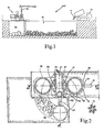
- Fig. 1 is a side, section view of an organic-waste collection centre provided with a dehumidification device according to the invention;
- Fig. 2 is a plan view of the dehumidification device according to the invention;
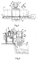
- Fig. 3 is a longitudinal section view, made along line III-III and to an enlarged scale, of the dehumidification device of Fig. 2;
- Fig. 4 is a transversal section view, made along line IV-IV and to an enlarged scale, of the dehumidification device of Fig. 2;
- Figs. 5-9 diagrammatically show five successive operative steps of the device according to the invention.
-
- With initial reference to Fig. 1, a
dehumidification device 10 according to the invention is installed beside apit 12 into which atruck 13 unloads material consisting of the organic fraction of urban solid waste which has been collected by the so-called differentiated collection. Abridge crane 14 overhangingpit 12 is operated by an onboard operator to pick up successive portions of the organic material from the pit and to transfer them to thedehumidification device 10. - The
dehumidification device 10, shown in more detail in Figs. 2, 3 and 4, comprises a horizontal, flat,elongated bedplate 15 resting on the bank ofpit 12 and threedrums lower ends 53 are shut by the surface of the bedplate, which acts as a shutting means, while theirupper openings 52 are open to the atmosphere. - Moreover, each
drum edge 40 extending along its upper lip. Shifting means 19, e.g. a hydraulic cylinder, are supported on a longitudinal end ofbedplate 15 and are provided with a pushingmember 20 adapted to engage an annularsalient portion 61 of the wall of the adjacent cylinder (cylinder 16 in the figure) in order to shift the latter and the adjacent drums alongbedplate 15. - A longitudinal middle portion of
bedplate 15 consists of a substantially plane, rigid section 55. Two parallel,vertical walls cross-piece 25 on their upper ends, rise from the opposite sides of section 55. Cross-piece 25 has avertical hole 26 in which is slidable apiston 27 of a squeezingcylinder 28. Asqueezing plate 29, whose diameter substantially matches the internal diameter of the drums, is fastened to the lower end ofpiston 27. - A horizontal
swivel arm 30 is hinged about avertical axis 32 and, to this purpose, is provided at one end 31 with a bush 39 which pivotally engages apivot 41 attached tocross-piece 25. Twolifting cylinders free end 59 and on a middle point P of the arm respectively. The rods oflifting cylinders respective hooks edge 40. Acrown gear 42 is coaxially keyed to bush 39, and is engaged by achain 43, whoseopposite ends linear actuators cross-piece 25. - The periphery of
bedplate 15 is surrounded withgutters 60 leading to a fluid-collection tank S (only diagrammed in Figs. 5-9). The gutters are covered by respective grids 58 adapted to screen any solid residuals. Grids 58 can be tipped towards adownload area 56 on one side ofbedplate 15. - The operation of the device, as diagrammed in Figs. 5-9, will be now described.
Organic material 111 picked bybridge crane 14 is downloaded into drum 160 (Fig. 5) supported on aloading area 48 of the bedplate; when filled,drum 160 is shifted by shiftingmeans 19 to asqueezing area 49 below cylinder 28 (Fig. 6). As shown in Fig. 6, during its translation,drum 160 pushes theadjacent drum 170, the latter being filled with organic material which has been already pressed as stated below with reference todrum 160, to arest area 50. Fig. 5 shows how the squeezing cylinder is operated to drivesqueezing plate 29 intodrum 160 throughupper opening 52. Accordingly, the organic material insidedrum 160 is pressed and, while the solid organic material is retained in the enclosed chamber delimited by the drum, the squeezing plate and the substantially plane, rigid section 55 of the bedplate, the excess fluid is drained through theholes 57 on the wall of the drum and flows intogutters 60. - In the meantime (Figs. 5-8),
horizontal arm 30 driven bylinear actuators drum 180 fromrest area 50 toloading area 48, while transiting abovedownload area 56 where the drum is emptied as stated below with reference todrum 170. Afterdrum 180 being placed inloading area 48,arm 30 is swivelled (Fig. 8) to carryhooks lifting cylinders 135, 136 underedge 140 ofdrum 170. By operatinglifting cylinders 135, 136,drum 170 is then picked up and carried byarm 30 abovedownload area 56 near bedplate 15 (Fig. 9), and pressedorganic material 211 is downloaded by gravity through lower end ofdrum 170. - In the meantime, the
empty drum 180 is loaded (Fig. 8) and then shifted to squeezingarea 49 by pushing member 20 (Fig. 9), so thatdrum 160, which contains pressed organic material, is displaced torest area 50. Accordingly,loading area 48 is free to receivedrum 170 fromarm 30, and so on. - In practice, three
drums - By the above described procedure, the organic material is effectively prepared for the subsequent oxygenation treatments. By adjusting the pressure exerted by squeezing
cylinder 28, the amount of fluid drained drum also be adjusted depending on the requirements. The dehumidified material is reduced in weight and volume, so that it will be easier and cheaper to be conveyed. The dehumidification device of the invention is also easy to integrate in traditionalwaste collection pits 12, such as that shown in Fig. 1, because of its small overall size. - A further advantage of this device is its sturdy structure, which allows the pressure exerted by squeezing
cylinder 28 upon the organic material in the drum to be reacted by a section of the bedplate which is suitably reinforced to be rigid and rugged. Moreover, the device according to the invention may be cheaply manufactured, by means of known processes and equipment commonly employed in this field. - The invention can be changed in different ways within the scope of its inventive concept, and all the details can be replaced with other technically equivalent elements. For example, the device can include a different number of cylindrical drums, in order to optimise its operation according to the requirements. The rotation of
horizontal arm 30 can be alternatively achieved by a motor driving a crown gear integral with bush 39 of the arm via gears, or by any other known device that will be obvious for the person skilled in the art.Arm 30 can be also substituted by other means adapted to allow the extraction of the squeezed material through the lower end of the drum, e.g. a sliding shutter on the bedplate. Moreover, although in the preferred embodiment the material is downloaded by gravity, downloading can be forced by inserting an extra ejection piston overhanging the download area, which is operated in case the weight of the material in the cylinder is not sufficient to cause the material to fall into the download area.
Claims (17)
- A device for dehumidifying organic waste, characterized in that it comprisesa bedplate (15),at least one drum (16, 17, 18) supportable on the bedplate (15), adapted to receive organic material and provided with an upper opening (52) and a open lower end (53),shutting means for said lower end,squeezing means (28) provided with a squeezing plate (29) whose diameter substantially matches the internal diameter of the drums and adapted to drop into the drum (16, 17, 18) through the upper opening (52), the lower end being shut, for pressing the organic material and causing its fluid fraction to be drained through holes (57) made on at least one of the walls of the enclosed chamber delimited by the drum, the squeezing plate (29) and the shutting means.
- The device of claim 1, characterized in that said shutting means consist of a the upper surface of the bedplate (15) below said squeezing plate (29).
- The device of claim 1 or 2, characterized in that it comprises transport means adapted to shift said drum (16, 17, 18) from a position in which its lower end (53) is shut to a position in which the lower end is open, above a download area (56) adapted to receive the dehumidified organic material in the drum falling by gravity.
- The device of claim 3, characterized in that said bedplate (15) is elongated and is provided with a loading area (48) for the organic material to be dehumidified, a squeezing area (49) for the organic material on the bedplate, and a rest area (50) for the drum to be emptied, which areas are contiguous along the longitudinal extension of the bedplate.
- The device of claim 4, characterized in that said transport means comprise shifting means (19) adapted to shift the drum (16, 17, 18) from the loading area (48) to the squeezing area (49) and from the squeezing area (49) to the rest area (50), and transfer means adapted to pick up the drum from the rest area (50), then to carry it to said position in which the lower end is open (51) for downloading the material, and finally to restore the drum on said loading area (48).
- The device of claim 5, characterized in that said shifting means (19) are provided with a pushing member (29) adapted to engage the side wall of the drum (16, 17, 18) for shifting it along the bedplate (15).
- The device of claim 3, characterized in that said download area (56) is arranged on one side of said bedplate (15).
- The device of claims 4 or 7, characterized in that said transfer means are a substantially horizontal swivel arm (30) hinged about a vertical axis (32) between said loading area (48) and said rest area (50), and provided with clasping means for clasping the drum (16, 17, 18).
- The device of claim 8, characterized in that said swivel arm (30) is provided with a crown gear (42) that is coaxial with said vertical axis (32) and is engaged by a chain (43) whose opposite ends (44, 45) are fastened to the rods of respective linear actuators (46, 47) connected to the bedplate (15) and adapted to swivel the swivel arm (30).
- The device of claim 9, characterized in that said drum (16, 17, 18) is externally provided with an edge (40) extending along its upper lip, and in that said clasping means comprise two lifting cylinders (35, 36), which hang at right angles on the free end (59) and on a middle point (P) of the arm and are provided with rods supporting respective hooks (33, 34) adapted to engage the edge (40).
- The device of claim 1, characterized in that said holes (57) are made on the side wall of the container (16, 17, 18).
- The device of anyone of the above claims, characterized in that it comprises three of said substantially cylindrical containers (16, 17, 18) adapted to cyclically follow one another to engage eachone of said loading area (48), squeezing area (49), picking area (50) and to transit above said download area (56).
- The device of anyone of the above claims, characterized in that it comprises gutters 60 surrounding periphery of bedplate (15) and leading to a fluid-collection tank.
- The device of claim 13, characterized in that said gutters (60) are covered by grids (58) for screening any solid residuals.
- The device of claim 14, characterized in that said grids (58) are overturnable towards download area (56).
- The device of claim 1, characterized in that said squeezing means are a squeezing cylinder (28) provided with a piston (27) to which is coaxially connected to said squeezing plate (29).
- The device of claim 16, characterized in that it comprises two vertical walls (23, 24) rising from the opposite sides of said substantially plane, rigid section (55) and supporting a cross-piece (25) on their upper ends, cross-piece (25) having a vertical hole (26) in which is slidable the piston (27) of said squeezing cylinder (28).
Applications Claiming Priority (2)
| Application Number | Priority Date | Filing Date | Title |
|---|---|---|---|
| ITTO20020388 | 2002-05-10 | ||
| IT2002TO000388A ITTO20020388A1 (en) | 2002-05-10 | 2002-05-10 | DEVICE FOR THE DEHUMIDIFICATION OF ORGANIC WASTE. |
Publications (2)
| Publication Number | Publication Date |
|---|---|
| EP1361043A2 true EP1361043A2 (en) | 2003-11-12 |
| EP1361043A3 EP1361043A3 (en) | 2005-07-20 |
Family
ID=27639059
Family Applications (1)
| Application Number | Title | Priority Date | Filing Date |
|---|---|---|---|
| EP03009498A Withdrawn EP1361043A3 (en) | 2002-05-10 | 2003-04-28 | Device for dehumidifying organic waste |
Country Status (2)
| Country | Link |
|---|---|
| EP (1) | EP1361043A3 (en) |
| IT (1) | ITTO20020388A1 (en) |
Cited By (2)
| Publication number | Priority date | Publication date | Assignee | Title |
|---|---|---|---|---|
| ITPD20110337A1 (en) * | 2011-10-24 | 2013-04-25 | Davide Masiero | VERTICAL PRESS WITH FACILITATED EXHAUST OF THE RESIDUE |
| FR3032907A1 (en) * | 2015-02-19 | 2016-08-26 | Environnemental Sediments Treat | PRESS FOR TREATING SEDIMENTS FROM A BOTTOM OF AN AQUEOUS ENVIRONMENT |
Citations (7)
| Publication number | Priority date | Publication date | Assignee | Title |
|---|---|---|---|---|
| BE353342A (en) * | ||||
| DE686370C (en) * | 1937-04-10 | 1940-01-08 | Bucher Guyer Maschf | Hydraulic vacuum basket press |
| FR974333A (en) * | 1948-08-13 | 1951-02-21 | Fruit and grape press | |
| US3992905A (en) * | 1975-06-30 | 1976-11-23 | Mcgraw-Edison Company | Compression extractor device for laundry goods |
| US4397231A (en) * | 1980-03-31 | 1983-08-09 | Burgin Kermit H | Apparatus for producing and collecting a liquid extract and a dry by-product from a mash |
| JPS61189900A (en) * | 1985-02-15 | 1986-08-23 | Kubota Ltd | Scum dehydrator |
| JP2002045996A (en) * | 2000-08-07 | 2002-02-12 | Nachi Fujikoshi Corp | Press |
-
2002
- 2002-05-10 IT IT2002TO000388A patent/ITTO20020388A1/en unknown
-
2003
- 2003-04-28 EP EP03009498A patent/EP1361043A3/en not_active Withdrawn
Patent Citations (7)
| Publication number | Priority date | Publication date | Assignee | Title |
|---|---|---|---|---|
| BE353342A (en) * | ||||
| DE686370C (en) * | 1937-04-10 | 1940-01-08 | Bucher Guyer Maschf | Hydraulic vacuum basket press |
| FR974333A (en) * | 1948-08-13 | 1951-02-21 | Fruit and grape press | |
| US3992905A (en) * | 1975-06-30 | 1976-11-23 | Mcgraw-Edison Company | Compression extractor device for laundry goods |
| US4397231A (en) * | 1980-03-31 | 1983-08-09 | Burgin Kermit H | Apparatus for producing and collecting a liquid extract and a dry by-product from a mash |
| JPS61189900A (en) * | 1985-02-15 | 1986-08-23 | Kubota Ltd | Scum dehydrator |
| JP2002045996A (en) * | 2000-08-07 | 2002-02-12 | Nachi Fujikoshi Corp | Press |
Non-Patent Citations (2)
| Title |
|---|
| PATENT ABSTRACTS OF JAPAN vol. 011, no. 014 (M-553), 14 January 1987 (1987-01-14) & JP 61 189900 A (KUBOTA LTD), 23 August 1986 (1986-08-23) * |
| PATENT ABSTRACTS OF JAPAN vol. 2002, no. 06, 4 June 2002 (2002-06-04) & JP 2002 045996 A (NACHI FUJIKOSHI CORP), 12 February 2002 (2002-02-12) * |
Cited By (2)
| Publication number | Priority date | Publication date | Assignee | Title |
|---|---|---|---|---|
| ITPD20110337A1 (en) * | 2011-10-24 | 2013-04-25 | Davide Masiero | VERTICAL PRESS WITH FACILITATED EXHAUST OF THE RESIDUE |
| FR3032907A1 (en) * | 2015-02-19 | 2016-08-26 | Environnemental Sediments Treat | PRESS FOR TREATING SEDIMENTS FROM A BOTTOM OF AN AQUEOUS ENVIRONMENT |
Also Published As
| Publication number | Publication date |
|---|---|
| ITTO20020388A1 (en) | 2003-11-10 |
| ITTO20020388A0 (en) | 2002-05-10 |
| EP1361043A3 (en) | 2005-07-20 |
Similar Documents
| Publication | Publication Date | Title |
|---|---|---|
| US4520718A (en) | Equipment for massaging of meat | |
| CN214234792U (en) | Coating and spin-drying production line | |
| HUE025153T2 (en) | Apparatus for automatically emptying bags | |
| KR101981268B1 (en) | Food waste collecting vehicle | |
| EP1361043A2 (en) | Device for dehumidifying organic waste | |
| CA1191810A (en) | Grain handling system | |
| EP1048592A1 (en) | Waste collection device | |
| GB1601099A (en) | Mixing apparatus for concrete or other bulk material | |
| EP2712828B1 (en) | Apparatus for loading and evenly distributing material into a container | |
| US3861086A (en) | Drum tumbling apparatus | |
| US6929202B2 (en) | Method and arrangement for feeding wood batches into a pressure grinder | |
| CN214234742U (en) | Full-automatic coating machine | |
| GB2043012A (en) | Conveying articles between liquidtreatment stations | |
| GB2223733A (en) | Device for tipping containers | |
| AU774630B2 (en) | Apparatus for emptying receptacle | |
| EP3476771B1 (en) | Loading system for lifting and emptying a container into a collector, refuse truck provided with such a loading system and method therefor | |
| CN111252520A (en) | Automatic change beet stacker | |
| CN110615215A (en) | Buried garbage compression equipment and garbage compression method | |
| CN220398987U (en) | Sampling and bag breaking integrated machine | |
| CN215513762U (en) | Remove convenient conveyer for waterproof material production | |
| CN218841578U (en) | Auxiliary maintenance equipment for heating boiler | |
| CN211196541U (en) | Water conservancy float-garbage ship | |
| RU63255U1 (en) | RELOADING AND SORTING INSTALLATION | |
| JPS5817424Y2 (en) | Automatic cleaning and alignment device for seafood | |
| JP4174594B2 (en) | Drum can contents input device |
Legal Events
| Date | Code | Title | Description |
|---|---|---|---|
| PUAI | Public reference made under article 153(3) epc to a published international application that has entered the european phase |
Free format text: ORIGINAL CODE: 0009012 |
|
| AK | Designated contracting states |
Kind code of ref document: A2 Designated state(s): AT BE BG CH CY CZ DE DK EE ES FI FR GB GR HU IE IT LI LU MC NL PT RO SE SI SK TR |
|
| AX | Request for extension of the european patent |
Extension state: AL LT LV MK |
|
| PUAL | Search report despatched |
Free format text: ORIGINAL CODE: 0009013 |
|
| AK | Designated contracting states |
Kind code of ref document: A3 Designated state(s): AT BE BG CH CY CZ DE DK EE ES FI FR GB GR HU IE IT LI LU MC NL PT RO SE SI SK TR |
|
| AX | Request for extension of the european patent |
Extension state: AL LT LV MK |
|
| RIC1 | Information provided on ipc code assigned before grant |
Ipc: 7B 30B 9/30 B Ipc: 7B 30B 9/04 A |
|
| AKX | Designation fees paid | ||
| REG | Reference to a national code |
Ref country code: DE Ref legal event code: 8566 |
|
| STAA | Information on the status of an ep patent application or granted ep patent |
Free format text: STATUS: THE APPLICATION IS DEEMED TO BE WITHDRAWN |
|
| 18D | Application deemed to be withdrawn |
Effective date: 20060421 |