EP1360899B1 - Rotation support structure for dual-bearing reel - Google Patents
Rotation support structure for dual-bearing reel Download PDFInfo
- Publication number
- EP1360899B1 EP1360899B1 EP03009623A EP03009623A EP1360899B1 EP 1360899 B1 EP1360899 B1 EP 1360899B1 EP 03009623 A EP03009623 A EP 03009623A EP 03009623 A EP03009623 A EP 03009623A EP 1360899 B1 EP1360899 B1 EP 1360899B1
- Authority
- EP
- European Patent Office
- Prior art keywords
- bearing
- component
- dual
- spool
- fluid
- Prior art date
- Legal status (The legal status is an assumption and is not a legal conclusion. Google has not performed a legal analysis and makes no representation as to the accuracy of the status listed.)
- Expired - Lifetime
Links
- 230000009977 dual effect Effects 0.000 title claims abstract description 36
- 239000012530 fluid Substances 0.000 claims abstract description 66
- 239000000314 lubricant Substances 0.000 claims abstract description 10
- 230000005291 magnetic effect Effects 0.000 claims description 29
- 239000005871 repellent Substances 0.000 claims description 13
- 238000005096 rolling process Methods 0.000 claims description 13
- 239000011553 magnetic fluid Substances 0.000 claims description 11
- 238000004804 winding Methods 0.000 claims description 7
- 230000004044 response Effects 0.000 claims description 3
- 230000009467 reduction Effects 0.000 abstract description 14
- 230000007246 mechanism Effects 0.000 description 33
- 238000005266 casting Methods 0.000 description 17
- 239000010408 film Substances 0.000 description 11
- 238000010168 coupling process Methods 0.000 description 5
- 238000003754 machining Methods 0.000 description 5
- 230000002829 reductive effect Effects 0.000 description 5
- 238000005859 coupling reaction Methods 0.000 description 4
- 238000000034 method Methods 0.000 description 4
- 238000007789 sealing Methods 0.000 description 4
- 239000007787 solid Substances 0.000 description 4
- 210000003813 thumb Anatomy 0.000 description 4
- 230000008878 coupling Effects 0.000 description 3
- 239000003921 oil Substances 0.000 description 3
- 230000036961 partial effect Effects 0.000 description 3
- YCKRFDGAMUMZLT-UHFFFAOYSA-N Fluorine atom Chemical compound [F] YCKRFDGAMUMZLT-UHFFFAOYSA-N 0.000 description 2
- 230000015572 biosynthetic process Effects 0.000 description 2
- 230000003247 decreasing effect Effects 0.000 description 2
- 229910052731 fluorine Inorganic materials 0.000 description 2
- 239000011737 fluorine Substances 0.000 description 2
- 230000000670 limiting effect Effects 0.000 description 2
- 239000000463 material Substances 0.000 description 2
- 239000002184 metal Substances 0.000 description 2
- 238000005240 physical vapour deposition Methods 0.000 description 2
- 230000002265 prevention Effects 0.000 description 2
- 229920005989 resin Polymers 0.000 description 2
- 239000011347 resin Substances 0.000 description 2
- 230000003068 static effect Effects 0.000 description 2
- 239000010409 thin film Substances 0.000 description 2
- XLYOFNOQVPJJNP-UHFFFAOYSA-N water Substances O XLYOFNOQVPJJNP-UHFFFAOYSA-N 0.000 description 2
- 241000251468 Actinopterygii Species 0.000 description 1
- 239000004215 Carbon black (E152) Substances 0.000 description 1
- XUIMIQQOPSSXEZ-UHFFFAOYSA-N Silicon Chemical compound [Si] XUIMIQQOPSSXEZ-UHFFFAOYSA-N 0.000 description 1
- 230000004308 accommodation Effects 0.000 description 1
- 230000005540 biological transmission Effects 0.000 description 1
- 238000005260 corrosion Methods 0.000 description 1
- 230000007797 corrosion Effects 0.000 description 1
- 239000000428 dust Substances 0.000 description 1
- 230000000694 effects Effects 0.000 description 1
- 230000005294 ferromagnetic effect Effects 0.000 description 1
- 239000013505 freshwater Substances 0.000 description 1
- 229930195733 hydrocarbon Natural products 0.000 description 1
- 150000002430 hydrocarbons Chemical class 0.000 description 1
- 230000001939 inductive effect Effects 0.000 description 1
- 238000010147 laser engraving Methods 0.000 description 1
- 239000007788 liquid Substances 0.000 description 1
- 230000004048 modification Effects 0.000 description 1
- 238000012986 modification Methods 0.000 description 1
- 239000002245 particle Substances 0.000 description 1
- 230000000149 penetrating effect Effects 0.000 description 1
- 230000002093 peripheral effect Effects 0.000 description 1
- 238000003825 pressing Methods 0.000 description 1
- 230000008569 process Effects 0.000 description 1
- 230000002940 repellent Effects 0.000 description 1
- 230000000284 resting effect Effects 0.000 description 1
- 229910052710 silicon Inorganic materials 0.000 description 1
- 239000010703 silicon Substances 0.000 description 1
- 239000002904 solvent Substances 0.000 description 1
- 239000004094 surface-active agent Substances 0.000 description 1
- 229920003002 synthetic resin Polymers 0.000 description 1
- 239000000057 synthetic resin Substances 0.000 description 1
Images
Classifications
-
- A—HUMAN NECESSITIES
- A01—AGRICULTURE; FORESTRY; ANIMAL HUSBANDRY; HUNTING; TRAPPING; FISHING
- A01K—ANIMAL HUSBANDRY; CARE OF BIRDS, FISHES, INSECTS; FISHING; REARING OR BREEDING ANIMALS, NOT OTHERWISE PROVIDED FOR; NEW BREEDS OF ANIMALS
- A01K89/00—Reels
- A01K89/015—Reels with a rotary drum, i.e. with a rotating spool
-
- A—HUMAN NECESSITIES
- A01—AGRICULTURE; FORESTRY; ANIMAL HUSBANDRY; HUNTING; TRAPPING; FISHING
- A01K—ANIMAL HUSBANDRY; CARE OF BIRDS, FISHES, INSECTS; FISHING; REARING OR BREEDING ANIMALS, NOT OTHERWISE PROVIDED FOR; NEW BREEDS OF ANIMALS
- A01K89/00—Reels
-
- A—HUMAN NECESSITIES
- A01—AGRICULTURE; FORESTRY; ANIMAL HUSBANDRY; HUNTING; TRAPPING; FISHING
- A01K—ANIMAL HUSBANDRY; CARE OF BIRDS, FISHES, INSECTS; FISHING; REARING OR BREEDING ANIMALS, NOT OTHERWISE PROVIDED FOR; NEW BREEDS OF ANIMALS
- A01K89/00—Reels
- A01K89/015—Reels with a rotary drum, i.e. with a rotating spool
- A01K89/0192—Frame details
- A01K89/0193—Frame details with bearing features
-
- F—MECHANICAL ENGINEERING; LIGHTING; HEATING; WEAPONS; BLASTING
- F16—ENGINEERING ELEMENTS AND UNITS; GENERAL MEASURES FOR PRODUCING AND MAINTAINING EFFECTIVE FUNCTIONING OF MACHINES OR INSTALLATIONS; THERMAL INSULATION IN GENERAL
- F16C—SHAFTS; FLEXIBLE SHAFTS; ELEMENTS OR CRANKSHAFT MECHANISMS; ROTARY BODIES OTHER THAN GEARING ELEMENTS; BEARINGS
- F16C21/00—Combinations of sliding-contact bearings with ball or roller bearings, for exclusively rotary movement
Landscapes
- Life Sciences & Earth Sciences (AREA)
- Environmental Sciences (AREA)
- Animal Husbandry (AREA)
- Biodiversity & Conservation Biology (AREA)
- Engineering & Computer Science (AREA)
- General Engineering & Computer Science (AREA)
- Mechanical Engineering (AREA)
- Sliding-Contact Bearings (AREA)
- Storage Of Web-Like Or Filamentary Materials (AREA)
- Rolls And Other Rotary Bodies (AREA)
Abstract
Description
- This invention generally relates to rotation support structures. More specifically, the present invention relates to rotation support structures for high-speed rotating components of dual-bearing reels.
- Dual-bearing reels, and in particular bait casting reels and electrically-driven reels, are equipped with components that rotate at high speeds. In the case of bait casting reels, the spool rotates at high speeds of about 20,000 rpm when casting. To support the components rotating at these high speeds, ball bearings, which are rolling bearings, are conventionally used.
- When using ball bearings as a support structure for rotating components, the rotation performance may decrease, since ball bearings have a tiny rotation resistance. For example, if a spool of a bait casting reel is supported by a ball bearing, then the flying distance may decrease due to the rotation resistance during casting. Conventionally, to address this problem, a contact portion that contacts the inner race of the ball bearing with a small gap therebetween, is formed on the spool shaft. The contact portion is formed with a width that is smaller than the width of the inner race. During high-speed rotation of the spool, the inner race and the contact portion are caused to slide, and during low-speed of the spool, the spool is supported by the ball bearing at the contact portion.
- With the conventional rotation support structure using a ball bearing, the inner race and the contact portion slide during high-speed rotation, so that the rotation resistance between the inner race and the ball bearing can be ignored, and a reduction of the rotation performance can be better suppressed than when there is no sliding. However, since sliding occurs between the inner race and the contact portion during high-speed rotation, friction is generated at this portion. For this reason, some reduction in the rotation performance due to friction losses occurs after all.
- For example US-A-5,402,953 discloses a conventional shaft supporting structure for a fishing reel and US-A-5,129,739 discloses a bearing with dynamic pressure grooves.
- In view of the above, there exists a need for rotation support structure for a dual-bearing reel which overcomes the above mentioned problems in the prior art. This invention addresses this need in the prior art as well as other needs, which will become apparent to those skilled in the art from this disclosure.
- It is thus a purpose of the present invention to provide a support structure for a high-speed rotation portion of a dual-bearing reel, with which a reduction of the rotation performance during high-speed rotation can be successfully suppressed.
- In a rotation support structure for a dual-bearing reel according to the first aspect of the invention, a support structure for a high-speed rotation portion of a dual-bearing reel includes a first component, a second component, and a fluid bearing. The second component is disposed on an inner circumferential side of the first component and can rotate relative to the first component. The fluid bearing is disposed between the first and second components for forming a fluid lubricant film between the two components.
- With this rotation support structure, a fluid bearing is provided that contactlessly supports the two components by forming a fluid lubricant film between the first component and the second component. Here, the first component and the second component are linked by the fluid bearing. Therefore, the rotation resistance becomes smaller than for a support structure with a ball bearing. Also, no friction occurs between solid bodies, so that also the friction resistance is reduced. Therefore, a reduction of the rotation performance can be successfully averted. Furthermore, it is possible to form the fluid bearing as a one-piece, unitary member with the components. Therefore, there is no need for a special accommodation space. Accordingly, it is possible to prevent the dual-bearing reel from becoming large.
- Moreover, one of a rolling bearing and a sliding bearing arranged between the first component and the second component. The fluid bearing is disposed between an outer circumferential surface of the second component and an inner circumferential surface of the one of the rolling bearing and sliding bearing. With this configuration, even when the second component is rotated with respect to the rolling bearing or sliding bearing, the second component is supported by the one of the rolling bearing and the sliding bearing during low-speed rotation, and by the fluid bearing during high-speed rotation. Accordingly, a reduction of the rotation performance can be averted in all rotation regions, including low-speed rotation such as when winding up line and high-speed rotation such as when casting.
- According to the rotation support structure for a dual-bearing reel of the second aspect of the present invention, in the structure according to the first aspect, the fluid lubricant film formation means has a plurality of groove portions formed in an outer circumferential surface of the second component, which rotates with respect to the first component. With this configuration, the rotation stability can be improved and a high rotation precision can be maintained by forming grooves in the outer circumferential surface of the second component, which rotates with respect to the first component.
- According to the rotation support structure for a dual-bearing reel of third aspect of the present invention, in the structure according to the first or the second aspect, the first component is a reel unit of the dual-bearing reel, the second component is a spool shaft rotatively supported by the reel unit, and the fluid bearing is disposed on at least one end of the spool shaft. With this configuration, a reduction of the rotation performance of the spool rotating together with the spool shaft with respect to the reel unit can be successfully averted, and the reel can be made more compact.
- According to the rotation support structure for a dual-bearing reel of the fourth aspect of the present invention, the structure according to the first aspect further includes a rolling bearing or a sliding bearing arranged between the first component and the second component, and the fluid bearing is disposed between an inner circumferential surface of the first component and an outer circumferential surface of the one of the rolling bearing and sliding bearing. With this configuration, even when the first component is rotated with respect to the one of the rolling bearing and the sliding bearing, the first component is supported by the rolling bearing or sliding bearing during low-speed rotation and by the fluid bearing during high-speed rotation. Accordingly, a reduction of the rotation performance can be averted in all rotation regions, including low-speed rotation such as when winding up line and high-speed rotation such as when casting.
- According to the rotation support structure for a dual-bearing reel of the fifth aspect of the present invention, in the structure according to the first through fifth aspects, the fluid bearing has a plurality of groove portions formed in an inner circumferential surface of the first component, which rotates with respect to the second component. With this configuration, the rotation stability can be improved and a high rotation precision can be maintained by forming grooves in the outer circumferential surface of the first component, which rotates with respect to the second component.
- According to the rotation support structure for a dual-bearing reel of the sixth aspect of the present invention, in the structure according to the fourth or fifth aspect, the first component is a spool rotating with respect to a reel unit of the dual-bearing reel, while the second component is a spool shaft mounted non-rotatively to the reel unit and piercing the center of the spool. The fluid bearing is disposed on at least one end of the spool. With this configuration, a reduction of the rotation performance of the spool rotating together with the spool shaft can be successfully averted, and the spool and the reel can be made more compact.
- According to the rotation support structure for a dual-bearing reel of the seventh aspect of the present invention, the structure according to any of the first through sixth aspects further includes a seal member that seals a gap between the first component and the second component on at least one side of the fluid bearing. With this configuration, the inside of the fluid bearing is sealed by a seal member, so that fluctuations in the dynamic pressure or the static pressure due to the intrusion of foreign matter can be averted, and problems due to the intrusion of foreign matter can be prevented.
- According to the rotation support structure for a dual-bearing reel of the eighth aspect of the present invention, in the structure according to the seventh aspect, the seal member is a low-friction seal. With this configuration, a low-friction seal with little rotation loss is used for the seal member, so that reductions of the rotation performance due to the seal member can be averted.
- According to the rotation support structure for a dual-bearing reel of the ninth aspect of the present invention, in the structure according to the eighth aspect, the low-friction seal is a magnetic seal having a magnetic fluid that is held by either of the two components. With this configuration, the intrusion of foreign matter can be efficiently prevented with the magnetic seal using a magnetic fluid, and in case of a fluid bearing using a fluid different from air, can also function to hold the fluid in addition to sealing.
- According to the rotation support structure for a dual-bearing reel of the tenth aspect of the present invention, in the structure according to the eihth aspect, the low-friction seal is a water-repellent seal having a water-repellent film layer that is arranged on a portion facing away from at least one of the two components. With this configuration, the seal member is made of a water-repellent film layer, so that, in particular, the intrusion of liquids such as freshwater and saltwater can be prevented effectively, and the corrosion resistance of the components can be maintained easily.
- These and other objects, features, aspects and advantages of the present invention will become apparent to those skilled in the art from the following detailed description, which, taken in conjunction with the annexed drawings, discloses a preferred embodiment of the present invention.
- Referring now to the attached drawings which form a part of this original disclosure:
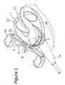
- Figure 1 is a perspective view of a dual-bearing reel according to one embodiment of the present invention;
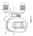
- Figure 2 is a plan view of the dual-bearing reel according to the embodiment of the present invention;
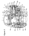
- Figure 3 is a plan cross-sectional view of the dual-bearing reel according to the embodiment of the present invention;
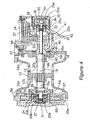
- Figure 4 is a magnified cross-sectional view of the spool support portion according to the embodiment of the present invention;
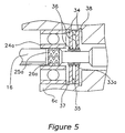
- Figure 5 is a partial cross-sectional view of a fluid bearing support portion according to the embodiment of the present invention;
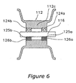
- Figure 6 is a partial cross-sectional view of a rotation support portion according to another embodiment of the present invention; and
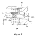
- Figure 7 is a partial cross-sectional view of a rotation support portion according to still another embodiment.
- Selected embodiments of the present invention will now be explained with reference to the drawings. It will be apparent to those skilled in the art from this disclosure that the following description of the embodiments of the present invention is provided for illustration only, and not for the purpose of limiting the invention as defined by the appended claims and their equivalents.
- As shown in Figures 1 and 2, a dual-bearing reel employing a seal mechanism in accordance with an embodiment of the present invention is a low-profile type reel for bait casting. This reel includes a reel unit 1, a spool rotation handle 2 that is mounted to one side of the reel unit 1 and a
spool 12 for winding fishing line in response to rotation of thehandle 2, which is mounted rotatively and detachably to the inside of the reel unit 1. Astar drag 3 for adjusting drag is disposed on the same side of the reel unit 1 as thehandle 2. - The
handle 2 is of the double-handle type and has a plate-shapedhandle arm 2a and grips 2b that are attached rotatively to both ends ofhandle arm 2a. As shown in Figure 3, thehandle arm 2a is fastened with twoscrews 2e to abase plate 2c that is fastened non-rotatively to the near end of ahandle shaft 30 with anut 2d. Thisnut 2d is accommodated inside thehandle arm 2a, so as not to rotate. In this manner, the outer lateral surface of thehandle arm 2a can be configured as a seamless smooth surface, achieving a structure in which fishing line does not easily get caught up. - As shown in Figure 3, the reel main unit 1 has a
frame 5, and afirst side cover 6a and asecond side cover 6b that are mounted to both sides of theframe 5. Furthermore, as shown in Figure I and Figure 2, the reel unit 1 also has a front cover 7 covering the front and athumb rest 8 covering the top portion. Theframe 5 includes a pair ofside plates portions 5c connecting theside plates portions 5c on the lower side. - The
first side cover 6a can be opened or closed with respect to theframe 5, and is mounted pivotally to theframe 5 to make it possible to attach and detach thespool 12. Thesecond side cover 6b is screwed to theframe 5. The front cover 7 is mounted between theside plates - As shown in Figure 3, the
spool 12, alevel wind mechanism 15 and aclutch lever 17 are disposed inside theframe 5. Thespool 12 is arranged perpendicularly to the fishing rod R. Thelevel wind mechanism 15 is for uniformly winding fishing line around thespool 12. Theclutch lever 17 is where the thumb is placed during pitching. Agear mechanism 18, aclutch mechanism 13, a clutch engage/disengage mechanism 19, an engage/disengage control mechanism 20, adrag mechanism 21, and acasting control mechanism 22 are disposed in the space between theframe 5 and thesecond side cover 6b. Thegear mechanism 18 transmits rotational force from thehandle 2 to thespool 12 and thelevel wind mechanism 15. The clutch engage/disengage mechanism 19 engages and disengages theclutch mechanism 13. The engage/disengage control mechanism 20 controls the engaging and disengaging of theclutch mechanism 13 in response to the operation of theclutch lever 17. Thecasting control mechanism 22 adjusts the resistance that develops when thespool 12 rotates. Also, acentrifugal braking mechanism 23 for preventing backlash when casting is disposed between theframe 5 and thefirst side cover 6a. - As shown in Figure 4, the
spool 12 has saucer-shapedflange portions 12a on both ends and acylindrical bobbin portion 12b between the twoflange portions 12a. Thespool 12 also has acylindrical boss 12c. Thecylindrical boss 12c is formed on the inner side of thebobbin portion 12b at substantially the center with respect to the axial direction as a one-piece unitary member with thebobbin portion 12b. Thespool 12 is fixed non-rotatively, for example by serration coupling, to aspool shaft 16 penetrating theboss 12c. The fixation is not limited to serration coupling, and other coupling methods such as key coupling or spline-coupling can be employed as well. - The
spool shaft 16 penetrates theside plate 5b and extends outward beyond thesecond side cover 6b. This end of thespool shaft 16 is supported rotatively with aball bearing 24a and afluid bearing 25a at aboss 6c, which is provided at thesecond side cover 6b. The other end of thespool shaft 16 is supported rotatively with aball bearing 24b and afluid bearing 25b at a brake case 65 (explained below) inside thecentrifugal braking mechanism 23. Here, a small gap is formed between the outer circumferential surface of thespool shaft 16 and the inner races of theball bearings fluid bearings fluid bearings spool 12. Moreover, during relatively slow rotation, for example when winding up fishing line, theball bearings spool shaft 16, whereas thefluid bearings spool shaft 16 during relatively fast rotation, for example when casting. As shown in Figure 4,magnetic seals ball bearing 24a and to the inner axial side of theball bearing 24b. - As shown in Figure 5, the
fluid bearings pressure generation grooves 26a in which a lubricant film of air serving as a fluid is formed between the inner circumferential surface of theball bearings spool shaft 16. The lubricant film of air is formed at the outer circumferential surface of the portion of thespool shaft 16 where the bearings are mounted to generate dynamic pressure in the radial direction. The dynamicpressure generation grooves 26a, which generate dynamic pressure in the radial direction, have for example a triangular zig-zag pattern and are provided with a shape that generates dynamic pressure when thespool 12 is rotated fast in the direction letting off fishing line. The dynamicpressure generation grooves 26a rotatively support thespool shaft 16 while leaving a gap to the inner race of theball bearings pressure generation grooves 26a are formed by any of the machining methods known in the art, such as mechanical machining including laser engraving, by electrolytic machining using an electrode, or by a thin film formation process such as PVD (physical vapor deposition). Since these methods of forming grooves are well known in the art, detailed explanations of these methods are omitted herein. A stable rotation performance can be attained by keeping the machining precision of thefluid bearings ball bearings spool shaft 16 where the bearings are mounted, to not more than 5 µm, preferably not more than 2 µm, and even more preferably not more than 1 µm. - Thus, since the
fluid bearings spool shaft 16 rotatively but without contact, are provided between the inner race of theball bearing spool shaft 16, it is possible to suppress reductions of the rotation performance during high-speed rotation, and to prevent a reduction of the flying distance during casting. - The
magnetic seal 33a includes a pair of magnetic holding rings 34, aring magnet 35, and amagnetic fluid 36. The pair of magnetic holding rings 34 is fastened to theboss 6c at a certain spacing in the axial direction on the outer side of theball bearing 24a. Thering magnet 35 is sandwiched by the two magnetic holding rings 34. Themagnetic fluid 36 is disposed between the magnetic holding rings 34 and thespool shaft 16. Themagnetic seal 33a seals the gap between thespool shaft 16 and theboss 6c by holding themagnetic fluid 36 in a magnetic circuit constituted by thering magnet 35, the magnetic holding rings 34 and thespool shaft 16. - A locking
ring 37 for positioning the outer race of theball bearing 24a is fitted between the inner (left hand side in Figure 4)magnetic holding ring 34 and theball bearing 24a. In outward axial direction from the outermagnetic holding ring 34, an O-ring 38 is disposed between themagnetic holding ring 34 and theboss 6c. Themagnetic fluid 36 has ferromagnetic particles of several nm to several dozen nm dispersed stably, by using a surface active agent, in a solvent of hydrocarbon oil or fluorine oil. Thismagnetic seal 33a surrounds thespool shaft 16 with a fluid, so that themagnetic seal 33a can hermetically. Furthermore, since there is no solid contact at the sealing portions, no dust is generated. Moreover, since there is no solid sliding at the sealing portions, the loss-inducing torque is small and there is hardly any reduction in rotation performance. - The
magnetic seal 33b has a similar configuration as themagnetic seal 33a, and also includes a pair of magnetic holding rings 34, aring magnet 35, and amagnetic fluid 36. Thering magnet 35 is sandwiched by the two magnetic holding rings 34. Themagnetic fluid 36 is disposed between the magnetic holding rings 34 and thespool shaft 16. A lockingring 37 for positioning the outer race of theball bearing 24b is disposed between the outer (left hand side in Figure 4)magnetic holding ring 34 and theball bearing 24b. Inward from the innermagnetic holding ring 34, an O-ring 38 is fitted between themagnetic holding ring 34 and thebrake case 65. - The right end of a
large diameter portion 16a of thespool shaft 16 is disposed at a portion where theside plate 5b is pierced. Anengaging pin 16b, which is part of theclutch mechanism 13, is fixed in thespool shaft 16 at this place. The engagingpin 16b pierces thelarge diameter portion 16a through its diameter and protrudes radially from both sides. - Referring to Figure 3, the
gear mechanism 18 includes thehandle shaft 30, amain gear 31 fixed to thehandle shaft 30, acylindrical pinion gear 32 meshing with themain gear 31, agear 28a linked to the level wind mechanism, and a gear 28b that is fixed non-rotatively to thehandle shaft 30 and meshes with thegear 28a. The vertical position of thehandle shaft 30 of thisgear mechanism 18 is lower than the conventional position, in order to lower the height of thethumb rest 8. Thus, the lower portions of theside plate 5b and thesecond cover 6b, which house thegear mechanism 18, are positioned below the lower portions of theside plate 5a and thefirst side cover 6a. The front end of thehandle shaft 30 has a reduced diameter. A parallelbeveled portion 30a and an externally threadedportion 30b are formed on a large diameter portion and a small diameter portion of the front end. - The base end (left end in Figure 4) of the
handle shaft 30 is supported by theside plate 5b with abearing 57. An elastic rippedseal member 58 is fitted to the inner side of the base end of thehandle shaft 30. - The
pinion gear 32 has a teethedportion 32a, a meshingportion 32b and aconstricted portion 32c. The teethedportion 32a is formed on the outer circumferential portion on the right end in Figure 3 and meshes with themain gear 31. The meshingportion 32b is formed at the end on the other side. Theconstricted portion 32c is formed between the teethedportion 32a and the meshingportion 32b. The meshingportion 32b is made of a depression groove that is formed in the end surface of thepinion ear 32 along its diameter, and this is where theengagement pin 16b is passed through thespool shaft 16 and fastened. Thepinion gear 32 is supported by theside plate 5b with abearing 43. An elastic rippedseal member 59 is fitted to the inner side of thebearing 43. - Here, when the
pinion gear 32 is moved outward, and the meshingportion 32b and theengagement pin 16b in thespool shaft 16 are uncoupled, the rotational force from thehandle shaft 30 is not transmitted to thespool 12. The meshingportion 32b and theengagement pin 16b constitute theclutch mechanism 13. When theengagement pin 16b and the meshingportion 32b are engaged, then torque is transmitted directly from the large-diameter pinion gear 32, whose diameter is larger than that of thespool shaft 16, to thespool shaft 16, so that twisting deformations are reduced and the torque transmission efficiency is improved. - As shown in Figure 2, the
clutch lever 17 is disposed at the rear end of the pair ofside plates spool 12. A long hole (not shown in the drawings) is formed in theside plates frame 5, and arotation shaft 17a of theclutch lever 17 is supported rotatively by this long hole. Thus, theclutch lever 17 can slide vertically along the long hole. - As shown in Figure 3, the clutch engage/
disengage mechanism 19 includes aclutch yoke 40. Theclutch yoke 40 is disposed on the outer circumferential side of thespool shaft 16, and is supported by two pins 41 (only one of which is shown in the figure), such that theclutch yoke 40 can be shifted parallel to the axis of thespool shaft 16. It should be noted that thespool shaft 16 can rotate relatively to theclutch yoke 40. That is to say, even when thespool shaft 16 rotates, theclutch yoke 40 does not rotate. Furthermore, theclutch yoke 40 has an engagingportion 40a at its center portion, and theconstricted portion 32c of thepinion gear 32 is engaged with this engagingportion 40a. Moreover, springs 42 are disposed around thepins 41 supporting theclutch yoke 40, between theclutch yoke 40 and thesecond side cover 6b. Theclutch yoke 40 is constantly biased inward by thesprings 42. - With this configuration, in the ordinary state, the
pinion gear 32 is positioned in an inward clutch-engaging position, in a clutch-on state in which the meshingportion 32b and theengagement pin 16b of thespool shaft 16 are engaged. On the other hand, when thepinion gear 32 is shifted outward by theclutch yoke 40, the meshingportion 32b and theengagement pin 16 are disengaged, assuming a clutch-off state. - The
drag mechanism 21 includes astar drag 3 for adjusting the drag force, afriction plate 45 that is pressed against themain gear 31, and apressure plate 46 for pressing thefriction plate 45 with a predetermined pressure against themain gear 31 when thestar drag 3 is rotated. Thestar drag 3 is configured to make a sound when it is turned. - As shown in Figure 3, the
casting control mechanism 22 includes a plurality offriction plates 51 and abraking cap 52. Thefriction plates 51 are disposed on both ends of thespool shaft 16. Thebraking cap 52 is for adjusting the force with which thefriction plates 51 are pressed against thespool shaft 16. Theright friction plate 51 is provided inside thebraking cap 52, and theleft friction plate 51 is provided inside thebrake case 65. - As shown in Figure 3, the
centrifugal braking mechanism 23 includes abrake case 65, a rotatingmember 66 andsliders 67. Thebrake case 65 is part of the reel unit 1. The rotatingmember 66 is disposed in thebrake case 65. Thesliders 67 are attached to the rotatingmember 66 at certain intervals in the circumferential direction and are movable in the radial direction. Acylindrical brake liner 65a is fixed to the inner peripheral surface of thebrake case 65 and can be brought into contact with thesliders 67. Thebrake case 65 is mounted detachably to acircular aperture 5d formed in theside plate 5a, and pivots together with thefirst side cover 6a. - The following is an explanation of the way this reel is operated.
- In the ordinary state, the
clutch yoke 40 is pressed inward (to the left in Figure 3) by thesprings 42, and this causes thepinion gear 32 to shift into the engaging position. In this state, the meshingportion 32b of thepinion gear 32 and theengagement pin 16b of thespool shaft 16 are engaged in the clutch-on state, and rotational force from thehandle 2 is transmitted to thespool 12 via thehandle shaft 30, themain gear 31, thepinion gear 32 and thespool shaft 16, rotating thespool 12 in the direction taking up fishing line. During this low-speed rotation of.winding up line, thespool shaft 16 is supported by theball bearings - When casting, the braking force is adjusted in order to suppress backlash. Here, it is preferable to adjust the braking force in accordance with the mass of the lure (tackle). More specifically, the braking force is increased when the lure is heavy, and it is decreased when the lure is light. The adjustment of the braking force in order to suppress backlash is performed with the
casting control mechanism 22 or thecentrifugal braking mechanism 23. - When the adjustment of the braking force is finished, the
clutch lever 17 is pushed downward. Here, theclutch lever 17 is shifted downward to the disengaged position along the long holes in theside plates clutch lever 17, theclutch yoke 40 is shifted outward, and thepinion gear 32, which was engaged with theclutch yoke 40, is shifted in the same direction. As a result, the meshingportion 32b of thepinion gear 32 and theengagement pin 16b of thespool shaft 16 are disengaged into the clutch-off state. In this clutch-off state, the rotation from thehandle shaft 30 is not transmitted to thespool 12 and thespool shaft 16, and thespool 12 rotates freely. When the reel is tilted in the axial direction with thespool shaft 16 aligned with the vertical plane and the fishing rod is swung, while putting the spool into the clutch-off state with the thumb resting on theclutch lever 17, then the lure is flung out, and thespool 12 turns in the direction reeling off line at a high speed of, for example, 20,000 rpm. During this high-speed rotation in the direction reeling off line, dynamic pressure is generated by thefluid bearings spool shaft 16 is supported by thefluid bearings spool shaft 16 is not only supported by thefluid bearings magnetic seals spool 12 can be rotated with high momentum, and the flying distance of the lure becomes long. - In this situation, the
spool shaft 16 rotates in the direction reeling off line, due to the rotation of thespool 12, and this rotation is transmitted to the rotatingmember 66. When the rotatingmember 66 rotates, thesliders 67 come into sliding contact with thebrake liner 65a, and thespool 12 is braked by thecentrifugal braking mechanism 23. At the same time, thespool shaft 16 is braked by thecasting control mechanism 22, so that backlash can be prevented. - When the tackle hits the water, the
handle 2 is turned. This leads to the clutch-on state, due to a return mechanism not shown in the drawings. In this state, the retrieving motion is repeated, and one waits for a catch. When a fish bites, thehandle 2 is rotated to wind up the fishing line. In this situation, it may be necessary to adjust the drag force, depending on the size of the catch. The drag force can be adjusted by turning thestar drag 3 clockwise or counterclockwise. -
- (a) The configuration of the fluid bearings of this invention is not limited to the embodiment described above. For example, as shown in Figure 6, if a
spool 112 is mounted rotatively with respect to aspool shaft 116, then it is also possible to mountfluid bearings spool shaft 116 and thespool 112. In the embodiment shown in Figure 6,ball bearings spool shaft 116 and thespool 112. A tiny gap is formed between the outer race of theball bearings spool 112, and thefluid bearings pressure generation grooves fluid bearings boss 112c of thespool 112. It should be noted that in Figure 6, for illustrative reasons, theball bearings spool shaft 116, whereas below thespool shaft 116, theball bearings fluid bearings - With this configuration, the same effects as with the above-described embodiments can be attained
(b) The bearings are not limited to ball bearings, and may also be other types of rolling bearings such as needle bearings and roller bearings, or sliding bearings such as bushings.
(c) In the above-described embodiments, a magnetic seal was shown as an example of a low-friction seal disposed between the two components, but the seal material is not limited to magnetic seals; any configuration is possible as long as it is a seal material with which the intrusion of foreign matter can be prevented from between the two components. For example, as shown in Figure 7, it is also possible to use a water-repellent seal 133a, as shown in Figure 7. This water-repellent seal 133a is a disk-shaped member made of metal or synthetic resin. Thewater repellent seal 133a is mounted to the inner circumferential surface of theboss 6c at the place where theboss 6c faces thespool shaft 16. A water-repellent film layer 133c is formed on the surface of the water-repellent seal 133a that faces away from thefluid bearing 25a and on its inner circumferential surface. The water-repellent film layer 133c may be, for example, a water-repellent metal thin film that has been impregnated with a silicon resin or a fluorine resin or the like. It should be noted that instead of forming the water-repellent seal as a separate member, it can also be formed in one piece with at least one of the two components.
Furthermore, any contact-type seal is appropriate, as long as it is a seal with which the rotation resistance can be reduced, such as a lipped seal. - (d) In the foregoing embodiments, a fluid bearing using air as a fluid was given as an example, but the fluid may be of any kind. For example, a magnetic fluid can be used as the fluid, as well as for the sealing purpose. Furthermore, using a lubricant oil or the like improves the rotation performance even more.
If such a fluid other than air is used, then it is necessary to arrange a fluid drainage prevention means, such as a seal member or a holding member, on both ends of the fluid bearing to prevent the fluid from being drained out. In the case of a magnetic fluid, the fluid is held by magnetic force, so that it is easy to configure a fluid drainage prevention means. - (e) In the foregoing embodiments, a dynamic pressure fluid bearing in which a fluid lubricant film was formed by rotation was used, but it is also possible to use a static pressure fluid bearing, in which the fluid lubricant film is formed by supplying the fluid from a compressor.
- With the present invention, a first component and a second component are linked by a fluid bearing. Accordingly, the rotation resistance becomes smaller than in a support structure with ball bearings, and no friction occurs between solid bodies, so that also the friction resistance is reduced. Therefore, a reduction of the rotation performance can be successfully averted.
- As used herein, the following directional terms "forward," "rearward," "above," "downward," "vertical," "horizontal," "below" and "transverse" as well as any other similar directional terms refer to those directions of a device equipped with the present invention. Accordingly, these terms, as utilized to describe the present invention should be interpreted relative to a device equipped with the present invention.
- The terms of degree such as "substantially," "about" and "approximately" as used herein mean a reasonable amount of deviation of the modified term such that the end result is not significantly changed. These terms should be construed as including a deviation of at least ± 5% of the modified term if this deviation would not negate the meaning of the word it modifies.
- This application claims priority to Japanese Patent Application No. 2002-132006. The entire disclosure of Japanese Patent Application No. 2002-132006 is hereby incorporated herein by reference.
- While only selected embodiments have been chosen to illustrate the present invention, it will be apparent to those skilled in the art from this disclosure that various changes and modifications can be made herein without departing from the scope of the invention as defined in the appended claims. Furthermore, the foregoing description of the embodiments according to the present invention are provided for illustration only, and not for the purpose of limiting the invention as defined by the appended claims and their equivalents.
Claims (9)
- A rotation support structure for a high-speed rotation portion of a dual-bearing reel, comprising:a first component (6c; 112c);a second component (16; 116) that is disposed on an inner circumferential side of said first component such that said first and second components are rotatable relative to one another;characterised in thata fluid bearing (25a, 25b; 125a; 125b) :disposed between said first and second components for forming a fluid lubricant film between said first and second components;one of a rolling bearing (24a, 24b; 124a, 124b) and a sliding bearing arranged between said first component and said second component;said fluid bearing being disposed- between an outer circumferential surface of said second component and an inner circumferential surface of said one of rolling bearing and sliding bearing and/or- between an inner circumferential surface of said first component and an outer circumferential surface of said one of rolling bearing and sliding bearing.
- The rotation support structure for a dual-bearing reel according to claim 1, wherein said fluid bearing includes a plurality of groove portions formed in an inner circumferential surface of said first component and/or in an outer circumferential surface of said second component.
- The rotation support structure for a dual-bearing reel according to claim 1, or 2, wherein
said first component (6c; 112c) includes a reel unit (1) of said dual-bearing reel;
said second component (16; 116) includes a spool shaft rotatively supported by said reel unit; and
said fluid bearing (25a, 25b; 125a, 125b) is disposed on at least one end of said spool shaft. - The rotation support structure for a dual-bearing reel according to claim 1, 2, wherein
said first component (6c; 112c) includes a spool (12) which is rotatable with respect to a reel unit (1) of said dual-bearing reel;
said second component (16; 116) includes a spool shaft (16) mounted non-rotatively to said reel unit (1) and piercing a center of said spool (12); and
said fluid bearing (25a, 25b; 125a; 125b) is disposed on at least one end of said spool (12). - The rotation support structure for a dual-bearing reel according to anyone of claims 1 to 5, further comprising
a seal member (33a; 133a) that seals a gap between said first component and said second component on at least on one side of said fluid bearing (25a, 25b; 125a; 125b). - The rotation support structure for a dual-bearing reel according to claim 5, wherein said seal member (33a; 133a) includes a low-friction seal (34, 35, 36).
- The rotation support structure for a dual-bearing reel according to claim 6, wherein said low-friction seal includes a magnetic seal (34, 35, 36) having a magnetic fluid (36) that is held by one of said first and second components.
- The rotation support structure for a dual-bearing reel according to claim 7, wherein said low-friction seal includes a water-repellent seal having a water-repellent film layer that is arranged on at least one of the said first and second components.
- A dual-bearing reel, comprising:a reel unit (1);a handle (2) mounted on one side of said reel unit (1);a spool (12) mounted rotatively to inside said reel unit (1), said spool (12) being for winding fishing line in response to rotation of said handle (2) by rotating around a spool shaft (16); anda rotation support structure according to anyone of claims 1 to 9.
Applications Claiming Priority (2)
| Application Number | Priority Date | Filing Date | Title |
|---|---|---|---|
| JP2002132006A JP2003319742A (en) | 2002-05-07 | 2002-05-07 | Rotor-supporting structure of double-bearing reel |
| JP2002132006 | 2002-05-07 |
Publications (2)
| Publication Number | Publication Date |
|---|---|
| EP1360899A1 EP1360899A1 (en) | 2003-11-12 |
| EP1360899B1 true EP1360899B1 (en) | 2006-01-11 |
Family
ID=29244028
Family Applications (1)
| Application Number | Title | Priority Date | Filing Date |
|---|---|---|---|
| EP03009623A Expired - Lifetime EP1360899B1 (en) | 2002-05-07 | 2003-04-29 | Rotation support structure for dual-bearing reel |
Country Status (10)
| Country | Link |
|---|---|
| US (1) | US6851638B2 (en) |
| EP (1) | EP1360899B1 (en) |
| JP (1) | JP2003319742A (en) |
| KR (1) | KR20030087535A (en) |
| CN (1) | CN1328952C (en) |
| AT (1) | ATE315331T1 (en) |
| DE (1) | DE60303157T2 (en) |
| MY (1) | MY122966A (en) |
| SG (1) | SG111104A1 (en) |
| TW (1) | TWI265002B (en) |
Families Citing this family (36)
| Publication number | Priority date | Publication date | Assignee | Title |
|---|---|---|---|---|
| JP5324819B2 (en) * | 2008-05-12 | 2013-10-23 | シマノコンポネンツ マレーシア エスディーエヌ.ビーエッチディー. | Lever drag reel reverse rotation prevention mechanism |
| JP5205176B2 (en) * | 2008-08-18 | 2013-06-05 | 株式会社シマノ | Spool shaft support structure for dual bearing reel |
| JP4943406B2 (en) * | 2008-11-06 | 2012-05-30 | グローブライド株式会社 | Fishing reel |
| JP5254823B2 (en) * | 2009-01-26 | 2013-08-07 | グローブライド株式会社 | Fishing reel |
| JP5249067B2 (en) * | 2009-02-03 | 2013-07-31 | グローブライド株式会社 | Fishing reel |
| JP5249076B2 (en) * | 2009-02-16 | 2013-07-31 | グローブライド株式会社 | Fishing reel |
| JP5270441B2 (en) * | 2009-04-28 | 2013-08-21 | 株式会社シマノ | Double-bearing reel spool |
| JP4886066B2 (en) * | 2010-01-19 | 2012-02-29 | グローブライド株式会社 | Fishing spinning reel |
| JP5080677B2 (en) * | 2010-01-19 | 2012-11-21 | グローブライド株式会社 | Fishing spinning reel |
| JP5613426B2 (en) * | 2010-03-12 | 2014-10-22 | グローブライド株式会社 | Fishing spinning reel |
| JP2011231889A (en) * | 2010-04-28 | 2011-11-17 | Globeride Inc | Bearing with magnetic fluid seal |
| KR101930538B1 (en) | 2010-08-27 | 2018-12-18 | 글로브라이드 가부시키가이샤 | Reel for fishing |
| JP5578673B2 (en) * | 2010-08-27 | 2014-08-27 | グローブライド株式会社 | Fishing reel |
| JP5878718B2 (en) * | 2011-09-27 | 2016-03-08 | 株式会社シマノ | Double bearing reel |
| JP5805516B2 (en) * | 2011-12-21 | 2015-11-04 | 株式会社シマノ | Double bearing reel |
| US9091350B2 (en) * | 2012-02-10 | 2015-07-28 | Shimano Inc. | Spinning reel waterproofing member and spinning reel using the same |
| JP5300999B2 (en) * | 2012-02-27 | 2013-09-25 | グローブライド株式会社 | Fishing reel |
| JP5797600B2 (en) | 2012-04-26 | 2015-10-21 | グローブライド株式会社 | Bearing with magnetic fluid seal |
| JP5749215B2 (en) | 2012-04-27 | 2015-07-15 | グローブライド株式会社 | Fishing reel |
| JP2014102970A (en) * | 2012-11-20 | 2014-06-05 | Nitto Denko Corp | Ventilation member |
| JP5995321B2 (en) * | 2013-02-28 | 2016-09-21 | グローブライド株式会社 | Fishing spinning reel |
| US9271483B2 (en) * | 2013-03-06 | 2016-03-01 | Yangzhou Yuansheng Machinery Co., Ltd. | Externally-adjustable fishing reel drive gear pair backlash adjustment mechanism |
| JP6240491B2 (en) * | 2013-04-19 | 2017-11-29 | 株式会社シマノ | Line roller and fishing line guide mechanism using the same |
| JP6412680B2 (en) * | 2013-04-26 | 2018-10-24 | 株式会社シマノ | Double bearing reel |
| JP2015065914A (en) * | 2013-09-30 | 2015-04-13 | 株式会社シマノ | Fishing reel |
| JP5913254B2 (en) * | 2013-10-30 | 2016-04-27 | グローブライド株式会社 | Fishing reel |
| JP6231355B2 (en) * | 2013-11-06 | 2017-11-15 | グローブライド株式会社 | Bearing with magnetic fluid seal, and fishing reel provided with magnetic fluid seal bearing |
| US9832983B2 (en) * | 2014-07-16 | 2017-12-05 | Shimano Inc. | Dual-bearing reel |
| JP6559036B2 (en) * | 2015-10-06 | 2019-08-14 | 株式会社シマノ | Double bearing reel |
| JP6402086B2 (en) * | 2015-10-30 | 2018-10-10 | グローブライド株式会社 | Double bearing reel for fishing |
| JP2018113919A (en) * | 2017-01-19 | 2018-07-26 | 株式会社シマノ | Double bearing reel |
| JP6845695B2 (en) * | 2017-01-19 | 2021-03-24 | 株式会社シマノ | Double bearing reel |
| JP6979789B2 (en) * | 2017-05-18 | 2021-12-15 | 株式会社シマノ | Double bearing reel |
| JP6986865B2 (en) * | 2017-06-07 | 2021-12-22 | 株式会社シマノ | Electric reel |
| JP7008454B2 (en) * | 2017-09-28 | 2022-01-25 | 株式会社シマノ | Double bearing reel |
| JP7094690B2 (en) * | 2017-11-10 | 2022-07-04 | 株式会社シマノ | Double bearing reel |
Family Cites Families (12)
| Publication number | Priority date | Publication date | Assignee | Title |
|---|---|---|---|---|
| US4352474A (en) * | 1981-01-30 | 1982-10-05 | Oscar Kovalovsky | Drag control for fishing reels |
| JPH0765612B2 (en) * | 1989-05-12 | 1995-07-19 | 松下電器産業株式会社 | Dynamic pressure gas bearing device |
| GB2235736B (en) | 1989-08-09 | 1993-09-15 | Nippon Seiko Kk | Bearing with dynamic pressure grooves and method for manufacturing the same |
| US5134331A (en) * | 1990-05-31 | 1992-07-28 | Nippon Densan Corporation | Spindle motor |
| US5207396A (en) * | 1990-12-28 | 1993-05-04 | Shimano, Inc. | Fishing reel |
| JP2541679Y2 (en) | 1991-07-02 | 1997-07-16 | 株式会社シマノ | Fishing reel shaft support structure |
| JP2572095Y2 (en) * | 1992-01-28 | 1998-05-20 | 株式会社シマノ | Double bearing reel |
| US5161900A (en) * | 1992-04-10 | 1992-11-10 | International Business Machines, Corp. | Self-contained low power fluid bearing and bearing seal |
| US5683183A (en) * | 1995-09-26 | 1997-11-04 | Nsk Ltd. | Spindle device and bearing device therefor |
| KR100225033B1 (en) * | 1996-10-29 | 1999-10-15 | 윤종용 | Pivotal thrust bearing with groove for steel sphere at both ends of rotation axis |
| JP3839972B2 (en) * | 1998-09-17 | 2006-11-01 | 株式会社シマノ | Spinning reel waterproof structure |
| JP2002267028A (en) * | 2001-03-07 | 2002-09-18 | Shimano Inc | Parts assembly |
-
2002
- 2002-05-07 JP JP2002132006A patent/JP2003319742A/en active Pending
-
2003
- 2003-04-02 TW TW092107543A patent/TWI265002B/en not_active IP Right Cessation
- 2003-04-17 SG SG200302190A patent/SG111104A1/en unknown
- 2003-04-18 US US10/418,279 patent/US6851638B2/en not_active Expired - Fee Related
- 2003-04-23 MY MYPI20031523A patent/MY122966A/en unknown
- 2003-04-25 KR KR10-2003-0026358A patent/KR20030087535A/en not_active Application Discontinuation
- 2003-04-29 DE DE60303157T patent/DE60303157T2/en not_active Expired - Lifetime
- 2003-04-29 EP EP03009623A patent/EP1360899B1/en not_active Expired - Lifetime
- 2003-04-29 AT AT03009623T patent/ATE315331T1/en not_active IP Right Cessation
- 2003-05-07 CN CNB031307183A patent/CN1328952C/en not_active Expired - Fee Related
Also Published As
| Publication number | Publication date |
|---|---|
| TW200306152A (en) | 2003-11-16 |
| MY122966A (en) | 2006-05-31 |
| ATE315331T1 (en) | 2006-02-15 |
| KR20030087535A (en) | 2003-11-14 |
| EP1360899A1 (en) | 2003-11-12 |
| DE60303157D1 (en) | 2006-04-06 |
| CN1328952C (en) | 2007-08-01 |
| CN1456050A (en) | 2003-11-19 |
| DE60303157T2 (en) | 2006-09-07 |
| JP2003319742A (en) | 2003-11-11 |
| US20030209621A1 (en) | 2003-11-13 |
| US6851638B2 (en) | 2005-02-08 |
| TWI265002B (en) | 2006-11-01 |
| SG111104A1 (en) | 2005-05-30 |
Similar Documents
| Publication | Publication Date | Title |
|---|---|---|
| EP1360899B1 (en) | Rotation support structure for dual-bearing reel | |
| US8006957B2 (en) | Spool shaft support structure for dual-bearing reel | |
| US8066216B2 (en) | Dual-bearing reel lever drag mechanism | |
| US8517299B2 (en) | Dual-bearing reel spool-braking device | |
| EP1226753B1 (en) | Sealing structure for fishing reel | |
| JP2014155470A5 (en) | ||
| JP2014155470A (en) | Pinion gear of double-bearing reel, and double-bearing reel having the same | |
| US6481657B1 (en) | Fishing reel | |
| JP2008054570A (en) | Spinning reel | |
| SG173960A1 (en) | Spinning reel fishing line guide mechanism | |
| US7823823B2 (en) | Drag adjusting device for dual-bearing reel | |
| KR20150039091A (en) | Dual-bearing reel | |
| EP1302105B1 (en) | Fishing line guiding mechanism for spinning reel | |
| EP1915905B1 (en) | Spool for spinning reel and spinning reel | |
| US4618106A (en) | Fishing reel with friction and magnetic brakes | |
| US6293483B1 (en) | Braking device for dual-bearing reel | |
| JP3470850B2 (en) | Fishing line guide device for spinning reel | |
| EP1425965A1 (en) | Spool support structure for a spinning reel | |
| JPH10238561A (en) | Roller clutch | |
| JP2001178335A (en) | Drag assembly | |
| JP2011036179A (en) | Electric fishing reel | |
| JP2009089665A (en) | Fishing reel | |
| JP2004278640A (en) | Rotation support structure, and spool support structure for double bearing reel | |
| JPH10248453A (en) | Double bearing reel | |
| JP2018068232A (en) | Fishing reel |
Legal Events
| Date | Code | Title | Description |
|---|---|---|---|
| PUAI | Public reference made under article 153(3) epc to a published international application that has entered the european phase |
Free format text: ORIGINAL CODE: 0009012 |
|
| AK | Designated contracting states |
Kind code of ref document: A1 Designated state(s): AT BE BG CH CY CZ DE DK EE ES FI FR GB GR HU IE IT LI LU MC NL PT RO SE SI SK TR |
|
| AX | Request for extension of the european patent |
Extension state: AL LT LV MK |
|
| 17P | Request for examination filed |
Effective date: 20031127 |
|
| AKX | Designation fees paid |
Designated state(s): AT BE BG CH CY CZ DE DK EE ES FI FR GB GR HU IE IT LI LU MC NL PT RO SE SI SK TR |
|
| 17Q | First examination report despatched |
Effective date: 20041027 |
|
| GRAP | Despatch of communication of intention to grant a patent |
Free format text: ORIGINAL CODE: EPIDOSNIGR1 |
|
| GRAS | Grant fee paid |
Free format text: ORIGINAL CODE: EPIDOSNIGR3 |
|
| GRAA | (expected) grant |
Free format text: ORIGINAL CODE: 0009210 |
|
| AK | Designated contracting states |
Kind code of ref document: B1 Designated state(s): AT BE BG CH CY CZ DE DK EE ES FI FR GB GR HU IE IT LI LU MC NL PT RO SE SI SK TR |
|
| PG25 | Lapsed in a contracting state [announced via postgrant information from national office to epo] |
Ref country code: AT Free format text: LAPSE BECAUSE OF FAILURE TO SUBMIT A TRANSLATION OF THE DESCRIPTION OR TO PAY THE FEE WITHIN THE PRESCRIBED TIME-LIMIT Effective date: 20060111 Ref country code: BE Free format text: LAPSE BECAUSE OF FAILURE TO SUBMIT A TRANSLATION OF THE DESCRIPTION OR TO PAY THE FEE WITHIN THE PRESCRIBED TIME-LIMIT Effective date: 20060111 Ref country code: SK Free format text: LAPSE BECAUSE OF FAILURE TO SUBMIT A TRANSLATION OF THE DESCRIPTION OR TO PAY THE FEE WITHIN THE PRESCRIBED TIME-LIMIT Effective date: 20060111 Ref country code: SI Free format text: LAPSE BECAUSE OF FAILURE TO SUBMIT A TRANSLATION OF THE DESCRIPTION OR TO PAY THE FEE WITHIN THE PRESCRIBED TIME-LIMIT Effective date: 20060111 Ref country code: FI Free format text: LAPSE BECAUSE OF FAILURE TO SUBMIT A TRANSLATION OF THE DESCRIPTION OR TO PAY THE FEE WITHIN THE PRESCRIBED TIME-LIMIT Effective date: 20060111 Ref country code: RO Free format text: LAPSE BECAUSE OF FAILURE TO SUBMIT A TRANSLATION OF THE DESCRIPTION OR TO PAY THE FEE WITHIN THE PRESCRIBED TIME-LIMIT Effective date: 20060111 Ref country code: CH Free format text: LAPSE BECAUSE OF FAILURE TO SUBMIT A TRANSLATION OF THE DESCRIPTION OR TO PAY THE FEE WITHIN THE PRESCRIBED TIME-LIMIT Effective date: 20060111 Ref country code: LI Free format text: LAPSE BECAUSE OF FAILURE TO SUBMIT A TRANSLATION OF THE DESCRIPTION OR TO PAY THE FEE WITHIN THE PRESCRIBED TIME-LIMIT Effective date: 20060111 Ref country code: NL Free format text: LAPSE BECAUSE OF FAILURE TO SUBMIT A TRANSLATION OF THE DESCRIPTION OR TO PAY THE FEE WITHIN THE PRESCRIBED TIME-LIMIT Effective date: 20060111 |
|
| REG | Reference to a national code |
Ref country code: CH Ref legal event code: EP |
|
| REG | Reference to a national code |
Ref country code: IE Ref legal event code: FG4D |
|
| REF | Corresponds to: |
Ref document number: 60303157 Country of ref document: DE Date of ref document: 20060406 Kind code of ref document: P |
|
| PG25 | Lapsed in a contracting state [announced via postgrant information from national office to epo] |
Ref country code: SE Free format text: LAPSE BECAUSE OF FAILURE TO SUBMIT A TRANSLATION OF THE DESCRIPTION OR TO PAY THE FEE WITHIN THE PRESCRIBED TIME-LIMIT Effective date: 20060411 Ref country code: BG Free format text: LAPSE BECAUSE OF FAILURE TO SUBMIT A TRANSLATION OF THE DESCRIPTION OR TO PAY THE FEE WITHIN THE PRESCRIBED TIME-LIMIT Effective date: 20060411 Ref country code: DK Free format text: LAPSE BECAUSE OF FAILURE TO SUBMIT A TRANSLATION OF THE DESCRIPTION OR TO PAY THE FEE WITHIN THE PRESCRIBED TIME-LIMIT Effective date: 20060411 |
|
| PG25 | Lapsed in a contracting state [announced via postgrant information from national office to epo] |
Ref country code: ES Free format text: LAPSE BECAUSE OF FAILURE TO SUBMIT A TRANSLATION OF THE DESCRIPTION OR TO PAY THE FEE WITHIN THE PRESCRIBED TIME-LIMIT Effective date: 20060422 |
|
| PG25 | Lapsed in a contracting state [announced via postgrant information from national office to epo] |
Ref country code: MC Free format text: LAPSE BECAUSE OF NON-PAYMENT OF DUE FEES Effective date: 20060430 |
|
| PG25 | Lapsed in a contracting state [announced via postgrant information from national office to epo] |
Ref country code: IE Free format text: LAPSE BECAUSE OF NON-PAYMENT OF DUE FEES Effective date: 20060502 |
|
| PG25 | Lapsed in a contracting state [announced via postgrant information from national office to epo] |
Ref country code: PT Free format text: LAPSE BECAUSE OF FAILURE TO SUBMIT A TRANSLATION OF THE DESCRIPTION OR TO PAY THE FEE WITHIN THE PRESCRIBED TIME-LIMIT Effective date: 20060612 |
|
| NLV1 | Nl: lapsed or annulled due to failure to fulfill the requirements of art. 29p and 29m of the patents act | ||
| REG | Reference to a national code |
Ref country code: CH Ref legal event code: PL |
|
| RAP2 | Party data changed (patent owner data changed or rights of a patent transferred) |
Owner name: SHIMANO INC. |
|
| PLBE | No opposition filed within time limit |
Free format text: ORIGINAL CODE: 0009261 |
|
| STAA | Information on the status of an ep patent application or granted ep patent |
Free format text: STATUS: NO OPPOSITION FILED WITHIN TIME LIMIT |
|
| 26N | No opposition filed |
Effective date: 20061012 |
|
| EN | Fr: translation not filed | ||
| PG25 | Lapsed in a contracting state [announced via postgrant information from national office to epo] |
Ref country code: FR Free format text: LAPSE BECAUSE OF FAILURE TO SUBMIT A TRANSLATION OF THE DESCRIPTION OR TO PAY THE FEE WITHIN THE PRESCRIBED TIME-LIMIT Effective date: 20070302 Ref country code: CZ Free format text: LAPSE BECAUSE OF FAILURE TO SUBMIT A TRANSLATION OF THE DESCRIPTION OR TO PAY THE FEE WITHIN THE PRESCRIBED TIME-LIMIT Effective date: 20060111 Ref country code: GR Free format text: LAPSE BECAUSE OF FAILURE TO SUBMIT A TRANSLATION OF THE DESCRIPTION OR TO PAY THE FEE WITHIN THE PRESCRIBED TIME-LIMIT Effective date: 20060412 |
|
| PG25 | Lapsed in a contracting state [announced via postgrant information from national office to epo] |
Ref country code: EE Free format text: LAPSE BECAUSE OF FAILURE TO SUBMIT A TRANSLATION OF THE DESCRIPTION OR TO PAY THE FEE WITHIN THE PRESCRIBED TIME-LIMIT Effective date: 20060111 |
|
| PG25 | Lapsed in a contracting state [announced via postgrant information from national office to epo] |
Ref country code: TR Free format text: LAPSE BECAUSE OF FAILURE TO SUBMIT A TRANSLATION OF THE DESCRIPTION OR TO PAY THE FEE WITHIN THE PRESCRIBED TIME-LIMIT Effective date: 20060111 Ref country code: HU Free format text: LAPSE BECAUSE OF FAILURE TO SUBMIT A TRANSLATION OF THE DESCRIPTION OR TO PAY THE FEE WITHIN THE PRESCRIBED TIME-LIMIT Effective date: 20060712 Ref country code: LU Free format text: LAPSE BECAUSE OF NON-PAYMENT OF DUE FEES Effective date: 20060429 |
|
| PG25 | Lapsed in a contracting state [announced via postgrant information from national office to epo] |
Ref country code: FR Free format text: LAPSE BECAUSE OF FAILURE TO SUBMIT A TRANSLATION OF THE DESCRIPTION OR TO PAY THE FEE WITHIN THE PRESCRIBED TIME-LIMIT Effective date: 20060430 |
|
| PG25 | Lapsed in a contracting state [announced via postgrant information from national office to epo] |
Ref country code: CY Free format text: LAPSE BECAUSE OF FAILURE TO SUBMIT A TRANSLATION OF THE DESCRIPTION OR TO PAY THE FEE WITHIN THE PRESCRIBED TIME-LIMIT Effective date: 20060111 Ref country code: FR Free format text: LAPSE BECAUSE OF FAILURE TO SUBMIT A TRANSLATION OF THE DESCRIPTION OR TO PAY THE FEE WITHIN THE PRESCRIBED TIME-LIMIT Effective date: 20060111 |
|
| PGFP | Annual fee paid to national office [announced via postgrant information from national office to epo] |
Ref country code: IT Payment date: 20090424 Year of fee payment: 7 |
|
| PGFP | Annual fee paid to national office [announced via postgrant information from national office to epo] |
Ref country code: GB Payment date: 20100325 Year of fee payment: 8 |
|
| PGFP | Annual fee paid to national office [announced via postgrant information from national office to epo] |
Ref country code: DE Payment date: 20100430 Year of fee payment: 8 |
|
| PG25 | Lapsed in a contracting state [announced via postgrant information from national office to epo] |
Ref country code: IT Free format text: LAPSE BECAUSE OF NON-PAYMENT OF DUE FEES Effective date: 20100429 |
|
| GBPC | Gb: european patent ceased through non-payment of renewal fee |
Effective date: 20110429 |
|
| PG25 | Lapsed in a contracting state [announced via postgrant information from national office to epo] |
Ref country code: DE Free format text: LAPSE BECAUSE OF NON-PAYMENT OF DUE FEES Effective date: 20111101 |
|
| PG25 | Lapsed in a contracting state [announced via postgrant information from national office to epo] |
Ref country code: GB Free format text: LAPSE BECAUSE OF NON-PAYMENT OF DUE FEES Effective date: 20110429 |
|
| REG | Reference to a national code |
Ref country code: DE Ref legal event code: R119 Ref document number: 60303157 Country of ref document: DE Effective date: 20111101 |