EP1360748B1 - Multimode-behandlungsvorrichtung mit luftkühlungssystem - Google Patents
Multimode-behandlungsvorrichtung mit luftkühlungssystem Download PDFInfo
- Publication number
- EP1360748B1 EP1360748B1 EP02703351A EP02703351A EP1360748B1 EP 1360748 B1 EP1360748 B1 EP 1360748B1 EP 02703351 A EP02703351 A EP 02703351A EP 02703351 A EP02703351 A EP 02703351A EP 1360748 B1 EP1360748 B1 EP 1360748B1
- Authority
- EP
- European Patent Office
- Prior art keywords
- treater
- gas
- electrode
- active
- active electrode
- Prior art date
- Legal status (The legal status is an assumption and is not a legal conclusion. Google has not performed a legal analysis and makes no representation as to the accuracy of the status listed.)
- Expired - Lifetime
Links
- 238000001816 cooling Methods 0.000 title claims description 12
- 239000000126 substance Substances 0.000 claims abstract description 10
- 239000007789 gas Substances 0.000 claims description 51
- 238000011282 treatment Methods 0.000 claims description 48
- 239000000463 material Substances 0.000 claims description 16
- 239000001307 helium Substances 0.000 claims description 11
- 229910052734 helium Inorganic materials 0.000 claims description 11
- SWQJXJOGLNCZEY-UHFFFAOYSA-N helium atom Chemical compound [He] SWQJXJOGLNCZEY-UHFFFAOYSA-N 0.000 claims description 11
- IJGRMHOSHXDMSA-UHFFFAOYSA-N Atomic nitrogen Chemical compound N#N IJGRMHOSHXDMSA-UHFFFAOYSA-N 0.000 claims description 10
- 238000003851 corona treatment Methods 0.000 claims description 8
- 239000000919 ceramic Substances 0.000 claims description 7
- 229910052757 nitrogen Inorganic materials 0.000 claims description 5
- 238000009832 plasma treatment Methods 0.000 claims description 5
- XKRFYHLGVUSROY-UHFFFAOYSA-N Argon Chemical compound [Ar] XKRFYHLGVUSROY-UHFFFAOYSA-N 0.000 claims description 4
- CURLTUGMZLYLDI-UHFFFAOYSA-N Carbon dioxide Chemical compound O=C=O CURLTUGMZLYLDI-UHFFFAOYSA-N 0.000 claims description 4
- HSFWRNGVRCDJHI-UHFFFAOYSA-N alpha-acetylene Natural products C#C HSFWRNGVRCDJHI-UHFFFAOYSA-N 0.000 claims description 2
- 229910052786 argon Inorganic materials 0.000 claims description 2
- QVGXLLKOCUKJST-UHFFFAOYSA-N atomic oxygen Chemical compound [O] QVGXLLKOCUKJST-UHFFFAOYSA-N 0.000 claims description 2
- 239000001569 carbon dioxide Substances 0.000 claims description 2
- 229910002092 carbon dioxide Inorganic materials 0.000 claims description 2
- 238000004891 communication Methods 0.000 claims description 2
- 125000002534 ethynyl group Chemical group [H]C#C* 0.000 claims description 2
- 239000001301 oxygen Substances 0.000 claims description 2
- 229910052760 oxygen Inorganic materials 0.000 claims description 2
- 230000000712 assembly Effects 0.000 abstract description 6
- 238000000429 assembly Methods 0.000 abstract description 6
- 239000000203 mixture Substances 0.000 abstract description 6
- 238000000034 method Methods 0.000 description 6
- 239000000356 contaminant Substances 0.000 description 5
- 229910052751 metal Inorganic materials 0.000 description 4
- 239000002184 metal Substances 0.000 description 4
- 229920000642 polymer Polymers 0.000 description 4
- 239000011148 porous material Substances 0.000 description 4
- 229910052782 aluminium Inorganic materials 0.000 description 3
- XAGFODPZIPBFFR-UHFFFAOYSA-N aluminium Chemical compound [Al] XAGFODPZIPBFFR-UHFFFAOYSA-N 0.000 description 3
- -1 polyethylene Polymers 0.000 description 3
- CBENFWSGALASAD-UHFFFAOYSA-N Ozone Chemical compound [O-][O+]=O CBENFWSGALASAD-UHFFFAOYSA-N 0.000 description 2
- 239000004743 Polypropylene Substances 0.000 description 2
- 229920006362 Teflon® Polymers 0.000 description 2
- 239000004020 conductor Substances 0.000 description 2
- 239000011261 inert gas Substances 0.000 description 2
- 238000001802 infusion Methods 0.000 description 2
- 238000000752 ionisation method Methods 0.000 description 2
- 238000010030 laminating Methods 0.000 description 2
- 229920001155 polypropylene Polymers 0.000 description 2
- 238000012545 processing Methods 0.000 description 2
- 125000006850 spacer group Chemical group 0.000 description 2
- 229910001220 stainless steel Inorganic materials 0.000 description 2
- 239000010935 stainless steel Substances 0.000 description 2
- 239000000758 substrate Substances 0.000 description 2
- 238000012546 transfer Methods 0.000 description 2
- RZVAJINKPMORJF-UHFFFAOYSA-N Acetaminophen Chemical compound CC(=O)NC1=CC=C(O)C=C1 RZVAJINKPMORJF-UHFFFAOYSA-N 0.000 description 1
- RYGMFSIKBFXOCR-UHFFFAOYSA-N Copper Chemical compound [Cu] RYGMFSIKBFXOCR-UHFFFAOYSA-N 0.000 description 1
- 239000004698 Polyethylene Substances 0.000 description 1
- 229910000831 Steel Inorganic materials 0.000 description 1
- 239000004809 Teflon Substances 0.000 description 1
- 239000000853 adhesive Substances 0.000 description 1
- 230000001070 adhesive effect Effects 0.000 description 1
- 230000002411 adverse Effects 0.000 description 1
- 230000009286 beneficial effect Effects 0.000 description 1
- 230000015572 biosynthetic process Effects 0.000 description 1
- 238000006243 chemical reaction Methods 0.000 description 1
- 239000011248 coating agent Substances 0.000 description 1
- 238000000576 coating method Methods 0.000 description 1
- 239000002826 coolant Substances 0.000 description 1
- 239000012809 cooling fluid Substances 0.000 description 1
- 229910052802 copper Inorganic materials 0.000 description 1
- 239000010949 copper Substances 0.000 description 1
- 230000008878 coupling Effects 0.000 description 1
- 238000010168 coupling process Methods 0.000 description 1
- 238000005859 coupling reaction Methods 0.000 description 1
- 238000013461 design Methods 0.000 description 1
- 239000003989 dielectric material Substances 0.000 description 1
- 230000000694 effects Effects 0.000 description 1
- 230000005684 electric field Effects 0.000 description 1
- 238000005516 engineering process Methods 0.000 description 1
- 239000011888 foil Substances 0.000 description 1
- 238000009499 grossing Methods 0.000 description 1
- 239000000976 ink Substances 0.000 description 1
- 150000002500 ions Chemical class 0.000 description 1
- 238000002372 labelling Methods 0.000 description 1
- 238000003475 lamination Methods 0.000 description 1
- 239000007788 liquid Substances 0.000 description 1
- 238000004519 manufacturing process Methods 0.000 description 1
- 238000002156 mixing Methods 0.000 description 1
- 230000009972 noncorrosive effect Effects 0.000 description 1
- 230000003287 optical effect Effects 0.000 description 1
- ISWSIDIOOBJBQZ-UHFFFAOYSA-N phenol group Chemical group C1(=CC=CC=C1)O ISWSIDIOOBJBQZ-UHFFFAOYSA-N 0.000 description 1
- 229920000573 polyethylene Polymers 0.000 description 1
- 229920000098 polyolefin Polymers 0.000 description 1
- 238000007639 printing Methods 0.000 description 1
- 238000005086 pumping Methods 0.000 description 1
- 239000005297 pyrex Substances 0.000 description 1
- 239000007787 solid Substances 0.000 description 1
- 239000010959 steel Substances 0.000 description 1
- 238000004381 surface treatment Methods 0.000 description 1
- 238000009827 uniform distribution Methods 0.000 description 1
- XLYOFNOQVPJJNP-UHFFFAOYSA-N water Substances O XLYOFNOQVPJJNP-UHFFFAOYSA-N 0.000 description 1
Images


Classifications
-
- H—ELECTRICITY
- H01—ELECTRIC ELEMENTS
- H01T—SPARK GAPS; OVERVOLTAGE ARRESTERS USING SPARK GAPS; SPARKING PLUGS; CORONA DEVICES; GENERATING IONS TO BE INTRODUCED INTO NON-ENCLOSED GASES
- H01T19/00—Devices providing for corona discharge
-
- B—PERFORMING OPERATIONS; TRANSPORTING
- B29—WORKING OF PLASTICS; WORKING OF SUBSTANCES IN A PLASTIC STATE IN GENERAL
- B29C—SHAPING OR JOINING OF PLASTICS; SHAPING OF MATERIAL IN A PLASTIC STATE, NOT OTHERWISE PROVIDED FOR; AFTER-TREATMENT OF THE SHAPED PRODUCTS, e.g. REPAIRING
- B29C59/00—Surface shaping of articles, e.g. embossing; Apparatus therefor
- B29C59/10—Surface shaping of articles, e.g. embossing; Apparatus therefor by electric discharge treatment
- B29C59/12—Surface shaping of articles, e.g. embossing; Apparatus therefor by electric discharge treatment in an environment other than air
-
- B—PERFORMING OPERATIONS; TRANSPORTING
- B29—WORKING OF PLASTICS; WORKING OF SUBSTANCES IN A PLASTIC STATE IN GENERAL
- B29C—SHAPING OR JOINING OF PLASTICS; SHAPING OF MATERIAL IN A PLASTIC STATE, NOT OTHERWISE PROVIDED FOR; AFTER-TREATMENT OF THE SHAPED PRODUCTS, e.g. REPAIRING
- B29C59/00—Surface shaping of articles, e.g. embossing; Apparatus therefor
- B29C59/14—Surface shaping of articles, e.g. embossing; Apparatus therefor by plasma treatment
-
- B—PERFORMING OPERATIONS; TRANSPORTING
- B29—WORKING OF PLASTICS; WORKING OF SUBSTANCES IN A PLASTIC STATE IN GENERAL
- B29C—SHAPING OR JOINING OF PLASTICS; SHAPING OF MATERIAL IN A PLASTIC STATE, NOT OTHERWISE PROVIDED FOR; AFTER-TREATMENT OF THE SHAPED PRODUCTS, e.g. REPAIRING
- B29C59/00—Surface shaping of articles, e.g. embossing; Apparatus therefor
- B29C59/14—Surface shaping of articles, e.g. embossing; Apparatus therefor by plasma treatment
- B29C2059/145—Atmospheric plasma
Definitions
- the field of the invention is corona and plasma treater stations, and particularly, the cooling and selective operation of such stations.
- the present invention relates to a surface treater according to the preamble of claim 1, such as it is for example known from DE-A-24 27 933 .
- Materials such as paper, polymer webs and various films, are often used in printing, coating and laminating applications.
- Many polymers for example, have chemically inert surfaces with low surface energies providing poor bonding properties.
- the surface of the material must be treated to raise the surface tension and thereby improve the application of adhesives and inks.
- There are a number of known techniques for treating the surface of materials to raise surface energy including flame, chemical, corona and plasma treatments.
- the material is ordinarily fed through a treatment zone in which one surface of the material is bombarded with ions produced by a high voltage alternating electric field ordinarily operating at frequencies of 10-50 kHz.
- the material is supported in the treatment zone by a roller, which also serves as one electrode for the treater.
- An active electrode assembly is supported in the treatment zone and spaced from the roller equidistantly along its length.
- the active electrode may be either a single integral electrode that extends the entire width of the treater station, or it may be a set of electrode segments, which can be selectively moved into and out of a treatment position to adjust the location, and width of the treatment zone as disclosed in U.S. patent No. 3,409,537 .
- a high voltage ac power supply is connected across the roller and active electrodes to produce a corona through which the web passes.
- Plasma treaters provide a more uniform and controllable surface treatment than corona treaters.
- the treatment zone is infused with an inert gas that is partially ionized by the energized electrodes.
- Early plasma treaters required that the pressure of the ionized gas was reduced well below atmospheric pressure. This required expensive and cumbersome vacuum chambers and pumps to maintain the low pressure at the treatment zone.
- Treaters forming plasma in the treatment zone at atmospheric pressure were subsequently developed, for example, as disclosed in U.S. patent 5,456,972 .
- the plasma would form at atmospheric pressure provided an inert gas, typically helium, was used, a dielectric was applied between the electrodes and the operating frequency and voltage of power source was properly selected.
- an inert gas typically helium
- the gas had to be forced through properly sized and spaced openings in the electrodes.
- US-A-5 194 291 describes an apparatus for covering the surface of electrically conductive substrates by means of a method which is a pure plasma treatment.
- a major design objective is to produce a certain treatment level with the minimum amount of input power.
- more electrical power is applied.
- Higher power levels produce more heat and methods must be used to dispose of this heat.
- Such methods include cooling the active electrode with external air, cooling the active electrode with cooling fluids, and the addition of active electrodes disposed around the circumference of the roller electrode to disperse the heat. All of these measures increase the complexity, size and cost of the treater; and it can introduce contaminants into the electrode assembly.
- external air cooling is not suitable for plasma treaters because the plasma could be evacuated from the treatment zone.
- One aspect of the present invention is a treater having an air cooling system for one or more tubular active electrodes with inlet and outlet ports in communication with an inner cavity of each active electrode. Air can be passed through the active electrodes from the inlet to the outlet ports to carry away thermal energy during use.
- the active electrodes form a chamber into which gas from one or more supply lines can be pumped.
- the gas in the chamber is spread along the discharge surfaces of the active electrodes by a diffuser made of a porous ceramic.
- Flow through the supply lines can be controlled to set the mode of use.
- the supply lines can be closed off so that only air is present in the treatment zone during the treatment process.
- the treater provides corona treatment.
- a gas or gas mixture including helium can be piped to the treatment zone, in which case the treater can provide atmospheric plasma treatment.
- the treater can operate in a "chemical corona" treatment mode in which the treatment zone is infused with a gas or gas mixture that is ionized but does not form a plasma.
- One object of the invention is to provide a treater that can be operated in any one of three treatment modes: corona, chemical corona and atmospheric plasma.
- the treater of the invention can be operated in any one of the modes by simply controlling the flow of gas to the active electrodes and selecting the appropriate power parameters.
- the treatment level produced by the active electrode of a corona treater can be improved per unit of input energy by infusing the treatment zone with helium (or helium mixture) to create plasma at one atmosphere with considerably less power consumption.
- Another object of the invention is to sufficiently cool the active electrodes without introducing contaminants into the assembly or using high volume exhaust system. This is accomplished by using hollow, impermeable active electrodes and transferring thermal energy using a low volume of compressed air circulating therethrough.
- Fig. 1 is an end view of a two head treater system of the present invention
- Fig. 2 is a diagrammatic view of a single head treater showing electrode electric connections and the connection of gas and air lines to the electrodes;
- Fig. 3 is a partial front elevation view of an active electrode assembly mounted to a support header
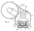
- Fig. 4 is an end cross-sectional view taken along line 4-4 of Fig. 3, showing the connection of an active electrode assembly
- Fig. 5 is an end view of the active electrode assembly of Fig. 3.
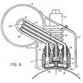
- Fig. 6 is an end cross-sectional view taken along line 6-6 of Fig. 3, showing air and gas supply lines.
- a multimode treater station includes a circular cylindrical roller electrode 10 and one or more active electrode assemblies 12 (shown in Fig. 2 with two).
- Each active electrode assembly 12 is mounted to a cylindrical header 14, preferably made of aluminum, and both the roller electrode 10 and header 14, are rotatably supported by a pair of spaced upright side assemblies 16 (one shown).
- a substrate in the form of a web 18 is fed into the treater past a pair of feed rollers 20 and around the roller electrode 10 causing it to rotate.
- the roller electrode 10 is a suitable metal, such as aluminum or steel, coated with a heat resistive dielectric material, such as ceramic.
- a hood 22 formed of a number of metal tubular members and panels, preferably made of a suitable sheet metal, that can be hinged up to allow access to the active electrode assemblies 12 and roller electrode 10.
- An exhaust tube 24 extending from inside the hood 22 draws ozone produced by the ionization process into a chemical treatment chamber as known in the art.
- each active electrode assembly 12 includes an electrode mounting block 26, preferably made of heat resistant, non-corrosive and non-conducting material, such as suitable phenolic.
- Two active electrodes 28 are mounted in recesses 27 running the length of the mounting block 26 so as to be spaced apart slightly and canted inwardly.
- Each active electrode 28 includes an elongated, preferably ceramic, electrode tube 30 having a generally rectangular cross-section. The electrode tube 30 extends across substantially the entire width of the treater.
- Each electrode tube 30 has non-conductive mounting tabs 33 spaced apart about ever 45,7 to 60,9 cm (18 to 24 inches) that are disposed in corresponding openings 32.
- the mounting tabs 32 have internally threaded bores for screws 34 that retain the active electrodes 28 to the mounting block 26.
- Each end of the electrode tubes 30 is closed by a non-conductive end cap (not shown).
- Each active electrode 28 also includes a metallic electrode strip 36, preferably made of a highly electrically conductive material, such as copper, lying along the bottom of the electrode tube 30.
- a metallic electrode strip 36 preferably made of a highly electrically conductive material, such as copper, lying along the bottom of the electrode tube 30.
- Each active electrode 28 has an active discharge surface 38 that faces the roller electrode 10.
- the active electrodes 28 are canted to follow the circular surface of the roller electrode 10 and to position the full width of the discharge surfaces 38 nearest to the surface of the roller electrode 10.
- the mounting block 26 is also formed to include a lengthwise channel 40 between the active electrodes 28 that is covered at the bottom by a lengthwise diffuser 42 so as to form a central chamber 43.
- the diffuser 42 forms the porous wall of the central chamber 43 and is preferably made of a heat resistant, porous material.
- the porous material has a porosity of 2-20 microns, such as a porous ceramic filter element AF6 having 6 micron pores commercially available from Refractron Technologies Corp. of Newark, New York.
- each header 14 supports an active electrode assembly 12 at bosses 44 fastened to the top of the mounting block 26.
- the mounting block 26 is fastened to two or more annular rib ceramic spacers 46 by screws 48.
- the ceramic spacers 46 are in turn fastened tow a lengthwise flange 50 attached to the header 14 by fasteners held in place by air gap adjustment nuts 52 at stainless steel blocks 53.
- This arrangement allows the height (and thereby the gap between the active electrode assemblies 12 and the roller electrode 10) to be adjusted by turning in and out the air gap adjustment nuts 52 as needed.
- the active electrode assemblies 12 are shrouded by an aluminum guard 55.
- two air tubes 54 run from fittings 56 disposed in bores in the mounting block 26 at inlet openings 58 at one end of the active electrodes 28.
- the air tubes 54 can be any suitable solid or flexible conduit for carrying air, such as polyethylene tubing.
- outlet openings 60 have fittings 62 disposed in corresponding bores in the mounting block 26 coupling exhaust tubes 64 extending from the active electrode assembly 12 into a Pyrex elbow 66 fit in an opening in the header 14.
- the exhaust lines 64 extend out of one or more openings at the end of the header 14.
- a gas supply line 68 runs from a fitting 70 in an inlet opening 72 at one end of the mounting block 26 leading to the chamber 43.
- the gas supply line 68 is preferably stainless steel tubing and/or flexible Teflon tubing.
- a second gas supply line (not shown) can run to a second inlet opening 74 at the opposite end of the mounting block 26 to provide more uniform distribution along the length of the active electrodes 28. If a second gas supply line is not used, the inlet opening 74 can be closed by a suitable non-conductive plug (not shown).
- the two air tubes 54 and the gas supply line 68 extend from the active electrode assembly 12 into a second elbow 76 in an opening near the opposite end of the header 14 where the air tubes 54 and gas supply line 68 exit the header 14.
- the air tubes 54 are suitably coupled to a compressed air source 78 such as a dedicated compressor or tap from a facility compressed air system.
- the gas supply line 68 runs to a flow meter 80 having a mixing valve coupled to one or more pressurized gas supply tanks 82, one of which contains helium.
- the additional tank(s) 82 can hold nitrogen, oxygen, argon, carbon dioxide and acetylene (or other suitable gas known in the art) selected according to the material to be treated.
- the air source 78 pumps approximately 2 CFM of compressed air through the air tubes 54 to the interior cavity of the active electrode tubes 30.
- the compressed air passes from the inlet opening 58 at one end though the length of the active electrode 28 and exits the outlet opening 60.
- the compressed air is relatively cool compared to the high temperatures of the active electrodes 28, which can operate at 100 degrees Celsius.
- the relatively cool air will carry away heat from the active electrodes 28 to cool the assembly 12.
- the cooling air passes by the entire surface area of the interior walls of the active electrodes 28, thereby maximizing heat transfer.
- the compressed air does not draw in contaminants from the.work area, which could otherwise be carbonized on the active electrodes 28 and cause arcing during use.
- the treater can be operated in three treatment modes: corona, chemical corona and plasma.
- the web material 18 is fed, at a certain line speed, through the treatment zone 81 near the discharge surfaces 38 of the active electrodes 28.
- the gas supply is stopped at the flow meter 80 so that no gas is present at the treatment zone.
- Compressed air can be passed through the gas supply line 68, by opening the valve 86 (shown in Fig. 2), to force air past the outside the active electrodes 28 through the gap between the active electrodes 28 beneath the diffuser 42. Doing so provides further cooling of the active electrodes 28, which is particularly beneficial to reduce the elevated temperatures in this treatment mode caused by the higher energy requirements of ionizing air. No contaminants are introduced because air is forced out away from the active electrodes 28 and because of the low volume and velocity of the compressed air employed.
- the energy requirements for the active electrodes 28 depend upon factors such as the type and width of the material being treated as well as the line speed of the process. Generally, the active electrodes 28 operate at 15-30 kHz and 10 kV when corona treating a 152,4 cm (60 inch) polymer web. Corona treatment provides a suitable macroscopic smoothing of the material surface and increase in surface tension for standard labeling, inking and lamination applications.
- the treatment level can be improved somewhat by operating the treater in the chemical corona mode in which gas is infused into the treatment zone and then ionized by the active electrodes 28. This is done by operating the flow meter 80 to send gas from a supply tank 84 through the gas supply line 68 into the chamber 43. In this mode, valve 86 is closed so that air is not passed through the gas line 68.
- the gas in the chamber 43 is uniformly distributed along the length of the active electrodes 28 by the diffuser 42.
- the gas is selected according to the material being treated as known in the art; for example, nitrogen is commonly used for treatment of polypropylene webs. A suitable mixture of gases may also be infused into the treatment zone.
- the active electrodes 28 in this mode operate under approximately the same input parameters as in the no gas corona mode mentioned above.
- the infusion of nitrogen may also work to reduce the production of ozone during the ionization process, thereby potentially reducing the air removal volume requirements of the exhaust system.
- the infusion of gaseous nitrogen into the corona may reduce the amount of power needed to produce a given treatment level since it is easier to ionize than air.
- the flow meter 80 is adjusted to pass helium to the treatment zone so that when ionized, plasma is formed in the treatment zone 81. It has been found that the helium content of the ionized gas at the treatment zone can be as low as 80 percent helium for plasma to form.
- atmospheric plasma treatment often referred to as "glow discharge plasma” provides an enhance treatment at lower energy requirements, without the formation of potentially damaging "streamers" that can occur in corona treatments. Materials with surfaces treated with plasma can be nearly homogenous. Consequently, although suitable for use for conventional polymer, foil and paper applications, plasma treating is preferred for applications requiring more uniform and enhanced treatment, such as photographic processing.
- the active electrodes 28 When the treater is in the plasma mode, the active electrodes 28 operate at approximately 50-100 kHz and 2-6 kV, again depending on the properties of the material being treated.
- the power supply includes a second transformer, among other things, having a higher turns ratio, approximately 2 to 1 over that used for corona and chemical corona treating.
- the treatment level is determined in part by the amount of electrical power applied. Generally, applying more electrical power will increase the treatment level. However, atmospheric plasma treating will provide approximately the same treatment level as corona treating, with enhanced uniformity and at a lower energy.
- the treatment zone 81 (the gap between the active electrodes 28 and the roller electrode 10) can be increased from approximately 0,15 cm (0.06 inches) for corona treating to about 0,95 cm (0. 375 inches), thereby significantly expanding the range of material thickness that can be treated.
- the invention provides a treater that can be operated in any one of three treatment modes by simply controlling the flow of gas to the active electrodes.
- the treater mode can be selected according to the application.
- the treater can be run in corona mode for low precision applications such as laminating polyolefin material or in chemical corona mode for enhanced treatment of polypropylenes.
- the treater can be operated in plasma mode for treating Teflon® or in high precision applications such as photographic processing or other applications where optical distortion is particularly undesirable.
- the conversion can be quickly and easily accomplished by operating the flow meter to change the type of gas flowing to the treatment zone or to stop gas flow altogether and selecting the proper power parameters from the power supply 37.
- the treater of the present invention can be sufficiently cooled without introducing contaminants into the electrode assembly. This is accomplished by using hollow active electrodes and circulating compressed air therethrough to transfer thermal energy from the active electrodes to the passing air. In corona mode, compressed air can be pumped through the gas line past the exterior surfaces of the active electrodes for further cooling.
- the active electrodes could be cooled by pumping a liquid coolant, such as water, from a pressurized source through conduit running through the tubular body of the active electrodes.
- a liquid coolant such as water
Landscapes
- Physics & Mathematics (AREA)
- Engineering & Computer Science (AREA)
- Plasma & Fusion (AREA)
- Health & Medical Sciences (AREA)
- Toxicology (AREA)
- Physical Or Chemical Processes And Apparatus (AREA)
- Treatments Of Macromolecular Shaped Articles (AREA)
- Treatment Of Fiber Materials (AREA)
- Central Air Conditioning (AREA)
Claims (12)
- Oberflächenbehandlungsvorrichtung, aufweisend:Eine Rollenelektrode (10), die zur Aufnahme von Flachmaterial (18) angeordnet ist, das über seine Außenseite läuft; eine aktive Elektrode (28), die sich entlang der Richtung der Rollenelektrode (10) erstreckt und eine Entladeoberfläche (38) aufweist, die von der Rollenelektrode (10) beabstandet ist, um dazwischen eine Behandlungszone (81) festzulegen;eine Stromversorgung (37), von der ein Anschluss mit der Rollenelektrode (10) und ein weiterer Anschluss mit der aktiven Elektrode (28) verbunden ist, um Gas in der Behandlungszone (81) zu ionisieren; undeine Versorgungsleitung (68), die mit einer Gasversorgung zum Leiten von Gas zu der Behandlungszone (81) verbindbar ist,dadurch gekennzeichnet, dass
die Versorgungsleitung (68) wahlweise mit einer Luftquelle (78) und einer Gasquelle (84) verbindbar ist, so dass die Behandlungsvorrichtung wahlweise in einer Koronabehandlungsbetriebsart und einer Plasmabehandlungsbetriebsart betrieben werden kann. - Behandlungsvorrichtung nach Anspruch 1, wobei die Versorgungsleitung (68) wahlweise mit einer Quelle (84) eines Gases verbindbar ist, das kein Plasma bildet, wenn es ionisiert wird, so dass die Behandlungsvorrichtung wahlweise in einer chemischen Koronabehandlung betrieben werden kann.
- Behandlungsvorrichtung nach Anspruch 1 oder 2, wobei ein Kühlsystem mit dem Einlassanschluss (58) der aktiven Elektrode (28) verbunden ist, um Luft relativ niedriger Temperatur in die Elektrode zu leiten, und
wobei das Kühlsystem aufweist:Eine Quelle für komprimierte Luft, undeine Leitung, die sich von dem Einlassanschluss (58) der aktiven Elektrode (28) ausgehend erstreckt und mit der Luftquelle verbindbar ist. - Behandlungsvorrichtung nach Anspruch 3, wobei der Einlassanschluss (58) und der Auslassanschluss (60) an gegenüberliegenden Enden der aktiven Elektrode (28) vorgesehen sind, und wobei das Kühlsystem außerdem eine mit dem Auslassanschluss (60) verbundene Auslassleitung aufweist.
- Behandlungsvorrichtung nach einem der vorangehenden Ansprüche, außerdem aufweisend eine zweite aktive Elektrode (28), die mit der Stromversorgung (37) verbunden und eine zur Rollenelektrode (10) weisende Entladeoberfläche aufweist, wobei die zweite aktive Elektrode (28) in Nebeneinanderlage zu der ersten aktiven Elektrode (28) ausgerichtet ist, um dazwischen eine Längskammer (43) festzulegen.
- Behandlungsvorrichtung nach Anspruch 5, wobei die Versorgungsleitung in die Längskammer (43) mündet und mit einem Gasversorgungstank verbindbar ist, um Gas durch die Kammer (43) zu der Entladeoberfläche (38) zwangsweise zu überführen.
- Behandlungsvorrichtung nach Anspruch 6, wobei das Gas aus der Gruppe ausgewählt ist, die aus Helium, Sauerstoff, Stickstoff, Argon, Acetylen, Kohlendioxid und Kombinationen hieraus besteht.
- Behandlungsvorrichtung nach Anspruch 7, außerdem aufweisend einen Diffusor (42), der sich zwischen den ersten und zweiten aktiven Elektroden (28) erstreckt und eine Bodenwand der Kammer (43) festlegt.
- Behandlungsvorrichtung nach Anspruch 7 oder 8, wobei das Gas Helium enthält, das in der Behandlungszone (81) ein Plasma bildet, wenn die aktive Elektrode (28) erregt bzw. mit Strom versorgt ist.
- Behandlungsvorrichtung nach Anspruch 8 oder 9, wobei der Diffusor (42) ein poröser Keramikstreifen ist.
- Behandlungsvorrichtung nach Anspruch 9 wobei die Gasströmung zu der Behandlungszone (81) zumindest 80 % Helium aufweist.
- Behandlungsvorrichtung nach Anspruch 5, wobei die ersten und zweiten aktiven Elektroden (28) einen rohrförmigen Körper aufweisen, die einen Metallstreifen (36) tragen, der benachbart zur Entladeoberfläche (38) angeordnet ist, und wobei die Elektroden jeweils einen Einlassanschluss (58) und einen Auslassanschluss (60) in Verbindung mit einem inneren Hohlraum des rohrförmigen Körpers aufweisen.
Applications Claiming Priority (3)
| Application Number | Priority Date | Filing Date | Title |
|---|---|---|---|
| US09/783,628 US6429595B1 (en) | 2001-02-14 | 2001-02-14 | Multi-mode treater with internal air cooling system |
| US783628 | 2001-02-14 | ||
| PCT/US2002/003554 WO2002065603A2 (en) | 2001-02-14 | 2002-02-06 | Multi-mode treater with internal air cooling system |
Publications (2)
| Publication Number | Publication Date |
|---|---|
| EP1360748A2 EP1360748A2 (de) | 2003-11-12 |
| EP1360748B1 true EP1360748B1 (de) | 2007-12-19 |
Family
ID=25129909
Family Applications (1)
| Application Number | Title | Priority Date | Filing Date |
|---|---|---|---|
| EP02703351A Expired - Lifetime EP1360748B1 (de) | 2001-02-14 | 2002-02-06 | Multimode-behandlungsvorrichtung mit luftkühlungssystem |
Country Status (5)
| Country | Link |
|---|---|
| US (1) | US6429595B1 (de) |
| EP (1) | EP1360748B1 (de) |
| AT (1) | ATE381800T1 (de) |
| DE (1) | DE60224166T2 (de) |
| WO (1) | WO2002065603A2 (de) |
Families Citing this family (19)
| Publication number | Priority date | Publication date | Assignee | Title |
|---|---|---|---|---|
| WO2003011967A1 (en) * | 2001-07-27 | 2003-02-13 | Tokuyama Corporation | Curable composition, cured article obtained therefrom, and photochromic optical material and process for producing the same |
| US6815246B2 (en) * | 2003-02-13 | 2004-11-09 | Rwe Schott Solar Inc. | Surface modification of silicon nitride for thick film silver metallization of solar cell |
| US7220462B2 (en) * | 2004-04-27 | 2007-05-22 | Praxair Technology, Inc. | Method and electrode assembly for non-equilibrium plasma treatment |
| US20050235915A1 (en) * | 2004-04-27 | 2005-10-27 | Ho Yeu-Chuan S | Plasma surface treatment electrode assembly and arrangement |
| KR100737755B1 (ko) * | 2006-08-10 | 2007-07-10 | 세메스 주식회사 | 플라스마 생성유닛 및 이를 구비하는 기판처리장치와기판처리방법 |
| WO2009036163A1 (en) * | 2007-09-11 | 2009-03-19 | Xtreme Ads Limited | Roller spark gap |
| DK2210321T3 (en) * | 2007-11-08 | 2015-08-31 | Enercon Ind Corp | Atmospheric processing unit with rolling limited discharge chamber |
| US9296924B2 (en) * | 2008-07-01 | 2016-03-29 | Firestone Building Products Company, Llc | Static dissipative release liner |
| EP2180768A1 (de) * | 2008-10-23 | 2010-04-28 | TNO Nederlandse Organisatie voor Toegepast Wetenschappelijk Onderzoek | Vorrichtung und Verfahren zur Behandlung eines Objekts |
| US9309619B2 (en) * | 2011-06-28 | 2016-04-12 | Mtix Ltd. | Method and apparatus for surface treatment of materials utilizing multiple combined energy sources |
| EP2574446B1 (de) * | 2011-09-30 | 2014-06-11 | Softal Corona & Plasma GmbH | Verfahren und Vorrichtung zur Beeinflussung von Oberflächeneigenschaften von Kunststofffilmen oder Metallfolien |
| US9126362B2 (en) | 2012-01-06 | 2015-09-08 | Daniel Brian Tan | Apparatus and method for corona treating film for self opening bags |
| WO2013103355A1 (en) * | 2012-01-06 | 2013-07-11 | Tan Daniel Brian | Apparatus and method for corona treating film for self opening bags |
| EP3054032B1 (de) * | 2015-02-09 | 2017-08-23 | Coating Plasma Industrie | Installation zur Filmabscheidung auf und/oder zur Modifikation der Oberfläche eines sich bewegenden Substrats |
| JP6183870B1 (ja) * | 2016-05-31 | 2017-08-23 | 春日電機株式会社 | 表面改質装置 |
| US9831070B1 (en) | 2017-06-15 | 2017-11-28 | Enercon Industries Corporation | Surface treater with expansion electrode arrangement |
| EP3666819B1 (de) * | 2017-08-07 | 2025-07-23 | Kasuga Denki, Inc. | Oberflächenmodifizierungsvorrichtung |
| EP3706519A1 (de) * | 2019-03-08 | 2020-09-09 | FGM Fritz Gradert Maschinenbau GmbH + Co. KG | Elektrode und vorrichtung zur korona-behandlung von oberflächen |
| US12338918B2 (en) | 2023-05-05 | 2025-06-24 | Enercon Industries Corporation | Roll end air fitting adapter and method of using same |
Family Cites Families (14)
| Publication number | Priority date | Publication date | Assignee | Title |
|---|---|---|---|---|
| US3409537A (en) | 1965-12-07 | 1968-11-05 | Milliken Tetra Pak | Apparatus for treating polymeric film in an electrostatic field having an adjustable electrode |
| DE2427933C2 (de) * | 1974-06-10 | 1983-08-04 | Klaus 4803 Steinhagen Kalwar | Statische Messerelektrode zum Behandeln von elektrisch leitenden Werkstoffen mit Coronaentladungen |
| US4028551A (en) * | 1975-10-17 | 1977-06-07 | Champion International Corporation | Apparatus and method for corona discharge priming a dielectric web |
| US4575329A (en) * | 1984-01-09 | 1986-03-11 | Andreas Ahlbrandt | Electrode element for corona treater |
| US4556544A (en) | 1984-05-17 | 1985-12-03 | Andreas Ahlbrandt | Retract mechanism for corona treater station |
| US5194291A (en) * | 1991-04-22 | 1993-03-16 | General Atomics | Corona discharge treatment |
| US5281174A (en) | 1992-11-12 | 1994-01-25 | Pillar Technologies | Corona treater high voltage plug-in |
| US5293043A (en) | 1992-12-24 | 1994-03-08 | Pillar Technologies | Electrode assembly for a corona tester |
| US5456972A (en) | 1993-05-28 | 1995-10-10 | The University Of Tennessee Research Corporation | Method and apparatus for glow discharge plasma treatment of polymer materials at atmospheric pressure |
| US5437844A (en) | 1993-10-25 | 1995-08-01 | Pillar Technologies, Inc. | Corona treater electrode cooling system |
| US5789145A (en) | 1996-07-23 | 1998-08-04 | Eastman Kodak Company | Atmospheric pressure glow discharge treatment of base material for photographic applications |
| DE19713127C1 (de) * | 1997-03-27 | 1998-11-12 | Brueckner Maschbau | Coronaelektroden-Anordnung |
| US6106659A (en) * | 1997-07-14 | 2000-08-22 | The University Of Tennessee Research Corporation | Treater systems and methods for generating moderate-to-high-pressure plasma discharges for treating materials and related treated materials |
| US6118218A (en) | 1999-02-01 | 2000-09-12 | Sigma Technologies International, Inc. | Steady-state glow-discharge plasma at atmospheric pressure |
-
2001
- 2001-02-14 US US09/783,628 patent/US6429595B1/en not_active Expired - Lifetime
-
2002
- 2002-02-06 DE DE60224166T patent/DE60224166T2/de not_active Expired - Lifetime
- 2002-02-06 AT AT02703351T patent/ATE381800T1/de not_active IP Right Cessation
- 2002-02-06 WO PCT/US2002/003554 patent/WO2002065603A2/en not_active Ceased
- 2002-02-06 EP EP02703351A patent/EP1360748B1/de not_active Expired - Lifetime
Also Published As
| Publication number | Publication date |
|---|---|
| WO2002065603A2 (en) | 2002-08-22 |
| EP1360748A2 (de) | 2003-11-12 |
| ATE381800T1 (de) | 2008-01-15 |
| DE60224166T2 (de) | 2008-12-11 |
| WO2002065603A3 (en) | 2002-10-10 |
| US6429595B1 (en) | 2002-08-06 |
| US20020109470A1 (en) | 2002-08-15 |
| DE60224166D1 (de) | 2008-01-31 |
Similar Documents
| Publication | Publication Date | Title |
|---|---|---|
| US6429595B1 (en) | Multi-mode treater with internal air cooling system | |
| US8709351B2 (en) | Atmospheric treater with roller confined discharge chamber | |
| US5387842A (en) | Steady-state, glow discharge plasma | |
| TWI861060B (zh) | 基材處理和/或塗覆系統 | |
| CN1109130C (zh) | 在移动基材上沉积富碳涂层的方法和装置 | |
| EP0778902B1 (de) | Verfahren und vorrichtung zum plasmaspritzen | |
| US7067405B2 (en) | Atmospheric glow discharge with concurrent coating deposition | |
| US20100112235A1 (en) | Method for treating plasma under continuous atmospheric pressure of work pieces, in particular, material plates or strips | |
| CN1997773A (zh) | 等离子清洗附有机物质的材料表面的方法和实现该方法的装置 | |
| US5743966A (en) | Unwinding of plastic film in the presence of a plasma | |
| WO1993005890A1 (en) | Pulsed discharge surface treatment apparatus and process | |
| US6146503A (en) | Method and apparatus for dry surface treatment of an object | |
| CN113117109B (zh) | 阵列射流等离子体快速消杀表面病原微生物系统与方法 | |
| US20220336188A1 (en) | Plasma treatment system and plasma treatment method | |
| EP3163983A1 (de) | Vorrichtung zur plasmabehandlung mit indirektem atmosphärischem druck | |
| JP3662621B2 (ja) | 誘導プラズマの発生方法および装置 | |
| JP4630874B2 (ja) | 大気圧大面積グロープラズマ発生装置 | |
| US8778080B2 (en) | Apparatus for double-plasma graft polymerization at atmospheric pressure | |
| US20090045168A1 (en) | Surface Treater for Elongated Articles | |
| EP3666819B1 (de) | Oberflächenmodifizierungsvorrichtung | |
| KR100275344B1 (ko) | 여기 혹은 불안전한 상태의 기체 분자를 형성하는 장치 및 그 장치를 사용하는 기체 분자 생산 방법 | |
| EP1993330B1 (de) | Elektrode und Vorrichtung zur Erzeugung eines Atmosphärendruck-Plasmas | |
| KR100368052B1 (ko) | 플라즈마를 이용한 고분자막 연속중합장치 | |
| JP2003197396A (ja) | プラズマ放電装置 | |
| TWI916985B (zh) | 基材處理和/或塗覆系統 |
Legal Events
| Date | Code | Title | Description |
|---|---|---|---|
| PUAI | Public reference made under article 153(3) epc to a published international application that has entered the european phase |
Free format text: ORIGINAL CODE: 0009012 |
|
| 17P | Request for examination filed |
Effective date: 20030825 |
|
| AK | Designated contracting states |
Kind code of ref document: A2 Designated state(s): AT BE CH CY DE DK ES FI FR GB GR IE IT LI LU MC NL PT SE TR |
|
| 17Q | First examination report despatched |
Effective date: 20061115 |
|
| GRAP | Despatch of communication of intention to grant a patent |
Free format text: ORIGINAL CODE: EPIDOSNIGR1 |
|
| GRAS | Grant fee paid |
Free format text: ORIGINAL CODE: EPIDOSNIGR3 |
|
| GRAA | (expected) grant |
Free format text: ORIGINAL CODE: 0009210 |
|
| AK | Designated contracting states |
Kind code of ref document: B1 Designated state(s): AT BE CH CY DE DK ES FI FR GB GR IE IT LI LU MC NL PT SE TR |
|
| REG | Reference to a national code |
Ref country code: GB Ref legal event code: FG4D |
|
| REG | Reference to a national code |
Ref country code: IE Ref legal event code: FG4D |
|
| REG | Reference to a national code |
Ref country code: CH Ref legal event code: EP |
|
| REF | Corresponds to: |
Ref document number: 60224166 Country of ref document: DE Date of ref document: 20080131 Kind code of ref document: P |
|
| PG25 | Lapsed in a contracting state [announced via postgrant information from national office to epo] |
Ref country code: SE Free format text: LAPSE BECAUSE OF FAILURE TO SUBMIT A TRANSLATION OF THE DESCRIPTION OR TO PAY THE FEE WITHIN THE PRESCRIBED TIME-LIMIT Effective date: 20080319 Ref country code: LI Free format text: LAPSE BECAUSE OF FAILURE TO SUBMIT A TRANSLATION OF THE DESCRIPTION OR TO PAY THE FEE WITHIN THE PRESCRIBED TIME-LIMIT Effective date: 20071219 Ref country code: CH Free format text: LAPSE BECAUSE OF FAILURE TO SUBMIT A TRANSLATION OF THE DESCRIPTION OR TO PAY THE FEE WITHIN THE PRESCRIBED TIME-LIMIT Effective date: 20071219 |
|
| PG25 | Lapsed in a contracting state [announced via postgrant information from national office to epo] |
Ref country code: FI Free format text: LAPSE BECAUSE OF FAILURE TO SUBMIT A TRANSLATION OF THE DESCRIPTION OR TO PAY THE FEE WITHIN THE PRESCRIBED TIME-LIMIT Effective date: 20071219 Ref country code: NL Free format text: LAPSE BECAUSE OF FAILURE TO SUBMIT A TRANSLATION OF THE DESCRIPTION OR TO PAY THE FEE WITHIN THE PRESCRIBED TIME-LIMIT Effective date: 20071219 |
|
| NLV1 | Nl: lapsed or annulled due to failure to fulfill the requirements of art. 29p and 29m of the patents act | ||
| REG | Reference to a national code |
Ref country code: CH Ref legal event code: PL |
|
| PG25 | Lapsed in a contracting state [announced via postgrant information from national office to epo] |
Ref country code: AT Free format text: LAPSE BECAUSE OF FAILURE TO SUBMIT A TRANSLATION OF THE DESCRIPTION OR TO PAY THE FEE WITHIN THE PRESCRIBED TIME-LIMIT Effective date: 20071219 |
|
| PG25 | Lapsed in a contracting state [announced via postgrant information from national office to epo] |
Ref country code: ES Free format text: LAPSE BECAUSE OF FAILURE TO SUBMIT A TRANSLATION OF THE DESCRIPTION OR TO PAY THE FEE WITHIN THE PRESCRIBED TIME-LIMIT Effective date: 20080330 |
|
| PG25 | Lapsed in a contracting state [announced via postgrant information from national office to epo] |
Ref country code: PT Free format text: LAPSE BECAUSE OF FAILURE TO SUBMIT A TRANSLATION OF THE DESCRIPTION OR TO PAY THE FEE WITHIN THE PRESCRIBED TIME-LIMIT Effective date: 20080519 |
|
| EN | Fr: translation not filed | ||
| PLBE | No opposition filed within time limit |
Free format text: ORIGINAL CODE: 0009261 |
|
| STAA | Information on the status of an ep patent application or granted ep patent |
Free format text: STATUS: NO OPPOSITION FILED WITHIN TIME LIMIT |
|
| PG25 | Lapsed in a contracting state [announced via postgrant information from national office to epo] |
Ref country code: DK Free format text: LAPSE BECAUSE OF FAILURE TO SUBMIT A TRANSLATION OF THE DESCRIPTION OR TO PAY THE FEE WITHIN THE PRESCRIBED TIME-LIMIT Effective date: 20071219 Ref country code: MC Free format text: LAPSE BECAUSE OF NON-PAYMENT OF DUE FEES Effective date: 20080228 |
|
| 26N | No opposition filed |
Effective date: 20080922 |
|
| PG25 | Lapsed in a contracting state [announced via postgrant information from national office to epo] |
Ref country code: IE Free format text: LAPSE BECAUSE OF NON-PAYMENT OF DUE FEES Effective date: 20080206 Ref country code: GR Free format text: LAPSE BECAUSE OF FAILURE TO SUBMIT A TRANSLATION OF THE DESCRIPTION OR TO PAY THE FEE WITHIN THE PRESCRIBED TIME-LIMIT Effective date: 20080320 |
|
| PG25 | Lapsed in a contracting state [announced via postgrant information from national office to epo] |
Ref country code: FR Free format text: LAPSE BECAUSE OF FAILURE TO SUBMIT A TRANSLATION OF THE DESCRIPTION OR TO PAY THE FEE WITHIN THE PRESCRIBED TIME-LIMIT Effective date: 20081010 |
|
| PG25 | Lapsed in a contracting state [announced via postgrant information from national office to epo] |
Ref country code: CY Free format text: LAPSE BECAUSE OF FAILURE TO SUBMIT A TRANSLATION OF THE DESCRIPTION OR TO PAY THE FEE WITHIN THE PRESCRIBED TIME-LIMIT Effective date: 20071219 |
|
| PG25 | Lapsed in a contracting state [announced via postgrant information from national office to epo] |
Ref country code: LU Free format text: LAPSE BECAUSE OF NON-PAYMENT OF DUE FEES Effective date: 20080206 |
|
| PG25 | Lapsed in a contracting state [announced via postgrant information from national office to epo] |
Ref country code: TR Free format text: LAPSE BECAUSE OF FAILURE TO SUBMIT A TRANSLATION OF THE DESCRIPTION OR TO PAY THE FEE WITHIN THE PRESCRIBED TIME-LIMIT Effective date: 20071219 |
|
| PGFP | Annual fee paid to national office [announced via postgrant information from national office to epo] |
Ref country code: DE Payment date: 20140207 Year of fee payment: 13 |
|
| PGFP | Annual fee paid to national office [announced via postgrant information from national office to epo] |
Ref country code: IT Payment date: 20140225 Year of fee payment: 13 |
|
| PGFP | Annual fee paid to national office [announced via postgrant information from national office to epo] |
Ref country code: BE Payment date: 20140303 Year of fee payment: 13 |
|
| PG25 | Lapsed in a contracting state [announced via postgrant information from national office to epo] |
Ref country code: BE Free format text: LAPSE BECAUSE OF NON-PAYMENT OF DUE FEES Effective date: 20150228 |
|
| REG | Reference to a national code |
Ref country code: DE Ref legal event code: R082 Ref document number: 60224166 Country of ref document: DE |
|
| REG | Reference to a national code |
Ref country code: DE Ref legal event code: R119 Ref document number: 60224166 Country of ref document: DE |
|
| PG25 | Lapsed in a contracting state [announced via postgrant information from national office to epo] |
Ref country code: IT Free format text: LAPSE BECAUSE OF NON-PAYMENT OF DUE FEES Effective date: 20150206 |
|
| PG25 | Lapsed in a contracting state [announced via postgrant information from national office to epo] |
Ref country code: DE Free format text: LAPSE BECAUSE OF NON-PAYMENT OF DUE FEES Effective date: 20150901 |
|
| GBPC | Gb: european patent ceased through non-payment of renewal fee |
Effective date: 20170206 |
|
| PG25 | Lapsed in a contracting state [announced via postgrant information from national office to epo] |
Ref country code: GB Free format text: LAPSE BECAUSE OF NON-PAYMENT OF DUE FEES Effective date: 20170206 |
|
| REG | Reference to a national code |
Ref country code: GB Ref legal event code: S28 Free format text: APPLICATION FILED |
|
| REG | Reference to a national code |
Ref country code: GB Ref legal event code: S28 Free format text: RESTORATION ALLOWED Effective date: 20180611 |
|
| PGFP | Annual fee paid to national office [announced via postgrant information from national office to epo] |
Ref country code: GB Payment date: 20210225 Year of fee payment: 20 |
|
| REG | Reference to a national code |
Ref country code: GB Ref legal event code: PE20 Expiry date: 20220205 |
|
| PG25 | Lapsed in a contracting state [announced via postgrant information from national office to epo] |
Ref country code: GB Free format text: LAPSE BECAUSE OF EXPIRATION OF PROTECTION Effective date: 20220205 |