EP1359474A1 - Mounting structure of a process cartridge and an electrophotographic image forming apparatus - Google Patents
Mounting structure of a process cartridge and an electrophotographic image forming apparatus Download PDFInfo
- Publication number
- EP1359474A1 EP1359474A1 EP03008922A EP03008922A EP1359474A1 EP 1359474 A1 EP1359474 A1 EP 1359474A1 EP 03008922 A EP03008922 A EP 03008922A EP 03008922 A EP03008922 A EP 03008922A EP 1359474 A1 EP1359474 A1 EP 1359474A1
- Authority
- EP
- European Patent Office
- Prior art keywords
- main assembly
- process cartridge
- cartridge
- photosensitive drum
- contact portion
- Prior art date
- Legal status (The legal status is an assumption and is not a legal conclusion. Google has not performed a legal analysis and makes no representation as to the accuracy of the status listed.)
- Withdrawn
Links
- 238000000034 method Methods 0.000 title claims abstract description 337
- 230000008569 process Effects 0.000 title claims abstract description 330
- 230000008878 coupling Effects 0.000 claims abstract description 70
- 238000010168 coupling process Methods 0.000 claims abstract description 70
- 238000005859 coupling reaction Methods 0.000 claims abstract description 70
- 238000012546 transfer Methods 0.000 claims description 34
- 239000000463 material Substances 0.000 claims description 13
- 238000011161 development Methods 0.000 description 70
- 230000002093 peripheral effect Effects 0.000 description 48
- 238000004140 cleaning Methods 0.000 description 28
- 239000002245 particle Substances 0.000 description 28
- 238000007789 sealing Methods 0.000 description 12
- 230000006835 compression Effects 0.000 description 10
- 238000007906 compression Methods 0.000 description 10
- 230000007246 mechanism Effects 0.000 description 10
- 125000006850 spacer group Chemical group 0.000 description 9
- 230000015572 biosynthetic process Effects 0.000 description 7
- XLOMVQKBTHCTTD-UHFFFAOYSA-N Zinc monoxide Chemical compound [Zn]=O XLOMVQKBTHCTTD-UHFFFAOYSA-N 0.000 description 6
- 238000012545 processing Methods 0.000 description 6
- 239000000126 substance Substances 0.000 description 6
- 239000004745 nonwoven fabric Substances 0.000 description 5
- 229920002635 polyurethane Polymers 0.000 description 5
- 239000004814 polyurethane Substances 0.000 description 5
- 230000001276 controlling effect Effects 0.000 description 4
- 239000004721 Polyphenylene oxide Substances 0.000 description 3
- XECAHXYUAAWDEL-UHFFFAOYSA-N acrylonitrile butadiene styrene Chemical compound C=CC=C.C=CC#N.C=CC1=CC=CC=C1 XECAHXYUAAWDEL-UHFFFAOYSA-N 0.000 description 3
- 229920000122 acrylonitrile butadiene styrene Polymers 0.000 description 3
- 239000004676 acrylonitrile butadiene styrene Substances 0.000 description 3
- 238000005054 agglomeration Methods 0.000 description 3
- 230000002776 aggregation Effects 0.000 description 3
- 230000004048 modification Effects 0.000 description 3
- 238000012986 modification Methods 0.000 description 3
- 230000003287 optical effect Effects 0.000 description 3
- 229920003023 plastic Polymers 0.000 description 3
- 239000004033 plastic Substances 0.000 description 3
- 239000011787 zinc oxide Substances 0.000 description 3
- PPBRXRYQALVLMV-UHFFFAOYSA-N Styrene Chemical compound C=CC1=CC=CC=C1 PPBRXRYQALVLMV-UHFFFAOYSA-N 0.000 description 2
- 239000002390 adhesive tape Substances 0.000 description 2
- XAGFODPZIPBFFR-UHFFFAOYSA-N aluminium Chemical compound [Al] XAGFODPZIPBFFR-UHFFFAOYSA-N 0.000 description 2
- 229910052782 aluminium Inorganic materials 0.000 description 2
- 239000013039 cover film Substances 0.000 description 2
- 238000007598 dipping method Methods 0.000 description 2
- 238000007667 floating Methods 0.000 description 2
- 229920005669 high impact polystyrene Polymers 0.000 description 2
- 239000004797 high-impact polystyrene Substances 0.000 description 2
- 230000006872 improvement Effects 0.000 description 2
- 238000005259 measurement Methods 0.000 description 2
- 230000035515 penetration Effects 0.000 description 2
- -1 polyethylene Polymers 0.000 description 2
- 229920001955 polyphenylene ether Polymers 0.000 description 2
- 229920006380 polyphenylene oxide Polymers 0.000 description 2
- 238000003825 pressing Methods 0.000 description 2
- 239000011347 resin Substances 0.000 description 2
- 229920005989 resin Polymers 0.000 description 2
- 238000003860 storage Methods 0.000 description 2
- 229910000838 Al alloy Inorganic materials 0.000 description 1
- JOYRKODLDBILNP-UHFFFAOYSA-N Ethyl urethane Chemical compound CCOC(N)=O JOYRKODLDBILNP-UHFFFAOYSA-N 0.000 description 1
- 239000004698 Polyethylene Substances 0.000 description 1
- 239000004743 Polypropylene Substances 0.000 description 1
- 239000004793 Polystyrene Substances 0.000 description 1
- BUGBHKTXTAQXES-UHFFFAOYSA-N Selenium Chemical compound [Se] BUGBHKTXTAQXES-UHFFFAOYSA-N 0.000 description 1
- GWEVSGVZZGPLCZ-UHFFFAOYSA-N Titan oxide Chemical compound O=[Ti]=O GWEVSGVZZGPLCZ-UHFFFAOYSA-N 0.000 description 1
- 229910021417 amorphous silicon Inorganic materials 0.000 description 1
- 238000005452 bending Methods 0.000 description 1
- NTXGQCSETZTARF-UHFFFAOYSA-N buta-1,3-diene;prop-2-enenitrile Chemical compound C=CC=C.C=CC#N NTXGQCSETZTARF-UHFFFAOYSA-N 0.000 description 1
- 238000011109 contamination Methods 0.000 description 1
- 229920001577 copolymer Polymers 0.000 description 1
- 230000007547 defect Effects 0.000 description 1
- 230000008021 deposition Effects 0.000 description 1
- 238000009826 distribution Methods 0.000 description 1
- 230000000694 effects Effects 0.000 description 1
- 238000000605 extraction Methods 0.000 description 1
- 238000010422 painting Methods 0.000 description 1
- 230000035699 permeability Effects 0.000 description 1
- 229920002587 poly(1,3-butadiene) polymer Polymers 0.000 description 1
- 229920000515 polycarbonate Polymers 0.000 description 1
- 239000004417 polycarbonate Substances 0.000 description 1
- 229920000573 polyethylene Polymers 0.000 description 1
- 229920013636 polyphenyl ether polymer Polymers 0.000 description 1
- 229920001155 polypropylene Polymers 0.000 description 1
- 229920002223 polystyrene Polymers 0.000 description 1
- 230000002265 prevention Effects 0.000 description 1
- 239000011164 primary particle Substances 0.000 description 1
- 230000001105 regulatory effect Effects 0.000 description 1
- 230000002787 reinforcement Effects 0.000 description 1
- 239000000565 sealant Substances 0.000 description 1
- 239000011163 secondary particle Substances 0.000 description 1
- 239000011669 selenium Substances 0.000 description 1
- 229910052711 selenium Inorganic materials 0.000 description 1
- OGIDPMRJRNCKJF-UHFFFAOYSA-N titanium oxide Inorganic materials [Ti]=O OGIDPMRJRNCKJF-UHFFFAOYSA-N 0.000 description 1
- 230000000007 visual effect Effects 0.000 description 1
Images















Classifications
-
- G—PHYSICS
- G03—PHOTOGRAPHY; CINEMATOGRAPHY; ANALOGOUS TECHNIQUES USING WAVES OTHER THAN OPTICAL WAVES; ELECTROGRAPHY; HOLOGRAPHY
- G03G—ELECTROGRAPHY; ELECTROPHOTOGRAPHY; MAGNETOGRAPHY
- G03G15/00—Apparatus for electrographic processes using a charge pattern
-
- G—PHYSICS
- G03—PHOTOGRAPHY; CINEMATOGRAPHY; ANALOGOUS TECHNIQUES USING WAVES OTHER THAN OPTICAL WAVES; ELECTROGRAPHY; HOLOGRAPHY
- G03G—ELECTROGRAPHY; ELECTROPHOTOGRAPHY; MAGNETOGRAPHY
- G03G21/00—Arrangements not provided for by groups G03G13/00 - G03G19/00, e.g. cleaning, elimination of residual charge
- G03G21/16—Mechanical means for facilitating the maintenance of the apparatus, e.g. modular arrangements
- G03G21/18—Mechanical means for facilitating the maintenance of the apparatus, e.g. modular arrangements using a processing cartridge, whereby the process cartridge comprises at least two image processing means in a single unit
- G03G21/1839—Means for handling the process cartridge in the apparatus body
- G03G21/1857—Means for handling the process cartridge in the apparatus body for transmitting mechanical drive power to the process cartridge, drive mechanisms, gears, couplings, braking mechanisms
- G03G21/186—Axial couplings
-
- G—PHYSICS
- G03—PHOTOGRAPHY; CINEMATOGRAPHY; ANALOGOUS TECHNIQUES USING WAVES OTHER THAN OPTICAL WAVES; ELECTROGRAPHY; HOLOGRAPHY
- G03B—APPARATUS OR ARRANGEMENTS FOR TAKING PHOTOGRAPHS OR FOR PROJECTING OR VIEWING THEM; APPARATUS OR ARRANGEMENTS EMPLOYING ANALOGOUS TECHNIQUES USING WAVES OTHER THAN OPTICAL WAVES; ACCESSORIES THEREFOR
- G03B21/00—Projectors or projection-type viewers; Accessories therefor
- G03B21/14—Details
- G03B21/18—Fire preventing or extinguishing
-
- G—PHYSICS
- G03—PHOTOGRAPHY; CINEMATOGRAPHY; ANALOGOUS TECHNIQUES USING WAVES OTHER THAN OPTICAL WAVES; ELECTROGRAPHY; HOLOGRAPHY
- G03G—ELECTROGRAPHY; ELECTROPHOTOGRAPHY; MAGNETOGRAPHY
- G03G21/00—Arrangements not provided for by groups G03G13/00 - G03G19/00, e.g. cleaning, elimination of residual charge
- G03G21/16—Mechanical means for facilitating the maintenance of the apparatus, e.g. modular arrangements
- G03G21/18—Mechanical means for facilitating the maintenance of the apparatus, e.g. modular arrangements using a processing cartridge, whereby the process cartridge comprises at least two image processing means in a single unit
- G03G21/1839—Means for handling the process cartridge in the apparatus body
- G03G21/1857—Means for handling the process cartridge in the apparatus body for transmitting mechanical drive power to the process cartridge, drive mechanisms, gears, couplings, braking mechanisms
- G03G21/1864—Means for handling the process cartridge in the apparatus body for transmitting mechanical drive power to the process cartridge, drive mechanisms, gears, couplings, braking mechanisms associated with a positioning function
-
- G—PHYSICS
- G03—PHOTOGRAPHY; CINEMATOGRAPHY; ANALOGOUS TECHNIQUES USING WAVES OTHER THAN OPTICAL WAVES; ELECTROGRAPHY; HOLOGRAPHY
- G03G—ELECTROGRAPHY; ELECTROPHOTOGRAPHY; MAGNETOGRAPHY
- G03G2221/00—Processes not provided for by group G03G2215/00, e.g. cleaning or residual charge elimination
- G03G2221/16—Mechanical means for facilitating the maintenance of the apparatus, e.g. modular arrangements and complete machine concepts
- G03G2221/18—Cartridge systems
- G03G2221/183—Process cartridge
- G03G2221/1884—Projections on process cartridge for guiding mounting thereof in main machine
Definitions
- the present invention relates to a process cartridge removably mountable in an electrophotographic image forming apparatus, and an electrophotographic image forming apparatus.
- an electrophotographic image forming apparatus means an apparatus which forms an image on recording medium with the use of an electrophotographic image forming method.
- Examples of an electrophotographic image forming apparatus include an electrophotographic copying machine, an electrophotographic printer (for example, laser printer, LED printer, etc.), a facsimile machine, a wordprocessor, a combination of two or more of the preceding apparatuses (multifunction printer, etc.), etc.
- a process cartridge means a cartridge in which a charging means, a developing means or a cleaning means, and an electrophotographic photoconductive member, are integrally disposed, and which is removably mountable in the main assembly of an image forming apparatus; a cartridge in which a minimum of one among a charging means, a developing means, and cleaning means, and an electrophotographic photoconductive member, are integrally disposed, and which is removably mountable in the main assembly of an image forming apparatus; or a cartridge in which a minimum of a developing apparatus and an electrophotographic photoconductive member are integrally disposed, and which is removably mountable in the main assembly of an image forming apparatus.
- a process cartridge system which has an electrophotographic photoconductive member, and a single or plurality of processing means which act on the electrophotographic photoconductive member, are integrally disposed in a cartridge removably mountable in the main assembly of an image forming apparatus has long been employed by an electrophotographic image forming apparatus which uses an electrophotographic image firming process.
- an apparatus can be maintained by a user him/herself; it is unnecessary to hire a service person.
- the employment of a cartridge system drastically improves the apparatus in operational efficiency. Therefore, a cartridge system has been widely used in the field of an image forming apparatus.
- Figure 31 shows a process cartridge CR
- Figure 32 shows a cartridge guide GL of the main assembly PR of an image forming apparatus
- Figure 33 shows an image forming apparatus employing the process cartridge CR.
- the process cartridge CR in order to guide the process cartridge CR and accurately position the process cartridge CR in the image forming apparatus main assembly PR when mounting the process cartridge CR into the image forming apparatus main assembly PR or removing it therefrom, the process cartridge CR is provided with a positioning boss CB, the axial line of which coincides with the axial line of the photoconductive drum, as an electrophotographic photoconductive member, in the process cartridge CR, whereas the image forming apparatus main assembly is provided with a process cartridge mounting guide GL, which guides the process cartridge CR by the positioning boss CB thereof.
- the present invention is a result of further technical development of the above described prior art.
- the primary object of the present invention is to provide a combination of a process cartridge and an electrophotographic image forming apparatus employing a process cartridge system, in which the cartridge is more reliably mounted into, or dismounted from, the main assembly of the image forming apparatus.
- Another object of the present invention is to provide a combination of a process cartridge and an electrophotographic image forming apparatus employing a process cartridge system, in which the process cartridge is more accurately positioned relative to the main assembly of the image forming apparatus when the process cartridge is mounted into the main assembly,
- Another object of the present invention is to provide a combination of a process cartridge and an electrophotographic image forming apparatus employing a process cartridge system, in which the process cartridge remain more stable when the process cartridge is mounted into the main assembly.
- Another object of the present invention is to provide:
- Another object of the prevent invention is to provide:
- the lengthwise direction of a process cartridge means the direction intersectional (roughly perpendicular) to the direction in which a process cartridge is mounted into, or removed from, the main assembly of an image forming apparatus. It is parallel to the surface of recording medium, and is intersectional (roughly perpendicular) to the direction in which the recording medium is conveyed.
- the right or left direction means the right or left direction of the recording medium as the recording medium is seen from the rear side in terms of the recording medium conveyance direction.
- top surface of a process cartridge means the surface of the process cartridge which will be on the top side after the proper mounting of the process cartridge in the main assembly of an image forming apparatus
- bottom surface of the process cartridge means the surface of the process cartridge which will be on the bottom side after the proper mounting of the process cartridge in the apparatus main assembly.
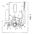
- Figure 1 shows one of the preferred embodiments of an electrophotographic image forming apparatus in accordance with the present invention.
- a process cartridge B shown in Figure 2 is removably mountable in this electrophotographic image forming apparatus.
- Figure 1 is a schematic drawing for describing the structure of this electrophotographic image forming apparatus, which is properly holding the process cartridge B in Figure 2.
- Figure 2 is a schematic drawing for describing the structure of the process cartridge B.
- the general structure of the prpcess cartridge B and the general structure of the electrophotographic image forming apparatus employing the process cartridge B will be first described. Then, the structure of the mechanism of the image forming apparatus main assembly for guiding the process cartridge B when the process cartridge B is mounted into, or removed from, the main assembly of the electrophotographic image forming apparatus will be described.
- the electrophotographic image forming apparatus A (which hereinafter will be referred to simply as “image forming apparatus”) in this embodiment is a laser beam printer, and has an electrophotographic photoconductive member 7 in the form of a drum (which hereinafter will be referred to simply as “photoconductive drum”), as an image bearing member, which comprises an aluminum cylinder, and a photoconductive layer, that is, a layer of organic photoconductive substance, coated on the entirety of the peripheral surface of the aluminum cylinder.
- a beam of light carrying image formation information is projected onto the photoconductive drum 7 from an optical system 1, forming a latent image on the photoconductive drum 7.
- This latent image is developed into a toner image with the use of developer (which hereinafter may be referred to as "toner").
- a single or plurality of sheets of recording medium 2 in the sheet feeder cassette 3a are fed one by one into the apparatus main assembly by the combination of a pickup roller 3b, and a pressing member 3c kept pressed against the pickup roller 3b, and are conveyed further inward by a conveying means 3f.
- the toner image formed on the photoconductive drum 7 in the process cartridge B is transferred onto the recording medium 2 by applying voltage to a transfer roller 4 as a transferring means. Then, the recording medium 2 is conveyed to a fixing means 5 by the conveying means 3f.
- the fixing means 5 comprises: a driving roller 5a, a heater 5b, a supporting member 5c, and a rotational fixing member 5d.
- the rotational fixing member 5d is a cylinder formed of sheet of a certain substance, and is supported by the supporting member 5c.
- the heater 5b is in the hollow of the rotational fixing member 5d.
- the fixing means 5 fixes the unfixed toner image on the recording medium 2 to the recording medium 2, by the application of heat and pressure to the recording medium 2 while the recording medium 2 is passed through the fixing means 5. After the fixation, the recording medium 2 is further conveyed and discharged into the delivery area 6, by a pair of discharge rollers 3d.
- the process cartridge B comprises an electrophotographic photoconductive member, and a minimum of one processing means.
- the processing means there are, for example, a charging means for charging the electrophotographic photoconductive member, and a developing means for developing a latent image formed on the electrophotographic member.
- the process cartridge B in this embodiment comprises the photoconductive drum 7, as an electrophotographic photoconductive drum, having a photoconductive layer, a charge roller 8 as a charging means, a developing means 10, and an exposure opening 9.
- the photoconductive drum 7 is rotated, the peripheral surface of the photoconductive drum 7 is uniformly charged by the application of voltage to the charge roller 8, and the uniformly charged portion of the peripheral surface of the photoconductive drum 7 is exposed to an optical image projected from the optical system 1, forming a latent image. Then, the latent image is developed by the developing means 10.
- the developing means 10 in this embodiment comprises a toner storage-developing means frame 10f1, a frame lid 10f2, a rotational toner conveyance roller 10b as a toner conveying means, a development roller 10d (in which a magnet 10c is stationarily disposed) as a rotational developing member, and a development blade 10e.
- the toner storage-developing means frame 10f1 and frame lid 10f2 are joined, creating a toner chamber (toner storage) 10a in which toner (magnetic single-component developer) is stored, and a development chamber 10i.
- the toner in the toner chamber 10a is sent out into the development chamber 10i through the opening (toner passage) 10k of the toner storage-developing means frame 10f1, by the toner conveyance roller 10b.
- the development roller 10d is rotated, and a layer of triboelectrically charged toner is formed on the peripheral surface of the rotating development roller 10d.
- the toner is transferred onto the peripheral surface of the photoconductive drum 7 from the toner layer on the development roller 10d, in the pattern of the latent image on the photoconductive drum 7, developing the latent image into a visual image, that is, a toner image.
- the toner image is transferred onto the recording medium 2 by the application of a voltage, opposite in polarity to the toner image, to a transfer roller 4.
- the transfer residual toner that is, the toner remaining on the photoconductive drum 7 after the toner image transfer, is recovered during the following rotational cycle of the photoconductive drum 7.
- the peripheral surface of the photoconductive drum 7 is charged by the charge roller 8 with the presence of the transfer residual toner on the peripheral surface of the photoconductive drum 7, and another latent image is formed on the peripheral surface of the photoconductive drum 7 by exposure, and then, the residual toner from the preceding rotational cycle of the photoconductive drum 7 is recovered by the fog prevention bias (difference Vback between the potential level of the DC voltage applied to the developing apparatus and the surface potential level of the photoconductive member) during the development of the latent image.
- a cleaning means such as a cleaning blade for removing the transfer residual toner on the photoconductive drum 7 is not provided.
- the process cartridge B which will be described in more detail later, is removably mounted into the cartridge mounting portion of the main portion, that is, the main assembly A0, of the image forming apparatus A, while being guided by the pair of guiding portions of the process cartridge B, which are located at the lengthwise ends of the process cartridge B, one for one.
- the process cartridge B comprises a drum holding frame 102, which is one of the main sections of the cartridge frame, and the toner storage-developing means frame 10f1, which constitutes another of the main sections of the cartridge frame.
- the drum holding frame 102 and toner storage-developing means frame 10f1 are joined to form a drum frame unit C and a development unit D.
- drum frame unit C and the various members, for example, the photoconductive drum 7, charge roller 8, etc., making up the drum frame unit C, will be described.
- the photoconductive drum 7 is provided with a drum gear 7a, which is solidly attached to one of the lengthwise ends of the photoconductive drum 7.
- the drum gear 7a comprises a triangular coupling portion 7a1, a first helical gear portion 7a2, and a second helical gear portion 7a3.
- the triangular coupling portion 7a1 is a driving force receiving portion by which the driving force from the image forming apparatus main assembly A0 is received, and is in the form of a twisted triangular pillar.
- the first helical gear portion 7a2 is a driving force transmitting portion by which the driving force is transmitted to the charge roller 8.
- the second helical gear portion 7a3 is a driving force transmitting portion by which the driving force is transmitted to the development unit D.
- a flange is fixed, and to the flange, an electrode for grounding the photoconductive drum 7 is integrally attached.
- the photoconductive drum 7, charge roller 8, etc. are internally held by the drum supporting frame 102. More specifically, one end of the photoconductive drum 7, from which the driving force is transmitted to the photoconductive drum 7, is rotatably supported by the drum holding frame 102, with the interposition of a side holder 107 integrally comprising a drum bearing 107b, and the other end of the photoconductive drum 7 is rotatably supported by the drum holding frame 102, with the interposition of the drum supporting shaft 100.
- the diameter of the photoconductive drum 7 is in a range from 20 mm to 40 mm.
- the second helical gear portion 7a3 of the drum gear 7a is located close to one of a pair of spacer rings 10m which determine the distance between the axes of the development roller 10d and photoconductive drum 7. Therefore, the positional relationship, in terms of pitch circle, between the second helical gear portion 7a3 and development roller gear 10n is precisely maintained.
- the charge roller 8 comprises a shaft 8b, and a contact portion 8a.
- the contact portion 8a is placed in contact with the photoconductive drum 7, and is an elastic member formed on the peripheral surface of the shaft 8b in a manner to wrap the shaft 8b.
- the measurement of the shaft 8b in its axial direction is greater than the measurement of the contact portion 8a in its axial direction, extending beyond both ends of the contact member 8a.
- the two portions extending from two ends of the contact portion 8a, one for one, will be referred to as shaft portions 8b1 and 8b2.
- the shaft 8b and contact portion 8a constitute integral parts of the charge roller 8.
- the diameter of the charge roller 8 is in a range of 8 - 20 mm.
- the electrical conductive microscopic particles used in this embodiment are microscopic zinc oxide particles (having a resistance of 1,500 ⁇ cm, and a permeability of 35%). They are formed by air-classifying the particles (secondary particles) created by applying pressure to particles (primary particles) of zinc oxide, the diameters of which are in a range of 0.1 - 0.3 ⁇ m. They are 1.5 ⁇ m in volume average particle diameter. In terms of particle size distribution, the particles no more than 0.5 ⁇ m in size constitute 35% of the volume, and particles no less than 5 ⁇ m in size constitute zero to several percentages of the volume.
- the shaft portions 8b1 and 8b2 of the charge roller 8 are fitted with charge roller bearings 103b and 103a, respectively, which are roughly C-shaped in cross section, and which are in contact with the shaft portions 8b1 and 8b2, respectively, by their internal surface, with respect to their C-shaped cross sections.
- charge roller bearings 103a and 103b each have a locking portion (unshown) which engages with a part of the drum supporting frame 102 in such a manner that enables the assembly comprising the charge roller 8 and charge roller bearings 103 to move relative to the photoconductive drum 7.
- each compression coil spring 104 is disposed, one for one.
- One end of the lengthwise ends of each compression coil spring 104 is fitted around the spring holder portion of the corresponding charge roller bearing 103a (103b), and the other end is fitted around the corresponding spring holder portion of the drum supporting frame 102.
- the charge roller 8 is kept pressed on the peripheral surface of the photoconductive drum 7 by these compression coil springs 104.
- each compression coil spring 104 is equivalent to a compression amount of approximately 3 mm.
- the theoretical amount of the penetration of the charge roller 8 into the photoconductive drum 7 is controlled only by controlling the amount of the pressure applied by the pair of compression coil springs 104.
- Figures 5 - 12 the structure of the mechanism for driving the charge roller 8 will be described.
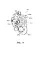
- Figures 7 - 12 describe the gear train of the process cartridge.
- the photoconductive drum 7 in this embodiment comprises the drum cylinder 7A and the photoconductive layer coated on the entirety of the peripheral surface of the drum cylinder 7A.
- a drum gear 7a is solidly attached to one end of the drum cylinder 7A.
- the drum gear 7a transmits the rotational driving force to the charge roller 8, and also to the transfer roller 4 and development roller 10d.
- the drum gear 7a is solidly attached to one end of the drum cylinder 7A, as described above, and its axial line coincides with that of the drum cylinder 7A.
- the drum gear 7a comprises the helical gear portions 7a2 and 7a3, and a shaft portion 7a4.
- the helical gear portions 7a2 and 7a3 are the gear proper portions of the drum gear 7a, and are on the outward side of the drum cylinder 7A in terms of the axial direction of the drum cylinder 7A.
- the shaft portion 7a4 constitutes the center portion of the drum gear 7a, and which overlaps the helical gear portions 7a2 and 7a3, in terms of the radius direction of the drum gear 7a.
- the helical gear portions 7a2 and 7a3 are cylindrical, and the shaft portion 7a4 is extended in the holes of the cylindrical helical gear portions 7a2 and 7a3, with its axial line coinciding with those of the cylindrical helical gear portions 7a2 and 7a3.
- This cylindrical space 7a5 constitutes the space into which the bearing portion 107b of the side holder 107 fits as the photoconductive drum 7 is attached to the cartridge frame (drum holding frame 102), so that the shaft portion 7a4 is rotatably supported by the bearing portion 107b.
- the drum gear 7a also comprises the triangular coupling portion 7a1, that is, a projection constituting the coupling means on the cartridge side, which projects from the outward end of the shaft portion 7a4.
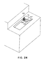
- this projection 7a1 engages with the coupling means of the apparatus main assembly, that is, a driving force transmitting member 200 ( Figure 24).
- the driving force transmitting member 200 has a roughly triangular recess, and the projection 7a1 fits into this recess to receive the rotational driving force from the apparatus main assembly A0.
- the projection 7a1 is twisted around its rotational axis, and its cross section perpendicular to its rotational axis is polygonal.
- the recess of the driving force transmitting member 200 is twisted around the rotational axis of the driving force transmitting member 200, and its cross section perpendicular to the rotational axis of the driving force transmitting member 200 is polygonal.
- the drum gear 7a in this embodiment is structured so that the end surface of the shaft portion 7a4 is on the inward side by an amount of E relative to the Outward end surface of the helical gear 7a, more specifically, the end surface of the helical gear portion 7a2.
- the projection 7a1 partially overlaps the helical gear portion 7a2 in terms of the radius direction of the helical gear 7a.
- the drum gear 7a in this embodiment is wider in terms of its axial direction, being therefore superior, in terms of physical strength as well as meshing ratio, than a drum gear in accordance with the prior arts. Thus, it is possible to an excellent image.
- the shaft portion 7a4 is rotationally supported by the bearing portion 107b of the side holder 107, which is in the cylindrical space 7a5 between the peripheral surface of the shaft portion 7a4 and the inward surface of the cylindrical gear proper portions of the drum gear 7a. Therefore, the repulsive force resulting from the meshing of the gears are caught directly below the teeth of the gears, assuring that the repulsive force does not work in the direction to bend the photoconductive drum 7. Therefore, it is assured that the photoconductive drum 7 is rotationally driven in the preferable manner.
- the drum gear 7a in this embodiment has the first helical gear portion 7a2, which is on the outward side in terms of the lengthwise direction of the cylinder 7A, and the second helical gear portion 7a3, which is on the inward side.
- the first and second helical gear portions 7a2 and 7a3 are disposed next to each other, with their rotational axes coinciding.
- the first helical gear portion 7a2 is smaller than the second helical gear portion 7a3.
- first and second helical gear portions 7a2 and 7a3 are made different in the direction of twist. More specifically, as seen from the drum side, the first helical gear portion 7a2 is twisted rightward, whereas the second helical gear portion 7a3 is twisted leftward.
- the first helical gear portion 7a2 pushes the gear, which is being driven by the helical gear portion 7a2, in the direction opposite to the location of the drum cylinder 7A, that is, inward of the process cartridge B
- the second helical gear portion 7a3 pushes the gear, which is being driven by the helical gear portion 7a3, in the direction opposite to the location of the helical gear 7a, that is, outward direction of the process cartridge B.
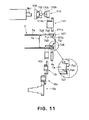
- the gear portion 110b of a geared coupler 110 which transmits the rotational driving force to the charge roller 8, is pushed in the direction opposite to the location of the gear portion 110b in terms of the lengthwise direction of the charge roller 8, that is, inward of the process cartridge B indicated by an arrow mark in Figure 11.
- An idler gear 111 is a step gear having two gear portions 111a and 111b different in diameter, and is rotationally supported by the shaft 102c ( Figure 5) which is a part of the drum supporting frame 102.
- the end portion of the shaft 102c is supported by the side holder 107, being prevented from being broken off by the force resulting from the driving of the idler gear 111 by the gear in mesh with the idler gear 111.
- the two gear portions 111a and 111b of the idler gear 111 are in mesh with the gear portion 110b of the geared coupler 110, and the first helical gear portion 7a2 of the drum gear 7a, respectively, and transmit the rotational driving force from the drum gear 7a to the gear portion 110b of the geared coupler 110.
- the geared coupler 110 has the aforementioned gear portion 110b, and the coupler proper portion 110a integral with the gear portion 110b.
- the coupler proper portion 110a of the geared coupler 110 is shaped like a pair of parallel cylinders connected by a roughly rectangular plate placed between their peripheral surfaces.
- the pair of the cylindrical portions of the coupler proper portion 110a are symmetrical with respect to the rotational axis of the coupler proper portion 110a.
- the gear portion 110b of the geared coupler 110 meshes with the aforementioned idler gear 111 and transmits the rotational driving force.
- the geared coupler 110 As the rotational driving force is transmitted to the charge roller 8 through the geared coupler 110, the geared coupler 110 is subjected to the force generated in the direction perpendicular to the rotational axis of the geared coupler 110 by the idler gear 111 in mesh with the gear portion 110b of the geared coupler 110.
- the geared coupler 110 is supported at both ends in terms of its axial direction. Therefore, the geared coupler 110 is provided with a shaft portion 110c having a predetermined diameter.
- the shaft portion 110c is between the coupler proper portion 110a and gear portion 110b, and its rotational axis coincides with that of the geared coupler 110.
- the geared coupler 110 is also provided with a hole 110d with a predetermined diameter, which is located on the side opposite to the shaft portion 110c in terms of the axial direction of the geared coupler 110.
- the geared coupler 110 is rotationally supported by the shaft portion 106a of a supporting member 106, which is attached to the drum supporting frame 102, along with the side holder 107.
- the geared coupler 110 couples with the first coupling portion 112a of an intermediary coupler 112, and transmits the rotational driving force.
- Figure 8 is a sectional view of the coupled combination of the geared coupler 110, intermediary coupler 112, and coupler 109, describing how they are coupled.
- the drawing shows only the coupler proper portion 110a of the geared coupler 110, and only the coupler proper portion 109c of the coupler 109.
- the coupler proper portion 110a is hatched in order to differentiate the coupler proper portion 110a from the coupler proper portion 109c.
- the intermediary coupler 112 is sandwiched between the coupler 109 and geared coupler 110.
- the intermediary coupler has a second coupling portion 112b, which is on coupler 109 side of the intermediary coupler 112, and a pair of first coupling portions 112a, which is on the geared coupler 110 side.
- the second coupling portion 112b is a hole elongated in the direction perpendicular to axial direction of the intermediary coupler 112, and into which the coupler proper portion 109c fits.
- Each of the pair of first coupling portions 112a is a hole open at the peripheral surface of the coupler 112 as well as one of the lateral surfaces of the coupler 112.
- the pair of first coupling portions 112a are where the pair of couplers proper portions 110a of the geared coupler 110 fit one for one.
- the first coupling portions 112b in the form of an elongated hole is symmetrical with respect to the rotational axis of the intermediary coupler 112, and the pair of the first coupling portions 112a in the form of a groove are symmetrically positioned relative to each other with respect to the axial line of the intermediary coupler 112.
- the first and second coupling portions 112a and 112b are positioned so that the center line of the first coupling portion 112a parallel to the lengthwise direction of the first coupling portion 112a, and the center line of each of the pair of second coupling portions 112b parallel to the lengthwise direction of the second coupling portion 112b, do not become parallel to each other, that is, the angle between them does not become zero; preferably, they are positioned so that the two lines become perpendicular to each other, as shown in Figure 8.
- the charge roller 8 is provided with the coupler 109 as a driving force catching member, which is attached to one end of the shaft portion 8b1 of the charge roller 8. More specifically, one end of the shaft portion 8b1 of the charge roller 8 is given a D-shaped cross section, and is put through the D-shaped centet hole of the coupler 109.
- the coupler 109 has a pair of the couplers proper portions 109c in the form of a cylindrical projection, which are symmetrically positioned relative to each other with respective to the axial line of the coupler 109. These couplers proper portions 109c fit into the pair of second coupling portions 112b of the intermediary coupler 112, one for one, and catch the rotational driving force.
- the first coupling portion 112a of the intermediary coupler 112 is in the form of an elongated hole. Therefore, while the intermediary coupler 112 and geared coupler 110 are in the properly coupled state, that is, while the projection 110a is properly situated in the hole 112a, there is a certain amount of play between the end surface of the coupling portion 112a and the peripheral surface of the corresponding projection 110a, in terms of the lengthwise direction of the coupling portion 112a, allowing the projection 110a to slide in the lengthwise direction of the coupling portion 112a.
- the pair of second coupling portions 112b are in the form of a groove with an open end extending in the radius direction of the coupler 112. Therefore, while the intermediary coupler 112 and coupler 109 are in the properly coupled state, in other words, while each projection 109c is properly situated in the corresponding hole 112b, there is a certain amount of play between the internal surface of the hole 112b and the peripheral surface of the corresponding projection 109c, allowing the projection 109c to slide in the lengthwise direction of the hole 112b.
- the charge roller 8 is rotated in such a direction that in the contact area between the charge roller 8 and photoconductive drum 7, the peripheral surface of the charge roller 8 moves in the direction opposite to the direction in which the peripheral surface of the photoconductive drum 7 moves. Therefore they rub against each other, increasing the frequency at which a given point of the peripheral surface of the charge roller 8 (photoconductive drum 7) comes into contact with the peripheral surface of the photoconductive drum 7 (charge roller 8).
- the drum gear 7a drives the charge roller 8 with the interposition of the idler gear 111 and geared coupler 110. It also drives the development roller 10, transfer roller 4, and toner conveying member (conveyance roller) 10b, as shown in Figure 10.
- the first helical gear portion 7a2 is indirectly in mesh, with the interposition of the idler gear 111, with the gear portion 110b of the geared coupler 110 attached to one end of the shaft of the charge roller 8, and transmits the rotational driving force to the charge roller 8. Further, the first helical gear portion 7a2 is meshes with a gear 4a attached to one end of the shaft of the transfer roller 4, and transmits the rotational driving force to the transfer roller 4 at the same time as it transmits the rotational driving force to the charge roller 8.
- the second helical gear portion 7a3 of the drum gear 7a is in mesh with the gear 10n attached to one end of the shaft of the development roller 10d, and rotationally drives the development roller 10d.
- the gear 10n of the development roller 10d is indirectly in mesh, with the interposition of an idler gear 10t, that is, a step gear, and an idler gear 10u, that is, a step gear, with a gear 10v attached to one end of the conveyance roller 10b, and transmits the rotational driving force to the conveyance roller 10b.
- the drum gear 7a has the first and second helical gear portions 7a2 and 7a3, which are different in the direction in which their teeth are twisted, as described above.
- the development roller 10d has the development roller gear 10n attached to one end of the development roller 10d. This development roller gear 10n is in mesh with the second helical gear portion 7a3 of the drum gear 7a, and is rotationally driven by the drum gear 7a, as described above.
- the transfer roller 4 has the transfer roller gear 4a attached to one end of the transfer roller 4.
- This transfer roller gear 7a is in mesh with the first helical gear portion 7a2 of the drum gear 7a, and is rotationally driven by the drum gear 7a.
- the first helical gear portion 7a2 of the drum gear 7a in this embodiment is twisted in the direction to push the development roller 10d in the outward direction indicated by an arrow mark in Figure 11, whereas the second helical gear portion 7a3 of the drum gear 7a is twisted in the direction to push the charge roller 8 and transfer roller 4 in the inward direction indicated by the arrow mark in Figure 11 as described above.
- the second helical gear portion 7a3 of the drum gear 7a is smaller in width in terms of its axial direction than the first helical gear portion 7a2 of the drum gear 7a.
- the second helical gear portion 7a3 of the drum gear 7a is made larger in pitch circle diameter than the first drum gear 7a2 of the drum gear 7a.
- the diameter of the photoconductive drum 7 is 24 mm, and the diameter of the charge roller 8 is 18 mm. Further, the diameter of the development roller 10d is 12 mm.
- the peripheral velocity of the development roller 10d is roughly 118% of that of the photoconductive drum 7, and the peripheral velocity of the charge roller 8 is roughly 80% of that of the photoconductive drum 7.
- the charge roller 8 is rotated in such a direction that in the contact area between the photoconductive drum 7 and charge roller 8, the peripheral surface of the charge roller 8 moves in the direction opposite to the direction in which the peripheral surface of the photoconductive drum 7 moves, and the development roller 10d is rotated in such a direction that in the area in which the peripheral surfaces of the photoconductive drum 7 and development roller 10d are closest to each other, the peripheral surfaces of the photoconductive drum 7 and development roller 10d move in the same direction.
- the photoconductive drum 7 and charge roller 8 rotate in the clockwise direction
- the development roller 10d rotates in the counterclockwise direction, as shown in Figure 1.
- the conveyance roller 10b is rotated in the clockwise direction.
- the helical drum gear 7a of the gear train shown in Figures 10 - 12 has the first helical gear portion 7a2, which is on the outward side in terms of the lengthwise direction of the cylinder 7A, and the second helical gear portion 7a3, which is on the inward side.
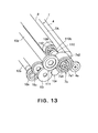
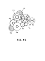
- the helical gear 7a of the gear train shown in Figures 13 - 15 has only one gear portion (similar to helical gear portion 7a2), which plays both the role played by the first helical gear portion 7a2 of the drum gear 7a of the gear train shown in Figures 10 - 12, and the role played by the second helical gear portion 7a3 of the drum gear 7a shown in Figures 10 - 12.
- the drum gear 7a is in mesh with the idler gear 111, gear 4a, and gear 10n; the outward side of the drum gear 7a, in terms of its axial direction, is in mesh with the idler gear 111 and gear 4a, and the inward side of the drum gear 7a is in mesh with the gear 10n.
- the side holder 107 has: a hole 107a for the reinforcement of the shaft 102 for supporting the idler gear 111; a bearing portion 107b for rotationally bearing the photoconductive drum 7; and a coupler of joggles 107h and 107i for precisely positioning the side holder 107 relative to the drum holding frame 102.
- the side holder 107 has a through hole 107c ( Figure 5), through which an assembly tool for aligning the teeth of the drum gear 7a and the teeth of the idler gear 111 is inserted into the internal space of the side holder 107, in order to mesh the drum gear 7a and idler gear 111 during the process cartridge assembly.
- the cleaning members 114 will be described later in detail.
- the shaft portions 8b1 and 8b2 of the charge roller 8 are rotationally borne by the bearing 103a and 103b engaged with the lengthwise end portions of the drum supporting frame 102. More specifically, the shaft portion 8b2, that is, the shaft portion on the electrical contact member 113 side, is fitted with the bearing 103a formed of electrically conductive plastic, and the bearing 103a is attached to a predetermined portion of the drum supporting frame 102, with the interposition of a spring 104 for keeping the charge roller 8 pressed upon the photoconductive drum 7.
- the shaft portion 8b1 that is, the shaft portion on the side with no electrical contact member, is fitted with the bearing 103b formed of plastic, and the bearing 103b is attached to another predetermined portion of the drum supporting frame 102, with the interposition of the spring 104 for keeping the charge roller 8 pressed upon the photoconductive drum 7.
- one end of the shaft 8b1 of the charge roller 8 is fitted with the aforementioned coupler 109 and intermediary coupler 112 in this order. Then, the end of the charge roller 8 with the electrical contact member 113 is fitted with the bearing 103a, and the end of the charge roller 8 with no electrical contact member is fitted with the bearing 103b.
- the charge roller 8 is coated in advance with the aforementioned electrically conductive microscopic particles.
- the geared coupler 110 is fitted into the hole 108 of the drum supporting frame 102, with the coupling portion of the geared coupler 110 aligned with the elongated hole of the intermediary coupler 112.
- the idler gear 111 is fitted around the supporting shaft 102c of the drum supporting frame 102, while being meshed with the gear portion 110b of the geared coupler 110.
- the supporting member 106 is attached to the drum supporting frame 102, while inserting the shaft portion 106a of the supporting member 106 into the hole 110d of the geared coupler 110, being therefore precisely positioned relative to the drum supporting frame 102.
- the photoconductive drum 7 is precisely positioned relative to the drum supporting frame 102 with the use of a tool. Then, from the side opposite to the side with the drum gear, the drum supporting shaft 100 is put through the hole 102a of the drum supporting frame 102, and the flange of the photoconductive drum 7, solidly fixing the drum suppbrting shaft 100 to the drum supporting frame 102, and rotationally supporting the photoconductive drum 7.
- the side holder 107 is attached to the drum supporting frame 102, precisely positioning the side holder 107 relative to the drum supporting frame 102, while fitting the projection 7a1 of the drum gear 7a into the hole 107b of the side holder, and the bearing portion 107b into the cylindrical space 7a5 of the drum gear 7a.
- a tool for rotating the idler gear 111 is inserted through the through hole 107c of the side holder 107, and the side holder 107 is solidly fixed to the drum supporting frame 102 with the use of small screws, while rotating the idler gear 111 by the inserted tool so that the first helical gear portion 7a2 smoothly meshes with the idler gear 111.
- the developing means 10 comprises the toner storage-developing means frame 10f1 and frame lid 10f2, which are joined to create the toner chamber (toner storage portion) 10a and development chamber 10i.
- the toner storage-developing means frame 10f1 is provided with the opening 10k which the toner in the toner chamber 10a passes when it is supplied to the development roller 10d.
- the toner passage opening 10k of toner storage-developing means frame 10f1 of the process cartridge B is blocked with a multilayer toner sealing member 27 having a cover film portion 27b thermally welded to the seal attachment portion of the toner storage-developing means frame 10f1, with the use of laser light.
- the cover film portion 27b is provided with a thermally weldable layer 31 for fixing the toner sealing member 27.
- the details of the structure of the toner sealing member 27 are well known to the people in this business, and are disclosed in, for example, Japanese Laid-open Patent Application 11-102105, etc. Thus, for the details, this patent application or the like should be referred to.
- the toner sealing member 27 is pasted to the seal attachment portion 10h, which extends along the four edges of the aforementioned toner passage opening 10k.
- the toner sealing member 27 is precut by a laser to a depth of half its thickness, as described above (Japanese Laid-open Patent Application 11-102105).
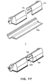
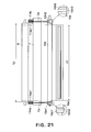
- One lengthwise end of the toner storage-developing means frame 10f1 is provided with a toner inlet (unshown), that is, an opening, through which the toner chamber 10a is filled with toner, and which is sealed with a cap 10j ( Figure 19) after the filling of the toner chamber 10a with toner.
- a toner inlet that is, an opening, through which the toner chamber 10a is filled with toner, and which is sealed with a cap 10j ( Figure 19) after the filling of the toner chamber 10a with toner.
- an end seal 10r for preventing the toner from leaking from the lengthwise ends of the development roller 10d, a sealing member 10s for preventing toner from leaking from the lengthwise ends of the development blade 10e, and a sheet-like member 10t for preventing toner from scattering from the gap under the development roller 10d, are pasted to the toner storage-developing means frame 10f1 and frame lid 10f2, with the use of double-sided adhesive tape, or the like.
- the development blade 10e is solidly fixed to the toner storage-developing means frame 10f1, by the lengthwise ends of the metallic plate portion 10e1 of the development blade 10e, with the use of small screws.
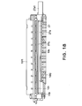
- One (on the left side in Figure 19) of the two end members (holding members) 10g covers the gear train comprising: the development roller gear 10n ( Figures 10 and 11) solidly fixed to one end of the development roller 10d and in mesh with the first helical gear portion 7a2 of the drum gear 7a ( Figure 5) solidly fixed to one end of the photoconductive drum 7; and the two idler gears 10u and 10t for transmitting the driving force from the development roller gear 10n to the conveyance gear (unshown) of the toner conveyance member 10b.
- the other end member 10g (on the right side in Figure 19) is provided with a hard tab 10g1, which will be described later.
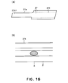
- the extended tab portion 27a (Figure 16) of the toner sealing member 27 is folded back at one end 10p ( Figure 18) of the toner passage opening 10k, all the way to the other end of the toner passage opening 10k, and is extended outward through the hole 10f11 ( Figure 19) of the toner storage-developing means frame 10f1.
- the tab proper portion 27a1 of the extended tab portion 27a of the toner sealing member 27 is further extended outward through the hole 10g6 of the end member 10g, and the through hole 10g4 of the hard tab 10g1, so that the surface R (surface coated with sealant layer 31) of the extended tab portion 27a, shown in Figure 16, thermally fixable to the hard tab 10g1 faces the handle 10g1.
- the end of the tab proper portion 27a1 is thermally fixed to a predetermined area of the hard tab 10g1 ( Figure 19).
- the hard tab 10g1 is an integral part of the end member 10g, and is formed so that it can be easily torn off from the end member 10g. More specifically, the portion by which the hard tab 10g1 is connected to the main structure of the end member 10g is made very thin so that the hard tab 10g1 can be easily separated from the main structure by bending.
- the hard tab 10g1 is integrally formed with the end member 10g.
- it is formed of high impact polystyrene (HIPS), acrylonitrile-butadiene polymer (ABS), etc., that is, copolymers containing styrene.
- HIPS high impact polystyrene
- ABS acrylonitrile-butadiene polymer
- the end portion 27a1, or tab proper, of the extended tab portion 27a is thermally welded to the hard tab 10g1.
- the end member 10g is provided with an arm-like portion 10g7, which protrudes toward the drum supporting frame 102.
- the arm-like portion 10g7 has a hole 10g8, which is in the end portion of the arm-like portion 10g7, extending in the lengthwise direction of the process cartridge B.
- the drum supporting frame 102 and the end member 10g can be joined by putting a pin (unshown) through the hole 10g8 of the arm-like portion of the end member 10g, and the unshown hole of the drum supporting frame 102, so that they can be rotated about the pin.
- the arm-like portion 10g7 is also provided with a spring holding portion 10g9, which protrudes from the top surface of the arm-like portion 10g7, and a compression coil spring is placed in the compressed state between the arm-like portion 10g7 and drum supporting frame 102, with one end of the compression coil spring fitted around the spring holding portion 10g9.
- the end portion of the development roller 10d are fitted with a gap maintaining members (spacer) 10m (10m1 and 10m2), one for one, and the spacers 10m are pressed on the peripheral surface of the photoconductive drum 7. Therefore, a predetermined distance is kept between the peripheral surfaces of the development roller 10d and photoconductive drum 7.
- the spacer 10m is in the form of a cap, and each end of the development roller 10d is fitted with the cap-like spacer 10m.
- the center portion of the peripheral surface of the cap-like spacer 10m in terms of its axial direction, having a predetermined width, is raised in relation to adjacent portions of the peripheral surfaces, and, this portion is pressed on the peripheral surface of the photoconductive drum 7.
- the development unit D and drum frame unit C are joined, as described above, to complete the process cartridge B.
- toner particles sometimes floats in the image forming apparatus main assembly, although by only a very small amount.
- one-piece cleaning members 114 (114a and 114b) are attached to the end portions of the drum supporting frame 102, one for one, with the use of double-sided adhesive tape, in such a manner that the cleaning members 114 contact the peripheral surfaces of the right and left lengthwise ends of the photoconductive drum 7, one for one.
- These cleaning members 114 are capable of reliably taking into the nonwoven fabric portion or the like, the stray toner particles having adhered to the peripheral surface of the photoconductive drum 7, without causing the stray toner particles to fall within the apparatus main assembly; in other words, they can remove the stray toner particles on the photoconductive drum 7 in a preferable manner, reducing frictional resistance as much as possible, preventing thereby the increase in the driving force (rotational driving force) necessary to rotate the photoconductive drum 7.
- the adhesion of the stray toner particles such as the above described floating toner particles to the portions of the photoconductive drum 7, outside the changing range of the charge roller 8, that is, the portions of the photoconductive drum 7 extending outward beyond the ends of the charge roller 8, may result in the contamination of the image edges and/or recording medium edges by the stray toner particles.
- each end of the development roller 10d is capped with the cap-like roller 10m (10m1 and 10m2) as a spacer, the raised center portion 10m3 of which is kept pressed on the peripheral surface of the photoconductive drum 7.
- the cleaning members 114 (114a and 114b) are disposed in alignment with the cap-like rollers 10m (10m1 and 10m2), respectively, in terms of the direction perpendicular to the axial direction of the photoconductive drum 7 (charge roller 8, development roller 10d), with the presence of a gap between the cleaning member 114 and corresponding cap-like member 10m.
- the range Ca across which the raised center portion of the cap-like roller 10ml as a spacer, of the development roller 10d, is in contact with the left end portion of the peripheral surface of the photoconductive drum 7, falls within the range of the first cleaning member 114a disposed in contact with the left end portion of the peripheral surface of the photoconductive drum 7.
- the inward edge 114a1 of the first cleaning member 114a is outside the range Ld, in terms of the lengthwise direction of the photoconductive drum 7, across which the development process is carried out by the development roller 10d, and inside the range Lc, across which the charge roller 8 is in contact with the photoconductive drum 7.
- the range Cb across which the raised center portion of the cap-like roller 10m2, as a spacer, of the development roller 10d, is in contact with the right end portion of the peripheral surface of the photoconductive drum 7, falls within the range of the second cleaning member 114b disposed in contact with the right end portion of the peripheral surface of the photoconductive drum 7.
- the inward edge 114b1 of the first cleaning member 114b is outside the range Ld, in terms of the lengthwise direction of the photoconductive drum 7, across which the development process is carried out by the development roller 10d, and inside the range Lc, across which the charge roller 8 is in contact with the photoconductive drum 7.
- the toner particles adhering to the photoconductive drum 7 can be removed by taking them into the first and second cleaning members 114a and 114b.
- the stray toner particles do not agglomerate on the peripheral surface of the photoconductive drum 7, across the areas corresponding to the ranges across which the cap-like rollers 10m (10m1 and 10m2) remain in contact with the photoconductive drum 7. Therefore, the distance between the photoconductive drum 7 and development roller 10d is kept constant, making it possible to form an excellent image.
- a laminar material for example, a laminar combination of a layer of elastic substance and a layer of nonwoven fabric
- the material for the cleaning members 114 make it possible to prevent the stray toner particles from adhering to the photoconductive drum 7, across the areas corresponding to the ranges across which the cap-like rollers 10m (10m1 and 10m2) remain in contact with the photoconductive drum 7, without increasing component count, but also to produce a sturdy and resilient cleaning member, and to improve assembly quality and efficiency.
- the above described structural arrangement makes it possible for the first and second cleaning members 114a and 114b to remove the toner particles adhering the peripheral surface of the photoconductive drum 7, across the range in which the photoconductive drum 7 is not charged, that is, outside the range across which the charge roller 8 is in contact with the photoconductive drum 7. Therefore, toner particles are prevented from adhering to the image edges and/or recording medium edges. Therefore, it is possible to form an excellent image.
- the pair of cleaning members 114 (114a and 114b) are disposed in contact with the lengthwise ends of the photoconductive drum 7, one for one. However, it may be only one of lengthwise ends of the photoconductive drum 7 that is provided with the cleaning member 114.
- the process cartridge B assembled as described above is mounted into the image forming apparatus main assembly A0.
- the process cartridge B is mounted into the image forming apparatus main assembly A0.
- the side holder 107 attached to the cartridge frame (drum supporting frame 102) of the process cartridge B is provided with an arcuate portion (first engagement portion) 107d, as a guide, by which the process cartridge B is guided when it is mounted into the image forming apparatus main assembly A0; and an arcuate portion (second engagement portion) 107e, as a rotational control portion, which controls the attitude of the process cartridge B when the process cartridge B is mounted into the image forming apparatus main assembly A0.
- the arcuate portion 107d is at the bottom of the cartridge frame, and the center of its curvature coincides with the axial line of the photoconductive drum 7, whereas the arcuate portion 107e is located at the corner of the side holder 107.
- the arcuate portion 107d is on the outward side of the drum unit D, but, as seen from the drum shaft direction, it partially overlaps with the drum unit D.
- the rotation control portion 107e is on the outward side of the drum unit D, and, as seen from the axial direction of the photoconductive drum 7 of the development unit D, it falls within the projection of the development unit D.
- the rotation control portion 107e is on the trailing side of the arcuate portion 107d.
- the triangular coupling portion 7a1 which catches the driving force from the image forming apparatus main assembly A0 is on the inward side of the side holder 107, in terms of the drum shaft direction.
- the process cartridge B does not need to be provided with dedicated positioning portions such as the cover portion 50 of the triangular coupling portion 7a1 and projection 51 of the process cartridge in accordance with the prior arts, shown in Figure 30, which function as a positioning portion (positioning boss CB) and a guide, respectively. Therefore, it is possible to make the cartridge size smaller compared to a cartridge in accordance with the prior arts.
- the image forming apparatus main assembly A0 is provided with a guiding portion Ga as a first guide which guides the process cartridge B into the image formation position (properly mounted position), by the aforementioned arcuate portion 107d and rotation control portion 107e of the process cartridge B; the arcuate portion 107d and rotation control portion 107e are rested on the guiding portion Ga and are allowed to slide thereon.
- the process cartridge B is provided with a projection 102a for covering the drum supporting shaft 100, and a projection 102b for controlling the process cartridge position during the mount or removal of the process cartridge B.
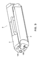
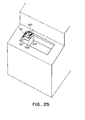
- the projection 102a and 102b protrude from the end surface of the drum supporting frame 102 on the side opposite to the end surface with the side holder 107, in terms of the drum shaft direction, as will be easily understood with reference to Figure 3 in addition to Figures 22 and 24.
- the image forming apparatus main assembly A0 is provided with a guiding portion Gb as a second cartridge guide on the main assembly side, which coordinates with the side holder 107 in order to maintain the attitude of the process cartridge B set by the side holder 107 so that the process cartridge B does not become tilted relative to the drum shaft direction.
- the a lid 6a which also serves as d delivery tray 6 of the image forming apparatus main assembly A0 is opened to expose the guiding portions Ga and Gb of the apparatus main assembly A0.
- the process cartridge B is to be held so that its arcuate portion 107d and rotation control portion 107e are on the front and rear sides, respectively, as indicated by the single-dot line in Figures 22 and 23.
- the arcuate portion 107d and rotation control portion 107e are to be rested on the first guiding surface Ga1, the front portion of which is somewhat undulatory, while holding the process cartridge B in the above described manner.
- the projections 102a and 102b of the process cartridge B are rested on the first guiding surface Gb1 of the guiding portion Gb.
- the arcuate portion 107d and rotation control portion 107e of the process cartridge B are guided to their designated image formation positions, while sliding on, being thereby guided by, the second guiding surface Ga2 of the guiding portion Ga, which is roughly perpendicular to the first guiding surface Ga1, the third guiding surface Ga3 of the guiding portion Ga, which roughly horizontally extends from the bottom of the second guiding surface Ga2, and the fourth guiding surface Ga4 of the guiding portion Ga, which extends from the inward end of the third guiding surface Ga3 in an arcuately dipping manner.
- the process cartridge B rests on the third guiding surface Ga3, with its arcuate portion 107d being in contact with the fourth guiding surface Ga4, as a first portion of catching and supporting the process cartridge B, and the curved surface of the rear portion of the rotation control portion 107e being in contact with the second guiding surface Ga2, as shown in Figure 26.
- the transfer roller 4 and photoconductive drum 7 have come into contact with each other, and therefore, the process cartridge B has come under the pressure working in the direction indicated by an arrow mark in Figure 26.
- the third contact portion 107g is placed in contact with the second guiding surface Ga2 adjacent to the third guiding surface Ga3, preventing the positional deviation of the process cartridge B.
- the third contact portion 107g may be either integral with the second contact portion (rotation control portion) 107e, or discrete.
- the projections 102a and 102b which are on the other side of the process cartridge B, are guided to their designated image formation positions while sliding on, being thereby guided by, the second guiding surface Gb2 of the guiding portion Gb, which is roughly perpendicular to the first guiding surface Gb1, the third guiding surface Gb3 of the guiding portion Gb, which roughly horizontally extends from the bottom of the second guiding surface Gb2, and the fourth guiding surface Gb4 of the guiding portion Gb, which extends from the inward end of the third guiding surface Gb3 in an arcuately dipping manner.
- the process cartridge B rests on the third guiding surface Gb3, with its projections 102a and 102b being between the fourth guiding surface Gb4, as a second portion for catching and supporting the process cartridge B, and the second guiding surface Gb2, as shown in Figure 28.
- the process cartridge B is mounted into the proper position in the apparatus main assembly.
- the lid 6a of the image forming apparatus main assembly A0 is to be closed.
- the triangular coupling portion 7a1 of the cartridge B couples with the driving force transmitting member 200, shown in Figure 24, having the roughly triangular twisted hole, allowing the rotational driving force to be transmitted from the image forming apparatus main assembly A0 to the process cartridge B.
- the process cartridge B is rotated about the rotational axis of the triangular coupling portion 7a1 having coupled as shown in Figure 27, which coincides with the rotational axis of the photoconductive drum 7. Consequently, gaps x and y are created between the arcuate portion 107d and contact portion 107g of the process cartridge B, and the fourth guiding surface Ga4 and second guiding surface Ga2 of the guiding portion Ga, respectively, and the rotation control portion 107e of the side holder 107 comes into contact with the third guiding surface Ga3, as a regulating surface, of the guiding portion Ga, fixing thereby the attitude of the process cartridge B in terms of the rotation of the process cartridge B about the rotational axis of the photoconductive drum 7.
- the projection 102a of the drum supporting frame 102 settles into the U-shaped groove, as a cartridge positioning portion, that is, the fourth guiding surface Gb4, and is kept there by the force generated by the resiliency of the transfer roller 4 and the force from a spring (unshown) for preventing the formation of a blurred image traceable to the driving of the process cartridge B.
- the projection 102b of the drum supporting frame 102, it is designed in position and size so that after the proper mounting of the process cartridge B into the image forming apparatus main assembly A0, it remains in noncontact with the image forming apparatus main assembly A0, as long as the component dimension errors and assembly errors of the image forming apparatus main assembly A0 are within the normal tolerance.
- the above described attitude of the process cartridge B is the attitude in which the process cartridge B is kept during an image forming operation.
- an image forming operation can be started as soon as the process cartridge B assumes this attitude in the image forming apparatus main assembly A0.
- the projection 102b comes into contact with the fifth guiding surface Gb5, which is the top surface of the guiding portion Gb, preventing thereby the front side of the process cartridge B, in terms of the cartridge extraction direction, from rotating upward more than a predetermined angle.
- first and second contact portions of the process cartridge B 200 are as described above.
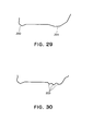
- the first and second contact portions may be polygonal (200 and 201, respectively) as shown in figure 29.
- the second contact portion may have ridges 202 as shown in Figure 30, as long as the counters of these contact portions perform the above described cartridge positioning functions.
- the first, second, and third contact portion of the process cartridge B are arcuate, because when they are arcuate, a part of the second contact portion is allowed to come into contact with the fourth guiding surface Ga4, even if the process cartridge B deviates in attitude due to the tolerance in component dimension.
- the above described embodiment of the present invention is compatible with various well-known developing methods, for example, the two-component magnetic brush developing method, cascade developing method, touch-down developing method, cloud developing, etc.
- the photoconductive drum in this embodiment comprises a cylinder formed of aluminum alloy or the like, and a layer of photoconductive substance placed on the entirety of the peripheral surface of the cylinder by deposition, painting, or the like.
- plastics As for the material for the drum supporting frame, toner storage-developing means frame, frame lid, etc., of a process cartridge in accordance with the present invention, there are such plastics as polystyrene, ABS (acrylonitrile-butadiene-styrene copolymer), denatured PPE resin (polyphenylene-ether), denatured PPO resin (polyphenylene oxide), polycarbonate, polyethylene, polypropylene, etc.
- ABS acrylonitrile-butadiene-styrene copolymer
- denatured PPE resin polyphenylene-ether
- denatured PPO resin polyphenylene oxide
- polycarbonate polyethylene, polypropylene, etc.
- the above described process cartridge is, for example, a cartridge comprising an electrophotographic photoconductive member, a developing means, and at least one more processing means.
- the present invention is compatible with: a cartridge in which an electrophotographic photoconductive member, a developing means, and a charging means are integrally disposed, and which is removably mountable in the main assembly of an image forming apparatus; a cartridge in which an electrophotographic photoconductive member and a developing means are integrally disposed, and which is removably mountable in the main assembly of an image forming apparatus; and the like, in addition to the process cartridge B in the above described embodiment of the present invention.
- the present invention is also compatible with: a cartridge in which an electrophotographic photoconductive member, and a charging means or a developing means, are integrally disposed, and which is removably mountable in an image forming apparatus; a process cartridge in which a charging means, a developing means, and an electrophotographic photoconductive member are integrally disposed, and which is removably mountable in an image forming apparatus; and a cartridge in which a minimum of a developing means and an electrophotographic photoconductive member are integrally disposed, and which is removably mountable in an image forming apparatus.
- the image forming apparatus in the above described embodiment of the present invention is a laser beam printer.
- the application of the present invention is not limited to a laser beam printer.
- the present invention is also applicable to various image forming apparatuses other than a laser beam printer, for example, an electrophotographic copying machine, a facsimileing apparatus, a wordprocessor, etc., which is obvious.
- the present invention makes it possible to more reliably mount a process cartridge into the main assembly of an image forming apparatus, and remove the process cartridge therefrom, compared to the prior arts. Further, the present invention makes it possible to more accurately position a process cartridge relative to the main assembly of an image forming apparatus, compared to the prior arts. Further, the present invention makes it possible to keep a process cartridge more stable in attitude during an image forming operation, compared to the prior arts.
- a process cartridge detachably mountable to a main assembly of an electrophotographic apparatus said cartridge includes a photosensitive drum; process means; a first contact portion provided on a bottom surface of a cartridge frame provided at one longitudinal end, the first portion being guided by a first assembly side guide when the cartridge is mounted, wherein the first portion is disposed at a leading portion with respect to a cartridge mounting direction, and the first portion is mounted to a first assembly side receiving portion when the cartridge is mounted; a cartridge coupling disposed above the first portion, the coupling being engageable with a assembly side coupling to receive a rotational force from the assembly; a second contact portion provided on a bottom surface of a cartridge frame provided at one longitudinal end of the photosensitive drum, the second portion being disposed behind the first portion with respect to the mounting direction, wherein the second portion is effective to limit rotation of the cartridge in a rotational direction of the drum; a positioning portion projected outwardly from a cartridge frame provided at the other longitudinal end of the drum, the positioning portion being guided by a second assembly side guide, and
Landscapes
- Physics & Mathematics (AREA)
- General Physics & Mathematics (AREA)
- Engineering & Computer Science (AREA)
- Computer Vision & Pattern Recognition (AREA)
- Electrophotography Configuration And Component (AREA)
- Discharging, Photosensitive Material Shape In Electrophotography (AREA)
Abstract
A process cartridge detachably mountable to a
main assembly of an electrophotographic apparatus,
said cartridge includes a photosensitive drum; process
means; a first contact portion (107d) provided on a bottom
surface of a cartridge frame (107) provided at one
longitudinal end, the first portion being guided by a
first assembly side guide (Ga,Ga1) when the cartridge is
mounted, wherein the first portion is disposed at a
leading portion with respect to a cartridge mounting
direction, and the first portion is mounted to a first
assembly side receiving portion (Ga4) when the cartridge is
mounted. In addition, there may be a cartridge coupling (7a1) disposed above the first
contact portion (107d), the coupling being engageable with a assembly
side coupling to receive a rotational force from the
assembly; and a second contact portion (107e) provided on a
bottom surface of cartridge frame and being disposed behind the first portion
with respect to the mounting direction, wherein the
second portion is effective to limit rotation of the cartridge
in a rotational direction of the drum. Else, there may be a third
contact portion (107g), provided on said cartridge frame at a position
behind said first contact portion (107d) with respect to the mounting
direction, for limiting movement of said process cartridge by an urging
force applied to said photosensitive drum from transferring means (4)
provided in the main assembly of the image forming apparatus when said
process cartridge is mounted.
Description
- The present invention relates to a process cartridge removably mountable in an electrophotographic image forming apparatus, and an electrophotographic image forming apparatus.
- Here, an electrophotographic image forming apparatus means an apparatus which forms an image on recording medium with the use of an electrophotographic image forming method. Examples of an electrophotographic image forming apparatus include an electrophotographic copying machine, an electrophotographic printer (for example, laser printer, LED printer, etc.), a facsimile machine, a wordprocessor, a combination of two or more of the preceding apparatuses (multifunction printer, etc.), etc.
- A process cartridge means: a cartridge in which a charging means, a developing means or a cleaning means, and an electrophotographic photoconductive member, are integrally disposed, and which is removably mountable in the main assembly of an image forming apparatus; a cartridge in which a minimum of one among a charging means, a developing means, and cleaning means, and an electrophotographic photoconductive member, are integrally disposed, and which is removably mountable in the main assembly of an image forming apparatus; or a cartridge in which a minimum of a developing apparatus and an electrophotographic photoconductive member are integrally disposed, and which is removably mountable in the main assembly of an image forming apparatus.
- A process cartridge system which has an electrophotographic photoconductive member, and a single or plurality of processing means which act on the electrophotographic photoconductive member, are integrally disposed in a cartridge removably mountable in the main assembly of an image forming apparatus has long been employed by an electrophotographic image forming apparatus which uses an electrophotographic image firming process. According to a process cartridge system, an apparatus can be maintained by a user him/herself; it is unnecessary to hire a service person. Thus, the employment of a cartridge system drastically improves the apparatus in operational efficiency. Therefore, a cartridge system has been widely used in the field of an image forming apparatus.
- In order to obtain an image of good quality with the use of an electrophotographic image forming apparatus employing a process cartridge system, it is essential that a process cartridge is properly mounted in the predetermined position within the main assembly of the electrophotographic image forming apparatus, and also that the various electrical contacts, driving force transmitting portions, etc., on the cartridge side are correctly connected to the counterparts on the main assembly side of the image forming apparatus; it is essential the two sides are correctly interfaced.
- Figure 31 shows a process cartridge CR, and Figure 32 shows a cartridge guide GL of the main assembly PR of an image forming apparatus. Figure 33 shows an image forming apparatus employing the process cartridge CR.
- Referring to Figures 31 - 33, in order to guide the process cartridge CR and accurately position the process cartridge CR in the image forming apparatus main assembly PR when mounting the process cartridge CR into the image forming apparatus main assembly PR or removing it therefrom, the process cartridge CR is provided with a positioning boss CB, the axial line of which coincides with the axial line of the photoconductive drum, as an electrophotographic photoconductive member, in the process cartridge CR, whereas the image forming apparatus main assembly is provided with a process cartridge mounting guide GL, which guides the process cartridge CR by the positioning boss CB thereof. As a user inserts the process cartridge CR to a predetermined point in the apparatus main assembly GL, along the cartridge mounting guide GL, the process cartridge CR comes into contact with the stopper portion P of the image forming apparatus main assembly PR, being thereby prevented from further rotating about the axial line of the positioning boss CB. Apparatuses having the above described structure have been put to practical use.
- The present invention is a result of further technical development of the above described prior art.
- The primary object of the present invention is to provide a combination of a process cartridge and an electrophotographic image forming apparatus employing a process cartridge system, in which the cartridge is more reliably mounted into, or dismounted from, the main assembly of the image forming apparatus.
- Another object of the present invention is to provide a combination of a process cartridge and an electrophotographic image forming apparatus employing a process cartridge system, in which the process cartridge is more accurately positioned relative to the main assembly of the image forming apparatus when the process cartridge is mounted into the main assembly,
- Another object of the present invention is to provide a combination of a process cartridge and an electrophotographic image forming apparatus employing a process cartridge system, in which the process cartridge remain more stable when the process cartridge is mounted into the main assembly.
- Another object of the present invention is to provide:
- a process cartridge removably mountable in
the main assembly of an electrophotographic image
forming apparatus, comprising:
- an electrophotographic photoconductive drum;
- a single or plurality of processing means which act on the photoconductive drum;
- a first contact portion, which is a part of one of the end portions, in terms of the lengthwise direction of the photoconductive drum, of the bottom surface of the cartridge supporting frame for supporting the photoconductive drum; is guided by a first cartridge guiding portion of the apparatus main assembly of an image forming apparatus, when the process cartridge is mounted into the proper cartridge position in the apparatus main assembly; is on the front side in terms of the direction in which the process cartridge is inserted into the proper cartridge position in the main assembly; and is caught and supported by a first catching and supporting portion of the apparatus main assembly, when the process cartridge is mounted into the proper cartridge position in the apparatus main assembly;
- a coupler, which is located above the first contact portion; couplers with the coupler of the apparatus main assembly to receive the rotational driving force; and accurately position the photoconductive drum;
- a second contact portion, which is a part of one of the end portion, in terms of the lengthwise direction of the photoconductive drum, of the bottom surface of the cartridge supporting frame for supporting the photoconductive drum; is located on the rear side with respect to the first contact portion, in terms of the cartridge mounting direction; and prevents the process cartridge from rotating in the rotational direction of the photoconductive drum more than a predetermined angle, when the process cartridge receives the rotational driving force from the apparatus main assembly after the proper mounting of the process cartridge into the apparatus main assembly; and
- a positioning portion, which is on the outward side of one of the lengthwise ends, in terms of the lengthwise direction of the photoconductive drum, of the cartridge supporting frame for supporting the photoconductive drum; is guided by a second cartridge guiding portion of the apparatus main assembly, when the process cartridge is mounted into the proper position in the apparatus main assembly; and is accurately positioned by a second catching and supporting portion of the apparatus main assembly, which the process cartridge is mounted into the proper cartridge position in the apparatus main assembly, and,
- an electrophotographic image forming apparatus in which the above described process cartridge is removably mountable.
-
- Another object of the prevent invention is to provide:
- a process cartridge removably mountable in
the main assembly of an electrophotographic image
forming apparatus, comprising:
- an electrophotographic photoconductive drum;
- a single or plurality of processing means which act on the photoconductive drum;
- a first contact portion, which is a part of one of the end portions, in terms of the lengthwise direction of the photoconductive drum, of the bottom surface of the cartridge supporting frame for supporting the photoconductive drum; is guided by a first cartridge guiding portion of the apparatus main assembly of an image forming apparatus, when the process cartridge is mounted into the proper cartridge position in the apparatus main assembly; is on the front side in terms of the direction in which the process cartridge is inserted into the proper cartridge position in the main assembly; and is caught and supported by a first catching and supporting portion of the apparatus main assembly, when the process cartridge is mounted into the proper cartridge position in the apparatus main assembly; and
- a third contact portion which is on the rear side of the first contact portion in terms of the cartridge mounting direction; is a part of the cartridge frame; and comes into contact with the counterpart of the apparatus main assembly to prevent the process cartridge from being moved by the pressure generated by the transferring means of the apparatus main assembly, as the transferring means and photoconductive drum are pressed against each other, after the proper mounting of the process cartridge into the apparatus main assembly, and,
- an electrophotographic image forming apparatus in which the above described process cartridge is removably mountable.
-
- These and other objects, features, and advantages of the present invention will become more apparent upon consideration of the following description of the preferred embodiments of the present invention, taken in conjunction with the accompanying drawings.
-
- Figure 1 is a schematic sectional view of the image forming apparatus in one of the preferred embodiments of the present invention, in which a process cartridge in accordance with the present invention has been properly mounted, describing the general structure thereof.
- Figure 2 is a schematic sectional view of the process cartridge in the preferred embodiment of the present invention, describing the structure thereof.
- Figure 3 is a perspective view of the process cartridge in accordance with the present invention, in Figure 2.
- Figure 4 is another perspective view of the process cartridge in accordance with the present invention, in Figure 2.
- Figure 5 is an exploded perspective view of the drum frame unit of the process cartridge in accordance with the present invention.
- Figure 6 is a perspective view of the drum frame unit of the process cartridge in accordance with the present invention.
- Figure 7 is a perspective view of the side holder of the drum frame unit.
- Figure 8 is a plan view of the charge roller driving means, describing the structure thereof.
- Figure 9 is an exploded perspective view of the charge roller driving means, describing the structure thereof.
- Figure 10 is a perspective view of the process cartridge driving mechanism, in the preferred embodiment of the present invention.
- Figure 11 is a schematic sectional view of the gear train of the process cartridge driving mechanism in Figure 10, describing the structure thereof.
- Figure 12 is a plan view of the gear train of the process cartridge driving mechanism in Figure 10, describing the structure thereof.
- Figure 13 is a perspective view of the process cartridge driving mechanism, in another embodiment of the present invention, describing the structure thereof.
- Figure 14 is a schematic sectional view of the process cartridge driving mechanism in Figure 13, describing the structure thereof.
- Figure 15 is a plan view of the process cartridge driving mechanism in Figure 13, describing the structure thereof.
- Figure 16(a) is a perspective view of the toner sealing member in the preferred embodiment of the present invention, and Figure 16(b) is a sectional view of the same toner sealing member.
- Figure 17 is a perspective view of the toner storage-developing means frame, and frame lid, of the cartridge in the preferred embodiment of the present invention, describing how they are joined.
- Figure 18 is a drawing for describing how the toner sealing member is joined with the toner storage-developing means frame.
- Figure 19 is an exploded perspective view of the development unit of the process cartridge in accordance with the present invention.
- Figure 20 is a perspective view of the development unit in Figure 19.
- Figure 21 is a drawing for describing how the cleaning members of the process cartridge in accordance with the present invention are attached.
- Figure 22 is a schematic sectional view of an image forming apparatus, describing how the process cartridge is mounted into the image forming apparatus.
- Figure 23 is a schematic sectional view of the image forming apparatus, describing how the process cartridge is mounted into the image forming apparatus.
- Figure 24 is a perspective view of one of the cartridge guiding portions of the image forming apparatus in the preferred embodiment of the present invention.
- Figure 25 is a perspective view of the other cartridge guiding portion of the image forming apparatus, in the preferred embodiment of the present invention.
- Figure 26 is a drawing for describing how the process cartridge is accurately positioned relative to the image forming apparatus.
- Figure 27 is a drawing for describing how the process cartridge is accurately positioned relative to the image forming apparatus.
- Figure 28 is a drawing for describing how the process cartridge is accurately positioned relative to the image forming apparatus.
- Figure 29 is a schematic drawing of one of the modifications of the contact portions of the process cartridge in accordance with the present invention.
- Figure 30 is a schematic drawing of another modification of the contact portion of the process cartridge in accordance with the present invention.
- Figure 31 is a perspective view of a process cartridge in accordance with the prior arts.
- Figure 32 is a perspective view of one of the cartridge guiding portions of an image forming apparatus in accordance with the prior arts.
- Figure 33 is a schematic sectional view of an image forming apparatus in accordance with the prior arts, which is properly holding the process cartridge in accordance with the prior arts.
-
- Hereinafter, a combination of a process cartridge and an electrophotographic image forming apparatus, in accordance with the present invention, will be described in more detail with reference to the appended drawings.
- In the following description of the present invention, the lengthwise direction of a process cartridge means the direction intersectional (roughly perpendicular) to the direction in which a process cartridge is mounted into, or removed from, the main assembly of an image forming apparatus. It is parallel to the surface of recording medium, and is intersectional (roughly perpendicular) to the direction in which the recording medium is conveyed. The right or left direction means the right or left direction of the recording medium as the recording medium is seen from the rear side in terms of the recording medium conveyance direction. The top surface of a process cartridge means the surface of the process cartridge which will be on the top side after the proper mounting of the process cartridge in the main assembly of an image forming apparatus, and the bottom surface of the process cartridge means the surface of the process cartridge which will be on the bottom side after the proper mounting of the process cartridge in the apparatus main assembly.
- Figure 1 shows one of the preferred embodiments of an electrophotographic image forming apparatus in accordance with the present invention. In this embodiment, a process cartridge B shown in Figure 2 is removably mountable in this electrophotographic image forming apparatus. Figure 1 is a schematic drawing for describing the structure of this electrophotographic image forming apparatus, which is properly holding the process cartridge B in Figure 2. Figure 2 is a schematic drawing for describing the structure of the process cartridge B.
- As for the order of description, the general structure of the prpcess cartridge B and the general structure of the electrophotographic image forming apparatus employing the process cartridge B will be first described. Then, the structure of the mechanism of the image forming apparatus main assembly for guiding the process cartridge B when the process cartridge B is mounted into, or removed from, the main assembly of the electrophotographic image forming apparatus will be described.
- Referring to Figure 1, the electrophotographic image forming apparatus A (which hereinafter will be referred to simply as "image forming apparatus") in this embodiment is a laser beam printer, and has an electrophotographic
photoconductive member 7 in the form of a drum (which hereinafter will be referred to simply as "photoconductive drum"), as an image bearing member, which comprises an aluminum cylinder, and a photoconductive layer, that is, a layer of organic photoconductive substance, coated on the entirety of the peripheral surface of the aluminum cylinder. - A beam of light carrying image formation information is projected onto the
photoconductive drum 7 from anoptical system 1, forming a latent image on thephotoconductive drum 7. This latent image is developed into a toner image with the use of developer (which hereinafter may be referred to as "toner"). - In synchronism with the formation of the toner image, a single or plurality of sheets of
recording medium 2 in the sheet feeder cassette 3a are fed one by one into the apparatus main assembly by the combination of apickup roller 3b, and apressing member 3c kept pressed against thepickup roller 3b, and are conveyed further inward by a conveyingmeans 3f. - The toner image formed on the
photoconductive drum 7 in the process cartridge B is transferred onto therecording medium 2 by applying voltage to atransfer roller 4 as a transferring means. Then, therecording medium 2 is conveyed to a fixing means 5 by the conveyingmeans 3f. - The fixing means 5 comprises: a driving
roller 5a, aheater 5b, a supportingmember 5c, and arotational fixing member 5d. Therotational fixing member 5d is a cylinder formed of sheet of a certain substance, and is supported by the supportingmember 5c. Theheater 5b is in the hollow of therotational fixing member 5d. The fixing means 5 fixes the unfixed toner image on therecording medium 2 to therecording medium 2, by the application of heat and pressure to therecording medium 2 while therecording medium 2 is passed through the fixing means 5. After the fixation, therecording medium 2 is further conveyed and discharged into thedelivery area 6, by a pair ofdischarge rollers 3d. - On the other hand, the process cartridge B comprises an electrophotographic photoconductive member, and a minimum of one processing means. As for the processing means, there are, for example, a charging means for charging the electrophotographic photoconductive member, and a developing means for developing a latent image formed on the electrophotographic member.
- Referring to Figures 1 and 2, the process cartridge B in this embodiment comprises the
photoconductive drum 7, as an electrophotographic photoconductive drum, having a photoconductive layer, acharge roller 8 as a charging means, a developingmeans 10, and anexposure opening 9. In operation, while thephotoconductive drum 7 is rotated, the peripheral surface of thephotoconductive drum 7 is uniformly charged by the application of voltage to thecharge roller 8, and the uniformly charged portion of the peripheral surface of thephotoconductive drum 7 is exposed to an optical image projected from theoptical system 1, forming a latent image. Then, the latent image is developed by the developingmeans 10. - The developing means 10 in this embodiment comprises a toner storage-developing means frame 10f1, a frame lid 10f2, a rotational
toner conveyance roller 10b as a toner conveying means, adevelopment roller 10d (in which amagnet 10c is stationarily disposed) as a rotational developing member, and adevelopment blade 10e. The toner storage-developing means frame 10f1 and frame lid 10f2 are joined, creating a toner chamber (toner storage) 10a in which toner (magnetic single-component developer) is stored, and adevelopment chamber 10i. In operation, the toner in thetoner chamber 10a is sent out into thedevelopment chamber 10i through the opening (toner passage) 10k of the toner storage-developing means frame 10f1, by thetoner conveyance roller 10b. In thedevelopment chamber 10i, thedevelopment roller 10d is rotated, and a layer of triboelectrically charged toner is formed on the peripheral surface of therotating development roller 10d. Then, the toner is transferred onto the peripheral surface of thephotoconductive drum 7 from the toner layer on thedevelopment roller 10d, in the pattern of the latent image on thephotoconductive drum 7, developing the latent image into a visual image, that is, a toner image. - Next, the toner image is transferred onto the
recording medium 2 by the application of a voltage, opposite in polarity to the toner image, to atransfer roller 4. The transfer residual toner, that is, the toner remaining on thephotoconductive drum 7 after the toner image transfer, is recovered during the following rotational cycle of thephotoconductive drum 7. More specifically, during the following rotational cycle of thephotoconductive drum 7, the peripheral surface of thephotoconductive drum 7 is charged by thecharge roller 8 with the presence of the transfer residual toner on the peripheral surface of thephotoconductive drum 7, and another latent image is formed on the peripheral surface of thephotoconductive drum 7 by exposure, and then, the residual toner from the preceding rotational cycle of thephotoconductive drum 7 is recovered by the fog prevention bias (difference Vback between the potential level of the DC voltage applied to the developing apparatus and the surface potential level of the photoconductive member) during the development of the latent image. In this embodiment, a cleaning means such as a cleaning blade for removing the transfer residual toner on thephotoconductive drum 7 is not provided. - The process cartridge B, which will be described in more detail later, is removably mounted into the cartridge mounting portion of the main portion, that is, the main assembly A0, of the image forming apparatus A, while being guided by the pair of guiding portions of the process cartridge B, which are located at the lengthwise ends of the process cartridge B, one for one.
- The process cartridge B comprises a
drum holding frame 102, which is one of the main sections of the cartridge frame, and the toner storage-developing means frame 10f1, which constitutes another of the main sections of the cartridge frame. Thedrum holding frame 102 and toner storage-developing means frame 10f1 are joined to form a drum frame unit C and a development unit D. - Referring to Figures 3 - 7, the drum frame unit C, and the various members, for example, the
photoconductive drum 7,charge roller 8, etc., making up the drum frame unit C, will be described. - Referring to Figures 5 and 6, the
photoconductive drum 7 is provided with adrum gear 7a, which is solidly attached to one of the lengthwise ends of thephotoconductive drum 7. Thedrum gear 7a comprises a triangular coupling portion 7a1, a first helical gear portion 7a2, and a second helical gear portion 7a3. The triangular coupling portion 7a1 is a driving force receiving portion by which the driving force from the image forming apparatus main assembly A0 is received, and is in the form of a twisted triangular pillar. The first helical gear portion 7a2 is a driving force transmitting portion by which the driving force is transmitted to thecharge roller 8. The second helical gear portion 7a3 is a driving force transmitting portion by which the driving force is transmitted to the development unit D. Although not shown, to the other lengthwise end of thephotoconductive drum 7, a flange is fixed, and to the flange, an electrode for grounding thephotoconductive drum 7 is integrally attached. - The
photoconductive drum 7,charge roller 8, etc., are internally held by thedrum supporting frame 102. More specifically, one end of thephotoconductive drum 7, from which the driving force is transmitted to thephotoconductive drum 7, is rotatably supported by thedrum holding frame 102, with the interposition of aside holder 107 integrally comprising adrum bearing 107b, and the other end of thephotoconductive drum 7 is rotatably supported by thedrum holding frame 102, with the interposition of thedrum supporting shaft 100. The diameter of thephotoconductive drum 7 is in a range from 20 mm to 40 mm. - The second helical gear portion 7a3 of the
drum gear 7a is located close to one of a pair of spacer rings 10m which determine the distance between the axes of thedevelopment roller 10d andphotoconductive drum 7. Therefore, the positional relationship, in terms of pitch circle, between the second helical gear portion 7a3 anddevelopment roller gear 10n is precisely maintained. - The
charge roller 8 comprises ashaft 8b, and acontact portion 8a. Thecontact portion 8a is placed in contact with thephotoconductive drum 7, and is an elastic member formed on the peripheral surface of theshaft 8b in a manner to wrap theshaft 8b. The measurement of theshaft 8b in its axial direction is greater than the measurement of thecontact portion 8a in its axial direction, extending beyond both ends of thecontact member 8a. The two portions extending from two ends of thecontact portion 8a, one for one, will be referred to as shaft portions 8b1 and 8b2. Theshaft 8b andcontact portion 8a constitute integral parts of thecharge roller 8. The diameter of thecharge roller 8 is in a range of 8 - 20 mm. - Between the peripheral surface of the
photoconductive drum 7 and the peripheral surface of thecontact portion 8a of thecharge roller 8, a layer of electrically conductive microscopic particles is present. The electrical conductive microscopic particles used in this embodiment are microscopic zinc oxide particles (having a resistance of 1,500 Ω·cm, and a permeability of 35%). They are formed by air-classifying the particles (secondary particles) created by applying pressure to particles (primary particles) of zinc oxide, the diameters of which are in a range of 0.1 - 0.3 µm. They are 1.5 µm in volume average particle diameter. In terms of particle size distribution, the particles no more than 0.5 µm in size constitute 35% of the volume, and particles no less than 5 µm in size constitute zero to several percentages of the volume. - The shaft portions 8b1 and 8b2 of the
charge roller 8 are fitted withcharge roller bearings - Further, the
charge roller bearings drum supporting frame 102 in such a manner that enables the assembly comprising thecharge roller 8 and charge roller bearings 103 to move relative to thephotoconductive drum 7. - Between the
drum supporting frame 102 and the pair ofcharge roller bearings compression coil spring 104 is fitted around the spring holder portion of the correspondingcharge roller bearing 103a (103b), and the other end is fitted around the corresponding spring holder portion of thedrum supporting frame 102. Thecharge roller 8 is kept pressed on the peripheral surface of thephotoconductive drum 7 by these compression coil springs 104. - More specifically, in order to keep the theoretical amount of the penetration of the
charge roller 8 into thephotoconductive drum 7 at 0.2 mm, a pair of compression springs, each of which exerts an operational load of 340 gf are disposed on the left and right sides, one for one. The spring constant of eachcompression coil spring 104 is equivalent to a compression amount of approximately 3 mm. - In this embodiment, the theoretical amount of the penetration of the
charge roller 8 into thephotoconductive drum 7 is controlled only by controlling the amount of the pressure applied by the pair of compression coil springs 104. - Referring to Figures 5 - 12, the structure of the mechanism for driving the
charge roller 8 will be described. Figures 7 - 12 describe the gear train of the process cartridge. - Referring to Figure 11, the
photoconductive drum 7 in this embodiment comprises thedrum cylinder 7A and the photoconductive layer coated on the entirety of the peripheral surface of thedrum cylinder 7A. To one end of thedrum cylinder 7A, adrum gear 7a is solidly attached. Thedrum gear 7a transmits the rotational driving force to thecharge roller 8, and also to thetransfer roller 4 anddevelopment roller 10d. - The
drum gear 7a is solidly attached to one end of thedrum cylinder 7A, as described above, and its axial line coincides with that of thedrum cylinder 7A. Thedrum gear 7a comprises the helical gear portions 7a2 and 7a3, and a shaft portion 7a4. The helical gear portions 7a2 and 7a3 are the gear proper portions of thedrum gear 7a, and are on the outward side of thedrum cylinder 7A in terms of the axial direction of thedrum cylinder 7A. The shaft portion 7a4 constitutes the center portion of thedrum gear 7a, and which overlaps the helical gear portions 7a2 and 7a3, in terms of the radius direction of thedrum gear 7a. In other words, the helical gear portions 7a2 and 7a3 are cylindrical, and the shaft portion 7a4 is extended in the holes of the cylindrical helical gear portions 7a2 and 7a3, with its axial line coinciding with those of the cylindrical helical gear portions 7a2 and 7a3. - Thus, there is a cylindrical gap 7a5 between the peripheral surface of the shaft portion 7a4 and the internal surfaces of the cylindrical helical gear portions 7a2 and 7a3. This cylindrical space 7a5 constitutes the space into which the
bearing portion 107b of theside holder 107 fits as thephotoconductive drum 7 is attached to the cartridge frame (drum holding frame 102), so that the shaft portion 7a4 is rotatably supported by the bearingportion 107b. - The
drum gear 7a also comprises the triangular coupling portion 7a1, that is, a projection constituting the coupling means on the cartridge side, which projects from the outward end of the shaft portion 7a4. As the process cartridge B is mounted into the apparatus main assembly A0, this projection 7a1 engages with the coupling means of the apparatus main assembly, that is, a driving force transmitting member 200 (Figure 24). More specifically, the drivingforce transmitting member 200 has a roughly triangular recess, and the projection 7a1 fits into this recess to receive the rotational driving force from the apparatus main assembly A0. The projection 7a1 is twisted around its rotational axis, and its cross section perpendicular to its rotational axis is polygonal. The recess of the drivingforce transmitting member 200 is twisted around the rotational axis of the drivingforce transmitting member 200, and its cross section perpendicular to the rotational axis of the drivingforce transmitting member 200 is polygonal. - The
drum gear 7a in this embodiment is structured so that the end surface of the shaft portion 7a4 is on the inward side by an amount of E relative to the Outward end surface of thehelical gear 7a, more specifically, the end surface of the helical gear portion 7a2. Thus, the projection 7a1 partially overlaps the helical gear portion 7a2 in terms of the radius direction of thehelical gear 7a. With the provision of this structural arrangement, thedrum gear 7a in this embodiment is wider in terms of its axial direction, being therefore superior, in terms of physical strength as well as meshing ratio, than a drum gear in accordance with the prior arts. Thus, it is possible to an excellent image. - Also with the provision of the above described structural arrangement, the shaft portion 7a4 is rotationally supported by the bearing
portion 107b of theside holder 107, which is in the cylindrical space 7a5 between the peripheral surface of the shaft portion 7a4 and the inward surface of the cylindrical gear proper portions of thedrum gear 7a. Therefore, the repulsive force resulting from the meshing of the gears are caught directly below the teeth of the gears, assuring that the repulsive force does not work in the direction to bend thephotoconductive drum 7. Therefore, it is assured that thephotoconductive drum 7 is rotationally driven in the preferable manner. - As described above, the
drum gear 7a in this embodiment has the first helical gear portion 7a2, which is on the outward side in terms of the lengthwise direction of thecylinder 7A, and the second helical gear portion 7a3, which is on the inward side. The first and second helical gear portions 7a2 and 7a3 are disposed next to each other, with their rotational axes coinciding. In terms of the diameter at the tooth tip (that is, diameter at root of gorge), the first helical gear portion 7a2 is smaller than the second helical gear portion 7a3. With the provision of this structural arrangement, the optimal number of teeth can be selected for thedrum gear 7a, in accordance with the optimal numbers of revolution of thedevelopment roller 10d andcharge roller 8. - In this embodiment, the first and second helical gear portions 7a2 and 7a3 are made different in the direction of twist. More specifically, as seen from the drum side, the first helical gear portion 7a2 is twisted rightward, whereas the second helical gear portion 7a3 is twisted leftward. Thus, as the
photoconductive drum 7 in the process cartridge B in the image forming apparatus main assembly A0 is rotated, the first helical gear portion 7a2 pushes the gear, which is being driven by the helical gear portion 7a2, in the direction opposite to the location of thedrum cylinder 7A, that is, inward of the process cartridge B, whereas the second helical gear portion 7a3 pushes the gear, which is being driven by the helical gear portion 7a3, in the direction opposite to the location of thehelical gear 7a, that is, outward direction of the process cartridge B. - Also in this embodiment, the
gear portion 110b of a gearedcoupler 110, which transmits the rotational driving force to thecharge roller 8, is pushed in the direction opposite to the location of thegear portion 110b in terms of the lengthwise direction of thecharge roller 8, that is, inward of the process cartridge B indicated by an arrow mark in Figure 11. - An
idler gear 111 is a step gear having twogear portions shaft 102c (Figure 5) which is a part of thedrum supporting frame 102. The end portion of theshaft 102c is supported by theside holder 107, being prevented from being broken off by the force resulting from the driving of theidler gear 111 by the gear in mesh with theidler gear 111. - The two
gear portions idler gear 111 are in mesh with thegear portion 110b of the gearedcoupler 110, and the first helical gear portion 7a2 of thedrum gear 7a, respectively, and transmit the rotational driving force from thedrum gear 7a to thegear portion 110b of the gearedcoupler 110. - The geared
coupler 110 has theaforementioned gear portion 110b, and the couplerproper portion 110a integral with thegear portion 110b. As will be evident from Figure 9, the couplerproper portion 110a of the gearedcoupler 110 is shaped like a pair of parallel cylinders connected by a roughly rectangular plate placed between their peripheral surfaces. The pair of the cylindrical portions of the couplerproper portion 110a are symmetrical with respect to the rotational axis of the couplerproper portion 110a. Thegear portion 110b of the gearedcoupler 110 meshes with theaforementioned idler gear 111 and transmits the rotational driving force. - As the rotational driving force is transmitted to the
charge roller 8 through the gearedcoupler 110, the gearedcoupler 110 is subjected to the force generated in the direction perpendicular to the rotational axis of the gearedcoupler 110 by theidler gear 111 in mesh with thegear portion 110b of the gearedcoupler 110. Thus, in order to minimize the effect of this force, it is desired that the gearedcoupler 110 is supported at both ends in terms of its axial direction. Therefore, the gearedcoupler 110 is provided with ashaft portion 110c having a predetermined diameter. Theshaft portion 110c is between the couplerproper portion 110a andgear portion 110b, and its rotational axis coincides with that of the gearedcoupler 110. It is rotationally borne by the wall of a through hole 108 (Figure 5) of thedrum supporting frame 102. As the process cartridge B is driven, thegear portion 110b is pushed inward of the process cartridge B, indicated by the arrow mark in Figure 11, as described above. Therefore, while the process cartridge B is driven, the inward lateral surface of thegear portion 110b of the gearedcoupler 110 remains in contact with the lip portion of the throughhole 108, assuring that thecharger roller 8 remains stable while it is rotationally driven. - Referring to Figure 5, the geared
coupler 110 is also provided with ahole 110d with a predetermined diameter, which is located on the side opposite to theshaft portion 110c in terms of the axial direction of the gearedcoupler 110. The gearedcoupler 110 is rotationally supported by theshaft portion 106a of a supportingmember 106, which is attached to thedrum supporting frame 102, along with theside holder 107. - The geared
coupler 110 couples with thefirst coupling portion 112a of anintermediary coupler 112, and transmits the rotational driving force. - Figure 8 is a sectional view of the coupled combination of the geared
coupler 110,intermediary coupler 112, andcoupler 109, describing how they are coupled. The drawing shows only the couplerproper portion 110a of the gearedcoupler 110, and only the couplerproper portion 109c of thecoupler 109. - In Figure 8, the coupler
proper portion 110a is hatched in order to differentiate the couplerproper portion 110a from the couplerproper portion 109c. - Referring to Figure 9, the
intermediary coupler 112 is sandwiched between thecoupler 109 and gearedcoupler 110. The intermediary coupler has asecond coupling portion 112b, which is oncoupler 109 side of theintermediary coupler 112, and a pair offirst coupling portions 112a, which is on the gearedcoupler 110 side. Thesecond coupling portion 112b is a hole elongated in the direction perpendicular to axial direction of theintermediary coupler 112, and into which the couplerproper portion 109c fits. Each of the pair offirst coupling portions 112a is a hole open at the peripheral surface of thecoupler 112 as well as one of the lateral surfaces of thecoupler 112. Its bottom wall in terms of the radius direction of thecoupler 112 is rounded, and its bottom wall in terms of the axial direction of thecoupler 112 is flat. The pair offirst coupling portions 112a are where the pair of couplersproper portions 110a of the gearedcoupler 110 fit one for one. - The
first coupling portions 112b in the form of an elongated hole is symmetrical with respect to the rotational axis of theintermediary coupler 112, and the pair of thefirst coupling portions 112a in the form of a groove are symmetrically positioned relative to each other with respect to the axial line of theintermediary coupler 112. The first andsecond coupling portions first coupling portion 112a parallel to the lengthwise direction of thefirst coupling portion 112a, and the center line of each of the pair ofsecond coupling portions 112b parallel to the lengthwise direction of thesecond coupling portion 112b, do not become parallel to each other, that is, the angle between them does not become zero; preferably, they are positioned so that the two lines become perpendicular to each other, as shown in Figure 8. - In order to receive the force for rotationally driving the
charge roller 8, thecharge roller 8 is provided with thecoupler 109 as a driving force catching member, which is attached to one end of the shaft portion 8b1 of thecharge roller 8. More specifically, one end of the shaft portion 8b1 of thecharge roller 8 is given a D-shaped cross section, and is put through the D-shaped centet hole of thecoupler 109. - The
coupler 109 has a pair of the couplersproper portions 109c in the form of a cylindrical projection, which are symmetrically positioned relative to each other with respective to the axial line of thecoupler 109. These couplersproper portions 109c fit into the pair ofsecond coupling portions 112b of theintermediary coupler 112, one for one, and catch the rotational driving force. - The
first coupling portion 112a of theintermediary coupler 112 is in the form of an elongated hole. Therefore, while theintermediary coupler 112 and gearedcoupler 110 are in the properly coupled state, that is, while theprojection 110a is properly situated in thehole 112a, there is a certain amount of play between the end surface of thecoupling portion 112a and the peripheral surface of the correspondingprojection 110a, in terms of the lengthwise direction of thecoupling portion 112a, allowing theprojection 110a to slide in the lengthwise direction of thecoupling portion 112a. - Further, the pair of
second coupling portions 112b are in the form of a groove with an open end extending in the radius direction of thecoupler 112. Therefore, while theintermediary coupler 112 andcoupler 109 are in the properly coupled state, in other words, while eachprojection 109c is properly situated in thecorresponding hole 112b, there is a certain amount of play between the internal surface of thehole 112b and the peripheral surface of thecorresponding projection 109c, allowing theprojection 109c to slide in the lengthwise direction of thehole 112b. - As described above, the
charge roller 8 is rotated in such a direction that in the contact area between thecharge roller 8 andphotoconductive drum 7, the peripheral surface of thecharge roller 8 moves in the direction opposite to the direction in which the peripheral surface of thephotoconductive drum 7 moves. Therefore they rub against each other, increasing the frequency at which a given point of the peripheral surface of the charge roller 8 (photoconductive drum 7) comes into contact with the peripheral surface of the photoconductive drum 7 (charge roller 8). - As described above, the
drum gear 7a drives thecharge roller 8 with the interposition of theidler gear 111 and gearedcoupler 110. It also drives thedevelopment roller 10,transfer roller 4, and toner conveying member (conveyance roller) 10b, as shown in Figure 10. - As described above, the first helical gear portion 7a2 is indirectly in mesh, with the interposition of the
idler gear 111, with thegear portion 110b of the gearedcoupler 110 attached to one end of the shaft of thecharge roller 8, and transmits the rotational driving force to thecharge roller 8. Further, the first helical gear portion 7a2 is meshes with agear 4a attached to one end of the shaft of thetransfer roller 4, and transmits the rotational driving force to thetransfer roller 4 at the same time as it transmits the rotational driving force to thecharge roller 8. - The second helical gear portion 7a3 of the
drum gear 7a is in mesh with thegear 10n attached to one end of the shaft of thedevelopment roller 10d, and rotationally drives thedevelopment roller 10d. Further, thegear 10n of thedevelopment roller 10d is indirectly in mesh, with the interposition of anidler gear 10t, that is, a step gear, and anidler gear 10u, that is, a step gear, with agear 10v attached to one end of theconveyance roller 10b, and transmits the rotational driving force to theconveyance roller 10b. - In this embodiment, the
drum gear 7a has the first and second helical gear portions 7a2 and 7a3, which are different in the direction in which their teeth are twisted, as described above. Thedevelopment roller 10d has thedevelopment roller gear 10n attached to one end of thedevelopment roller 10d. Thisdevelopment roller gear 10n is in mesh with the second helical gear portion 7a3 of thedrum gear 7a, and is rotationally driven by thedrum gear 7a, as described above. - The
transfer roller 4 has thetransfer roller gear 4a attached to one end of thetransfer roller 4. Thistransfer roller gear 7a is in mesh with the first helical gear portion 7a2 of thedrum gear 7a, and is rotationally driven by thedrum gear 7a. - For the improvement of positional accuracy, the first helical gear portion 7a2 of the
drum gear 7a in this embodiment is twisted in the direction to push thedevelopment roller 10d in the outward direction indicated by an arrow mark in Figure 11, whereas the second helical gear portion 7a3 of thedrum gear 7a is twisted in the direction to push thecharge roller 8 and transferroller 4 in the inward direction indicated by the arrow mark in Figure 11 as described above. - Further, due to the structural constraint of the gear driving apparatus, the second helical gear portion 7a3 of the
drum gear 7a is smaller in width in terms of its axial direction than the first helical gear portion 7a2 of thedrum gear 7a. - Also in this embodiment, the second helical gear portion 7a3 of the
drum gear 7a is made larger in pitch circle diameter than the first drum gear 7a2 of thedrum gear 7a. - In this embodiment, the diameter of the
photoconductive drum 7 is 24 mm, and the diameter of thecharge roller 8 is 18 mm. Further, the diameter of thedevelopment roller 10d is 12 mm. - Also in this embodiment, the peripheral velocity of the
development roller 10d is roughly 118% of that of thephotoconductive drum 7, and the peripheral velocity of thecharge roller 8 is roughly 80% of that of thephotoconductive drum 7. - Also in this embodiment, the
charge roller 8 is rotated in such a direction that in the contact area between thephotoconductive drum 7 andcharge roller 8, the peripheral surface of thecharge roller 8 moves in the direction opposite to the direction in which the peripheral surface of thephotoconductive drum 7 moves, and thedevelopment roller 10d is rotated in such a direction that in the area in which the peripheral surfaces of thephotoconductive drum 7 anddevelopment roller 10d are closest to each other, the peripheral surfaces of thephotoconductive drum 7 anddevelopment roller 10d move in the same direction. In other words, thephotoconductive drum 7 andcharge roller 8 rotate in the clockwise direction, and thedevelopment roller 10d rotates in the counterclockwise direction, as shown in Figure 1. Further, theconveyance roller 10b is rotated in the clockwise direction. - Next, referring to Figures 13 - 15, another example of a gear train in accordance with the present invention will be described.
- The
helical drum gear 7a of the gear train shown in Figures 10 - 12 has the first helical gear portion 7a2, which is on the outward side in terms of the lengthwise direction of thecylinder 7A, and the second helical gear portion 7a3, which is on the inward side. In comparison, thehelical gear 7a of the gear train shown in Figures 13 - 15 has only one gear portion (similar to helical gear portion 7a2), which plays both the role played by the first helical gear portion 7a2 of thedrum gear 7a of the gear train shown in Figures 10 - 12, and the role played by the second helical gear portion 7a3 of thedrum gear 7a shown in Figures 10 - 12. - Also in the case of the example of a gear train in accordance with the present invention, shown in Figures 13 - 15, the
drum gear 7a is in mesh with theidler gear 111,gear 4a, andgear 10n; the outward side of thedrum gear 7a, in terms of its axial direction, is in mesh with theidler gear 111 andgear 4a, and the inward side of thedrum gear 7a is in mesh with thegear 10n. - The gear train in shown in Figures 10 - 12, and the gear train shown in Figures 13 - 15 are virtually the same in structure, except for the structure of the
drum gear 7a. Therefore, the components, members, portions, etc., of the former, which are the same as the counterparts in the latter, are given the identical referential numerals, and they will not be described here. - Next, the structure of the gear train, shown in Figures 13 - 15, for driving the
charge roller 8,transfer roller 4,development roller 10d, etc., will be described in comparison to the gear train shown in Figures 10 - 12. - Referring to Figures 5 - 7, the structure of the
side holder 107 will be described. - As described before, the
side holder 107 has: ahole 107a for the reinforcement of theshaft 102 for supporting theidler gear 111; a bearingportion 107b for rotationally bearing thephotoconductive drum 7; and a coupler of joggles 107h and 107i for precisely positioning theside holder 107 relative to thedrum holding frame 102. - Further, the
side holder 107 has a throughhole 107c (Figure 5), through which an assembly tool for aligning the teeth of thedrum gear 7a and the teeth of theidler gear 111 is inserted into the internal space of theside holder 107, in order to mesh thedrum gear 7a andidler gear 111 during the process cartridge assembly. - Referring again to Figure 5, the assembling of the drum supporting frame unit C will be described.
- First, an
electrical contact member 113 for supplying thecharge roller 8 with bias, and a couple of drum end cleaning members 114 (114a and 114b), are attached to thedrum supporting frame 102. The cleaningmembers 114 will be described later in detail. - As described before, the shaft portions 8b1 and 8b2 of the
charge roller 8 are rotationally borne by thebearing drum supporting frame 102. More specifically, the shaft portion 8b2, that is, the shaft portion on theelectrical contact member 113 side, is fitted with thebearing 103a formed of electrically conductive plastic, and thebearing 103a is attached to a predetermined portion of thedrum supporting frame 102, with the interposition of aspring 104 for keeping thecharge roller 8 pressed upon thephotoconductive drum 7. The shaft portion 8b1, that is, the shaft portion on the side with no electrical contact member, is fitted with thebearing 103b formed of plastic, and thebearing 103b is attached to another predetermined portion of thedrum supporting frame 102, with the interposition of thespring 104 for keeping thecharge roller 8 pressed upon thephotoconductive drum 7. - Next, one end of the shaft 8b1 of the
charge roller 8 is fitted with theaforementioned coupler 109 andintermediary coupler 112 in this order. Then, the end of thecharge roller 8 with theelectrical contact member 113 is fitted with thebearing 103a, and the end of thecharge roller 8 with no electrical contact member is fitted with thebearing 103b. Thecharge roller 8 is coated in advance with the aforementioned electrically conductive microscopic particles. - The geared
coupler 110 is fitted into thehole 108 of thedrum supporting frame 102, with the coupling portion of the gearedcoupler 110 aligned with the elongated hole of theintermediary coupler 112. - The
idler gear 111 is fitted around the supportingshaft 102c of thedrum supporting frame 102, while being meshed with thegear portion 110b of the gearedcoupler 110. - The supporting
member 106 is attached to thedrum supporting frame 102, while inserting theshaft portion 106a of the supportingmember 106 into thehole 110d of the gearedcoupler 110, being therefore precisely positioned relative to thedrum supporting frame 102. - The
photoconductive drum 7 is precisely positioned relative to thedrum supporting frame 102 with the use of a tool. Then, from the side opposite to the side with the drum gear, thedrum supporting shaft 100 is put through thehole 102a of thedrum supporting frame 102, and the flange of thephotoconductive drum 7, solidly fixing thedrum suppbrting shaft 100 to thedrum supporting frame 102, and rotationally supporting thephotoconductive drum 7. On the drum gear side, theside holder 107 is attached to thedrum supporting frame 102, precisely positioning theside holder 107 relative to thedrum supporting frame 102, while fitting the projection 7a1 of thedrum gear 7a into thehole 107b of the side holder, and the bearingportion 107b into the cylindrical space 7a5 of thedrum gear 7a. During this process, a tool for rotating theidler gear 111 is inserted through the throughhole 107c of theside holder 107, and theside holder 107 is solidly fixed to thedrum supporting frame 102 with the use of small screws, while rotating theidler gear 111 by the inserted tool so that the first helical gear portion 7a2 smoothly meshes with theidler gear 111. - The above described processes complete the drum frame unit C.
- Next, referring to Figure 2, and Figures 16 - 20, the development unit D and developing
means 10 of the process cartridge B will be described in detail. - Referring to Figures 2 and 17, the developing
means 10 comprises the toner storage-developing means frame 10f1 and frame lid 10f2, which are joined to create the toner chamber (toner storage portion) 10a anddevelopment chamber 10i. - The toner storage-developing means frame 10f1 is provided with the
opening 10k which the toner in thetoner chamber 10a passes when it is supplied to thedevelopment roller 10d. - Referring to Figure 16, when the process cartridge B is brand-new, the toner passage opening 10k of toner storage-developing means frame 10f1 of the process cartridge B is blocked with a multilayer
toner sealing member 27 having acover film portion 27b thermally welded to the seal attachment portion of the toner storage-developing means frame 10f1, with the use of laser light. Thecover film portion 27b is provided with a thermallyweldable layer 31 for fixing thetoner sealing member 27. The details of the structure of thetoner sealing member 27 are well known to the people in this business, and are disclosed in, for example, Japanese Laid-open Patent Application 11-102105, etc. Thus, for the details, this patent application or the like should be referred to. - Referring to Figure 18, the
toner sealing member 27 is pasted to theseal attachment portion 10h, which extends along the four edges of the aforementionedtoner passage opening 10k. In order to unseal thetoner passage opening 10k, thetoner sealing member 27 is precut by a laser to a depth of half its thickness, as described above (Japanese Laid-open Patent Application 11-102105). e - One lengthwise end of the toner storage-developing means frame 10f1 is provided with a toner inlet (unshown), that is, an opening, through which the
toner chamber 10a is filled with toner, and which is sealed with acap 10j (Figure 19) after the filling of thetoner chamber 10a with toner. - Next, referring to Figures 18 and 19, the process for assembling the development unit D will be described.
- In order to assembly the developing
means 10, first, anend seal 10r for preventing the toner from leaking from the lengthwise ends of thedevelopment roller 10d, a sealingmember 10s for preventing toner from leaking from the lengthwise ends of thedevelopment blade 10e, and a sheet-like member 10t for preventing toner from scattering from the gap under thedevelopment roller 10d, are pasted to the toner storage-developing means frame 10f1 and frame lid 10f2, with the use of double-sided adhesive tape, or the like. - The
development blade 10e is solidly fixed to the toner storage-developing means frame 10f1, by the lengthwise ends of the metallic plate portion 10e1 of thedevelopment blade 10e, with the use of small screws. - One (on the left side in Figure 19) of the two end members (holding members) 10g covers the gear train comprising: the
development roller gear 10n (Figures 10 and 11) solidly fixed to one end of thedevelopment roller 10d and in mesh with the first helical gear portion 7a2 of thedrum gear 7a (Figure 5) solidly fixed to one end of thephotoconductive drum 7; and the twoidler gears development roller gear 10n to the conveyance gear (unshown) of thetoner conveyance member 10b. Theother end member 10g (on the right side in Figure 19) is provided with a hard tab 10g1, which will be described later. - The
extended tab portion 27a (Figure 16) of thetoner sealing member 27 is folded back at oneend 10p (Figure 18) of thetoner passage opening 10k, all the way to the other end of thetoner passage opening 10k, and is extended outward through the hole 10f11 (Figure 19) of the toner storage-developing means frame 10f1. - The tab proper portion 27a1 of the
extended tab portion 27a of thetoner sealing member 27 is further extended outward through the hole 10g6 of theend member 10g, and the through hole 10g4 of the hard tab 10g1, so that the surface R (surface coated with sealant layer 31) of theextended tab portion 27a, shown in Figure 16, thermally fixable to the hard tab 10g1 faces the handle 10g1. The end of the tab proper portion 27a1 is thermally fixed to a predetermined area of the hard tab 10g1 (Figure 19). - The hard tab 10g1 is an integral part of the
end member 10g, and is formed so that it can be easily torn off from theend member 10g. More specifically, the portion by which the hard tab 10g1 is connected to the main structure of theend member 10g is made very thin so that the hard tab 10g1 can be easily separated from the main structure by bending. - The hard tab 10g1 is integrally formed with the
end member 10g. Preferably, it is formed of high impact polystyrene (HIPS), acrylonitrile-butadiene polymer (ABS), etc., that is, copolymers containing styrene. The end portion 27a1, or tab proper, of theextended tab portion 27a is thermally welded to the hard tab 10g1. - The above described processes complete the development unit D shown in Figure 20.
- Referring to Figure 19, the
end member 10g is provided with an arm-like portion 10g7, which protrudes toward thedrum supporting frame 102. The arm-like portion 10g7 has a hole 10g8, which is in the end portion of the arm-like portion 10g7, extending in the lengthwise direction of the process cartridge B. Thedrum supporting frame 102 and theend member 10g can be joined by putting a pin (unshown) through the hole 10g8 of the arm-like portion of theend member 10g, and the unshown hole of thedrum supporting frame 102, so that they can be rotated about the pin. The arm-like portion 10g7 is also provided with a spring holding portion 10g9, which protrudes from the top surface of the arm-like portion 10g7, and a compression coil spring is placed in the compressed state between the arm-like portion 10g7 anddrum supporting frame 102, with one end of the compression coil spring fitted around the spring holding portion 10g9. The end portion of thedevelopment roller 10d are fitted with a gap maintaining members (spacer) 10m (10m1 and 10m2), one for one, and the spacers 10m are pressed on the peripheral surface of thephotoconductive drum 7. Therefore, a predetermined distance is kept between the peripheral surfaces of thedevelopment roller 10d andphotoconductive drum 7. - Referring to Figures 19 and 21, in this embodiment, the spacer 10m is in the form of a cap, and each end of the
development roller 10d is fitted with the cap-like spacer 10m. The center portion of the peripheral surface of the cap-like spacer 10m, in terms of its axial direction, having a predetermined width, is raised in relation to adjacent portions of the peripheral surfaces, and, this portion is pressed on the peripheral surface of thephotoconductive drum 7. - The development unit D and drum frame unit C are joined, as described above, to complete the process cartridge B.
- While a toner image is transferred from the
photoconductive drum 7 onto therecording medium 2, and/or while therecording medium 2 bearing the unfixed transferred image is conveyed to the fixing means 5 and enters the fixing means 5, toner particles sometimes floats in the image forming apparatus main assembly, although by only a very small amount. - Some of the floating toner particles adhere to the
photoconductive drum 7, even across the portion corresponding in position to the cap-like roller 10m. As the toner particles adhere to the portion of thephotoconductive drum 7 corresponding to the cap-like roller 10m, they are compressed onto the peripheral surfaqe of thephotoconductive drum 7 by the cap-like roller 10m, being sometimes semipermanently adhered in the agglomerated form to the peripheral surface of thephotoconductive drum 7, because the cap-like roller 10m is kept pressed upon the peripheral surface of thephotoconductive drum 7 by the force from the aforementioned springs. Some of the agglomerations of toner particles remain on the portion of thephotoconductive drum 7 corresponding to the cap-like roller 10m, and gradually grow, until the service life of the process cartridge expires. - The presence of the above described agglomerations of toner particles on the portion of the peripheral surface of the
photoconductive drum 7 corresponding to the cap-like roller 10m changes the distance between thephotoconductive drum 7 anddevelopment roller 10d, negatively affecting the development of the latent image on thephotoconductive drum 7. Further, as thedevelopment roller 10d rides over the agglomerations of toner particles, vibrations occur, presenting a possibility that an image defect that the pitch in terms of the direction perpendicular to the direction in which therecording medium 2 is conveyed is randomly disturbed. - In this embodiment, therefore, in order to remove the toner particles adhering to the end portions of the
photoconductive drum 7 which the corresponding cap-like rollers 10 contact, one-piece cleaning members 114 (114a and 114b) are attached to the end portions of thedrum supporting frame 102, one for one, with the use of double-sided adhesive tape, in such a manner that the cleaningmembers 114 contact the peripheral surfaces of the right and left lengthwise ends of thephotoconductive drum 7, one for one. - As for the preferable materials for the cleaning
member 114, there are: - (1) laminar combination of an elastic layer, for example, a layer of foamed polyurethane or felt, and a layer of nonwoven fabric fixed to thereto;
- (2) laminar combination of an elastic layer, for example, a layer of foamed polyurethane or felt, and a layer of felt, as toner removing layer, fixed thereto;
- (3) laminar combination of an elastic layer, for example, a layer of foamed polyurethane or felt, and a layer of pile fixed thereto;
- (4) combination of foamed urethane, and high density polyurethane fixed thereto;
- (5) felt;
- (6) foamed polyurethane; or
- (7) nonwoven fabric. When the laminar materials
such as the above (1), (2), or (3), are used as the
material for the cleaning
member 114, the cleaningmember 114 is disposed so that the nonwoven fabric, felt layer as the toner removing layer, or pile, is placed in contact with thephotoconductive drum 7. -
- These cleaning
members 114 are capable of reliably taking into the nonwoven fabric portion or the like, the stray toner particles having adhered to the peripheral surface of thephotoconductive drum 7, without causing the stray toner particles to fall within the apparatus main assembly; in other words, they can remove the stray toner particles on thephotoconductive drum 7 in a preferable manner, reducing frictional resistance as much as possible, preventing thereby the increase in the driving force (rotational driving force) necessary to rotate thephotoconductive drum 7. - Next, referring to Figure 21, the positional relationships between the above described cleaning
member 114 attached to thedrum supporting frame 102, and thephotoconductive drum 7, and between the cleaningmember 114 andcharge roller 8, will be described. - The adhesion of the stray toner particles such as the above described floating toner particles to the portions of the
photoconductive drum 7, outside the changing range of thecharge roller 8, that is, the portions of thephotoconductive drum 7 extending outward beyond the ends of thecharge roller 8, may result in the contamination of the image edges and/or recording medium edges by the stray toner particles. - Referring to Figure 21, in this embodiment, each end of the
development roller 10d is capped with the cap-like roller 10m (10m1 and 10m2) as a spacer, the raised center portion 10m3 of which is kept pressed on the peripheral surface of thephotoconductive drum 7. The cleaning members 114 (114a and 114b) are disposed in alignment with the cap-like rollers 10m (10m1 and 10m2), respectively, in terms of the direction perpendicular to the axial direction of the photoconductive drum 7 (charge roller 8,development roller 10d), with the presence of a gap between the cleaningmember 114 and corresponding cap-like member 10m. - In other words, referring to Figures 5 and 21, in terms of the lengthwise direction of the
photoconductive drum 7, the range Ca, across which the raised center portion of the cap-like roller 10ml as a spacer, of thedevelopment roller 10d, is in contact with the left end portion of the peripheral surface of thephotoconductive drum 7, falls within the range of thefirst cleaning member 114a disposed in contact with the left end portion of the peripheral surface of thephotoconductive drum 7. Further, the inward edge 114a1 of thefirst cleaning member 114a is outside the range Ld, in terms of the lengthwise direction of thephotoconductive drum 7, across which the development process is carried out by thedevelopment roller 10d, and inside the range Lc, across which thecharge roller 8 is in contact with thephotoconductive drum 7. - Also referring to Figures 5 and 21, similarly, in terms of the lengthwise direction of the
photoconductive drum 7, the range Cb, across which the raised center portion of the cap-like roller 10m2, as a spacer, of thedevelopment roller 10d, is in contact with the right end portion of the peripheral surface of thephotoconductive drum 7, falls within the range of thesecond cleaning member 114b disposed in contact with the right end portion of the peripheral surface of thephotoconductive drum 7. Further, the inward edge 114b1 of thefirst cleaning member 114b is outside the range Ld, in terms of the lengthwise direction of thephotoconductive drum 7, across which the development process is carried out by thedevelopment roller 10d, and inside the range Lc, across which thecharge roller 8 is in contact with thephotoconductive drum 7. - With the provision of the above described structural arrangement, the toner particles adhering to the
photoconductive drum 7 can be removed by taking them into the first andsecond cleaning members - Therefore, the stray toner particles do not agglomerate on the peripheral surface of the
photoconductive drum 7, across the areas corresponding to the ranges across which the cap-like rollers 10m (10m1 and 10m2) remain in contact with thephotoconductive drum 7. Therefore, the distance between thephotoconductive drum 7 anddevelopment roller 10d is kept constant, making it possible to form an excellent image. - In particular, not only does the usage of a laminar material, for example, a laminar combination of a layer of elastic substance and a layer of nonwoven fabric, as the material for the
cleaning members 114 make it possible to prevent the stray toner particles from adhering to thephotoconductive drum 7, across the areas corresponding to the ranges across which the cap-like rollers 10m (10m1 and 10m2) remain in contact with thephotoconductive drum 7, without increasing component count, but also to produce a sturdy and resilient cleaning member, and to improve assembly quality and efficiency. In other words, not only does it make it possible to form an excellent image, but also to minimize the cost of the process cartridge B. - Further, the above described structural arrangement makes it possible for the first and
second cleaning members photoconductive drum 7, across the range in which thephotoconductive drum 7 is not charged, that is, outside the range across which thecharge roller 8 is in contact with thephotoconductive drum 7. Therefore, toner particles are prevented from adhering to the image edges and/or recording medium edges. Therefore, it is possible to form an excellent image. - In this embodiment, the pair of cleaning members 114 (114a and 114b) are disposed in contact with the lengthwise ends of the
photoconductive drum 7, one for one. However, it may be only one of lengthwise ends of thephotoconductive drum 7 that is provided with the cleaningmember 114. - In order to form an image, the process cartridge B assembled as described above is mounted into the image forming apparatus main assembly A0. Next, referring to Figure 22 - 27, it is described how the process cartridge B is mounted.
- As described before with reference to Figure 20, as the hard tab 10g2 is separated from the end member of the development unit D of the process cartridge B, and is pulled in the direction indicated by the arrow mark, the
toner sealing member 27 is pulled out of the process cartridge B, allowing the toner to be supplied into thedevelopment chamber 10i; the process cartridge is readied. - As will be understood with reference to Figure 4 in addition to Figure 20, the
side holder 107 attached to the cartridge frame (drum supporting frame 102) of the process cartridge B is provided with an arcuate portion (first engagement portion) 107d, as a guide, by which the process cartridge B is guided when it is mounted into the image forming apparatus main assembly A0; and an arcuate portion (second engagement portion) 107e, as a rotational control portion, which controls the attitude of the process cartridge B when the process cartridge B is mounted into the image forming apparatus main assembly A0. Thearcuate portion 107d is at the bottom of the cartridge frame, and the center of its curvature coincides with the axial line of thephotoconductive drum 7, whereas thearcuate portion 107e is located at the corner of theside holder 107. - In terms of the drum shaft direction of the development unit D, the
arcuate portion 107d is on the outward side of the drum unit D, but, as seen from the drum shaft direction, it partially overlaps with the drum unit D. Also in terms of the drum shaft direction, therotation control portion 107e is on the outward side of the drum unit D, and, as seen from the axial direction of thephotoconductive drum 7 of the development unit D, it falls within the projection of the development unit D. further, in terms of the direction in which the process cartridge B is inserted into the image forming apparatus main assembly A0, therotation control portion 107e is on the trailing side of thearcuate portion 107d. - In this embodiment, the triangular coupling portion 7a1, which catches the driving force from the image forming apparatus main assembly A0 is on the inward side of the
side holder 107, in terms of the drum shaft direction. With this positional arrangement, the process cartridge B does not need to be provided with dedicated positioning portions such as thecover portion 50 of the triangular coupling portion 7a1 andprojection 51 of the process cartridge in accordance with the prior arts, shown in Figure 30, which function as a positioning portion (positioning boss CB) and a guide, respectively. Therefore, it is possible to make the cartridge size smaller compared to a cartridge in accordance with the prior arts. - Referring to Figures 22 and 24, the image forming apparatus main assembly A0 is provided with a guiding portion Ga as a first guide which guides the process cartridge B into the image formation position (properly mounted position), by the aforementioned
arcuate portion 107d androtation control portion 107e of the process cartridge B; thearcuate portion 107d androtation control portion 107e are rested on the guiding portion Ga and are allowed to slide thereon. - On the other hand, the process cartridge B is provided with a
projection 102a for covering thedrum supporting shaft 100, and aprojection 102b for controlling the process cartridge position during the mount or removal of the process cartridge B. Theprojection drum supporting frame 102 on the side opposite to the end surface with theside holder 107, in terms of the drum shaft direction, as will be easily understood with reference to Figure 3 in addition to Figures 22 and 24. - Further, referring to Figures 23 and 25, the image forming apparatus main assembly A0 is provided with a guiding portion Gb as a second cartridge guide on the main assembly side, which coordinates with the
side holder 107 in order to maintain the attitude of the process cartridge B set by theside holder 107 so that the process cartridge B does not become tilted relative to the drum shaft direction. - Next, referring to Figures 22 - 25, the steps to be followed in order to mount the process cartridge B into the image forming apparatus main assembly A0 will be described.
- First, the a
lid 6a which also serves asd delivery tray 6 of the image forming apparatus main assembly A0 is opened to expose the guiding portions Ga and Gb of the apparatus main assembly A0. Then, the process cartridge B is to be held so that itsarcuate portion 107d androtation control portion 107e are on the front and rear sides, respectively, as indicated by the single-dot line in Figures 22 and 23. Then, thearcuate portion 107d androtation control portion 107e are to be rested on the first guiding surface Ga1, the front portion of which is somewhat undulatory, while holding the process cartridge B in the above described manner. On the other side, therefore, theprojections - Then, the process cartridge B set in the above described manner is to be pushed into the image forming apparatus main assembly A0.
- As the process cartridge B is pushed, the
arcuate portion 107d androtation control portion 107e of the process cartridge B are guided to their designated image formation positions, while sliding on, being thereby guided by, the second guiding surface Ga2 of the guiding portion Ga, which is roughly perpendicular to the first guiding surface Ga1, the third guiding surface Ga3 of the guiding portion Ga, which roughly horizontally extends from the bottom of the second guiding surface Ga2, and the fourth guiding surface Ga4 of the guiding portion Ga, which extends from the inward end of the third guiding surface Ga3 in an arcuately dipping manner. - As a result, the process cartridge B rests on the third guiding surface Ga3, with its
arcuate portion 107d being in contact with the fourth guiding surface Ga4, as a first portion of catching and supporting the process cartridge B, and the curved surface of the rear portion of therotation control portion 107e being in contact with the second guiding surface Ga2, as shown in Figure 26. In this state, thetransfer roller 4 andphotoconductive drum 7 have come into contact with each other, and therefore, the process cartridge B has come under the pressure working in the direction indicated by an arrow mark in Figure 26. As a result, thethird contact portion 107g is placed in contact with the second guiding surface Ga2 adjacent to the third guiding surface Ga3, preventing the positional deviation of the process cartridge B. Thethird contact portion 107g may be either integral with the second contact portion (rotation control portion) 107e, or discrete. - Qn the other hand, the
projections - As a result, the process cartridge B rests on the third guiding surface Gb3, with its
projections - As a result, the process cartridge B is mounted into the proper position in the apparatus main assembly. Next, the
lid 6a of the image forming apparatus main assembly A0 is to be closed. As thelid 6a is closed, the triangular coupling portion 7a1 of the cartridge B couples with the drivingforce transmitting member 200, shown in Figure 24, having the roughly triangular twisted hole, allowing the rotational driving force to be transmitted from the image forming apparatus main assembly A0 to the process cartridge B. - As a result, the process cartridge B is rotated about the rotational axis of the triangular coupling portion 7a1 having coupled as shown in Figure 27, which coincides with the rotational axis of the
photoconductive drum 7. Consequently, gaps x and y are created between thearcuate portion 107d andcontact portion 107g of the process cartridge B, and the fourth guiding surface Ga4 and second guiding surface Ga2 of the guiding portion Ga, respectively, and therotation control portion 107e of theside holder 107 comes into contact with the third guiding surface Ga3, as a regulating surface, of the guiding portion Ga, fixing thereby the attitude of the process cartridge B in terms of the rotation of the process cartridge B about the rotational axis of thephotoconductive drum 7. - On the other side of the process cartridge B in terms of the drum shaft direction, as the process cartridge B is mounted into the image forming apparatus main assembly A0, the
projection 102a of thedrum supporting frame 102, the axial line of which coincides with that of thephotoconductive drum 7, settles into the U-shaped groove, as a cartridge positioning portion, that is, the fourth guiding surface Gb4, and is kept there by the force generated by the resiliency of thetransfer roller 4 and the force from a spring (unshown) for preventing the formation of a blurred image traceable to the driving of the process cartridge B. As for the other projection, that is, theprojection 102b, of thedrum supporting frame 102, it is designed in position and size so that after the proper mounting of the process cartridge B into the image forming apparatus main assembly A0, it remains in noncontact with the image forming apparatus main assembly A0, as long as the component dimension errors and assembly errors of the image forming apparatus main assembly A0 are within the normal tolerance. - The above described attitude of the process cartridge B is the attitude in which the process cartridge B is kept during an image forming operation. Thus, an image forming operation can be started as soon as the process cartridge B assumes this attitude in the image forming apparatus main assembly A0.
- In order to extract the process cartridge B from the image forming apparatus main assembly A0, the above described cartridge mounting steps are to be carried out in reverse. As the process cartridge B is pulled, the process cartridge B comes out of the apparatus main assembly, with the
arcuate portion 107d androtation control portion 107e sliding on the guiding portion Ga, and theprojections arcuate portion 107d, and thetop surface 107f opposing therotation control portion 107e across the cartridge mounting space, function as the cartridge position controlling means on theside holder side 107 side, and theprojections side holder 107 side. - In particular, when the process cartridge B is removed from the image formation position, the
projection 102b comes into contact with the fifth guiding surface Gb5, which is the top surface of the guiding portion Gb, preventing thereby the front side of the process cartridge B, in terms of the cartridge extraction direction, from rotating upward more than a predetermined angle. - It is not mandatory that the contours of the above described first, second, and third contact portions of the
process cartridge B 200 are as described above. For example, the first and second contact portions may be polygonal (200 and 201, respectively) as shown in figure 29. Further, the second contact portion may have ridges 202 as shown in Figure 30, as long as the counters of these contact portions perform the above described cartridge positioning functions. It is preferable, however, that the first, second, and third contact portion of the process cartridge B are arcuate, because when they are arcuate, a part of the second contact portion is allowed to come into contact with the fourth guiding surface Ga4, even if the process cartridge B deviates in attitude due to the tolerance in component dimension. - The above described embodiment of the present invention is compatible with various well-known developing methods, for example, the two-component magnetic brush developing method, cascade developing method, touch-down developing method, cloud developing, etc.
- As for the electrophotographic photoconductive substance compatible with the above described embodiment, such a photoconductive substance as amorphous silicon, amorphous selenium, zinc oxide, titanium oxide, and various organic photoconductors, can be included. Incidentally, the photoconductive drum in this embodiment comprises a cylinder formed of aluminum alloy or the like, and a layer of photoconductive substance placed on the entirety of the peripheral surface of the cylinder by deposition, painting, or the like.
- As for the material for the drum supporting frame, toner storage-developing means frame, frame lid, etc., of a process cartridge in accordance with the present invention, there are such plastics as polystyrene, ABS (acrylonitrile-butadiene-styrene copolymer), denatured PPE resin (polyphenylene-ether), denatured PPO resin (polyphenylene oxide), polycarbonate, polyethylene, polypropylene, etc.
- The above described process cartridge is, for example, a cartridge comprising an electrophotographic photoconductive member, a developing means, and at least one more processing means. In other words, the present invention is compatible with: a cartridge in which an electrophotographic photoconductive member, a developing means, and a charging means are integrally disposed, and which is removably mountable in the main assembly of an image forming apparatus; a cartridge in which an electrophotographic photoconductive member and a developing means are integrally disposed, and which is removably mountable in the main assembly of an image forming apparatus; and the like, in addition to the process cartridge B in the above described embodiment of the present invention.
- In other words, the present invention is also compatible with: a cartridge in which an electrophotographic photoconductive member, and a charging means or a developing means, are integrally disposed, and which is removably mountable in an image forming apparatus; a process cartridge in which a charging means, a developing means, and an electrophotographic photoconductive member are integrally disposed, and which is removably mountable in an image forming apparatus; and a cartridge in which a minimum of a developing means and an electrophotographic photoconductive member are integrally disposed, and which is removably mountable in an image forming apparatus.
- The image forming apparatus in the above described embodiment of the present invention is a laser beam printer. However, the application of the present invention is not limited to a laser beam printer. In other words, the present invention is also applicable to various image forming apparatuses other than a laser beam printer, for example, an electrophotographic copying machine, a facsimileing apparatus, a wordprocessor, etc., which is obvious.
- As described above, the present invention makes it possible to more reliably mount a process cartridge into the main assembly of an image forming apparatus, and remove the process cartridge therefrom, compared to the prior arts. Further, the present invention makes it possible to more accurately position a process cartridge relative to the main assembly of an image forming apparatus, compared to the prior arts. Further, the present invention makes it possible to keep a process cartridge more stable in attitude during an image forming operation, compared to the prior arts.
- While the invention has been described with reference to the structures disclosed herein, it is not confined to the details set forth, and this application is intended to cover such modifications or changes as may come within the purposes of the improvements or the scope of the following claims.
- A process cartridge detachably mountable to a main assembly of an electrophotographic apparatus, said cartridge includes a photosensitive drum; process means; a first contact portion provided on a bottom surface of a cartridge frame provided at one longitudinal end, the first portion being guided by a first assembly side guide when the cartridge is mounted, wherein the first portion is disposed at a leading portion with respect to a cartridge mounting direction, and the first portion is mounted to a first assembly side receiving portion when the cartridge is mounted; a cartridge coupling disposed above the first portion, the coupling being engageable with a assembly side coupling to receive a rotational force from the assembly; a second contact portion provided on a bottom surface of a cartridge frame provided at one longitudinal end of the photosensitive drum, the second portion being disposed behind the first portion with respect to the mounting direction, wherein the second portion is effective to limit rotation of the cartridge in a rotational direction of the drum; a positioning portion projected outwardly from a cartridge frame provided at the other longitudinal end of the drum, the positioning portion being guided by a second assembly side guide, and being positioned to a second assembly side receiving portion.
Claims (20)
- A process cartridge detachably mountable to a main assembly of an electrophotographic image forming apparatus, said process cartridge comprising:an electrophotographic photosensitive drum;process means actable on said photosensitive drum;a first contact portion provided on a bottom surface of a cartridge frame portion, provided at one longitudinal end, for supporting said photosensitive drum, said first contact portion being guided by a first main assembly guide provided in the main assembly of the apparatus when said process cartridge is mounted to a mounting position in the main assembly of the apparatus, wherein said first contact portion is disposed at a leading portion with respect to a mounting direction in which said process cartridge is mounted to the mounting position, and said first contact portion is mounted to a first main assembly receiving portion provided in the main assembly of the apparatus when said process cartridge is mounted to the mounting position;a cartridge coupling disposed above said first contact portion, said cartridge coupling being engageable with a main assembly coupling provided in the main assembly of the apparatus to receive a rotational driving force fromthemain assembly of the apparatus;a second contact portion provided on a bottom surface of a cartridge frame portion, provided at one longitudinal end of said photosensitive drum, for supporting said photosensitive drum, said second contact portion being disposed behind said first contact portion with respect to the mounting direction, wherein said second contact portion is effective to limit rotation of said process cartridge in a rotational direction of said photosensitive drum when said process cartridge mounted to the mounting position receives the rotational driving force from the main assembly of the apparatus; anda positioning portion projected outwardly from a cartridge frame portion, provided at the other longitudinal end of said photosensitive drum, for supporting said photosensitive drum, said positioning portion being guided by a second main assembly guide provided in the main assembly of the apparatus when said process cartridge is mounted to a mounting position of the main assembly of the apparatus, and being positioned to a second main assembly receiving portion provided in the main assembly of the apparatus when said process cartridge is mounted to the mounting position.
- A process cartridge according to Claim 1, wherein said cartridge coupling is disposed at a position which is above said first contact portion when said process cartridge is mounted to the mounting position, wherein when said process cartridge is mounted to said mounting position, said cartridge coupling is engaged with the main assembly coupling to receive a rotational driving force from the main assembly of the apparatus, and wherein the rotational driving force is effective to rotate said photosensitive drum, a charging roller as one of said process means for electrically charging said photosensitive drum, a developing roller as one of said process means for developing an electrostatic latent image formed on said photosensitive drum, and a transfer roller, provided in the main assembly of the apparatus, for transferring a developed image formed on said photosensitive drum onto a recording material.
- A process cartridge according to Claim 1 or 2, wherein a leading side surface of said cartridge coupling is inward of an outer surface of said cartridge frame portion provided at the one longitudinal end.
- A process cartridge according to Claim 1 or 2, wherein said second contact portion is an arcuate portion disposed at a corner portion of said cartridge frame portion provided at one longitudinal end.
- A process cartridge according to Claim 1 or 2, wherein a first helical gear portion and a second helical gear portion are juxtaposed in the longitudinal direction of said photosensitive drum in the order named from the leading side with respect to the mounting direction and are disposed above said first contact portion when said process cartridge is mounted to the mounting position, wherein said first helical gear portion is disposed outer side, wherein when said process cartridge is mounted to the mounting position, said first helical gear portion is effective to transmit, to a transfer roller provided in the main assembly of the apparatus, a rotational driving force for rotating the transfer roller and to transmit, to a charging roller as one of said process means, a rotational driving force for rotating the charging roller, and wherein said second helical gear is disposed inner side, and when said process cartridge is mounted to the mounting position, said second helical gear is effective to transmit, to a developing roller, a rotational driving force for rotating the developing roller.
- A process cartridge according to Claim 1 or 2, wherein said cartridge frame portion provided at one longitudinal supports one longitudinal end of said photosensitive drum, and said cartridge frame portion is provided outside of a cartridge frame portion which supports one longitudinal end of a developing roller as one of said process means.
- A process cartridge according to Claim 1 or 2, further comprising a mounting guide provided outside of said cartridge frame portion provided at the other longitudinal end of the photosensitive drum, wherein said mounting guide is disposed behind said positioning portion with respect to the mounting direction, and wherein when said process cartridge is mounted to the mounting position of the main assembly of the apparatus, said mounting guide is guided by said second main assembly guide.
- A process cartridge according to Claim 1 or 2, wherein said positioning portion, when said process cartridge is removed from the mounting position, is contacted to an upper surface of said second main assembly guide to prevent rotation of a leading side of said process cartridge beyond a predetermined degree with respect to a removing direction in which said process cartridge is removed from said mounting portion.
- An electrophotographic image forming apparatus for forming an image on a recording material, to which a process cartridge is detachably mountable, said apparatus comprising:an electrophotographic photosensitive drum; process means actable on said photosensitive drum;(i) a first main assembly guide;(ii) a first main assembly positioning portion;(iii) a first main assembly guide;(iv) a first main assembly positioning portion; and(v) a mounting portion for mounting a process cartridge, which includes,
a first contact portion provided on a bottom surface of a cartridge frame portion, provided at one longitudinal end, for supporting said photosensitive drum, said first contact portion being guided by the first main assembly guide provided in the main assembly of the apparatus when said process cartridge is mounted to a mounting position in the main assembly of the apparatus, wherein said first contact portion is disposed at a leading portion with respect to a mounting direction in which said process cartridge is mounted to the mounting position, and said first contact portion is mounted to the first main assembly receiving portion provided in the main assembly of the apparatus when said process cartridge is mounted to the mounting position;
a cartridge coupling disposed above said first contact portion, said cartridge coupling being engageable with the main assembly coupling provided in the main assembly of the apparatus to receive a rotational driving force from the main assembly of the apparatus;
a second contact portion provided on a bottom surface of a cartridge frame portion, provided at one longitudinal end of said photosensitive drum, for supporting said photosensitive drum, said second contact portion being disposed behind said first contact portion with respect to the mounting direction, wherein said second contact portion is effective to limit rotation of said process cartridge in a rotational direction of said photosensitive drum when said process cartridge mounted to the mounting position receives the rotational driving force from the main assembly of the apparatus; and
a positioning portion projected outwardly from a cartridge frame portion, provided at the other longitudinal end of said photosensitive drum, for supporting said photosensitive drum, said positioning portion being guided by the second main assembly guide provided in the main assembly of the apparatus when said process cartridge is mounted to a mounting position of the main assembly of the apparatus, and being positioned to the second main assembly receiving portion provided in the main assembly of the apparatus when said process cartridge is mounted to the mounting position. - A process cartridge detachably mountable to a main assembly of an electrophotographic image forming apparatus, said process cartridge comprising:an electrophotographic photosensitive drum;process means actable on said photosensitive drum;a first contact portion provided on a bottom surface of a cartridge frame portion, provided at one longitudinal end, for supporting said photosensitive drum, said first contact portion being guided by a first main assembly guide provided in the main assembly of the apparatus when said process cartridge is mounted to a mounting position in the main assembly of the apparatus, wherein said first contact portion is disposed at a leading portion with respect to a mounting direction in which said process cartridge is mounted to the mounting position, and said first contact portion is mounted to a first main assembly receiving portion provided in the main assembly of the apparatus when said process cartridge is mounted to the mounting position; anda third contact portion, provided on said cartridge frame at a position behind said first contact portion with respect to the mounting direction, for limiting movement of said process cartridge by an urging force applied to said photosensitive drum from transferring means provided in the main assembly of the image forming apparatus when said process cartridge is mounted to the mounting position mounting by contact to a main assembly contact portion provided in the main assembly of the apparatus.
- A process cartridge according to Claim 10, wherein said cartridge coupling is disposed at a position which is above said first contact portion when said process cartridge is mounted to the mounting position, wherein when said process cartridge is mounted to said mounting position, said cartridge coupling is engaged with the main assembly coupling to receive a rotational driving force from the main assembly of the apparatus, and wherein the rotational driving force is effective to rotate said photosensitive drum, a charging roller as one of said process means for electrically charging said photosensitive drum, a developing roller as one of said process means for developing an electrostatic latent image formed on said photosensitive drum, and a transfer roller, provided in the main assembly of the apparatus, for transferring a developed image formed on said photosensitive drum onto a recording material.
- A process cartridge according to Claim 10 or 11, wherein a leading side surface of said cartridge coupling is inward of an outer surface of said cartridge frame portion provided at the one longitudinal end.
- A process cartridge according to Claim 10 or 11, wherein a first helical gear portion and a second helical gear portion are juxtaposed in the longitudinal direction of said photosensitive drum in the order named from the leading side with respect to the mounting direction and are disposed above said first contact portion when said process cartridge is mounted to the mounting position, wherein said first helical gear portion is disposed outer side, wherein when said process cartridge is mounted to the mounting position, said first helical gear portion is effective to transmit, to a transfer roller provided in the main assembly of the apparatus, a rotational driving force for rotating the transfer roller and to transmit, to a charging roller as one of said process means, a rotational driving force for rotating the charging roller, and wherein said second helical gear is disposed inner side, and when said process Cartridge is mounted to the mounting position, said second helical gear is effective to transmit, to a developing roller, a rotational driving force for rotating the developing roller.
- A process cartridge according to Claim 10 or 11, wherein said cartridge frame portion provided at one longitudinal supports one longitudinal end of said photosensitive drum, and said cartridge frame portion is provided outside of a cartridge frame portion which supports one longitudinal end of a developing roller as one of said process means.
- A process cartridge according to Claim 10 or 11, further comprising a mounting guide provided outside of said cartridge frame portion provided at the other longitudinal end of the photosensitive drum, wherein said mounting guide is disposed behind said positioning portion with respect to the mounting direction, and wherein when said process cartridge is mounted to the mounting position of the main assembly of the apparatus, said mounting guide is guided by said second main assembly guide.
- An electrophotographic image forming apparatus for forming an image on a recording material, to which a process cartridge is detachably mountable, said apparatus comprising:an electrophotographic photosensitive drum;(i) a first main assembly guide;(ii) a first main assembly positioning portion; and(iii) a mounting portion for mounting a process cartridge, which Bi/Bncludes,
process means actable on said photosensitive drum;
a first contact portion provided on a bottom surface of a cartridge frame portion, provided at one longitudinal end, for supporting said photosensitive drum, said first contact portion being guided by the first main assembly guide provided in the main assembly of the apparatus when said process cartridge is mounted to a mounting position in the main assembly of the apparatus, wherein said first contact portion is disposed at a leading portion with respect to a mounting direction in which said process cartridge is mounted to the mounting position, and said first contact portion is mounted to the first main assembly receiving portion provided in the main assembly of the apparatus when said process cartridge is mounted to the mounting position;
a third contact portion, provided on said cartridge frame at a position behind said first contact portion with respect to the mounting direction, for limiting movement of said process cartridge by an urging force applied to said photosensitive drum from transferring means provided in the main assembly of the image forming apparatus when said process cartridge is mounted to the mounting position mounting by contact to the main assembly contact portion provided in the main assembly of the apparatus. - A process cartridge detachably mountable to a main assembly of an electrophotographic image forming apparatus, said process cartridge comprising:wherein said cartridge coupling is disposed at a position which is above said first contact portion when said process cartridge is mounted to the mounting position, wherein when said process cartridge is mounted to said mounting position, said cartridge coupling is engaged with the main assembly coupling to receive a rotational driving force from the main assembly of the apparatus, and wherein the rotational driving force is effective to rotate said photosensitive drum, a charging roller as one of said process means for electrically charging said photosensitive drum, a developing roller as one of said process means for developing an electrostatic latent image formed on said photosensitive drum, and a transfer roller, provided in the main assembly of the apparatus, for transferring a developed image formed on said photosensitive drum onto a recording material,an electrophotographic photosensitive drum;process means actable on said photosensitive drum;a first contact portion provided on a bottom surface of a cartridge frame portion, provided at one longitudinal end, for supporting said photosensitive drum, said first contact portion being guided by a first main assembly guide provided in the main assembly of the apparatus when said process cartridge is mounted to a mounting position in the main assembly of the apparatus, wherein said first contact portion is disposed at a leading portion with respect to a mounting direction in which said process cartridge is mounted to the mounting position, and said first contact portion is mounted to a first main assembly receiving portion provided in the main assembly of the apparatus when said process cartridge is mounted to the mounting position;a cartridge coupling disposed above said first contact portion, said cartridge coupling being engageable with a main assembly coupling provided in the main assembly of the apparatus to receive a rotational driving force fromthemain assembly of the apparatus;a second contact portion provided on a bottom surface of a cartridge frame portion, provided at one longitudinal end of said photosensitive drum, for supporting said photosensitive drum, said second contact portion being disposed behind said first contact portion with respect to the mounting direction, wherein said second contact portion is effective to limit rotation of said process cartridge in a rotational direction of said photosensitive drum when said process cartridge mounted to the mounting position receives the rotational driving force from the main assembly of the apparatus; anda positioning portion projected outwardly from a cartridge frame portion, provided at the other longitudinal end of said photosensitive drum, for supporting said photosensitive drum, said positioning portion being guided by a second main assembly guide provided in the main assembly of the apparatus when said process cartridge is mounted to a mounting position of the main assembly of the apparatus, and being positioned to a second main assembly receiving portion provided in the main assembly of the apparatus when said process cartridge is mounted to the mounting position,
wherein said second contact portion is an arcuate portion disposed at a corner portion of said cartridge frame portion provided at one longitudinal end, and
wherein a first helical gear portion and a second helical gear portion are juxtaposed in the longitudinal direction of said photosensitive drum in the order named from the leading side with respect to the mounting direction and are disposed above said first contact portion when said process cartridge is mounted to the mounting position, wherein said first helical gear portion is disposed outer side, wherein when said process cartridge is mounted to the mounting position, said first helical gear portion is effective to transmit, to a transfer roller provided in the main assembly of the apparatus, a rotational driving force for rotating the transfer roller and to transmit, to a charging roller as one of said process means, a rotational driving force for rotating the charging roller, and wherein said second helical gear is disposed inner side, and when said process cartridge is mounted to the mounting position, said second helical gear is effective to transmit, to a developing roller, a rotational driving force for rotating the developing roller. - A process cartridge detachably mountable to a main assembly of an electrophotographic image forming apparatus, said process cartridge comprising:wherein said cartridge coupling is disposed at a position which is above said first contact portion when said process cartridge is mounted to the mounting position, wherein when said process cartridge is mounted to said mounting position, said cartridge coupling is engaged with the main assembly coupling to receive a rotational driving force from the main assembly of the apparatus, and wherein the rotational driving force is effective to rotate said photosensitive drum, a charging roller as one of said process means for electrically charging said photosensitive drum, a developing roller as one of said process means for developing an electrostatic latent image formed on said photosensitive drum, and a transfer roller, provided in the main assembly of the apparatus, for transferring a developed image formed on said photosensitive drum onto a recording material,an electrophotographic photosensitive drum;process means actable on said photosensitive drum;a first contact portion provided on a bottom surface of a cartridge frame portion, provided at one longitudinal end, for supporting said photosensitive drum, said first contact portion being guided by a first main assembly guide provided in the main assembly of the apparatus when said process cartridge is mounted to a mounting position in the main assembly of the apparatus, wherein said first contact portion is disposed at a leading portion with respect to a mounting direction in which said process cartridge is mounted to the mounting position, and said first contact portion is mounted to a first main assembly receiving portion provided in the main assembly of the apparatus when said process cartridge is mounted to the mounting position;a cartridge coupling disposed above said first contact portion, said cartridge coupling being engageable with a main assembly coupling provided in the main assembly of the apparatus to receive a rotational driving force fromthemain assembly of the apparatus;a second contact portion provided on a bottom surface of a cartridge frame portion, provided at one longitudinal end of said photosensitive drum, for supporting said photosensitive drum, said second contact portion being disposed behind said first contact portion with respect to the mounting direction, wherein said second contact portion is effective to limit rotation of said process cartridge in a rotational direction of said photosensitive drum when said process cartridge mounted to the mounting position receives the rotational driving force from the main assembly of the apparatus; anda positioning portion projected outwardly from a cartridge frame portion, provided at the other longitudinal end of said photosensitive drum, for supporting said photosensitive drum, said positioning portion being guided by a second main assembly guide provided in the main assembly of the apparatus when said process cartridge is mounted to a mounting position of the main assembly of the apparatus, and being positioned to a second main assembly receiving portion provided in the main assembly of the apparatus when said process cartridge is mounted to the mounting position,
wherein a first helical gear portion and a second helical gear portion are juxtaposed in the longitudinal direction of said photosensitive drum in the order named from the leading side with respect to the mounting direction and are disposed above said first contact portion when said process cartridge is mounted to the mounting position, wherein said first helical gear portion is disposed outer side, wherein when said process cartridge is mounted to the mounting position, said first helical gear portion is effective to transmit, to a transfer roller provided in the main assembly of the apparatus, a rotational driving force for rotating the transfer roller and to transmit, to a charging roller as one of said process means, a rotational driving force for rotating the charging roller, and wherein said second helical gear is disposed inner side, and when said process cartridge is mounted to the mounting position, said second helical gear is effective to transmit, to a developing roller, a rotational driving force for rotating the developing roller,
wherein said positioning portion, when said process cartridge is removed from the mounting position, is contacted to an upper surface of said second main assembly guide to prevent rotation of a leading side of said process cartridge beyond a predetermined degree with respect to a removing direction in which said process cartridge is removed from said mounting portion. - A process cartridge detachably mountable to a main assembly of an electrophotographic image forming apparatus, said process cartridge comprising:wherein said cartridge coupling is disposed at a position which is above said first contact portion when said process cartridge is mounted to the mounting position, wherein when said process cartridge is mounted to said mounting position, said cartridge coupling is engaged with the main assembly coupling to receive a rotational driving force from the main assembly of the apparatus, and wherein the rotational driving force is effective to rotate said photosensitive drum, a charging roller as one of said process means for electrically charging said photosensitive drum, a developing roller as one of said process means for developing an electrostatic latent image formed on said photosensitive drum, and a transfer roller, provided in the main assembly of the apparatus, for transferring a developed image formed on said photosensitive drum onto a recording material,an electrophotographic photosensitive drum;process means actable on said photosensitive drum;a first contact portion provided on a bottom surface of a cartridge frame portion, provided at one longitudinal end, for supporting said photosensitive drum, said first contact portion being guided by a first main assembly guide provided in the main assembly of the apparatus when said process cartridge is mounted to a mounting position in the main assembly of the apparatus, wherein said first contact portion is disposed at a leading portion with respect to a mounting direction in which said process cartridge is mounted to the mounting position, and said first contact portion is mounted to a first main assembly receiving portion provided in the main assembly of the apparatus when said process cartridge is mounted to the mounting position;a cartridge coupling disposed above said first contact portion, said cartridge coupling being engageable with a main assembly coupling provided in the main assembly of the apparatus to receive a rotational driving force fromthemain assembly of the apparatus;a second contact portion provided on a bottom surface of a cartridge frame portion, provided at one longitudinal end of said photosensitive drum, for supporting said photosensitive drum, said second contact portion being disposed behind said first contact portion with respect to the mounting direction, wherein said second contact portion is effective to limit rotation of said process cartridge in a rotational direction of said photosensitive drum when said process cartridge mounted to the mounting position receives the rotational driving force from the main assembly of the apparatus; anda positioning portion projected outwardly from a cartridge frame portion, provided at the other longitudinal end of said photosensitive drum, for supporting said photosensitive drum, said positioning portion being guided by a second main assembly guide provided in the main assembly of the apparatus when said process cartridge is mounted to a mounting position of the main assembly of the apparatus, and being positioned to a second main assembly receiving portion provided in the main assembly of the apparatus when said process cartridge is mounted to the mounting position, and
said process cartridge further comprising a mounting guide provided outside of said cartridge frame portion provided at the other longitudinal end of the photosensitive drum, wherein said mounting guide is disposed behind said positioning portion with respect to the mounting direction, and wherein when said process cartridge is mounted to the mounting position of the main assembly of the apparatus, said mounting guide is guided by said second main assembly guide. - A process cartridge detachably mountable to a main assembly of an electrophotographic image forming apparatus, said process cartridge comprising:wherein a first helical gear portion and a second helical gear portion are juxtaposed in the longitudinal direction of said photosensitive drum in the order named from the leading side with respect to the mounting direction and are disposed above said first contact portion when said process cartridge is mounted to the mounting position, wherein said first helical gear portion is disposed outer side, wherein when said process cartridge is mounted to the mounting position, said first helical gear portion is effective to transmit, to a transfer roller provided in the main assembly of the apparatus, a rotational driving force for rotating the transfer roller and to transmit, to a charging roller as one of said process means, a rotational driving force for rotating the charging roller, and wherein said second helical gear is disposed inner side, and when said process cartridge is mounted to the mounting position, said second helical gear is effective to transmit, to a developing roller, a rotational driving force for rotating the developing roller, andan electrophotographic photosensitive drum;process means actable on said photosensitive drum;a first contact portion provided on a bottom surface of a cartridge frame portion, provided at one longitudinal end, for supporting said photosensitive drum, said first contact portion being guided by a first main assembly guide provided in the main assembly of the apparatus when said process cartridge is mounted to a mounting position in the main assembly of the apparatus, wherein said first contact portion is disposed at a leading portion with respect to a mounting direction in which said process cartridge is mounted to the mounting position, and said first contact portion is mounted to a first main assembly receiving portion provided in the main assembly of the apparatus when said process cartridge is mounted to the mounting position;a cartridge coupling disposed above said first contact portion, said cartridge coupling being engageable with a main assembly coupling provided in the main assembly of the apparatus to receive a rotational driving force fromthemain assembly of the apparatus;a second contact portion provided on a bottom surface of a cartridge frame portion, provided at one longitudinal end of said photosensitive drum, for supporting said photosensitive drum, said second contact portion being disposed behind said first contact portion with respect to the mounting direction, wherein said second contact portion is effective to limit rotation of said process cartridge in a rotational direction of said photosensitive drum when said process cartridge mounted to the mounting position receives the rotational driving force from the main assembly of the apparatus; anda positioning portion projected outwardly from a cartridge frame portion, provided at the other longitudinal end of said photosensitive drum, for supporting said photosensitive drum, said positioning portion being guided by a second main assembly guide provided in the main assembly of the apparatus when said process cartridge is mounted to a mounting position of the main assembly of the apparatus, and being positioned to a second main assembly receiving portion provided in the main assembly of the apparatus when said process cartridge is mounted to the mounting position,
wherein said positioning portion, when said process cartridge is removed from the mounting position, is contacted to an upper surface of said second main assembly guide to prevent rotation of a leading side of said process cartridge beyond a predetermined degree with respect to a removing direction in which said process cartridge is removed from said mounting portion.
Applications Claiming Priority (2)
| Application Number | Priority Date | Filing Date | Title |
|---|---|---|---|
| JP2002114990A JP2003307992A (en) | 2002-04-17 | 2002-04-17 | Process cartridge and electrophotographic image forming apparatus |
| JP2002114990 | 2002-04-17 |
Publications (1)
| Publication Number | Publication Date |
|---|---|
| EP1359474A1 true EP1359474A1 (en) | 2003-11-05 |
Family
ID=29207672
Family Applications (1)
| Application Number | Title | Priority Date | Filing Date |
|---|---|---|---|
| EP03008922A Withdrawn EP1359474A1 (en) | 2002-04-17 | 2003-04-16 | Mounting structure of a process cartridge and an electrophotographic image forming apparatus |
Country Status (5)
| Country | Link |
|---|---|
| US (1) | US6937832B2 (en) |
| EP (1) | EP1359474A1 (en) |
| JP (1) | JP2003307992A (en) |
| KR (1) | KR100569778B1 (en) |
| CN (1) | CN1452033A (en) |
Cited By (4)
| Publication number | Priority date | Publication date | Assignee | Title |
|---|---|---|---|---|
| EP1666986A2 (en) | 2004-10-06 | 2006-06-07 | Canon Kabushiki Kaisha | Process cartridge and electrophotographic image forming apparatus |
| EP2751620A4 (en) * | 2011-09-02 | 2016-07-27 | Roy Fan | ROTATING DRIVE SHAFT COUPLING |
| US9588478B1 (en) | 2016-09-30 | 2017-03-07 | Roy Fan | Drive coupling and transmitting assembly for photosensitive drum and toner cartridges |
| AU2016228303B2 (en) * | 2016-04-07 | 2018-05-10 | Kyocera Document Solutions Inc. | Toner case and image forming apparatus |
Families Citing this family (63)
| Publication number | Priority date | Publication date | Assignee | Title |
|---|---|---|---|---|
| JP2004317995A (en) * | 2003-04-21 | 2004-11-11 | Canon Inc | Toner seal member and process cartridge |
| JP2005077743A (en) * | 2003-08-29 | 2005-03-24 | Canon Inc | Developing frame, process cartridge, and electrophotographic image forming apparatus |
| JP2005148445A (en) * | 2003-11-17 | 2005-06-09 | Canon Inc | Developing device, process cartridge, electrophotographic image forming apparatus, and end regulating member |
| JP2005156654A (en) * | 2003-11-21 | 2005-06-16 | Canon Inc | Charging device, process cartridge, and image forming apparatus |
| JP3950892B2 (en) * | 2004-01-30 | 2007-08-01 | キヤノン株式会社 | Electrophotographic image forming apparatus |
| JP4110143B2 (en) * | 2004-01-30 | 2008-07-02 | キヤノン株式会社 | Electrophotographic image forming apparatus, unit detachable from electrophotographic image forming apparatus, and process cartridge |
| JP4306509B2 (en) * | 2004-03-29 | 2009-08-05 | ブラザー工業株式会社 | Image forming apparatus |
| USD552671S1 (en) * | 2004-08-05 | 2007-10-09 | Konica Minolta Business Technologies, Inc. | Portion of a toner container |
| JP4617122B2 (en) * | 2004-09-08 | 2011-01-19 | キヤノン株式会社 | Developer transport member, developing device, and process cartridge |
| JP3950883B2 (en) * | 2004-10-06 | 2007-08-01 | キヤノン株式会社 | Electrophotographic image forming apparatus |
| JP4681946B2 (en) * | 2005-05-27 | 2011-05-11 | キヤノン株式会社 | Process cartridge, developing cartridge, and electrophotographic image forming apparatus |
| JP4577578B2 (en) * | 2005-12-20 | 2010-11-10 | 富士ゼロックス株式会社 | Image forming apparatus, image forming structure, mounting method of image forming structure, and drawing method of image forming structure |
| JP4364214B2 (en) * | 2006-05-13 | 2009-11-11 | 村田機械株式会社 | Drive transmission mechanism and image forming apparatus using the same |
| US7660550B2 (en) * | 2006-12-11 | 2010-02-09 | Canon Kabushiki Kaisha | Process cartridge and image forming apparatus |
| JP4948382B2 (en) * | 2006-12-22 | 2012-06-06 | キヤノン株式会社 | Coupling member for mounting photosensitive drum |
| JP4498407B2 (en) | 2006-12-22 | 2010-07-07 | キヤノン株式会社 | Process cartridge, electrophotographic image forming apparatus, and electrophotographic photosensitive drum unit |
| US7983589B2 (en) * | 2007-01-31 | 2011-07-19 | Canon Kabushiki Kaisha | Developing apparatus, process cartridge, and image forming apparatus |
| JP5311854B2 (en) | 2007-03-23 | 2013-10-09 | キヤノン株式会社 | Electrophotographic image forming apparatus, developing device, and coupling member |
| AU2022200676B2 (en) * | 2007-03-23 | 2024-02-08 | Canon Kabushiki Kaisha | Electrophotographic image forming apparatus, developing apparatus, and coupling member |
| US9063506B2 (en) * | 2007-07-05 | 2015-06-23 | Static Control Components, Inc. | Systems and methods for remanufacturing imaging components |
| USD598950S1 (en) * | 2007-10-29 | 2009-08-25 | Canon Kabushiki Kaisha | Toner cartridge |
| USD598491S1 (en) * | 2007-10-29 | 2009-08-18 | Canon Kabushiki Kaisha | Toner cartridge |
| USD591338S1 (en) * | 2007-10-29 | 2009-04-28 | Canon Kabushiki Kaisha | Toner cartridge |
| JP4839337B2 (en) * | 2008-05-27 | 2011-12-21 | キヤノン株式会社 | cartridge |
| JP5159507B2 (en) * | 2008-06-20 | 2013-03-06 | キヤノン株式会社 | Method of removing coupling member, method of attaching coupling member, and electrophotographic photosensitive drum unit |
| JP5127584B2 (en) | 2008-06-20 | 2013-01-23 | キヤノン株式会社 | Drum unit and electrophotographic image forming apparatus |
| JP5283986B2 (en) * | 2008-06-20 | 2013-09-04 | キヤノン株式会社 | Drum unit and electrophotographic image forming apparatus |
| JP4558083B2 (en) | 2008-06-20 | 2010-10-06 | キヤノン株式会社 | Cartridge, method for assembling the cartridge, and method for disassembling the cartridge |
| JP5288900B2 (en) | 2008-06-20 | 2013-09-11 | キヤノン株式会社 | Process cartridge and electrophotographic image forming apparatus |
| JP4986948B2 (en) * | 2008-07-31 | 2012-07-25 | キヤノン株式会社 | Process cartridge and method for removing magnet roller from process cartridge |
| JP5683281B2 (en) | 2010-02-02 | 2015-03-11 | キヤノン株式会社 | Drum unit |
| JP5355679B2 (en) | 2011-12-27 | 2013-11-27 | キヤノン株式会社 | Process cartridge and image forming apparatus |
| JP5901327B2 (en) | 2012-02-09 | 2016-04-06 | キヤノン株式会社 | Developing device, process cartridge, and image forming apparatus |
| CA2875930C (en) | 2012-06-15 | 2023-06-13 | Canon Kabushiki Kaisha | Cartridge, process cartridge and electrophotographic image forming apparatus |
| JP6108728B2 (en) | 2012-08-31 | 2017-04-05 | キヤノン株式会社 | Packaging materials and cartridges |
| JP6202911B2 (en) | 2012-09-07 | 2017-09-27 | キヤノン株式会社 | Image forming apparatus, process cartridge |
| JP6066841B2 (en) | 2012-09-10 | 2017-01-25 | キヤノン株式会社 | Developing cartridge, process cartridge, and image forming apparatus |
| JP5980064B2 (en) | 2012-09-13 | 2016-08-31 | キヤノン株式会社 | Development device manufacturing method and process cartridge manufacturing method |
| JP6053428B2 (en) | 2012-09-27 | 2016-12-27 | キヤノン株式会社 | Developer container, developer cartridge, process cartridge, and image forming apparatus |
| JP6140962B2 (en) | 2012-09-27 | 2017-06-07 | キヤノン株式会社 | Cartridge, process cartridge, and image forming apparatus |
| JP5975823B2 (en) | 2012-09-28 | 2016-08-23 | キヤノン株式会社 | Cartridge and image forming apparatus |
| JP6245932B2 (en) | 2012-11-06 | 2017-12-13 | キヤノン株式会社 | Cartridge, developing cartridge, process cartridge, and image forming apparatus |
| JP6033103B2 (en) | 2013-01-25 | 2016-11-30 | キヤノン株式会社 | Cartridge, developing cartridge, process cartridge, and image forming apparatus |
| JP6370039B2 (en) | 2013-01-31 | 2018-08-08 | キヤノン株式会社 | Storage container, developing device, process cartridge, and image forming apparatus |
| JP6289172B2 (en) | 2013-05-23 | 2018-03-07 | キヤノン株式会社 | Developer container, developer cartridge, process cartridge, and image forming apparatus |
| JP6112974B2 (en) | 2013-05-31 | 2017-04-12 | キヤノン株式会社 | Developer container, developer cartridge, process cartridge, and image forming apparatus |
| JP2015028594A (en) | 2013-06-24 | 2015-02-12 | キヤノン株式会社 | Cartridge, process cartridge, and image forming apparatus |
| JP6173069B2 (en) | 2013-06-27 | 2017-08-02 | キヤノン株式会社 | Developer container, developer cartridge, process cartridge, and image forming apparatus |
| JP6376749B2 (en) | 2013-12-06 | 2018-08-22 | キヤノン株式会社 | Process cartridge and electrophotographic image forming apparatus |
| JP6376782B2 (en) | 2014-03-10 | 2018-08-22 | キヤノン株式会社 | Cartridge and image forming apparatus |
| JP6584138B2 (en) | 2014-06-17 | 2019-10-02 | キヤノン株式会社 | Developing cartridge, process cartridge, and image forming apparatus |
| BR122018074174B1 (en) | 2014-11-28 | 2023-12-19 | Canon Kabushiki Kaisha | CARTRIDGE MOUNTABLE TO A MAIN APPARATUS ASSEMBLY OF AN IMAGE FORMING APPARATUS |
| JP6380346B2 (en) * | 2015-11-17 | 2018-08-29 | 京セラドキュメントソリューションズ株式会社 | Image forming apparatus |
| JP6983518B2 (en) | 2016-03-04 | 2021-12-17 | キヤノン株式会社 | Process cartridge |
| JP6808364B2 (en) * | 2016-06-14 | 2021-01-06 | キヤノン株式会社 | Electrophotographic image forming apparatus |
| JP6914620B2 (en) * | 2016-06-29 | 2021-08-04 | キヤノン株式会社 | Image forming device |
| JP6821979B2 (en) * | 2016-07-08 | 2021-01-27 | ブラザー工業株式会社 | Image formation system |
| JP6855284B2 (en) | 2017-03-03 | 2021-04-07 | キヤノン株式会社 | Cartridge and image forming device |
| JP7080678B2 (en) | 2018-03-13 | 2022-06-06 | キヤノン株式会社 | cartridge |
| JP7366599B2 (en) | 2018-06-25 | 2023-10-23 | キヤノン株式会社 | cartridge |
| JP7210318B2 (en) * | 2019-02-20 | 2023-01-23 | シャープ株式会社 | Process cartridge and image forming apparatus |
| WO2021029335A1 (en) | 2019-08-09 | 2021-02-18 | キヤノン株式会社 | Toner container |
| JP7693478B2 (en) | 2021-09-16 | 2025-06-17 | キヤノン株式会社 | Cartridge Protection Assembly |
Citations (3)
| Publication number | Priority date | Publication date | Assignee | Title |
|---|---|---|---|---|
| JPH0242454A (en) * | 1988-03-18 | 1990-02-13 | Canon Inc | Process cartridge and image forming device |
| US5920753A (en) * | 1996-11-14 | 1999-07-06 | Canon Kabushiki Kaisha | Process cartridge and electrophotographic image forming apparatus |
| US5943529A (en) * | 1996-12-03 | 1999-08-24 | Canon Kabushiki Kaisha | Process cartridge and electrophotographic image forming apparatus |
Family Cites Families (36)
| Publication number | Priority date | Publication date | Assignee | Title |
|---|---|---|---|---|
| JP3200141B2 (en) * | 1991-04-08 | 2001-08-20 | キヤノン株式会社 | Image forming apparatus and process cartridge detachable from image forming apparatus |
| US5331373A (en) * | 1992-03-13 | 1994-07-19 | Canon Kabushiki Kaisha | Image forming apparatus, process cartridge mountable within it and method for attaching photosensitive drum to process cartridge |
| JP3352155B2 (en) * | 1992-06-30 | 2002-12-03 | キヤノン株式会社 | Process cartridge and image forming apparatus |
| US5966566A (en) * | 1993-03-24 | 1999-10-12 | Canon Kabushiki Kaisha | Recycle method for process cartridge and image forming apparatus |
| JPH07319362A (en) * | 1994-05-19 | 1995-12-08 | Canon Inc | Process cartridge remanufacturing method and process cartridge |
| JP3281483B2 (en) * | 1994-07-15 | 2002-05-13 | キヤノン株式会社 | Developing device, process cartridge, and image forming apparatus |
| JP3359194B2 (en) * | 1995-07-31 | 2002-12-24 | キヤノン株式会社 | Developing holder, process cartridge, and electrophotographic image forming apparatus |
| US5768660A (en) * | 1995-08-02 | 1998-06-16 | Canon Kabushiki Kaisha | Charging device and process cartridge |
| JP3445069B2 (en) * | 1996-07-24 | 2003-09-08 | キヤノン株式会社 | Developing unit, process cartridge, and image forming apparatus |
| JP3323754B2 (en) * | 1996-08-30 | 2002-09-09 | キヤノン株式会社 | Process cartridge and electrophotographic image forming apparatus |
| JP3969805B2 (en) * | 1996-09-26 | 2007-09-05 | キヤノン株式会社 | Electrophotographic image forming apparatus |
| JP3524334B2 (en) * | 1997-02-10 | 2004-05-10 | キヤノン株式会社 | Developing unit, process cartridge, electrophotographic image forming apparatus, and toner seal |
| JPH10228222A (en) * | 1997-02-17 | 1998-08-25 | Canon Inc | Process cartridge and electrophotographic image forming apparatus |
| JP3536577B2 (en) * | 1997-03-28 | 2004-06-14 | ミノルタ株式会社 | Cartridge and image forming apparatus using the same |
| JP3689552B2 (en) * | 1997-04-07 | 2005-08-31 | キヤノン株式会社 | Toner frame, process cartridge, and electrophotographic image forming apparatus |
| JP3495916B2 (en) | 1997-08-01 | 2004-02-09 | キヤノン株式会社 | Seal member and toner container |
| JP3445124B2 (en) * | 1997-10-23 | 2003-09-08 | キヤノン株式会社 | Process cartridge |
| JP3437424B2 (en) * | 1997-10-27 | 2003-08-18 | キヤノン株式会社 | Developing device, process cartridge, and electrophotographic image forming device |
| JP3420486B2 (en) * | 1997-11-07 | 2003-06-23 | キヤノン株式会社 | Process cartridge and electrophotographic image forming apparatus |
| JP3290619B2 (en) * | 1997-11-20 | 2002-06-10 | キヤノン株式会社 | Process cartridge and electrophotographic image forming apparatus |
| JPH11161133A (en) * | 1997-11-28 | 1999-06-18 | Canon Inc | Process cartridge and cleaning device |
| JPH11161131A (en) * | 1997-11-29 | 1999-06-18 | Canon Inc | Process cartridge and electrophotographic image forming apparatus |
| JPH11296051A (en) * | 1998-04-08 | 1999-10-29 | Canon Inc | Process cartridge |
| JP3728097B2 (en) * | 1998-04-24 | 2005-12-21 | キヤノン株式会社 | Process cartridge |
| JP3817369B2 (en) * | 1998-05-22 | 2006-09-06 | キヤノン株式会社 | Developing device, process cartridge including the developing device, and image forming apparatus |
| JP3667091B2 (en) * | 1998-05-22 | 2005-07-06 | キヤノン株式会社 | Developing device, process cartridge and electrical contact parts |
| JP3768710B2 (en) * | 1999-01-28 | 2006-04-19 | キヤノン株式会社 | Developing device, process cartridge, and electrophotographic image forming apparatus |
| JP2001034055A (en) * | 1999-02-18 | 2001-02-09 | Canon Inc | Developer container and cartridge |
| JP2000330439A (en) * | 1999-03-16 | 2000-11-30 | Canon Inc | Rake sheet, cleaning device, process cartridge and image forming device |
| JP2000347492A (en) * | 1999-06-09 | 2000-12-15 | Canon Inc | Developer supply device, developing device, and image forming apparatus provided with the developing device |
| JP2001075435A (en) * | 1999-09-02 | 2001-03-23 | Canon Inc | Electrophotographic image forming equipment |
| JP4612771B2 (en) * | 2000-11-28 | 2011-01-12 | キヤノン株式会社 | End member, developer container, and process cartridge |
| US6714746B2 (en) * | 2001-01-23 | 2004-03-30 | Canon Kabushiki Kaisha | Image forming apparatus rotationally driving image bearing member and contact electrifying member of process cartridge and process cartridge comprising image bearing member and contact electrifying member |
| JP2002258551A (en) * | 2001-02-28 | 2002-09-11 | Canon Inc | Electrophotographic image forming apparatus and process cartridge |
| JP2002278415A (en) * | 2001-03-16 | 2002-09-27 | Canon Inc | Process cartridge and electrophotographic image forming apparatus |
| JP4681762B2 (en) * | 2001-06-18 | 2011-05-11 | キヤノン株式会社 | cartridge |
-
2002
- 2002-04-17 JP JP2002114990A patent/JP2003307992A/en active Pending
-
2003
- 2003-04-16 EP EP03008922A patent/EP1359474A1/en not_active Withdrawn
- 2003-04-17 CN CN03122142A patent/CN1452033A/en active Pending
- 2003-04-17 US US10/417,078 patent/US6937832B2/en not_active Expired - Fee Related
- 2003-04-17 KR KR1020030024224A patent/KR100569778B1/en not_active Expired - Fee Related
Patent Citations (3)
| Publication number | Priority date | Publication date | Assignee | Title |
|---|---|---|---|---|
| JPH0242454A (en) * | 1988-03-18 | 1990-02-13 | Canon Inc | Process cartridge and image forming device |
| US5920753A (en) * | 1996-11-14 | 1999-07-06 | Canon Kabushiki Kaisha | Process cartridge and electrophotographic image forming apparatus |
| US5943529A (en) * | 1996-12-03 | 1999-08-24 | Canon Kabushiki Kaisha | Process cartridge and electrophotographic image forming apparatus |
Non-Patent Citations (1)
| Title |
|---|
| PATENT ABSTRACTS OF JAPAN vol. 014, no. 201 (P - 1041) 24 April 1990 (1990-04-24) * |
Cited By (7)
| Publication number | Priority date | Publication date | Assignee | Title |
|---|---|---|---|---|
| EP1666986A2 (en) | 2004-10-06 | 2006-06-07 | Canon Kabushiki Kaisha | Process cartridge and electrophotographic image forming apparatus |
| EP1666986A3 (en) * | 2004-10-06 | 2006-06-21 | Canon Kabushiki Kaisha | Process cartridge and electrophotographic image forming apparatus |
| US7212768B2 (en) | 2004-10-06 | 2007-05-01 | Canon Kabushiki Kaisha | Process cartridge and electrophotographic image forming apparatus |
| CN100451871C (en) * | 2004-10-06 | 2009-01-14 | 佳能株式会社 | Process cartridge and electrophotographic image forming apparatus |
| EP2751620A4 (en) * | 2011-09-02 | 2016-07-27 | Roy Fan | ROTATING DRIVE SHAFT COUPLING |
| AU2016228303B2 (en) * | 2016-04-07 | 2018-05-10 | Kyocera Document Solutions Inc. | Toner case and image forming apparatus |
| US9588478B1 (en) | 2016-09-30 | 2017-03-07 | Roy Fan | Drive coupling and transmitting assembly for photosensitive drum and toner cartridges |
Also Published As
| Publication number | Publication date |
|---|---|
| KR20030082478A (en) | 2003-10-22 |
| KR100569778B1 (en) | 2006-04-11 |
| JP2003307992A (en) | 2003-10-31 |
| US20030235429A1 (en) | 2003-12-25 |
| CN1452033A (en) | 2003-10-29 |
| US6937832B2 (en) | 2005-08-30 |
Similar Documents
| Publication | Publication Date | Title |
|---|---|---|
| EP1359474A1 (en) | Mounting structure of a process cartridge and an electrophotographic image forming apparatus | |
| US6963706B2 (en) | Process cartridge and electrophotographic image forming apparatus | |
| US6898399B2 (en) | Electrophotographic photosensitive drum process cartridge and electrophotographic image forming apparatus | |
| JP4018517B2 (en) | parts | |
| EP1271265B1 (en) | Cartridge detachably mountable on image forming apparatus | |
| KR970001389B1 (en) | Process cartridge and image forming apparatus | |
| KR0123925B1 (en) | Image forming system within which process cartridge is mountable | |
| KR100408619B1 (en) | Remanufacturing method for process cartridge | |
| US6266500B1 (en) | Developing apparatus and process cartridge | |
| KR0132555B1 (en) | Photosensitive drum, process cartridge, image forming apparatus and image forming system | |
| US8326185B2 (en) | Developing device having stirring portion with a sweeping edge to carry developer | |
| US7366452B2 (en) | Developer supply container and electrophotographic image forming apparatus | |
| JP3285392B2 (en) | Process cartridge and image forming apparatus | |
| US20090110434A1 (en) | Process cartridge remanufacturing method | |
| US6115565A (en) | Sealing member, cleaning apparatus, process cartridge and electrophotographic image forming apparatus | |
| EP1132783A2 (en) | Remanufacturing method of process cartridge | |
| JPH1074031A (en) | Process cartridge and electrophotographic image forming apparatus | |
| EP1132785B1 (en) | Remanufacturing method of process cartridge | |
| US20050111881A1 (en) | Charging apparatus, process cartridge, and image forming apparatus | |
| JP2004125954A (en) | Process cartridge, image forming apparatus and process cartridge mounting system | |
| JP3287636B2 (en) | Process cartridge and image forming apparatus | |
| KR0132559B1 (en) | Process cartridge, image forming apparatus and cleaning method | |
| JP2004279681A (en) | Process cartridge, image forming apparatus, developing unit, cleaner unit, drive transmission component, and gear | |
| JP3320116B2 (en) | Process cartridge and image forming apparatus | |
| JP2004163812A (en) | Process cartridge, developing means, gear and end member |
Legal Events
| Date | Code | Title | Description |
|---|---|---|---|
| PUAI | Public reference made under article 153(3) epc to a published international application that has entered the european phase |
Free format text: ORIGINAL CODE: 0009012 |
|
| 17P | Request for examination filed |
Effective date: 20030416 |
|
| AK | Designated contracting states |
Kind code of ref document: A1 Designated state(s): AT BE BG CH CY CZ DE DK EE ES FI FR GB GR HU IE IT LI LU MC NL PT RO SE SI SK TR |
|
| AX | Request for extension of the european patent |
Extension state: AL LT LV MK |
|
| AKX | Designation fees paid |
Designated state(s): CH DE FR GB IT LI |
|
| STAA | Information on the status of an ep patent application or granted ep patent |
Free format text: STATUS: THE APPLICATION HAS BEEN WITHDRAWN |
|
| 18W | Application withdrawn |
Effective date: 20060518 |