EP1132783A2 - Remanufacturing method of process cartridge - Google Patents
Remanufacturing method of process cartridge Download PDFInfo
- Publication number
- EP1132783A2 EP1132783A2 EP01302077A EP01302077A EP1132783A2 EP 1132783 A2 EP1132783 A2 EP 1132783A2 EP 01302077 A EP01302077 A EP 01302077A EP 01302077 A EP01302077 A EP 01302077A EP 1132783 A2 EP1132783 A2 EP 1132783A2
- Authority
- EP
- European Patent Office
- Prior art keywords
- holding frame
- frame portion
- unit
- developer
- toner
- Prior art date
- Legal status (The legal status is an assumption and is not a legal conclusion. Google has not performed a legal analysis and makes no representation as to the accuracy of the status listed.)
- Withdrawn
Links
Images


Classifications
-
- G—PHYSICS
- G03—PHOTOGRAPHY; CINEMATOGRAPHY; ANALOGOUS TECHNIQUES USING WAVES OTHER THAN OPTICAL WAVES; ELECTROGRAPHY; HOLOGRAPHY
- G03G—ELECTROGRAPHY; ELECTROPHOTOGRAPHY; MAGNETOGRAPHY
- G03G21/00—Arrangements not provided for by groups G03G13/00 - G03G19/00, e.g. cleaning, elimination of residual charge
- G03G21/10—Collecting or recycling waste developer
-
- G—PHYSICS
- G03—PHOTOGRAPHY; CINEMATOGRAPHY; ANALOGOUS TECHNIQUES USING WAVES OTHER THAN OPTICAL WAVES; ELECTROGRAPHY; HOLOGRAPHY
- G03G—ELECTROGRAPHY; ELECTROPHOTOGRAPHY; MAGNETOGRAPHY
- G03G21/00—Arrangements not provided for by groups G03G13/00 - G03G19/00, e.g. cleaning, elimination of residual charge
- G03G21/16—Mechanical means for facilitating the maintenance of the apparatus, e.g. modular arrangements
- G03G21/18—Mechanical means for facilitating the maintenance of the apparatus, e.g. modular arrangements using a processing cartridge, whereby the process cartridge comprises at least two image processing means in a single unit
- G03G21/1803—Arrangements or disposition of the complete process cartridge or parts thereof
- G03G21/181—Manufacturing or assembling, recycling, reuse, transportation, packaging or storage
-
- G—PHYSICS
- G03—PHOTOGRAPHY; CINEMATOGRAPHY; ANALOGOUS TECHNIQUES USING WAVES OTHER THAN OPTICAL WAVES; ELECTROGRAPHY; HOLOGRAPHY
- G03G—ELECTROGRAPHY; ELECTROPHOTOGRAPHY; MAGNETOGRAPHY
- G03G15/00—Apparatus for electrographic processes using a charge pattern
- G03G15/06—Apparatus for electrographic processes using a charge pattern for developing
- G03G15/08—Apparatus for electrographic processes using a charge pattern for developing using a solid developer, e.g. powder developer
- G03G15/0894—Reconditioning of the developer unit, i.e. reusing or recycling parts of the unit, e.g. resealing of the unit before refilling with toner
-
- G—PHYSICS
- G03—PHOTOGRAPHY; CINEMATOGRAPHY; ANALOGOUS TECHNIQUES USING WAVES OTHER THAN OPTICAL WAVES; ELECTROGRAPHY; HOLOGRAPHY
- G03G—ELECTROGRAPHY; ELECTROPHOTOGRAPHY; MAGNETOGRAPHY
- G03G2215/00—Apparatus for electrophotographic processes
- G03G2215/00987—Remanufacturing, i.e. reusing or recycling parts of the image forming apparatus
-
- G—PHYSICS
- G03—PHOTOGRAPHY; CINEMATOGRAPHY; ANALOGOUS TECHNIQUES USING WAVES OTHER THAN OPTICAL WAVES; ELECTROGRAPHY; HOLOGRAPHY
- G03G—ELECTROGRAPHY; ELECTROPHOTOGRAPHY; MAGNETOGRAPHY
- G03G2221/00—Processes not provided for by group G03G2215/00, e.g. cleaning or residual charge elimination
- G03G2221/16—Mechanical means for facilitating the maintenance of the apparatus, e.g. modular arrangements and complete machine concepts
- G03G2221/1648—Mechanical means for facilitating the maintenance of the apparatus, e.g. modular arrangements and complete machine concepts using seals, e.g. to prevent scattering of toner
Definitions
- the present invention relates to a manufacturing method of a process cartridge.
- the process cartridge is a cartridge containing charging means, developing means, cleaning means and an electrophotographic photosensitive member as a unit, the cartridge being detachably mountable to a main assembly of an electrophotographic image forming apparatus.
- the process cartridge may be a cartridge containing an electrophotographic photosensitive member and at least one of charging means, developing means and cleaning means as a unit, the cartridge being detachably mountable to a main assembly of an electrophotographic image forming apparatus.
- the process cartridge may be a cartridge containing an electrophotographic photosensitive member and at least developing means as a unit, the cartridge being detachably mountable to a main assembly of an electrophotographic image forming apparatus.
- the image forming apparatus includes an electrophotographic copying machine, electrophotographic printer (an LED printer, a laser beam printer) and so on.
- a process cartridge which integrally contains an electrophotographic photosensitive member and process means actable on the electrophotographic photosensitive member, the process cartridge being detachably mountable to the main assembly of the electrophotographic image forming apparatus.
- the process cartridge type is widely used in the field of the electrophotographic image forming apparatus.
- the process cartridge functions to form images on recording materials using a developer.
- the developer is consumed with the image forming operations. Therefore, at the time when the developer is consumed to such an extent that the quality of the images becomes unsatisfactory to the user, the commercial value of the process cartridge is lost.
- a remanufacturing method for a process cartridge which is detachably mountable to a main assembly of an electrophotographic image forming apparatus, wherein said process cartridge includes a first unit supporting an electrophotographic photosensitive drum and a second unit, which includes a developing frame supporting a developing roller, a developer accommodating portion for accommodating a developer to be used for development by the developing roller and a developer frame provided with a developer supply opening for supplying to the developing roller the developer accommodated in the developer accommodating portion, said first unit and second unit being rotatably coupled with each other, said method comprising:
- Figure 1 is a vertical sectional view of an electrophotographic image forming apparatus.
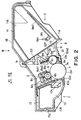
- Figure 2 is a vertical sectional view of a process cartridge.
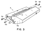
- Figure 3 is a perspective view of a process cartridge, which is for showing a disassembly or assembly process of the process cartridge.
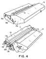
- Figure 4 is a perspective view of a process cartridge, which is for showing a disassembly or assembly process of the process cartridge.
- Figure 5 is the left side view of a process cartridge, for showing a disassembly or assembly process of the process cartridge.
- Figure 6 is the right side view of the process cartridge, for showing a disassembly or assembly process of the process cartridge.
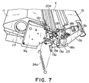
- Figure 7 is a perspective view of a unit formed by joining the cleaning and development units of the process cartridge.
- Figure 8 is a perspective view of a unit formed by joining the cleaning and development units of the process cartridge.
- Figure 9 is an exploded perspective view of the cleaning unit.
- Figure 10 is an exploded perspective view of the toner container side of the development unit.
- Figure 11 is an exploded perspective view of the partially disassembled development unit.
- Figures 12(a) and 12(b) are horizontal sectional views of the toner release opening portion of the toner holding frame portion, which show how the toner releasing opening is hermetically sealed.
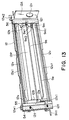
- Figure 13 is a perspective view of the developing means holding frame portion.
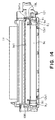
- Figure 14 is a front view of the development unit.
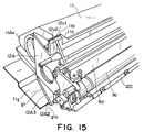
- Figure 15 is a perspective view of the front portion of the development unit prior to overhaul, as seen from diagonally above the right front.
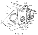
- Figure 16 is a perspective view of the rear portion of the development unit prior to overhaul, as seen from diagonally above the left front.
- Figure 17 is a perspective view of the entirety of the development unit, as seen from diagonally above the left front.
- Figure 18 is a perspective view of the rear portion (bottom side) of the development unit prior to overhaul as seen from below the left front.
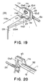
- Figure 19 is a perspective view of the top-right portion of the joint between the toner holding frame portion and developing means holding frame portion, as seen from the same direction as the direction from which the development unit is seen in Figure 16.
- Figure 20 is a perspective view of the same portion of the joint as the one illustrated in Figure 19, as seen from the direction opposite to the direction from which that joint portion is seen.
- Figure 21 is a perspective view of the inward side of the right side plate of the developing means holding frame portion prior to overhaul.
- Figure 22 is a perspective view of the front portion of the development unit after the application of sealer and the attachment of a "blow-by" prevention backup seal, as seen from diagonally above the right front (this drawing corresponds to Figure 15).
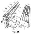
- Figure 23 is a perspective view of the rear portion of the development unit after the application of sealer and the attachment of the "blow-by" prevention backup seal, as seen from below the left front (this drawing corresponds to Figure 18).
- Figure 24 is a perspective view of the inward side of the side plate of the developing means holding frame portion after the application of seal (this drawing corresponds to Figure 21).
- Figure 25 is a perspective view of the front portion of the development unit after the application of seal, as seen from diagonally above the left front (this drawing corresponds to Figure 16).
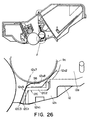
- Figure 26 is a vertical sectional view of the portion of the development unit, in which the "blow-by" prevention seal has been placed.
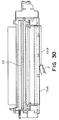
- Figure 27 is a front view of the frame portion of the development unit, from which the development roller and development blade have been removed.
- Figure 28 is a front view of the frame portion of the development unit, from which the development roller and development blade have been removed, and to which the "blow-by" prevention backup seal is being attached.
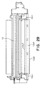
- Figure 29 is a front view of the frame portion of the development unit, from which the development roller and development blade have been removed, and to which the "blow-by" prevention backup seal is being applied.
- Figure 30 is a front view of the frame portion of the development unit, from which the development roller and development blade have been removed, and to which the "blow-by" prevention backup seal is being applied.
- Figure 31 is a perspective view of the left portion of the joint between the toner holding frame portion and developing means holding frame portion.
- Figure 32 is a perspective view of the left portion of the joint between the toner holding frame portion and developing means holding frame portion after the application of sealing agent.
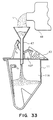
- Figure 33 is a vertical sectional view of the toner holding frame portion which is being replenished with toner.
- Figure 34 is a front view of a charging unit.
- Figure 35 is a vertical sectional view of a cleaning apparatus for removing the waste toner.
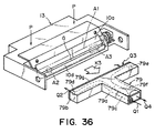
- Figure 36 is a perspective view of a toner vacuuming apparatus.
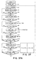
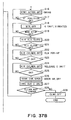
- Figure 37 is a flow chart of the waste toner removing process.
- the short direction, or "widthwise" direction of the process cartridge B means the direction in which the process cartridge B is inserted into or dismounted from the apparatus main assembly 14, and coincides with the direction in which recording medium is conveyed.
- the longitudinal direction of the process cartridge B means the direction which intersects with (approximately perpendicular to) the direction in which the process cartridge B is inserted into, or dismounted from, the apparatus main assembly 14. It intersects with (approximately perpendicular to) the direction in which recording medium is conveyed, and is parallel to the surface of the recording medium.
- Figure 1 is a drawing for describing the structure of an electrophotographic image forming apparatus (laser beam printer in accordance with the present invention.
- Figures 2 - 6 are drawings related to the process cartridge in accordance with the present invention.
- Figure 2 is a vertical sectional view of the process cartridge at a plane perpendicular to the longitudinal direction of the process cartridge
- Figure 3 is a perspective view of the process cartridge.
- Figure 4 is a perspective view of the process cartridge in a partially disassembled condition
- Figure 5 is the left side view of the process cartridge in a partially disassembled condition.
- Figure 6 is a right side view of the process cartridge in a partially disassembled condition.
- the top surface of the process cartridge B means such a surface of the process cartridge B that will be on the top side and face upward after the proper mounting of the process cartridge B into the apparatus main assembly 14, and the bottom surface of the process cartridge B means such a surface of the process cartridge B that will be on the bottom side and faces downward after the proper mounting of the process cartridge B into the apparatus main assembly 14.
- the left or right side of the process cartridge B means the left or right side of the process cartridge B as seen from diagonally above the trailing side of the process cartridge B in terms of the direction in which the process cartridge B is mounted into the apparatus main assembly 14.
- FIG. 1 is a vertical sectional view of the process cartridge at a plane perpendicular to the longitudinal direction of the process cartridge B.
- this laser beam printer A is an apparatus which forms an image on a piece of recording medium (for example, recording sheet, OHP sheet, fabric, or the like) with the use of an electrophotographic image formation process. It forms a visible image (hereinafter, "toner image”) on an electrophotographic photosensitive member (hereinafter, “photosensitive drum”) with the use of developer (hereinafter, "toner”).
- the photosensitive drum is charged by the charging means, and a latent image is formed on this charged photosensitive drum by projecting a laser beam modulated with image formation data, from an optical means, onto the charged photosensitive drum.
- This latent image is developed into a toner image by the developing means.
- the recording medium 2 stored in a sheet feeder cassette 3a is picked out and conveyed by a pickup roller 3b, and a pair of registration rollers 3e.
- the toner image formed on the photosensitive drum 7 of the process cartridge B is transferred onto the recording medium 2 by applying voltage to the transfer roller 4 as a toner image transferring means.
- the recording medium 2 is conveyed to a fixing means 5 by a conveyance guide 3f.
- the fixing means 5 comprises a driving roller 5c, and a fixing roller 5b which contains a heater 5a.
- the fixing means 5 fixes the toner image to the recording medium 2 by the application of heat and pressure.
- the recording medium 2 is conveyed through a reversal path 3j, and is discharged into a delivery tray 6, by a pair of discharging rollers 3g.
- the delivery tray 6 is located on the top side of a lid 35 for exposing or covering an opening through which the process cartridge B is mounted into, or dismounted from, the main assembly 14 of the image forming apparatus A.
- a combination of the pickup roller 3b, registration roller pair 3c, conveyance guide 3f, and discharge roller pair 3g constitutes a conveying means 3.
- the photosensitive member which has a photosensitive layer 7e as a peripheral layer is rotated, and as the photosensitive member is rotated, its peripheral surface is uniformly charged by the application of voltage to a charge roller 8 as a charging means. Then, a latent image is formed on the peripheral surface of the photosensitive drum 7 by a laser beam L projected, while being modulated with image date, upon the photosensitive drum 7 from an optical system 1 through an exposure opening le. This latent image is developed (visualized) by a developing means 9 which uses toner. More specifically, the charge roller 8 is disposed in contact with the photosensitive drum 7, and charges the photosensitive drum 7. The charge roller 8 is rotated by the rotation of the photosensitive drum 7.
- the developing means 9 develops the latent image formed on the photosensitive drum 7, by supplying the photosensitive drum 7 with toner, across the region in the development station.
- the optical system 1 comprises an unillustrated laser diode, a polygon mirror, a lens, and a reflection mirror 1d.
- the toner within the toner container 11A is sent to a development roller 9c by the rotation of a toner conveying member 9b.
- a layer of toner particles triboelectrically charged by a development blade 9d is formed on the peripheral surface of the development roller 9c, by the development blade 9d.
- Toner particles are supplied to the photosensitive drum 7, across the area within the development station from this layer of toner particles; more specifically, toner particles are transferred onto the photosensitive drum 7 in accordance with the pattern of the latent image, and as a result, a toner image, that is, a visual image, is formed.
- the development blade 9d is a member for regulating the amount by which toner is coated on the peripheral surface of the development roller 9c. Adjacent to the development roller 9c, a toner stirring member 9e for circulating the toner within the development chamber is rotationally mounted.
- the toner image formed on the photosensitive drum 7 is transferred onto the recording medium 2 by applying voltage, which is reverse in polarity compared to the toner, to the transfer roller 4. Then, the toner particles remaining on the photosensitive drum 7 are removed by a cleaning means 10. More specifically, the toner particles remaining on the photosensitive drum 7 are scraped away and are collected into a waste toner bin 10b, by an elastic cleaning blade 10a of the cleaning means 10, which is placed in contact with the photosensitive drum 7.
- a toner gathering member 10c is a member for conveying the waste toner, that is, the toner scraped down from the photosensitive drum 7 by the cleaning blade 10a, inward of the waste toner bin 10b.
- the process cartridge B is a combination of a toner holding frame portion 11, which has a toner container 11A (toner storing portion) for holding toner, a developing means holding frame portion 12 which holds developing means 9 such as the development roller 9c, and a cleaning means holding frame 13 in which the photosensitive drum 7, cleaning means 10 such as the cleaning blade 10a, and charge roller 8, are mounted.
- the toner holding frame portion 11 and developing means holding frame portion 12 are first joined together, and the cleaning means holding frame portion 13 is attached to the combination of the frame portions 11 and 12.
- the combination of the three frame portions 11, 12 and 13 is covered with a cartridge cover 15.
- the process cartridge B is removably mountable in the apparatus main assembly 14 by an operator.
- the process cartridge B is provided with the exposure opening 1e, through which a beam of light in accordance with the image formation information is projected onto the photosensitive drum 7, and a transfer opening 13n, which allows the peripheral surface of the photosensitive drum 7 to be squarely placed against the recovering medium 2. More precisely, the exposure opening le is provided on the cartridge cover 15 side, whereas the transfer opening 13n is formed between the developing means holding frame portion 12 and cleaning means holding frame portion 13.
- the process cartridge B in accordance with the present invention comprises a housing, and the aforementioned photosensitive drum 7, charge roller 8, developing means 9, cleaning means 10, and the like, which are mounted in the housing.
- the housing is a combination of the toner holding frame portion 11, developing means holding frame portion 12, and cleaning means holding frame portion 13.
- the toner holding frame portion 11 and developing means holding frame portion 12 are joined to each other, and the cleaning means holding frame portion 13 is pivotally attached.
- the combination of the three frame portions 11, 12 and 13 is covered with the cartridge cover 15.
- the process cartridge B is removably mounted in the cartridge mounting means provided within the apparatus main assembly 14.
- the process cartridge B in accordance with the present invention comprises a housing mad up of a joined combination of toner holding frame portion 11, developing means holding frame portion 12, and cleaning means holding frame portion 13, and the cartridge cover 15 which covers the joined combination.
- the structure of this housing will be described.
- the toner conveying member 9b is rotationally attached to the toner holding frame portion 11.
- the toner conveying member 9b comprises a crank 9b1, and a slider 9b2 engaged with the pin portion of the crank 9b1.
- the development roller 9c, development blade 9d, and toner stirring member 9c are attached; the toner stirring member 9c is rotationally mounted adjacent to the development roller 9c to circulate the toner within the development chamber.
- a rod antenna 9h which is positioned approximately in parallel to the longitudinal direction of the development roller 9c.
- photosensitive drum 7, charge roller 8, and various components of the cleaning member 10 are attached. Also attached to the cleaning means holding frame portion 13 is a drum shutter 18, which covers the photosensitive drum 7 to prevent the photosensitive drum 7 from being exposed to light for an extended period of time, and from coming into contact with foreign substances, forming together a first portion, or the cleaning unit C ( Figure 5), of the process cartridge B.
- the development unit D and cleaning unit C are connected to each other in such a manner that they are allowed to pivot relative to each other about a pivotal axis SC ( Figures 5 and 6), constituting the essential portion of the process cartridge B.
- the developing means holding frame portion 12 is provided with arms 19R and 19L, which are attached to the longitudinal (axial direction of development roller 9c) ends of the developing means holding frame portion 12 one for one.
- the end portions 19R1 and 19L1 of the arms 19R and 19L are provided with a rotational shaft 20R and a hole 20L, respectively ( Figure 11). These arms 19R and 19L are placed between the mutually facing side plates 13s of the cleaning means holding frame portion 13.
- One of the longitudinal ends of the cleaning means holding frame portion 13 is provided with a U-shaped slot 21R, in which the aforementioned rotational shaft 20R is fitted to be accurately positioned (see the intersectional point between the axial line of the rotational shaft and the side plate 13e).
- the hole 21L is positioned so that its axial line coincides with the line which is parallel to the photosensitive drum 7 and runs through the center of the arc, that is, the shape of the bottom portion of the U-shaped slot 21R.
- the slot 21R and hole 21L are provided in the right and left side plates 13s of the cleaning means holding frame portion 13, respectively.
- the aforementioned rotational shaft 20R is fitted in the slot 21R, and a connecting pin 22 ( Figure 5) is pressed into the hole 20L located at the end portion 19L1 of the arm 19L through the hole 21L of the side plate 13e of the cleaning means holding frame portion 13.
- the development unit D are cleaning unit C are connected to each other, being allowed to pivot relative to each other about the pivotal axis SC.
- a pair of tensional coil springs 24a and 24b are placed to keep the two units pulled toward each other to assure that the development roller 9c and photosensitive drum 7 are kept pressed toward each other.
- spacer rings 9i Figure 11
- the spacer rings 9i are kept pressed upon the photosensitive drum 7, maintaining a predetermined gap (approximately 300 ⁇ m) between the photosensitive drum 7 and development roller 9c.
- the development unit D and cleaning unit C are pivotable about the rotational shaft 20R and connecting pin 22, and in addition, the resilience of the tensional coil springs 24a and 24b makes it possible to maintain the predetermined positional relationship between the peripheral surfaces of the photosensitive drum 7 and development roller 9c.
- These tensional coil springs 24a and 24b are positioned so that they intersect with the line perpendicular connecting the interface between the photosensitive drum 7 and development roller 9c, and the pivotal axis SC about which the development unit D and cleaning unit C pivot relative to each other.
- Figures 5 and 6 are left and right side views of the process cartridge B as seen from the trailing side (indicated by an arrow mark X in Figure 1; as seen from the development unit side) in terms of the process cartridge mounting direction.
- the process cartridge B is provided with a pair of guiding means, which are attached to the cleaning means holding frame portion 13 to guide the process cartridge B when the process cartridge B is mounted into, or dismounted from, the apparatus main assembly 14.
- the guiding means are cylindrical guides 13a as guiding members.
- Each cylindrical guide 13a projects outward from the side plate of the cleaning means holding frame portion 13 so that its axial line coincides with that of the photosensitive drum 7. It doubles as a drum shaft 7a (its axial line coincides with that of photosensitive drum 7) which supports the photosensitive drum 7 at each longitudinal end of the photosensitive drum 7 ( Figure 9).
- the cylindrical guide 13a is attached by crimping to a supporting plate 13c fixed to the side plate 13s of the cleaning means holding frame portion 13 with the use of small screws.
- the cylindrical guide 13a and supporting plate 13c are formed of metallic material.
- the cartridge cover 15 covers the development unit D and cleaning unit C from above. It is provided with an opening le, which is located at the approximate center of the cartridge cover 15 in terms of the front to back direction (direction indicated by arrow marks K1 and K2 in Figure 1), penetrating the cartridge cover 15 in the vertical direction.
- the cartridge cover 15 is a portion of the process cartridge B which not only externally protects the development unit D and cleaning unit C but also makes the process cartridge B easy to handle.
- the development unit D means a unit formed by uniting the toner holding frame portion 11, which contains toner and the tone conveying member 9b, and the developing means holding frame portion 12 which contains the developing means 9.
- the cleaning unit C is a unit comprising the photosensitive drum 7, cleaning means, such as the cleaning blade, the charge roller 8, and the cleaning means holding frame portion 13 which supports the proceeding components.
- each of the side plates 13s of the cleaning means holding frame portion 13 is provided with a circular hole 13e and an elongated hole 13f.
- the major axis of the elongated hole 13f coincides with the line connecting the centers of the circular hole 13c and elongated hole 13f.
- the cartridge cover 15 is provided with through holes 15b and 15c, which are in each of the side plats 15a located one for one at the longitudinal ends of the cartridge cover 15.
- the through holes 15b and 15c are positioned in such a manner that as the cartridge cover 15 is placed in a manner to cover the united combination of the development unit D and cleaning unit C, the through holes 15b and 15c align with the circular hole 13e and elongated hole 13f of the cleaning means holding frame portion 13, allowing a small screw 15d to be screwed into the circular hole 13e through the through hole 15b, and a pin 15e to be inserted into the elongated hole 13f after being pressed through the through hole 15c.
- the cartridge cover 15 is provided with a hook 15g formed by cutting two slits upward from the bottom side of the front wall 15f, in terms of the direction in which the process cartridge B is mounted into the laser beam printer A, of the cartridge cover 15.
- this hook 15g engages, with its end portion flexing outward, in a groove 13g ( Figure 5), which is provided in the front wall of the cleaning means holding frame portion 13.
- the end portion of the hook 15g anchors itself to the bottom surface 13i of the front wall of the cleaning means holding frame portion 13, fixing the positional relation of the cartridge cover 15 relative to the cleaning unit C in terms of the longitudinal direction, front to back direction, and horizontal direction, and therefore, aligning the through holes 15b and 15c of the cartridge cover 15 with the circular hole 13e and elongated hole 13f of the cleaning means holding frame portion 13.
- process cartridge assembly is simplified.
- the process cartridge B structured as described above is mounted in the laser beam printer A illustrated in Figure 1.
- the laser beam printer A is provided with the lid 35 hinged to the apparatus main assembly 14, at a supporting point 35a located at the bottom end of the front side, in terms of the direction indicated by the arrow mark K1, of the apparatus main assembly 14.
- the lid 35 normally remains in the closed state (state represented by the solid line in the drawing), and is opened when the process cartridge B is exchanged, when it is necessary to take care of a jam of the recording medium 2, such as a piece of paper, that is, an object on which an image is formed, or in the like situations (state represented by the double dot chain line in the drawing).
- the process cartridge B is temporarily held by the open lid 35. More specifically, the lid 35 is provided with brackets 35b and 35c, which are located in the bottom portions of the lid 35, any by which the process cartridge B is supported.
- the cylindrical guides 13a of the process cartridge B fit into positioning grooves (unillustrated) located at predetermined positions within the by the unillustrated stationary portions of the apparatus main assembly 14.
- the position and attitude of the process cartridge B becomes fixed.
- the lid has not been completely closed, and as the lid 35 is fully closed, the bottom portions of the brackets 35b and 35c, which are supporting the process cartridge B, move farther downward away from the process cartridge B.
- the reflection mirror 1d is fixed to the lid 35, and as the lid 35 is completely closed, it is enabled to reflect the laser beam L toward the image formation area of the photosensitive drum 7.
- a drum gear 7b ( Figures 8 and 9) attached to one of the longitudinal ends of the photosensitive drum 7 meshes with an unillustrated driving gear provided on the apparatus main assembly side. As a result, it becomes possible for the process cartridge B to be driven from the apparatus main assembly side.
- a charge unit E comprises the charge roller 8.
- the charge roller 8 comprises a shaft 8a, and an elastic member 8a2 solidly formed around the shaft 8a. It is kept pressed upon the photosensitive drum 7. More specifically, a charging means holding frame portion 8A is fixed to the cleaning means holding frame portion 13, and a pair of charge roller bearings 8b are slidably fitted in a pair of parallel guide grooves 8A1 of the charging means holding frame portion 8A, which is located one for one at the longitudinal ends of the charging means holding frame portion 8A. The shaft 8a of the charge roller 8 is rotationally supported by this pair of bearings 8b. Between the charge roller bearings 8c and charging means holding frame portion 8A, a pair of compression coil springs 8c are placed in the compressed state.
- the positional relationship among the photosensitive drum 7, charge roller 8, and guide grooves 8A1 is such that the plane connecting the axial lines of the photosensitive drum 7 and charge roller 8 divides the guide grooves 8A1 into approximately symmetrical halves, and is parallel to the guide grooves 8A1.
- the charge unit E is attached to the cleaning means holding frame portion 13 in the following manner.
- the charging means holding frame portion 8A is placed between the two side plates 13s in the longitudinal direction of the process cartridge B, with an unillustrated joggle provided on one of the longitudinal ends of the charging means holding frame portion 8A being inserted into a hole 13s3 of one of the side plate 13s of the cleaning means holding frame portion 13.
- the snap-fit claw 13h1 of a fastener 13h is inserted into the hole 13s2 of the other side plate 13s of the cleaning means holding frame portion 13.
- an unillustrated pin is fitted in a hole in the same end of the charging means holding frame portion 8A, through a hole 13s5 of the same side plate 13s as the side plate 13s with the hole 13s2, and a pin 13h2 is engaged into the slot 13s of the side plate 13s4 in parallel to the aforementioned unillustrated pin.
- the process cartridge B is provided with the drum shutter 18 ( Figure 16) which exposes or covers the transfer opening 13n by being moved by the movement of the process cartridge B during the mounting or dismounting of the process cartridge B, respectively.
- the drum shutter 18 is structured so that when the process cartridge B is out of the apparatus main assembly 14, the drum shutter 18 remains closed to protect the image transfer area of the photosensitive drum 7.
- the drum shutter 18 is attached to the end portion of an arm 18a, and the end portion of a linking member 18b, and the arm 18a and linking member 18b are rotationally supported by the cleaning means holding frame portion 13.
- the arm 18a, linking member 18b, drum shutter 18, and cleaning means holding frame portion 13 constitute together a quadri-joint mechanism.
- the drum shutter 18 opens as the process cartridge B is inserted further into the apparatus main assembly 14, in the downward direction (direction in which lid 35 is closed), in Figure 5, after the lever 23, the base portion of which is fixed to the supporting point 18c at which the arm 18a is supported by the cleaning means holding frame portion 13, comes into contact with a stationary stopper (unillustrated) with which the apparatus main assembly 14 is provided.
- the drum shutter 18 is closed by the resiliency of a torsional coil spring 23a, as the process cartridge B is taken out of the apparatus main assembly 14.
- the torsional coil spring 23a is anchored to the supporting point 18c to keep the shutter arm 18a pressed in the clockwise direction (direction in which shutter 18 is closed).
- the brackets 35b and 35c come into contact with the cleaning means holding frame portion 13 and a portion of the cartridge cover 15. Then, as the lid 35 is rotated further, the cylindrical guide 13a comes out of the positioning guide groove (unillustrated) of the apparatus main assembly 14, and at the same time, the portion of the cartridge cover 15, which has been supported by the apparatus main assembly 14, separates upward from the unillustrated stationary process cartridge supporting portion of the apparatus main assembly 14. Then, after the lid 35 is fully opened, the process cartridge B is pulled diagonally upward in the rightward direction of Figure 1. As the process cartridge B is pulled in the above described direction, the process cartridge B comes out of the apparatus main assembly 14. As for the shutter 18, it is rotationally moved by the resiliency of the torsional coil spring 23a to cover the transfer opening 13n, as the process cartridge B is moved upward in the apparatus main assembly 14.
- the helical gear 7n meshes with a gear (unillustrated) provided on the apparatus main assembly side.
- the helical gear 7n and the unillustrated gear on the apparatus main assembly side share the same rotational axle.
- the drum gear 7b and helical gear 7n are opposite in the helix direction. Therefore, the thrusts which apply to the gears 7b and 7n are the same in direction with respect to the photosensitive drum 7.
- a referential code 9k in Figure 1 designates a helical gear attached to one of the longitudinal ends of the development roller 9c.
- the helical gear 9k meshes with the aforementioned helical drum gear 7b, so that the force for rotating the development roller 9c is transmitted to the helical gear 9k from the helical drum gear 7b.
- the toner holding frame portion is a single piece component. Prior to the welding of the cover film plate 53, to which a sealing film 51 has been pasted, to the toner holding frame portion 11, the toner conveying member 9b is assembled into the toner holding frame portion 11, and a coupling lle is attached to the end portion of the toner conveying member 9b through a hole llel from outward side of the hole 11c1 (state illustrated in Figure 10).
- the hole 11e1 is in one of the side plates of the toner holding frame portion 11 at the longitudinal end.
- the side plate with the hole 11e1 is also provided with a circular hole 11d ( Figure 6) through which toner is filled; the hole llel and toner filling hole lld are next to each other.
- the toner holding frame portion 11 is provided with a hole lli through which toner is conveyed from the toner holding frame portion 11 to the developing means holding frame portion 12.
- the cover film plate 53 with a sealing film 51 is welded in a manner to block this hole lli. Therefore, toner is filled through the toner filling hole 11d, and then, the toner filling hole 11d is plugged with a toner cap 11f, comprising a toner unit J.
- the toner cap 11f is formed of soft material such as polyethylene or polypropylene, and is pressed into the toner filling hole 11d of the toner holding frame portion 11 so that it does not become unplugged.
- the toner unit J is welded to the developing means holding frame portion 12, which will be described later, with the interposition of the cover film plates 53, by ultrasonic waves, forming the development unit D.
- selection of the method for joining them is not limited to ultrasonic welding;they may be joined by gluing, snap-fitting, or the like.
- the toner conveying member 9b comprises the crank 9b1, which is formed of ferric rod or the like; approximately 3 mm in diameter, and the slider 9b2 which is reciprocally moved by the crank pin of the crank 9b1.
- One of the journal portions of the crank 9b1 of the toner conveying member 9b is fitted a hole in the inward side, that is, the side facing the opening 11i, of the end plate of the tone holding frame portion 11, and the other journal portion is fastened to the coupling 11e.
- the portion of the toner holding frame portion 11, which is joined with the corresponding portion of the developing means holding frame portion 12, is provided with the opening 11i through which toner is sent from the toner holding frame portion 11 into the developing means holding frame portion 12.
- the opening 11i is surrounded with a flange 11a with a flat surface 11k.
- the cover film plate 53 is welded. Therefore, the surface 11k of the flange 11a is provided with a ridge 11h for welding the cover film plate 53 to the toner holding frame portion 11.
- the ridge 11h extends in a manner to surround the opening 11i.
- the shutter of the developing means holding frame portion 12, which is joined with the corresponding surface of the toner holding frame portion 11, constitutes an approximately flat surface 12u, which is provided with a pair of triangular ridges 12v which extend along the longitudinal edges of the flat surface 12u. More specifically, the triangular ridges 12v are on the flat surface 12u1, which is slightly elevated from the mid section of the flat surface 12u.
- the toner holding frame portion 11 to which the cover film plate 53 has been welded, and the developing means holding frame portion 12 are welded by ultrasonic waves, along their longitudinal edges, with the ridges 12v of the developing means holding frame portion 12 kept pressed upon the cover film film plate 53.
- the cover film plate 53 which is welded to the toner holding frame portion 11 is provided with two holes 53c, and the flange 11a of the toner holding frame portion 11 is provided with holes 11c.
- the holes 53c of the cover film plate 53 align with the holes 11c of the flange 11a.
- the cover film plate 53 is provided with a hole 53b (smaller than the aforementioned hole 11i) which corresponds to the hole 11i. This hole 53b is blocked by the sealing film pasted to the cover film plate 53.
- the sealing film is easy to tear in its longitudinal direction. More specifically, the sealing film is pasted to the cover film plate 53, along the surrounding four edges of the hole 53b.
- the sealing film 51 is extended out of the process cartridge B; the sealing film 51 is rendered long enough to be pasted to the cover film plate 53 from one longitudinal end to the other to cover the hole 53b, doubled back to the starting end, and extended beyond the starting end to be exposed from the process cartridge B, through the interface between an elastic sealing member 54 ( Figures 12 and 13) with which the developing means holding frame portion 12 is provided, and the cover film 53 ( Figure 12).
- the elastic member 54 is formed of felt or the like material and is pasted to the developing means holding frame portion 12, on the flat surface which is located at one of the longitudinal ends of the developing means holding frame portion 12. This flat surface is the counterpart of the cover film plate 53 fixed to the toner holding frame portion 11.
- the flange 11a of the toner holding frame portion 11 is provided with a round hole 11r and a square hole 11q, into which a cylindrical joggle 12w1 and a square joggle 12w2 of the developing means holding frame portion 12, fit (Figure 10).
- the joggle 12w1 tightly fits in the round hole 11r, whereas the joggle 12w2 loosely fits in the square hole 11q, being afforded a small amount of tolerance in the longitudinal direction.
- the sealing members 54 and 56 are adhered to the flat surface 12u, extending beyond the ridge 12v in terms of the widthwise direction of the process cartridge B.
- the developing means holding frame portion 12 is provided with a pair of joggles 12f, which loosely fit in the aforementioned hole 53c of the cover film plate 53 and hole 11c of the toner holding frame portion 11.
- the sealing member 54 is penetrated by these joggles 12f.
- the toner holding frame portion 11 and developing means holding frame portion 12 are assembled as independent units before they are joined. Thereafter, the cylindrical positioning joggle 12w1 and square positioning joggle 12w2 of the developing means holding frame portion 12 are fitted into the round positioning hole 11r and square positioning hole 11q of the toner holding frame portion 11, and the toner holding frame portion 11 and developing means holding frame portion 12 are pressed against each other, causing the sealing members 54 and 56 to be compressed. As the sealing members 54 and 56 are compressed, the pair of ridges 12v, which are integrally formed parts of the developing means holding frame portion 12 and extend on the flat surface 12u along the longitudinal edges of the developing means holding frame portion 12, one for one, are pressed upon the surface of cover film plate 53. It should be noted here that the aforementioned pair of joggles 12f are positioned across the path of the sealing film 51, being separated by a distance equal to the width of the sealing film 51, to regulate the sealing film 51 as the sealing film 51 is pulled through.
- the sealing film 51 pasted to the surface of the cover film plate 53 can be smoothly pulled out from between the two frame portions 11 and 12, simply by applying force to the cover film 51 in a manner to pull it. Further, the path between the cover film plate 53 and developing means holding frame portion 12, through which the sealing film 51 is pulled out, is provided with the aforementioned pair of joggles 12f, which are positioned across the path, with the provision of a distance equal to the width of the sealing film 51. Therefore, the sealing film 51 can be pulled out in a straight line.
- plastic for example, polystyrene, ABS resin (acrylonitrile/ butadiene/styrene copolymer), polycarbopate, polyethylene, polypropylene, polyphenylene oxide, or the like, is usable.
- Figure 11 is an exploded perspective view of the developing means holding frame portion 12, which shows how developing means components are assembled into the developing means holding frame portion 12.
- Figure 13 is a perspective view of the portion of the developing means holding frame portion 12, which faces the toner holding frame portion 11.
- the development roller 9c, development blade 9d, toner stirring member 9e, and rod antenna 9h for detecting the remaining amount of toner are assembled.
- the development blade 9d comprises an approximately 1 - 2 mm thick metallic plate 9d1, and a piece of urethane rubber 9d2 fastened to the metallic plate 9d1 with the use of hot-melting, double-sided tape, or the like. It regulates the amount by which toner is coated on the peripheral surface of the development roller 9c.
- the developing means holding frame portion 12 is provided with two blade anchoring flat surfaces 12i, as blade mounts.
- the flatness of these flat surfaces 12i are regulated to approximately 0.05 mm.
- Each flat surface 12i is provided with a joggle 12i1 and a hole 12i2 with female threads.
- the two flat surfaces 12i are located at the longitudinal ends of the developing means holding frame portion 12, one for one; the flat surface 12i, projection 12i1, and hole 12i2 with female threads, on the left side of the developing means holding frame portion 12, and the flat surface 12i, projection 12i1, and hole 12i2 with female threads, on the right side of the developing means holding frame portion 12, are symmetrically positioned relative to each other.
- the joggle 12i1 is fitted into the hole 9d3 of the metallic plate 9d1. Then, the metallic plate 9d1 is fastened to the flat surface 12i by putting an unillustrated small screw through the screw hole 9d4 of the metallic plate 9d1, and screwing the small screw into the aforementioned hole 12i2 with female threads.
- the developing means holding frame portion 12 is provided with an elastic seal 12s formed of MOLTOPREN, or the like.
- the elastic seal 12s is pasted to the developing means holding frame portion 12, along the longitudinal edge corresponding to the top edge of the metallic plate 9d1, to prevent toner invasion. It is kept compressed by the metallic plate 9d1.
- the developing means holding frame portion 12 is provided with two elastic seals 12s1, each of which is pasted to the developing means holding frame portion 12 and extends in the widthwise direction of the developing means holding frame portion 12 from the corresponding longitudinal end of the elastic seal 12s to the cylindrical surface 12j, along which the development roller 9c fits.
- Pasted to the mandible-like portion 12h of the developing means holding frame portion 12 is a thin elastic seal 12s2, which remains in contact with the development roller 9c at the generatrix portion of the development roller 9c ( Figure 2).
- the metallic plate 9d1 of the development blade 9d is bent 90 deg. at one of the longitudinal ends, forming an end portion 9dla This portion 9dla equalizes the metallic plate 9d1 and development roller 9c in electrical potential, by contacting a development bias contact 121 ( Figure 14) supported by the aforementioned arm 19L.
- This arrangement is made for the following reason. That is, the toner amount is determined by detecting the change in the electrostatic capacity between the toner amount detection rod antenna 9h and development roller 9c, and therefore, this electrostatic capacity must be prevented from irregularly fluctuating due to the influence from the metallic plate 9d1.
- the development roller unit G comprises: (1) the development roller 9c having a sleeve flange 9a attached to one of its longitudinal ends; (2) two spacer rings 9i for keeping constant the distance between the peripheral surfaces of the development roller 9c and photosensitive drum 7; (3) two development roller bearings 9j for precisely positioning the development roller 9c relative to the developing mean holding frame portion 12, one of the roller bearings 9j being fitted in a portion of the sleeve flange 9a smaller in diameter than the development roller 9c, and the other being fitted in the sleeve cap 9o; (4) a sleeve cap 9o which is an integrally formed part of one of the spacer rings 9i, or joined with one of the spacer rings 9i, and is fitted over one of the longitudinal ends of the development roller 9c to prevent the electrical leak which otherwise would occur between the cylindrical aluminum base A1 of the photosensitive drum 7 and the cylindrical aluminum portion of the development roller 9c; (5) the development roller gear 9 (helical gear) for rotating
- This development roller unit G is attached to the development roller mount of the developing means holding frame portion 12. More specifically, each longitudinal end portion of the development roller unit G is fitted in the roughly semicylindrical portion 19a of the arm 19R (19L), with the rotation control projection 9j1 of each development roller bearing 9j aligned with the recess 12p of the corresponding longitudinal end portion of the developing means holding frame portion 12, and the arms 19R and 19L are attached to the developing means holding frame portion 12 with the use of screws 12d ( Figures 5 and 6).
- the development roller unit G when attaching the development roller 9c to the developing means holding frame portion 12, the development roller unit G is assembled first, and then, the assembled development roller unit G is attached to the developing means holding frame portion 12 with the interposition of the arms 19R and 19L. Using this assembly procedure improves assembly efficiency compared to an assembly procedure in which the development roller 9c in directly attached to the developing means holding frame portion 12.
- the magnet 9g is inserted into the development roller 9c, and the elastic development contact 91(e1) is fitted in the development roller 9c.
- the sleeve cap 9o is fitted over one of the longitudinal ends of the development roller 9c, and the two spacer rings 9i are fitted one for one around the longitudinal ends of the development roller 9c.
- the two development roller bearings 9j for supporting the development roller 9c are attached one for one to the longitudinal ends of the development roller 9c, and the development roller gear 9k is attached to one of the longitudinal ends of the development roller 9c, on the outward side of the bearing 9j.
- a shaft portion 9g1 of the cylindrical magnet 9g which is given a D-shaped cross section, is projecting from the longitudinal end of the development roller 9c, to which the development roller gear 9k has been attached, whereas the other shaft portion 9g2 of the cylindrical magnet 9g is projecting from the other longitudinal end of the development roller 9c.
- These shaft portions 9g1 and 9g2 with a D-shaped cross section are fitted in D-shaped holes 19b cut in the arms 19R and 19L (hole 19b of arm 19L is not illustrated).
- the rod antenna 9h for detecting the remaining amount of toner will be described.
- the rod antenna 9h is bent at the end portion, assuming the shape of a crank.
- the crank portion 9h1 comes into contact with a toner amount detection contact (unillustrated) attached to the apparatus main assembly 14, establishing electrical connection to the apparatus main assembly 14.
- the developing means holding frame portion 12 is provided with a groove 12k and a groove 12k1, which have a V-shaped cross section, and are in the side wall located at one of the longitudinal ends of the opening 12P.
- the grooves 12k and 12k1 are connected to each other, and the groove 12k is L-shaped and leads to the outward side of the developing means holding frame portion 12.
- the rod antenna 9h is fitted in these grooves 12k and 12k1, and an unillustrated plug is fitted in a groove 19k with a V-shaped cross section, with the addition of adhesive, to secure the rod antenna 9h in the grooves 12k and 12k1.
- the rod antenna 9h is supported in the grooves 12k and 12k1 with a V-shaped cross section, being thereby accurately positioned.
- the toner stirring member 9e is in the form of a crank, and stirs toner by rotating. It is located in the toner path through which the toner stored in the toner container 11A is moved to the development roller 9c, as well as in the adjacencies of the development roller 9c and rod antenna 9h.
- one of the end portions of the toner stirring member 9e is inserted into the developing means holding frame portion 12 through a through hole 12t provided in the side plate 12A of the developing means holding frame portion 12, located on the side opposite to the side from which the external contact point 9h1 of the aforementioned rod antenna 9h is extending outward from the developing means holding frame portion 12.
- the diameter of the through hole 12t is large enough for the crank portion of the toner stirring member 9e to be put through the side plate 12A.
- journal portion, or the end portion, of the inserted portion of the toner stirring member 9e is put through an unillustrated through hole provided in the side plate 12B of the developing means holding frame portion 12, located on the side opposite to the side where the side plate 12A of the developing means holding frame portion 12 is located. Thereafter, the unillustrated through hole of the side plate 12B is closed by melting the side plate 12B from the outward side of the side plate 13B, or by screwing a small screw into the hole. After the stirring member 9e is inserted into the developing means holding frame portion 12 as described above, a stirring gear 9m ( Figure 16) is fitted in the through hole 12t.
- the crank arm 9e2 of the toner stirring member 9e is fitted in the slit 9m1 of the gear 9m, which is located at the inward end of the gear 9m and extending in the axial direction of the gear 9m, as shown in Figure 13.
- the journal portion 9c1 of the toner stirring gear 9e is fitted in the center hole of the gear 9m, located at the inward end of the slit 9m1, to support the toner stirring member 9e by the developing means holding frame portion 12.
- the outward disengagement of the stirring gear 9m from the developing means holding frame portion 12 is prevented by placing the flat portion 19c of the arm 19R in a manner to overlap with the stirring gear 9m in terms of the longitudinal direction of the process cartridge B.
- the side plate 12A of the developing means holding frame portion 12 on the side from which the aforementioned toner stirring member 9e is inserted extends beyond the side plate of the toner holding frame portion 11, and covers the toner cap having been pressed into the toner holding frame portion 11.
- the side plate 12A is provided with a hole 12x, in which a toner conveyance gear 9s, that is, the output gear of a gear box 9q for transmitting driving force to the toner conveying member 9b and toner stirring member 9e, is fitted with the presence of a certain amount of play ( Figure 11).
- the toner conveyance gear 9s coupled with the coupling 11e ( Figure 10), which is attached to one of the longitudinal ends of the toner conveying member 9b and is rotationally supported by the toner holding frame portion 11, to transmit driving force to the toner conveying member 9b.
- This gear box 9q is attached to the side plate 12A of the developing means holding frame portion 12 by snap-fitting an arm 9q1 provided with a claw which extends toward the side plate 12A, into a hole 12Aa of the side plate 12A.
- an input gear 9n which meshes with the development roller gear 9k so that driving force is transmitted to the input gear 9n from the development roller 9k.
- the stirring gear 9m meshes with an output gear 9r, that is, the other gear of the gear box 9q.
- the development roller gear 9k rotates by receiving driving force from the drum gear 7b meshed with the development roller gear 9k
- the input gear 9n rotates, rotating thereby the toner conveying gear 9s connected to the input gear 9n through a gear train.
- driving force is transmitted to the toner conveying member 9b.
- the output gear 9r rotates the toner stirring gear 9m, and as a result, the toner stirring member 9e rotates.
- the downwardly facing surface of the mandible-like portion 12h of the developing means holding frame portion 12 doubles as a conveyance guide for the recording medium 2 such as a sheet of paper. Further, in order to increase the rigidity of the developing means holding frame portion 12, the developing means holding frame portion 12 is provided with a substantial number of ribs (unillustrated).
- a referential code 12P designates a hole, which extends in the longitudinal direction of the developing means holding frame portion 12. This hole 12P aligns with the hole 11i of the toner holding frame portion 11, and the hole 53b of the cover film plate 53, after the toner holding frame portion 11 and developing means holding frame portion 12 are joined with the interposition of the cover film plate 53.
- the aforementioned toner stirring member 9e and rod antenna 9h extend from one longitudinal end of the hole 12P to the other.
- the development roller mount, side plate 12A (gear box 9q mount), development blade mount (blade mounting flat surface 12i), antenna 9h mount, toner stirring member mount, and the like, of the developing means holding frame portion 12 are formed as integral parts of the developing means holding frame portion 12.
- the material for the developing means holding frame portion 12 is the same as the aforementioned material for the toner holding frame portion 11.
- Figure 11 gives a perspective view of the inward side of the arm 19R which is to be attached to the developing means holding frame portion 12, on the side from which the process cartridge B is driven (hereinafter, “driven side"), as well as a perspective view of the outward side of the arm 19L which is to be attached to the developing means holding frame portion 12, on the side opposite to the driven side (hereinafter, “non-driven side”).
- the various components of the development roller unit G which are in the state shown in Figure 11, are assembled into the development roller unit G.
- the arms 19R and 19L are attached to the developing means holding frame portion 12 in a manner to sandwich the assembled development roller unit G from the right and left longitudinal ends of the development roller unit G, completing the development unit D.
- the projection 9j1 of each bearing 9j is fitted in the recess 12p in such a manner that the peripheral surface of the development roller 9c is supported by two seals 12s1, and the roughly semicylindrical portions 19a of the arms 19R and 19L are fitted with the corresponding semicylindrical surfaces 12j of the developing means holding frame portion 12.
- each bearing 9j fits with the internal surface of the corresponding roughly semicylindrical portion 19a.
- the two bearings 9j are supported by the developing means holding frame portion 12 with the interposition of the arms 19R and 19L, one for one.
- the development bias contact 121 is attached to the arm 19L by snap-fitting.
- Each of the arms 19R and 19L is fastened to the developing means holding frame portion 12 by screwing the small screw 12d ( Figure 5), with the joggle 12g and projection 12c of the developing means holding frame portion 12 fitted in the hole 19c1 and slot 19c2 of the flat portion 19c of the corresponding arm.
- the arm 19L is fitted with the development bias contact 121. More specifically, a joggle provided on the arm 19L, on the back side with respect to Figure 11, is pressed into the slot of the contact 121.
- the external contact point 121c of the development bias contact 121 is in contact with an unillustrated development contact of the apparatus main assembly 14, and receives from the apparatus main assembly 14 the development bias to be applied to the development roller 9c. After being received from the apparatus main assembly 14, the development bias is applied to the development roller 9c through the development bias contact 121 and elastic development contact 91(e1).
- a toner detection contact 122 and the external contact point 9hl are electrically in contact with an unillustrated toner detection contact of the apparatus main assembly 14, and another unillustrated contact of the apparatus main assembly 14, respectively.
- electrical signals generated in accordance with the electrostatic capacity which changes in response to the change in the amount of the toner between the development roller 9c and rod antenna 9h are transmitted to an unillustrated contact of the apparatus main assembly 14 from the rod antenna 9h.
- the control section unillustrated
- the process cartridge B is provided with a plurality (four) of electrical contacts: (1) an electrically conductive ground contact 119 which is electrically connected to the photosensitive drum 7 to ground the photosensitive drum 7 through the apparatus main assembly 14 (one of the two cylindrical guides 13a doubles as the contact 119); (2) an electrically conductive charge bias contact 120 which is electrically connected to the charge roller shaft 8a to apply charge bias to the charge roller 8 from the apparatus main assembly 14; (3) an electrically conductive development bias contact 121 which is electrically connected to the development roller 9c to apply development bias to the development roller 9c from the apparatus main assembly 14; (4) the toner remainder amount detection contact 9h1, that is, the external contact portion 9h1 of the rod antenna 9h, for detecting the remaining amount of toner.
- the ground contact 119 and charge bias contact 120 belong to the cleaning means holding frame portion 13
- the development bias contact 121 and toner remainder amount detection contact 9h1 belong to the development means holding frame portion 12 (more specifically, arm 19L). Further, the toner remainder amount detection contact 9h1 doubles as a process cartridge detection contact for enabling the apparatus main assembly 14 to detect whether or not the process cartridge B is in the apparatus main assembly 14.
- the electrical conductivity of the ground contact 119 is realized by using an electrically conductive substance as the material for the drum shaft 7a of the photosensitive drum 7, or by inserting an electrically conductive member into the drum shaft 7a, with the use of insert-molding, during the formation of the drum shaft 7a.
- the drum shaft 7a was formed of metallic material such as iron.
- the other contacts 120 and 121 are formed of approximately 0.1 - 0.3 mm thick plate of electrically conductive material (for example, stainless steel, phosphor bronze, and the like), and are intricately extended outward from the inward side of the process cartridge B.
- the charge bias contact 120 is positioned so that it is exposed from the side plate of the cleaning unit C, on the non-driven side, whereas the development bias contact 121 and toner remainder amount detection contact 9h1 are positioned so that they are exposed from the side plate of the development unit D, on the non-driven side.
- the charge bias contact 120 is virtually horizontally arranged relative to the ground contact 119, and is attached to the end of the arm 8A2 which is integral with the charging means holding frame portion 8A which supports the charge roller 8 ( Figure 5).
- the charge bias contact 120 is electrically in contact with the charge roller 8 through an electrically conductive member which is in contact with the charge roller shaft 8a.
- the rod antenna 9h is positioned so that it extends along the development roller 9c across the entirety of the development roller 9c, holding a predetermined distance from the development roller 9c.
- the electrostatic capacity between the rod antenna 9h and development roller 9c changes in response to the amount of the toner between the two components.
- the changes in this electrostatic capacity are detected as changes in electrical potential by the control portion (unillustrated) of the apparatus main assembly 14 to detect the amount of the toner remainder.
- the toner remainder amount means the amount of toner which is between the development roller 9c and rod antenna 9h and generates a certain amount of electrostatic capacity. Thus, it can be detected by detecting the amount of the electrostatic capacity between the development roller 9c and rod antenna 9h that the toner remainder amount within the toner container 11A has reduced to a certain amount. More specifically, that the toner remainder amount within the toner container 11A has reduced to a predetermined amount is determined by the control portion of the apparatus main assembly 14 by detecting through the toner detection contact 120 that the amount of the electrostatic capacity has reached the first predetermined value.
- the apparatus main assembly 14 Detecting that the electrostatic capacity has reached the aforementioned first predetermined value, the apparatus main assembly 14 issues a process cartridge exchange warming (for example, turning on-and-off of a lamp, or sound generation by buzzer). Further, the control portion detects, by detecting the predetermined second value smaller than the aforementioned predetermined value representing the predetermined toner remainder amount, that the process cartridge B has been mounted into the apparatus main assembly 14. If the control portion does not detect that the process cartridge B has been mounted in the apparatus main assembly 14, it does not allow the apparatus main assembly 14 to start an image formation operation. Incidentally, the control portion may be configured so that it issues a no-carriage warming (for example, turning on-and-off of a lamp) in such a case.
- the housing of the process cartridge B in this embodiment comprises a joined combination of the toner holding frame portion 11, developing means holding frame portion 12, and cleaning means holding frame portion 13. Next, the structure of this housing will be described.
- the toner holding frame portion 11 includes the toner container 11A, and to the toner holding frame portion 11, the toner conveying member 9b is attached.
- development roller 9c and development blade 9d are attached to the developing means holding frame portion 12.
- the toner stirring member 9e is also rotationally attached to the developing means holding frame portion 12 .
- the toner holding frame portion 11 and developing means holding frame portion 12 are welded to each other to form a monolithic frame portion for the development unit D ( Figure 8).
- the cleaning means holding frame portion 13 Attached to the cleaning means holding frame portion 13 are the photosensitive drum 7, the charge roller 8, and the various components of the cleaning means. Also attached to the cleaning means holding frame portion 13 is the drum shutter 18 ( Figure 5), which covers the photosensitive drum 7 to protect it when the process cartridge B is out of the apparatus main assembly 14. Together, they constitute the cleaning means unit C ( Figure 8).
- the development unit D and cleaning unit C are joined to form the process cartridge B.
- the rotational shaft 20R of the development unit D is fitted in the slot 21R of the cleaning unit C, while fitting the flat portions 19R1 and 19L1 of the arms 19R and 19L with the inward sides of the corresponding side plates 13s of the cleaning unit C.
- the end portion of the connecting pin 22, which has been pressed into the hole 13s4 of the side plate 13s, is slid into the hole 20L of the arm 19L.
- the end portions of the tensional coil spring 24b are attached, one for one, to a spring anchor 13y, that is, an outward projection formed as an integral part of the cleaning means holding frame portion 13, and a spring anchor 19z, that is, an outward projection formed as an integral part of the arm 19L.
- the tensional coil spring 24a are anchored between a spring anchor 12z, that is, an outward projection formed as an integral part of the side plate 12A on the downstream side in terms of the process cartridge mounting direction, and a spring anchor 13z which projects in the longitudinal direction from the bottom wall of cleaning means holding frame portion 13.
- a spring anchor 12z that is, an outward projection formed as an integral part of the side plate 12A on the downstream side in terms of the process cartridge mounting direction
- a spring anchor 13z which projects in the longitudinal direction from the bottom wall of cleaning means holding frame portion 13.
- the drum gear 7b and the helical gear 9k of the development roller 9c are meshed with each other.
- the development roller 9c is rotationally driven by the photosensitive drum 7.
- the rotational shaft 20R located at the joint portion is positioned so that the angle formed by the transverse line of action between the mutually meshed gears of the photosensitive drum 7 and development roller 9c, and the line connecting the pitch point between the two gears and pivotal axis SC, falls on the encroachment side. Therefore, rotational moment is effected upon the development unit D also by the rotating of the development roller 9c, and as a result, the spacer rings 9i fitted around the development roller 9c are pressed upon the photosensitive drum 7 by the development roller 9c.
- the spacer rings 9i of the development roller 9c are kept pressed upon the photosensitive drum 7 by the self-weight of the development unit D, the resiliency of the tensional coil springs 24a and 24b, the rotational driving of the gears of the photosensitive drum 7 and development roller 9c, and therefore, the gap between the photosensitive drum 7 and development roller 9c is kept constant (in this embodiment, approximately 300 ⁇ m) to always assure good image quality.
- the cartridge cover 15 is removed.
- the process cartridge B to be overhauled is set in an air duct (unillustrated). Then, the toner particles and dust adhering to the surface of the process cartridge B are removed by blowing air upon the process cartridge B.
- the small screws 15d which were put through the holes 15b of the left and right side plates 15a of the cartridge cover 15 and screwed into the round holes 13e of the cleaning means holding frame portion 13, are removed with the use of a screwdriver, and the pins 15e, which were put through the holes 15c of the same side plats15a and inserted into the elongated holes 13f, are pulled out with the use of a pliers or the like.
- the cartridge cover 15 is pulled upward while keeping the hook 15g disengaged outward from the cleaning means holding frame portion 13 with the use of a fingertip or the like. As the cartridge cover 15 is pulled upward as described above, it comes off from the joint combination of the cleaning unit C and development unit D.
- each pin 15e is shaped like a flange with a central recess, and therefore, the pin 15e can be removed by pulling and twisting while holding this flange-like portion with the use of a radio pliers, for example.
- the pin 15e is formed of resin, and its end portion is provided with a catch. However, this catch, and the flange-like portion which is gripped by a radio pliers, are easy to break, and therefore, the old pins 15e are replaced with brand-new ones.
- the tensional coil spring 24a and 24b provided to cause the photosensitive drum 7 and development roller 9c to press against each other as shown in Figures 5 and 6 are removed. More specifically, the tensional coil spring 22a is disengaged from the spring anchors 12z and 13z of the developing means holding frame portion 12 and cleaning means holding frame portion 13, respectively. The tensional coil spring 22b is disengaged from the spring anchor 19z and 13y of the arm 19L and cleaning means holding frame portion 13, respectively. The removal tensional coil springs 24a and 24b are tested, and if they meet a predetermined standard, they are used for overhauling.
- the rotational shaft 20R which projects outward from the arm 19R is lifted out of the U-shaped slot 21R of cleaning unit C illustrated in Figures 8 and 9.
- the development unit D is disengaged from the connecting pin 22 by moving the cleaning unit C and development unit D relative to each other in the longitudinal direction. It should be mentioned here that the cleaning unit C and development unit D may be separated by pulling out the connecting pin 22 with the use of a radio pliers or the like.
- the steps described above complete the process for separating the first and second units of the process cartridge B removably mountable in the apparatus main assembly 14.
- the first unit is the cleaning unit C which supports the photosensitive drum 7
- the second unit is a combination of the developing means holding frame portion 12 which supports the development roller 9c, and the toner holding frame portion 11 having the toner container 11A as a developer holding portion for storing the toner as developer used for development by the development roller 9c.
- the first and second units are connected in such a manner that they are allowed to pivot relative to each other.
- the development roller 9c is rotationally supported by the development roller bearings 9j. More specifically, the sleeve flange 9a fitted in one end of the development roller 9c is rotationally supported by a developer roller bearing 9jR, that is, one of the two developer roller bearings 9j, and the sleeve cap 9o fitted over the other end of the development roller 9c is rotationally supported by the developer roller bearing 9jL, or the other of the two developer roller bearings 9j.
- the development blade 9d is attached to the developing means holding frame portion 12 along the upper edge of the hole 12P of the developing means holding frame portion 12.
- the arms 19R and 19L are fixed to the longitudinal ends of the developing means holding frame portion 12 with the use of the screws 12d, the end portions of the partly flattened cylindrical shafts 9g1 and 9g2 which project one for one from the ends of the magnet 9g placed within the development roller 9c, being fitted one for one in the holes 19b ( Figure 11), in the form of a partly flattened cylinder, of the arms 19R and 19L.
- the development roller 9c is rotationally supported by the development roller bearings 9jR and 9jL, and the ends of the partly flattened cylindrical shafts 9g1 and 9g2 of the magnet 9g are supported by the arm 19R and 19L while being accurately positioned.
- the arms 9q1 that is, snap-fitting claws, which are projecting through the hole 12Aa of the side plate 12A, are flexed by inserting a ratio pliers or the like between the side plate 12A and toner holding frame portion 11, and then, the gear box 9q is separated from the side plate 12A by pulling the gear box 9q outward in the longitudinal direction of the process cartridge B.
- the partly flattened cylindrical shafts 9gl and 9g2, that is, the longitudinal end portions of the magnet 9g, are freed from the arms 19R and 19L.
- the development roller unit G is moved out of the developing means holding frame portion 12 in the direction perpendicular to the axial direction of the development roller 9c.
- the development roller bearings 9jR and 9jL are removed together with the development roller unit G.
- the unillustrated screws which were put through the screw holes 9d4 of the development blade 9d and were firmly screwed in the holes 12i2 with female threads in the flat blade mount 12i of the developing means holding frame portion 12, are removed.
- the development blade 9d is separated from the developing means holding frame portion 12 in the direction to disengage the left and right positioning joggles 12i1 provided on the flat blade mount 12i of the developing means holding frame portion 12, from the positioning holes 9d3 of the development blade 9d.
- the sealing film 51 is repaired during the overhauling of the recycled process cartridge B, the overhauled process cartridge B will be like a brand-new process cartridge. In this embodiment, however, the sealing film 51 is not repaired. It is unnecessary to replace the old sealing film 51 with a fresh one, because all that is necessary is to render the recycled process cartridge airtight enough to prevent toner from leaking out of the process cartridge.
- the toner holding frame portion 11 and developing means holding frame portion 12 are joined to each other with the interposition of the cover film plate 53. Thus, while the hole 11i of the toner holding frame portion 11 remains sealed with the sealing film 51, toner does not leak. Since the toner holding frame portion 11 and developing means holding frame portion 12 are left joined to each other during the overhauling, it is impossible to seal the hole 11i of the toner holding frame portion 11 with a new sealing film 51.
- the flat surface 11k of the flange 11a of the toner holding frame portion 11 is provided with the ridge 11h which extends surrounding the hole 11i. Since this ridge 11h and cover film plate 53 were welded to each other, it does not occur that the toner leaks outward from between the toner holding frame portion 11 and cover film plate 53.
- the longitudinal end portions of the cover film plate 53 are in contact with the elastic seals 54 and 56 pasted to the developing means holding frame portion 12 one for one.
- the elastic seals 54 and 56 are formed of elastic substance such as felt, and remain pressed upon the cover film plate 53. Therefore, toner does not leak while the process cartridge B is mounted into, or dismounted from, the apparatus main assembly 14. However, there is a possibility that if the process cartridge B is subjected to a certain type of impact during process cartridge shipment, toner could leak. Thus, this possibility has to be eliminated.
- the gear box 9q is attached to the right side walls of the toner holding frame portion 11 and developing means holding frame portion 12. If the gear box 9q is disengaged from the developing means holding frame portion 12, it is possible to seal the joint between the right ends of the toner holding frame portion 11 and developing means holding frame portion 12. This sealing operation is possible while the development roller unit G remains attached to the developing means holding frame portion 12. However, since adhesive sealant is used, it is better to carry out the operation after the removal of the development roller unit G and development blade 9d.
- the bottom portion of the toner holding frame portion 11 is provided with a bottom flange 11g, which is an integrally molded part of the toner holding frame portion 11 and extends outward in the longitudinal direction of the toner holding frame portion 11.
- This bottom flange 11g is perpendicular to the flange 11a, that is, the flange on the front side, of the toner holding frame portion 11, and also to the side plate 11As of the toner holding frame portion 11.
- This bottom flange 11g of the toner holding frame portion 11, and the triangular bottom flange 12A2, that is, an integral part of the bottom portion of the side plate 12A of the developing means holding frame portion 12, are parallel to each other, and there is a gap g1, or a first gap, between the two flanges 11g and 12A2, and opens outward from between the edge of the bottom flange 12A2 of the developing means holding frame portion 12, and the bottom flange 11g of the toner holding frame portion 11.
- gap g2 there is another gap g2, or the second gap, between the edge 11g1 of the bottom flange 11g of the toner holding frame portion 11, and the flat surface 12u1 of the developing means holding frame portion 12.
- the gap g1 and g2 are continuous; the portion of the gap g1 designated by a referential code gla in Figure 15 is connected to the portion of the gap g2 designated by a referential code g2a in Figure 18.
- These gaps g1 and g2 are connected to a gap 3g ( Figure 19) located next to the outward surface of the bottom portion, to which the cover film is pasted, of the cover film plate 53.
- the flange 11a of the toner holding frame portion 11 extends outward in the longitudinal direction of the process cartridge B, beyond the side plate 11As of the toner holding frame portion 11 having the toner container 11A.
- This outwardly extending portion of the flange 11a is provided with a rib 11a1, which is an integral part of the toner holding frame portion 11.
- the rib 11a1 is in the form of a single step of a staircase, and the portion of the rib 11a1 comparable to the bottom portion of a step is continuous from the top plate 11Ac of the toner holding frame portion 11.
- the portion 11a2, that is, the portion comparable to the top portion of a step, of the rib 11a1 extends in parallel to the triangular top flange 12A4, that is, a part of the top portion of the side plate 12A of the developing means holding frame portion 12, holding a gap g4.
- Figure 20 is a perspective view of the same portion of the process cartridge B as that in Figure 19, as seen from the opposite direction.
- the flange 12u2 of the developing means holding frame portion 12, on the flat surface 12u1 on which a joggle 12w2 is provided, is perpendicular to the triangular top flange 12A4 illustrated in Figure 19.
- the aforementioned gap g5 leads to the outside, along the edge of flange 12u2 which surrounds the joggle 12w2.
- This gap g5 is approximately the same as the thickness of the cover film plate 53.
- the side plate 12A of the developing means holding frame portion 12 is positioned at one of the longitudinal ends of the process cartridge B and extends rearward in perpendicular to the longitudinal direction of the process cartridge B as seen from the front side of the hole 12P of the developing means holding frame portion 12.
- the edge of the flange 11a comes almost in contact with the base portion of the side plate 12A of the drum flange portion 12, creating a straight gap g7.
- This gap g7 extends along the elastic seal 56 ( Figure 13) pasted to the developing means holding frame portion 12. It is connected to the bottom gap gl which was mentioned first.
- gaps g1 - g7 which open outward at the joint between the toner holding frame portion 11 and developing means holding frame portion 12 are connected among themselves. More specifically, the gaps g1 and g2 are connected to each other, and the gaps g3, g4, g5 and g6 are connected along themselves. Further, one end of the gap g7 is connected to the gap g2, and the other end is connected to the gap g3.
- the gaps g1- g7 are sealed at their outward openings with the use of sealers SB.
- the states of the sealed portions of the process cartridge B are shown in Figures 22 - 25.
- the sealers SB used for this purpose are such sealers that are fluid but high enough in viscosity to be coated to seal the gap g1-g7.
- the gaps g1 - g7 are sealed with a plurality of sealers SB different in fluidity; sealers different in fluidity are selected according to the area to which sealers are applied, the size of the area to which sealers are applied, or the like factors.
- the bend of the developing means holding frame portion 12 means where the side plate 12A meets the flat surface 12u at the longitudinal ends of the developing means holding frame portion 12.
- the shorter edge that is, the edge perpendicular to the longitudinal direction of the process cartridge B, of the toner holding frame portion 11, is positioned almost in contact with the inward surface of the bend of the developing means holding frame portion 12. This portion of the joint is where the gap g7 ( Figure 21) opens outward as has been already stated.
- sealer with higher fluidity is that the gap between the side plate 11As1 of the toner holding frame portion 11 and the side plate 12A of the developing means holding frame portion 12, that is, the gap g7, is too narrow for a coating nozzle to be inserted, and therefore, a sealer must be flowed into the gap g7 from its top end, with the gap g7 slanted.
- the viscosity is desired to be approximately 25 poises (g/cm.s).
- sealers SB lower in fluidity are used.
- the criterion for a sealer to be considered lower in fluidity is that the viscosity of the sealer is such that it rarely occurs that the sealer oozes downward due to self-weight even if any of the gaps g1 - g6, to which the sealer has been applied, is vertically positioned immediately after the application.
- sealers are the portions of the joint between the toner holding frame portion 11 and developing means holding frame portion 12, at which the frame portions 11 and 12 were welded to each other. Therefore, after the sealing of the gaps g1 - g7, all the sealers applied to the gaps g1-g7 are continuous.
- the portions of the joint between the toner holding frame portions 11 and 12, at which the frame portions 11 and 12 were welded to each other, are the portions of the joint between the toner holding frame portion 11 and 12, immediately next to the right-hand end of the triangular ridge 12v, where the flange 11a of the toner holding frame portion 11 and flange 12u2 of the developing means holding frame portion 12 overlap with each other. All that is necessary to completely seal between the toner holding frame portion 11 and developing means frame portion 12 is to seal in a straight line between the corresponding longitudinal ends of the two triangular ridges 12v. This, however, is impossible because the areas connecting between the corresponding longitudinal ends of the two triangular ridges 12v are on the inward side of the process cartridge B.
- the sealers SB are coated using a coating apparatus.
- a coating apparatus may be a manual dispenser, or an automatic coating apparatus having a robotic arm capable of causing the coating nozzle to follow a predetermined path.
- the sealers SB are hardenable polymers, or thermoplastic polymers.
- Examples of the hardenable polymers are siliconized adhesives, and examples of the thermoplastic polymers are hot-melt plastics.
- the developing means holding frame portion 12 was welded to the film cover plate 53, only between the top and bottom edges of the developing means holding frame portion 12, and the exposed portion of the surface of the cover film plate 53 in Figure 31.
- the developing means holding frame portion 12 and cover film plate 53 were not welded to each other, across the area between the top and bottom edges of the process cartridge B; instead, the gap, that is, a gap g8, between the developing means holding frame portion 12 and cover film plate 53 was sealed with the elastic seal 54 ( Figure 13).
- This elastic seal 54 is formed of elastic material such as felt, and therefore, there is a possibility that the toner within the process cartridge B could leak through the interface between the elastic seal 54, that is, a piece of felt, and the surface of the toner holding frame portion 11.
- the sealer SB8 is applied to the opening of this gap g8.
- the details of the method for applying the sealer SB8 are the same as those described regarding the sealing of the gaps between the other longitudinal ends of the toner holding frame portion 11 and developing means holding frame portion 12; the sealer SB8 is applied to the gap g8 illustrated in Figure 31.
- sealer SB2 After the application of a sealer SB2 to the gap g2, in Figure 18, between the edge 11g1 of the bottom flange 11g of the toner holding frame portion 11, and the flat surface 12u1 of the developing means holding frame portion 12, the sealer SB2 appears as shown in Figure 23.
- This sealer SB2 is continuous with the sealer SB1.
- the sealer SB2 has been applied across the opening of the gap g2, where the cover film plate 53 is exposed.
- the gap g7 in Figure 21, is formed between the vertical edge of the flange 11a of the toner holding frame portion 11, located at the longitudinal end of the toner holding frame portion 11, and the bend 12A1, that is, the base portion of the side plate 12A of the developing means holding frame portion 12.
- the opening portion of the gap g7 looks like a groove, and is filled with a sealer SB7 as shown in Figure 24. This opening portion of the gap g7 is approximately 1 mm in width, and filling this opening portion of the gap g7 with the sealer SB7 seals the gap g7. After the application of the sealer SB7, the sealer SB7 is continuous with the sealer SB2 and SB3.
- sealer SB7 is a siliconized bond which is high in fluidity, that is, low in viscosity. This is due to the fact that it is difficult to place a sealer coating nozzle into the gap g7, into which the sealer SB7 must be applied.
- the seal 12s which extends in the longitudinal direction of the process cartridge B is placed between the metallic blade plate 9d1 of the development blade 9d, and the developing means holding frame portion 12, remaining compressed between them, and the seal 12s1 is placed at each longitudinal end of the development blade 9d, remaining partially compressed by the metallic blade plate 9d1. Further, the blade 9d2 formed of urethane rubber remains pressed upon the development roller 9c, sealing the interface between the development roller 9c and the development blade 9d.
- the two seals 12s1 are placed in contact with the peripheral surfaces of the longitudinal ends of the development roller 9c, one for one, and the urethane rubber blade 9d2.
- the urethane blade portion 9d2 of the development blade 9d is in contact with the generatrix portion of the development roller 9c.
- the longitudinal ends of the urethane rubber 9d2 are next to the corresponding seals 12s1, and are partially in contact with the development roller 9c due to the presence of the pressure applied to them by the sponge seals 12s4.
- the sponge seal 12s4 is in contact with the seal 12s1, having been pasted to the developing means holding frame portion 12.
- the sponge seal 12s4 is in contact with the urethane rubber 9d2, on the side opposite to the side in contact with the development roller 9c, due to its resiliency.
- This additional "blow-by" prevention seal 12s6 as a backup seal for the "blow-by" prevention seal 12s2 (original seal) is attached after the removal of at least the development roller unit G after the separation of the development unit D and cleaning unit C.
- operational efficiency will be much better if the development blade 9d is removed prior to the attachment of the seal 12s6.
- the steps for disassembling the process cartridge B up to this point have been already described, and will be not be repeated here.
- Figure 27 is a front view of the development unit D, from which development roller unit G and gear box 9q have been removed.
- the arms 19R and 19L have also been removed to remove the development roller unit G.
- Figure 26 is a combination of a vertical sectional view of the process cartridge B, and an enlarged sectional view of the "blow-by" prevention seal and its adjacencies in the development unit, after the installation of the "blow-by” prevention seal, at a plane perpendicular to the longitudinal direction of the process cartridge B.
- the developing means holding frame portion 12 is provided with a reinforcing member 12C, the cross section of which looks like a slightly deformed letter Z, and which is fixed to the mandible-like bottom portion 12h of the developing mean holding frame portion 12.
- This reinforcing member 12C extends in the longitudinal direction of the process cartridge B, and its longitudinal ends are in contact with the corresponding seals 12s1 at the longitudinal ends of the process cartridge B.
- the "blow-by" prevention seal 12s2 is in contact with the development roller 9c due to the presence of the pressure from the sponge seals 12s5.
- Each sponge seal 12s5 is pasted to the developing means holding frame portion 12, and is in contact with the corresponding seal 12sl; the sponge 12s5 is in contact with the corresponding "blow-by” prevention seal 12s2, on the side opposite to the side in contact with the development roller 9c, due to its own resilience.
- the "blow-by" prevention backup seal 12s6 is approximately 50 ⁇ m in thickness, and is formed of a sheet of elastic substance such as polyethylene-terephthalate (PET). One surface of the "blow-by” prevention backup seal 12s6 is covered with double-sided adhesive tape adhered thereto.
- PET polyethylene-terephthalate
- the "blow-by" prevention backup seal 12s6 is long enough for its longitudinal end portions to partially overlap with the corresponding seals 12s1 (end seals).
- this "blow-by" prevention backup seal 12s6 is pasted to the bottom flange 12C1 of the reinforcing metallic plate 12C using fingers F.
- the developing means holding frame portion 12 looks as illustrated in Figure 29.
- the "blow-by” prevention backup seal 12s6 remains flat, extending (portions 12s7 and 12s9) beyond the top and bottom edges of the bottom flange 12C1 of the flat reinforcing metallic plate 12C.
- the portion 12s9 is bent toward the back side of the bottom edge of the bottom flange 12C1 using the finger F as shown in Figure 30.
- the portion 12s9 is pasted to the downwardly facing surface 12C3 of the reinforcing metallic plate 12C and the downwardly facing surface 12h1 of the mandible-like portion 12h.
- Figure 23 is perspective view of the rear portion of the development unit after the application of the sealer, as seen from below the left front, and Figure 26 is a vertical sectional view of the adjacencies of the mandible-like portion 12h and development roller 9c. It should be noted here that Figure 23 is a given to illustrate the "blow-by" prevention backup seal 12s6, and the “blow-by” prevention backup seal 12s6 is pasted after the application of the sealer. Prior to the mounting of the development roller 9c, the "blow-by" prevention backup seal 12s6 extends straight in parallel to the outward surface of the bottom flange 12C1 of the reinforcing metallic plate 12C, as represented by the portion designated by a referential code 12s7 in Figure 26.
- the "blow-by" prevention backup seal 12s6 remains pressing upon the peripheral surface of the development roller 9c in such a manner that the dimension of the contact area between the two components in terms of the direction of the circumference of the development roller 9c remains constant at a certain value.
- this seal 12s6 remains pressing on the development roller 9c, the tip portion 12s8 of the seal 12s6 is not in contact with the development roller 9c.
- the development blade 9d is attached by fixing the metallic blade plate 9d1 to the flat blade mount 12i of the developing means holding frame portion 12 with the use of screws as shown in Figure 11.
- the development roller unit G is assembled through such processes as the process in which the development roller 9c is fitted with the development roller bearings 9j; the process in which the development roller 9c is fitted in the developing means holding frame portion 12; the process in which the development roller 9c is fitted with the development roller gear 9k; and the like. Thereafter, the unit G is set in the developing means holding frame portion 12 in such a manner that the unit G covers the hole 12P and also that the longitudinal end portions of the development roller 9c make contact with the corresponding toner leakage prevention elastic seals 12s1 (end seals). During these processes, the end portion of each development roller bearing 9j is inserted into the corresponding groove 12p of the developing means holding frame portion 12, and the gear box 9q is attached to the side plate 12A of the developing means holding frame portion 12.
- the arms 19R and 19L are inserted into the longitudinal ends of the developing means holding frame portion 12, and are fixed to the developing means holding frame portion 12 with the use of screws while holding both development roller bearings 9j in the corresponding roughly semicylindrical portions 9a.
- the toner particles adhering to them are removed using such a method as blowing air upon them while vacuuming the air away, and then, the components are examined to determine whether or not they are reusable.
- the component which fails to meet a predetermined performance standard is replaced with a brand-new one as necessary.
- replacing this component with a brand-new one without examining it may result in improvement in operational efficiency.
- the toner container 11A is refilled with toner.
- toner is filled into the toner holding frame portion 11 while holding the combination of the toner holding frame portion 11 and developing means holding frame portion 12 in a manner to cause the opening of the hole 12P to face upward that is, in a manner to position the toner container 11A on the bottom side.
- the end portion of a funnel 47 is inserted, and toner t is poured into the funnel 47 from a toner bottle 48.
- the provision of the main body of the funnel 47 with a weight or volumetric feeder equipped with an auger can improve the toner filling efficiency.
- the connecting pin 22 having been inserted in the side plate 13s (left side) of the cleaning unit C is inserted into the hole 20L of the arm 19L, and the development unit D and cleaning unit C are combined with each other in such a manner that the rotational axle 20R projecting from the arm 19R fits into the slot 21R of the side plate 13s (right side) of the cleaning unit C.
- the rotational axle 20R of the development unit D is first fitted into the aforementioned slot 21R, and then, the connecting pin 22 is pressed through the hole 21L of the cleaning unit C in such a manner that the end of the connecting pin 22 slides into the hole 20L of the arm 19L.
- the portion of the developing means holding frame portion 12, to which the "blow-by" prevention backup seal 12s6 is attached, is on the outward side of the developing means holding frame portion 12 with respect to the original blow-by prevention seal 12s2.
- the "blow-by" prevention backup seal 12s6 that is, an additional seal, is attached to the developing means holding frame portion 12
- the "blow-by” prevention backup seal 12s6 is pasted to the developing means holding frame portion 12 in such a manner that the inward longitudinal edge of the "blow-by” prevention backup seal 12s6 extends over both the developing means holding frame portion 12 and the reinforcing metallic plate 12c attached to the developing means holding frame portion 12.
- the "blow-by" prevention backup seal 12s6 is attached to the developing means holding frame portion 12 in a such a manner that the "blow-by” prevention backup seal 12s6 remains in contact with the development roller 9c, on the upstream side with respect to the "blow-by” prevention seal 12s2, or the original "blow-by” prevention seal, in terms of the direction in which the peripheral surface of the development roller 9c is moved by the rotation of the development roller 9c.
- the developer refilling step is caused out after the step in which the "blow-by" prevention backup seal 12s6 as an additional seal is attached.
- the development roller mounted in the developing means holding frame portion 12 in the development roller attachment step is a brand-new development roller or a recycled development roller 9c.
- the overhauling of the process cartridge B is carried out without resealing the developer releasing opening 11i through which the development roller 9c is supplied with the toner stored in the toner container 11A.
- Figure 8 shows the photosensitive drum 7, charge roller 8, and cleaning means holding frame portion 13.
- the cleaning blade 10a attached to the cleaning means frame portion 13 is not visible.
- Figure 9 is a perspective view of the cleaning unit C in the disassembled state.
- Figure 34 shows the structure used for supporting the charge roller 8 by the cleaning means holding frame portion 13.
- the photosensitive drum 7 comprises: the hollow aluminum cylinder 7d, the peripheral surface of which is coated with a photosensitive layer; the flanges 7j attached to one end of the photosensitive drum 7; and the flange 7k attached to the other end.
- the method for attaching the flanges 7j and 7k they are inserted into the corresponding ends of the photosensitive drum 7, and fixed thereto by gluing, crimping, or the like.
- the flange 7j has the drum gear 7b.
- the flange 7k has the transfer roller driving gear 7n.
- the drum shaft 7a (only left side is shown in drawing; right side is the same), which has been put through the center holes 7j1 and 7k1 of the flanges 7j and 7k, respectively, is attached to the supporting plates 13c by crimping.
- the supporting plates 13c have been attached to the cleaning means holding frame portion 13.
- the drum gear 7b meshes with an unillustrated driving gear of the image forming apparatus main assembly 14
- the transfer roller gear 7n meshes with an unillustrated gear fixed to the transfer roller 4.
- the drum gear 7b and the development roller gear 9k of the development roller 9c are in mesh with each other.
- the charging means is attached as the charging unit E to the cleaning means holding frame portion 13.
- the charger roller 8 is made of up the metallic shaft 8a, and the elastic member 8a2, that is, a rubber roller with medium electrical resistance, formed around the shaft 8a.
- the shaft 8a protrudes from both ends of the charge roller 8.
- each charge roller bearing 8b is slidably fitted in the guide groove 8A2, the center line of which coincides with the line connecting the centers of the charge roller 8 and photosensitive drum 7.
- the guide groove 8A2 is a part of the cleaning means container 13 (cleaning means holding frame portion).
- the shaft 8a of the charge roller 8 is rotationally fitted in the charge roller gearing 8b.
- a compression coil spring 8c placed, in the compressed state, between a spring seat 8A3 located at one end of the guide groove 8A2, and the bearing 8b, presses the charge roller 8b toward the photosensitive drum 7. As a result, the charge roller 8 remains pressed upon the photosensitive drum 7.
- the charge roller 8 rotates following the rotation of the photosensitive drum 7.
- the compression coil spring 8c is held by the bearing 8b.
- the charge roller 8 is electrically connected to a high voltage power source of the apparatus main assembly 14. More specifically, the metallic shaft 8a of the charge roller 8 is placed in contact with an unillustrated electrode which is extended outward of the process cartridge B. The outward end of this unillustrated electrode constitutes an external charge bias contact point 120, which is connected to a contact connected to a high voltage power source of the image forming apparatus main assembly 14.
- the cleaning blade 10a is made up of an elastic blade 10a1, which is placed in contact with the generatrix portion of the photosensitive drum 7, and a metallic blade plate 10a2 to which the elastic blade 10a1 is fixed. Also referring to Figure 9, the cleaning blade 10a is provided with two notches, one at each longitudinal end, and the metallic blade plate 10a2 is provided with two holes 10a3, one at each longitudinal end.
- the cleaning blade 10a is fixed to the cleaning means holding frame portion 13; unillustrated small screws are put through the holes 10a3 of the metallic blade plate 10a2, and screwed into the cleaning means holding frame portion 13, with the projections (unillustrated) of the cleaning means holding frame portion 13 fitted in the notches 10a3 of the metallic blade plate 10a2.
- the photosensitive drum 7 is removed from the cleaning means holding frame portion 13; the photosensitive drum 7 is moved from between the side plates 13s of the cleaning means holding frame portion 13 in the widthwise direction of the process cartridge B.
- the charge roller unit E can be removed from the cleaning means holding frame portion 13 by pulling out the fasteners 13h from the holes 13s2 of the side plates 13s of the cleaning means holding frame portion 13; the fastener 13h can be pulled out of the hole 13s2 by pulling the fastener 13h while squeezing the pair of snap-fit claws of the fastener 13h in a manner to cause them to come closer to each other, with the use of a radio pliers.
- the charge unit E is lifted on the right side, and is pulled rightward, so that the joggle (unillustrated) on the left end surface of the charging means holding frame portion 8A comes out of the hole 13s3 of the side plate 13s of the cleaning means holding frame portion 13.
- an opening G ( Figure 36) is created between the cleaning blade 10a and a scooping sheet 10d.
- This opening G extends in the longitudinal direction of the process cartridge B across virtually the entire range.
- the charge roller 8 After the removal of the charge roller unit E, the charge roller 8 is moved perpendicular to its shaft, in parallel to the cleaning means holding frame portion 13, while sliding the bearings 8b outward in the guide grooves 8A1. As a result, the bearings 8b come out of the guide grooves 8A1, remaining attached to the charge roller 8. Next, the bearings 8b are pulled off from the shaft 8a, and the compression coil springs 8c are removed.
- the photosensitive drum 7, charge roller 8, bearings 8b, and compression coil springs 8b are examined to determine if they can be reused. If they are reusable, they are assembled into the cleaning means holding frame portion 13 when reassembling the process cartridge B. If they are not fit for reuse, they are replaced with brand-new ones.
- the service life of the photosensitive drum 7 is substantially longer than those of the other components of the process cartridge B, and therefore, it is usual that the photosensitive drum 7 of a toner depleted process cartridge is reusable as it is.
- Figure 35 shows an apparatus 70 for cleaning the cleaning means holding frame portion 13.
- the cleaning means holding frame portion 13 is placed in the sealed housing 70a of this cleaning apparatus 70, and the waste toner within the cleaning means holding frame portion 13 is vacuumed by a vacuuming apparatus while the cleaning means holding frame portion 13 is jolted by a jolting apparatus 77 held by an oscillating apparatus 73.
- the oscillating apparatus 73 is an apparatus for oscillating the cleaning means holding frame portion 13 about a shaft 76b.
- FIG 36 shows the details of the air block 79a of the vacuuming apparatus 79.
- Virtually the entirety of the air block 79a is hollow.
- the contact surface 79g of the air block 79a which is paced airtightly in contact with the cleaning means holding frame portion 13 in a manner to cover the opening G of the cleaning means holding frame portion 13 is virtually entirely covered with a seal 79b formed of rubbery substance, except for the blowing opening 9d and suctioning opening 79e.
- the air block 79a contains an air sending tube 79c for blowing air into the cleaning means holding frame portion 13, and the air outlet 79d of the air sending tube 79b is in the aforementioned contact surface 79g, being adjacent to one of the longitudinal ends of the aforementioned contact surface 79g.
- the air block 79a also contains the suctioning tube 79f, and the air inlet 79e of the suctioning tube 79f is located also in the aforementioned contact surface 79g, being adjacent to the other longitudinal end of the contact surface 79g.
- the air block 79a is structured so that as the cleaning means holding frame portion 13 set at the cleaning position M2 is moved in the direction indicated by an arrow mark K3 by a cleaning means holding frame portion holding portion 72 (hereinafter, "holder"), which will be described later, the contact surface 79g provided with the air outlet 79d and air inlet 79e comes into contact with the cleaning blade 10a and scooping sheet 10d in a manner to completely cover the opening G between the cleaning blade 10a and scooping sheet lOd.
- holder cleaning means holding frame portion holding portion holding portion 72
- the areas A1, A2 and A3 of the cleaning means holding frame portion 13, the locations of which correspond to that of the opening G and are indicated by double-dot chain lines in Figure 36, are the area to be sealed, the area through which air is blown in, and the area through which air is suctioned out.
- These areas A1, A2 and A3 correspond to the contact surface 79g, air outlet 79d, and air inlet 79e of the air block 78a.
- the vacuuming apparatus 79 is structured so that the compressed air Q1 supplied from the base side of the air sending tube 79c is sent from the air outlet 79d airtightly connected to the air inlet A2, into the cleaning means holding frame portion 13 placed airtightly in contact with the air block 79a, through the opening G (arrow mark Q2), and as air is blown in, the waste toner within the cleaning means holding frame portion 13 is rendered airborne, and suctioned out, along with the air within the cleaning means holding frame portion 13, through the air inlet 79e airtightly connected to the air outlet A3 (arrow mark Q3), to be further suctioned toward the base side (arrow mark Q4).
- the toner which leaks out of the cleaning means holding frame portion 13 and air block 79a is vacuumed, along with ambient air, through an ambient air suctioning opening 78, by an auxiliary vacuuming apparatus (unillustrated), as shown in Figure 35.
- the cleaning apparatus 70 vacuum cleaner
- the cleaning means holding frame portion 13, or the object to be cleaned is placed on the top surface of the holder 72 set at the home position M1 (S2).
- a cover 70b is closed (S3).
- the closing of the cover 70b is detected by a sensor 70d (door switch) (S4), and the air cylinder of an unillustrated clamping apparatus is turned on (S5) to apply pressure upon the top surface of the cleaning means holding frame portion 13.
- the cleaning means holding frame portion 13 is clamped to the predetermined position of the holder 72 (S6).
- an air cylinder 75 the piston rod of which is directly connected to the holder 72, is turned on (S7), causing the holder 72 to slide on a slide base 71 from the home position M1 to the cleaning position M2 within the oscillating apparatus 73 (S8).
- the fringe area of the opening G is placed airtightly in contact with the contact surface 79g of the vacuuming apparatus 79 ( Figure 36).
- a motor 77a is turned on (S9), driving the jolting apparatus 77; the pin 77b of a crank fixed to the shaft of the motor 77a oscillates the yoke 77c about the pin 77d which supports the yoke 77c.
- a point P ( Figure 3) on the top surface of the cleaning means holding frame portion 13 is stricken in a vibratory manner by a striker 77g fixed to the tip of the arm 77c, that is, a leaf spring, fixed to the yoke 77c (S10). Consequently, the waste toner adhering to the internal surface of the cleaning means holding frame portion 13 is shake down to be easily moved.
- a rotary actuator 76 is activated (S11), causing the pivotable table 73a of the oscillating apparatus 73 to reciprocally pivot through an angle of ⁇ (0 - 80 deg.), one time, about an axis 76b (connected to the shaft of the rotary actuator 76 by a pair of helical gears) which pivotally supports the pivotable table 73a (S12).
- the angle of the pivotable table 73a is controlled by stoppers 71a and 71b, the positions of which are adjustable.
- the pressure control valve (unillustrated) of the vacuuming apparatus 79 is opened (S13, S14), and compressed air is blown into the cleaning means holding frame portion 13 from the air outlet 79d ( Figure 36), through the opening G, while suctioning the air within the cleaning means holding frame portion 13, along with the waste toner, from the air inlet 79e, through the opening G. This process is continued for an appropriate length of time.
- the pivotable table 73a is reciprocally pivoted once (S15). Then, the rotary actuator 76 is turned off (S16), and after it is confirmed that the pivotable table 73 is horizontally positioned (horizontal position N1) (S17), the motor 77a is turned off (S18, S19), completing the vibratory striking of the cleaning means holding frame portion 13 by the jolting apparatus 77. Next, the compressed air control valve is closed (S20, S21), and the air cylinder is pressured in the returning direction (S22), causing the holder 72, which has been at the cleaning position M2, to return to the home position Ml (S23).
- the air cylinder for the unillustrated clamp is turned off (S24), unclamping the cleaning means holding frame portion 13 from the holder 72 (S25).
- the cover 70b is opened (S26), and the cleaning means holding frame portion 13 is taken out of the housing 70a (S27), completing the cleaning of the cleaning means holding frame portion 13.
- the cleaning blade 10a is removed from the cleaning means holding frame portion 13 by removing the unillustrated small screws which were screwed into the cleaning means holding frame portion 13 through the metallic blade PLATE 10a2 of the cleaning blade 10a. Then, the scooping sheet 10d is peeled away from the cleaning means holding frame portion 13. Then, the cleaning means holding frame portion 13 is cleaned by blowing compressed air into the cleaning means holding frame portion 13 while suctioning the air out of the cleaning means holding frame portion 13. Thereafter, a brand-new scooping sheet 10d is pasted to the cleaning means holding frame portion 13.
- a brand-new cleaning blade 10a is placed in the cleaning means holding frame portion 13 in such a manner that the unillustrated positioning projections of the cleaning means holding frame portion 13 fit in the notches 10a3 of the cleaning blade 10. Then, unillustrated small screws are screwed into the cleaning means holding frame portion 13 through the holes 10a3 of the metallic blade plate 10a3.
- the photosensitive drum 7 is fitted between the side plates 13s located at the longitudinal ends of the cleaning means holding frame portion 13, aligning the center holes 7j1 and 7k1 of the flanges 7j and 7k, respectively, with the holes 13s1 of the side plate 13s of the cleaning means holding frame portion 13, and then, the drum shaft 7a is put through the holes 13s1, and holes 7j1 and 7k1.
- the drum shaft 7a is put through the holes 13s1, it is fixed to the side plats 13s by crimping.
- the drum shaft 7a slidably fits in the holes 13j and 13k. In other words, the assembled photosensitive drum 7 freely rotates around the drum shaft 7a.
- the supporting plates 13c are fixed to the cleaning means holding frame portion 13 with the use of the small screws 13b.
Abstract
Description
- The present invention relates to a manufacturing method of a process cartridge.
- Here, the process cartridge is a cartridge containing charging means, developing means, cleaning means and an electrophotographic photosensitive member as a unit, the cartridge being detachably mountable to a main assembly of an electrophotographic image forming apparatus.
- The process cartridge may be a cartridge containing an electrophotographic photosensitive member and at least one of charging means, developing means and cleaning means as a unit, the cartridge being detachably mountable to a main assembly of an electrophotographic image forming apparatus.
- The process cartridge may be a cartridge containing an electrophotographic photosensitive member and at least developing means as a unit, the cartridge being detachably mountable to a main assembly of an electrophotographic image forming apparatus. The image forming apparatus includes an electrophotographic copying machine, electrophotographic printer (an LED printer, a laser beam printer) and so on.
- In an electrophotographic image forming apparatus using an electrophotographic image forming process, a process cartridge is used which integrally contains an electrophotographic photosensitive member and process means actable on the electrophotographic photosensitive member, the process cartridge being detachably mountable to the main assembly of the electrophotographic image forming apparatus.
- With this process cartridge type, the maintenance of the apparatus can be carried out in effect without service people.
- Therefore, the process cartridge type is widely used in the field of the electrophotographic image forming apparatus.
- The process cartridge functions to form images on recording materials using a developer. The developer is consumed with the image forming operations. Therefore, at the time when the developer is consumed to such an extent that the quality of the images becomes unsatisfactory to the user, the commercial value of the process cartridge is lost.
- An easy remanufacturing method for providing such a process cartridge with a commercial value, again has been desired.
- Accordingly, it is a principal object of the present invention to provide an easy remanufacturing method of a process cartridge.
- It is another object of the present invention to provide an easy remanufacturing method and a process cartridge wherein the developer is prevented from leaking out of the process cartridge when the process cartridge is transported.
- It is a further object of the present invention to provide an easy remanufacturing method wherein a process cartridge having lost its commercial value is given a commercial value and a process cartridge having a regained commercial value.
- According to an aspect of the present invention, there is provided a remanufacturing method for a process cartridge which is detachably mountable to a main assembly of an electrophotographic image forming apparatus, wherein said process cartridge includes a first unit supporting an electrophotographic photosensitive drum and a second unit, which includes a developing frame supporting a developing roller, a developer accommodating portion for accommodating a developer to be used for development by the developing roller and a developer frame provided with a developer supply opening for supplying to the developing roller the developer accommodated in the developer accommodating portion, said first unit and second unit being rotatably coupled with each other, said method comprising:
- (a) a unit separating step of separating the first unit and the second unit from each other;
- (b) a developing roller dismounting step of
dismounting the developing roller mounted to the
second unit which has been separated by said
separation step;
an addition seal mounting step of mounting an addition seal along an original seal having been mounted to the developing frame along a longitudinal direction of the developing roller frame to prevent leakage of the developer through between the developing roller and the developing roller frame; - (d) a developer refilling step of refilling the developer into the developer accommodating portion of the second unit which has been separated by said separation step;
- (e) a developing roller remounting step of remounting the developing roller to the second unit which has been separated by said separation step; and
- (f) a unit re-coupling step of recoupling the first unit and the second unit with each other, by which the process cartridge is remanufactured without remounting the toner seal to the developer supply opening having been unsealed by removing a toner seal upon start of used of the process cartridge.
-
- These and other objects, features and advantages of the present invention will become more apparent upon a consideration of the following description of the preferred embodiments of the present invention taken in conjunction with the accompanying drawings.
- Figure 1 is a vertical sectional view of an electrophotographic image forming apparatus.
- Figure 2 is a vertical sectional view of a process cartridge.
- Figure 3 is a perspective view of a process cartridge, which is for showing a disassembly or assembly process of the process cartridge.
- Figure 4 is a perspective view of a process cartridge, which is for showing a disassembly or assembly process of the process cartridge.
- Figure 5 is the left side view of a process cartridge, for showing a disassembly or assembly process of the process cartridge.
- Figure 6 is the right side view of the process cartridge, for showing a disassembly or assembly process of the process cartridge.
- Figure 7 is a perspective view of a unit formed by joining the cleaning and development units of the process cartridge.
- Figure 8 is a perspective view of a unit formed by joining the cleaning and development units of the process cartridge.
- Figure 9 is an exploded perspective view of the cleaning unit.
- Figure 10 is an exploded perspective view of the toner container side of the development unit.
- Figure 11 is an exploded perspective view of the partially disassembled development unit.
- Figures 12(a) and 12(b) are horizontal sectional views of the toner release opening portion of the toner holding frame portion, which show how the toner releasing opening is hermetically sealed.
- Figure 13 is a perspective view of the developing means holding frame portion.
- Figure 14 is a front view of the development unit.
- Figure 15 is a perspective view of the front portion of the development unit prior to overhaul, as seen from diagonally above the right front.
- Figure 16 is a perspective view of the rear portion of the development unit prior to overhaul, as seen from diagonally above the left front.
- Figure 17 is a perspective view of the entirety of the development unit, as seen from diagonally above the left front.
- Figure 18 is a perspective view of the rear portion (bottom side) of the development unit prior to overhaul as seen from below the left front.
- Figure 19 is a perspective view of the top-right portion of the joint between the toner holding frame portion and developing means holding frame portion, as seen from the same direction as the direction from which the development unit is seen in Figure 16.
- Figure 20 is a perspective view of the same portion of the joint as the one illustrated in Figure 19, as seen from the direction opposite to the direction from which that joint portion is seen.
- Figure 21 is a perspective view of the inward side of the right side plate of the developing means holding frame portion prior to overhaul.
- Figure 22 is a perspective view of the front portion of the development unit after the application of sealer and the attachment of a "blow-by" prevention backup seal, as seen from diagonally above the right front (this drawing corresponds to Figure 15).
- Figure 23 is a perspective view of the rear portion of the development unit after the application of sealer and the attachment of the "blow-by" prevention backup seal, as seen from below the left front (this drawing corresponds to Figure 18).
- Figure 24 is a perspective view of the inward side of the side plate of the developing means holding frame portion after the application of seal (this drawing corresponds to Figure 21).
- Figure 25 is a perspective view of the front portion of the development unit after the application of seal, as seen from diagonally above the left front (this drawing corresponds to Figure 16).
- Figure 26 is a vertical sectional view of the portion of the development unit, in which the "blow-by" prevention seal has been placed.
- Figure 27 is a front view of the frame portion of the development unit, from which the development roller and development blade have been removed.
- Figure 28 is a front view of the frame portion of the development unit, from which the development roller and development blade have been removed, and to which the "blow-by" prevention backup seal is being attached.
- Figure 29 is a front view of the frame portion of the development unit, from which the development roller and development blade have been removed, and to which the "blow-by" prevention backup seal is being applied.
- Figure 30 is a front view of the frame portion of the development unit, from which the development roller and development blade have been removed, and to which the "blow-by" prevention backup seal is being applied.
- Figure 31 is a perspective view of the left portion of the joint between the toner holding frame portion and developing means holding frame portion.
- Figure 32 is a perspective view of the left portion of the joint between the toner holding frame portion and developing means holding frame portion after the application of sealing agent.
- Figure 33 is a vertical sectional view of the toner holding frame portion which is being replenished with toner.
- Figure 34 is a front view of a charging unit.
- Figure 35 is a vertical sectional view of a cleaning apparatus for removing the waste toner.
- Figure 36 is a perspective view of a toner vacuuming apparatus.
- Figure 37 is a flow chart of the waste toner removing process.
- First, the general structure of the image forming apparatus and process cartridge in the embodiments of the present invention will be described, and then, the assembly method for the process cartridge will be described. Lastly, a process in which the process cartridge is overhauled, and the overhauled cartridge, will be described. Incidentally, the short direction, or "widthwise" direction of the process cartridge B means the direction in which the process cartridge B is inserted into or dismounted from the apparatus
main assembly 14, and coincides with the direction in which recording medium is conveyed. The longitudinal direction of the process cartridge B means the direction which intersects with (approximately perpendicular to) the direction in which the process cartridge B is inserted into, or dismounted from, the apparatusmain assembly 14. It intersects with (approximately perpendicular to) the direction in which recording medium is conveyed, and is parallel to the surface of the recording medium. - Figure 1 is a drawing for describing the structure of an electrophotographic image forming apparatus (laser beam printer in accordance with the present invention. Figures 2 - 6 are drawings related to the process cartridge in accordance with the present invention. Figure 2 is a vertical sectional view of the process cartridge at a plane perpendicular to the longitudinal direction of the process cartridge, and Figure 3 is a perspective view of the process cartridge. Figure 4 is a perspective view of the process cartridge in a partially disassembled condition, and Figure 5 is the left side view of the process cartridge in a partially disassembled condition. Figure 6 is a right side view of the process cartridge in a partially disassembled condition. The top surface of the process cartridge B means such a surface of the process cartridge B that will be on the top side and face upward after the proper mounting of the process cartridge B into the apparatus
main assembly 14, and the bottom surface of the process cartridge B means such a surface of the process cartridge B that will be on the bottom side and faces downward after the proper mounting of the process cartridge B into the apparatusmain assembly 14. The left or right side of the process cartridge B means the left or right side of the process cartridge B as seen from diagonally above the trailing side of the process cartridge B in terms of the direction in which the process cartridge B is mounted into the apparatusmain assembly 14. - First, referring to Figure 1, a laser beam printer A as an example of an electrophotographic image forming apparatus in accordance with the present invention will be described. Figure 2 is a vertical sectional view of the process cartridge at a plane perpendicular to the longitudinal direction of the process cartridge B. As shown in Figure 1, this laser beam printer A is an apparatus which forms an image on a piece of recording medium (for example, recording sheet, OHP sheet, fabric, or the like) with the use of an electrophotographic image formation process. It forms a visible image (hereinafter, "toner image") on an electrophotographic photosensitive member (hereinafter, "photosensitive drum") with the use of developer (hereinafter, "toner"). More specifically, the photosensitive drum is charged by the charging means, and a latent image is formed on this charged photosensitive drum by projecting a laser beam modulated with image formation data, from an optical means, onto the charged photosensitive drum. This latent image is developed into a toner image by the developing means. In synchronism with the formation of the toner image, the
recording medium 2 stored in a sheet feeder cassette 3a is picked out and conveyed by apickup roller 3b, and a pair ofregistration rollers 3e. Next, the toner image formed on thephotosensitive drum 7 of the process cartridge B is transferred onto therecording medium 2 by applying voltage to the transfer roller 4 as a toner image transferring means. After the transfer of the toner image, therecording medium 2 is conveyed to a fixing means 5 by aconveyance guide 3f. The fixing means 5 comprises a drivingroller 5c, and a fixingroller 5b which contains a heater 5a. As therecording medium 2 passes through the fixing means 5, the fixing means 5 fixes the toner image to therecording medium 2 by the application of heat and pressure. Thereafter, therecording medium 2 is conveyed through a reversal path 3j, and is discharged into adelivery tray 6, by a pair of dischargingrollers 3g. Thedelivery tray 6 is located on the top side of alid 35 for exposing or covering an opening through which the process cartridge B is mounted into, or dismounted from, themain assembly 14 of the image forming apparatus A. In this embodiment, a combination of thepickup roller 3b, registration roller pair 3c,conveyance guide 3f, anddischarge roller pair 3g constitutes a conveyingmeans 3. - In comparison, referring to Figure 2, in process cartridge B, the photosensitive member which has a
photosensitive layer 7e as a peripheral layer is rotated, and as the photosensitive member is rotated, its peripheral surface is uniformly charged by the application of voltage to acharge roller 8 as a charging means. Then, a latent image is formed on the peripheral surface of thephotosensitive drum 7 by a laser beam L projected, while being modulated with image date, upon thephotosensitive drum 7 from anoptical system 1 through an exposure opening le. This latent image is developed (visualized) by a developingmeans 9 which uses toner. More specifically, thecharge roller 8 is disposed in contact with thephotosensitive drum 7, and charges thephotosensitive drum 7. Thecharge roller 8 is rotated by the rotation of thephotosensitive drum 7. The developing means 9 develops the latent image formed on thephotosensitive drum 7, by supplying thephotosensitive drum 7 with toner, across the region in the development station. Theoptical system 1 comprises an unillustrated laser diode, a polygon mirror, a lens, and areflection mirror 1d. - In the developing
means 9, the toner within thetoner container 11A is sent to adevelopment roller 9c by the rotation of atoner conveying member 9b. As thedevelopment roller 9c, which contains a stationary magnet, is rotated, a layer of toner particles triboelectrically charged by adevelopment blade 9d is formed on the peripheral surface of thedevelopment roller 9c, by thedevelopment blade 9d. Toner particles are supplied to thephotosensitive drum 7, across the area within the development station from this layer of toner particles; more specifically, toner particles are transferred onto thephotosensitive drum 7 in accordance with the pattern of the latent image, and as a result, a toner image, that is, a visual image, is formed. Thedevelopment blade 9d is a member for regulating the amount by which toner is coated on the peripheral surface of thedevelopment roller 9c. Adjacent to thedevelopment roller 9c, atoner stirring member 9e for circulating the toner within the development chamber is rotationally mounted. - The toner image formed on the
photosensitive drum 7 is transferred onto therecording medium 2 by applying voltage, which is reverse in polarity compared to the toner, to the transfer roller 4. Then, the toner particles remaining on thephotosensitive drum 7 are removed by a cleaning means 10. More specifically, the toner particles remaining on thephotosensitive drum 7 are scraped away and are collected into awaste toner bin 10b, by anelastic cleaning blade 10a of the cleaning means 10, which is placed in contact with thephotosensitive drum 7. Atoner gathering member 10c is a member for conveying the waste toner, that is, the toner scraped down from thephotosensitive drum 7 by thecleaning blade 10a, inward of thewaste toner bin 10b. - The process cartridge B is a combination of a toner
holding frame portion 11, which has atoner container 11A (toner storing portion) for holding toner, a developing means holdingframe portion 12 which holds developingmeans 9 such as thedevelopment roller 9c, and a cleaning means holdingframe 13 in which thephotosensitive drum 7, cleaning means 10 such as thecleaning blade 10a, andcharge roller 8, are mounted. In assembling the process cartridge B, the tonerholding frame portion 11 and developing means holdingframe portion 12 are first joined together, and the cleaning means holdingframe portion 13 is attached to the combination of theframe portions frame portions cartridge cover 15. The process cartridge B is removably mountable in the apparatusmain assembly 14 by an operator. - The process cartridge B is provided with the
exposure opening 1e, through which a beam of light in accordance with the image formation information is projected onto thephotosensitive drum 7, and atransfer opening 13n, which allows the peripheral surface of thephotosensitive drum 7 to be squarely placed against the recoveringmedium 2. More precisely, the exposure opening le is provided on thecartridge cover 15 side, whereas thetransfer opening 13n is formed between the developing means holdingframe portion 12 and cleaning means holdingframe portion 13. - Next, the structure of the housing of the process cartridge B in accordance with the present invention will be described. The process cartridge B in accordance with the present invention comprises a housing, and the aforementioned
photosensitive drum 7,charge roller 8, developingmeans 9, cleaning means 10, and the like, which are mounted in the housing. The housing is a combination of the tonerholding frame portion 11, developing means holdingframe portion 12, and cleaning means holdingframe portion 13. In production, the tonerholding frame portion 11 and developing means holdingframe portion 12 are joined to each other, and the cleaning means holdingframe portion 13 is pivotally attached. Then, the combination of the threeframe portions cartridge cover 15. The process cartridge B is removably mounted in the cartridge mounting means provided within the apparatusmain assembly 14. - As described above, the process cartridge B in accordance with the present invention comprises a housing mad up of a joined combination of toner holding
frame portion 11, developing means holdingframe portion 12, and cleaning means holdingframe portion 13, and thecartridge cover 15 which covers the joined combination. Next, the structure of this housing will be described. - Referring to Figure 2, to the toner
holding frame portion 11, thetoner conveying member 9b is rotationally attached. Thetoner conveying member 9b comprises a crank 9b1, and a slider 9b2 engaged with the pin portion of the crank 9b1. To the developing means holdingframe portion 12, thedevelopment roller 9c,development blade 9d, andtoner stirring member 9c are attached; thetoner stirring member 9c is rotationally mounted adjacent to thedevelopment roller 9c to circulate the toner within the development chamber. Also attached to the developing means holdingframe portion 12 is arod antenna 9h which is positioned approximately in parallel to the longitudinal direction of thedevelopment roller 9c. After the placement of these components, the tonerholding frame portion 11 and developing means holdingframe portion 12 are welded to each other, with the interposition of acover film plate 53, forming a monolithic second portion, or the development unit D, of the process cartridge B. - To the cleaning means holding
frame portion 13,photosensitive drum 7,charge roller 8, and various components of the cleaningmember 10, are attached. Also attached to the cleaning means holdingframe portion 13 is adrum shutter 18, which covers thephotosensitive drum 7 to prevent thephotosensitive drum 7 from being exposed to light for an extended period of time, and from coming into contact with foreign substances, forming together a first portion, or the cleaning unit C (Figure 5), of the process cartridge B. - The development unit D and cleaning unit C are connected to each other in such a manner that they are allowed to pivot relative to each other about a pivotal axis SC (Figures 5 and 6), constituting the essential portion of the process cartridge B. More specifically, referring to Figure 8, the developing means holding
frame portion 12 is provided witharms development roller 9c) ends of the developing means holdingframe portion 12 one for one. The end portions 19R1 and 19L1 of thearms rotational shaft 20R and ahole 20L, respectively (Figure 11). Thesearms side plates 13s of the cleaning means holdingframe portion 13. One of the longitudinal ends of the cleaning means holdingframe portion 13 is provided with a U-shaped slot 21R, in which the aforementionedrotational shaft 20R is fitted to be accurately positioned (see the intersectional point between the axial line of the rotational shaft and theside plate 13e). - The hole 21L is positioned so that its axial line coincides with the line which is parallel to the
photosensitive drum 7 and runs through the center of the arc, that is, the shape of the bottom portion of the U-shaped slot 21R. It should be noted here that the slot 21R and hole 21L are provided in the right and leftside plates 13s of the cleaning means holdingframe portion 13, respectively. The aforementionedrotational shaft 20R is fitted in the slot 21R, and a connecting pin 22 (Figure 5) is pressed into thehole 20L located at the end portion 19L1 of thearm 19L through the hole 21L of theside plate 13e of the cleaning means holdingframe portion 13. As a result, the development unit D are cleaning unit C are connected to each other, being allowed to pivot relative to each other about the pivotal axis SC. Between the two units, a pair oftensional coil springs development roller 9c andphotosensitive drum 7 are kept pressed toward each other. Thus, with the provision of spacer rings 9i (Figure 11), which are larger in diameter than thedevelopment roller 9c and fitted around the longitudinal end portions of thedevelopment roller 9c, the spacer rings 9i are kept pressed upon thephotosensitive drum 7, maintaining a predetermined gap (approximately 300 µm) between thephotosensitive drum 7 anddevelopment roller 9c. With the provision of the above described structural arrangement, the development unit D and cleaning unit C are pivotable about therotational shaft 20R and connectingpin 22, and in addition, the resilience of thetensional coil springs photosensitive drum 7 anddevelopment roller 9c. Thesetensional coil springs photosensitive drum 7 anddevelopment roller 9c, and the pivotal axis SC about which the development unit D and cleaning unit C pivot relative to each other. - Next, the means for guiding the process cartridge B when the process cartridge B is mounted into, or dismounted from, the apparatus
main assembly 14 will be described. - This guiding means is illustrated in Figures 5 and 6. Figures 5 and 6 are left and right side views of the process cartridge B as seen from the trailing side (indicated by an arrow mark X in Figure 1; as seen from the development unit side) in terms of the process cartridge mounting direction.
- Referring to Figures 5 and 6, the process cartridge B is provided with a pair of guiding means, which are attached to the cleaning means holding
frame portion 13 to guide the process cartridge B when the process cartridge B is mounted into, or dismounted from, the apparatusmain assembly 14. The guiding means arecylindrical guides 13a as guiding members. - Each
cylindrical guide 13a, or a cylindrical member, projects outward from the side plate of the cleaning means holdingframe portion 13 so that its axial line coincides with that of thephotosensitive drum 7. It doubles as adrum shaft 7a (its axial line coincides with that of photosensitive drum 7) which supports thephotosensitive drum 7 at each longitudinal end of the photosensitive drum 7 (Figure 9). - The
cylindrical guide 13a is attached by crimping to a supportingplate 13c fixed to theside plate 13s of the cleaning means holdingframe portion 13 with the use of small screws. Thecylindrical guide 13a and supportingplate 13c are formed of metallic material. With the above structure arrangement, thephotosensitive drum 7 is supported by the cleaning means holdingframe portion 13, with the interposition of the supportingplate 13c andcylindrical guide 13a (doubling asdrum shaft 7a). Thedrum shaft 7a is precisely positioned by being fitted into a hole 13sl of theside plate 13s of the cleaning means holding frame portion 13 (Figure 9). - The
cartridge cover 15 covers the development unit D and cleaning unit C from above. It is provided with an opening le, which is located at the approximate center of thecartridge cover 15 in terms of the front to back direction (direction indicated by arrow marks K1 and K2 in Figure 1), penetrating thecartridge cover 15 in the vertical direction. Thecartridge cover 15 is a portion of the process cartridge B which not only externally protects the development unit D and cleaning unit C but also makes the process cartridge B easy to handle. - The development unit D means a unit formed by uniting the toner
holding frame portion 11, which contains toner and thetone conveying member 9b, and the developing means holdingframe portion 12 which contains the developingmeans 9. The cleaning unit C is a unit comprising thephotosensitive drum 7, cleaning means, such as the cleaning blade, thecharge roller 8, and the cleaning means holdingframe portion 13 which supports the proceeding components. - The
cartridge cover 15 is fixed to the cleaning means holdingframe portion 13, covering the combination of the development unit D and cleaning unit C from above. Referring to Figures 4, 5 and 6, each of theside plates 13s of the cleaning means holdingframe portion 13 is provided with acircular hole 13e and anelongated hole 13f. The major axis of theelongated hole 13f coincides with the line connecting the centers of thecircular hole 13c andelongated hole 13f. - The
cartridge cover 15 is provided with throughholes side plats 15a located one for one at the longitudinal ends of thecartridge cover 15. The throughholes cartridge cover 15 is placed in a manner to cover the united combination of the development unit D and cleaning unit C, the throughholes circular hole 13e andelongated hole 13f of the cleaning means holdingframe portion 13, allowing asmall screw 15d to be screwed into thecircular hole 13e through the throughhole 15b, and apin 15e to be inserted into theelongated hole 13f after being pressed through the throughhole 15c. In order to simplify process cartridge assembly, thecartridge cover 15 is provided with ahook 15g formed by cutting two slits upward from the bottom side of thefront wall 15f, in terms of the direction in which the process cartridge B is mounted into the laser beam printer A, of thecartridge cover 15. When thecartridge cover 15 is placed over the united combination of the development unit D and cleaning unit C, thishook 15g engages, with its end portion flexing outward, in agroove 13g (Figure 5), which is provided in the front wall of the cleaning means holdingframe portion 13. As thehook 15g passes thegroove 13g, the end portion of thehook 15g anchors itself to the bottom surface 13i of the front wall of the cleaning means holdingframe portion 13, fixing the positional relation of thecartridge cover 15 relative to the cleaning unit C in terms of the longitudinal direction, front to back direction, and horizontal direction, and therefore, aligning the throughholes cartridge cover 15 with thecircular hole 13e andelongated hole 13f of the cleaning means holdingframe portion 13. As a result, process cartridge assembly is simplified. - The process cartridge B structured as described above is mounted in the laser beam printer A illustrated in Figure 1. The laser beam printer A is provided with the
lid 35 hinged to the apparatusmain assembly 14, at a supportingpoint 35a located at the bottom end of the front side, in terms of the direction indicated by the arrow mark K1, of the apparatusmain assembly 14. Thelid 35 normally remains in the closed state (state represented by the solid line in the drawing), and is opened when the process cartridge B is exchanged, when it is necessary to take care of a jam of therecording medium 2, such as a piece of paper, that is, an object on which an image is formed, or in the like situations (state represented by the double dot chain line in the drawing). The process cartridge B is temporarily held by theopen lid 35. More specifically, thelid 35 is provided withbrackets lid 35, any by which the process cartridge B is supported. - As the
lid 35 is closed, the cylindrical guides 13a of the process cartridge B, the axial lines of which coincide with that of thephotosensitive drum 7, fit into positioning grooves (unillustrated) located at predetermined positions within the by the unillustrated stationary portions of the apparatusmain assembly 14. As a result, the position and attitude of the process cartridge B becomes fixed. At the mounted the position and attitude of the process cartridge B becomes fixed, the lid has not been completely closed, and as thelid 35 is fully closed, the bottom portions of thebrackets reflection mirror 1d is fixed to thelid 35, and as thelid 35 is completely closed, it is enabled to reflect the laser beam L toward the image formation area of thephotosensitive drum 7. - As the process cartridge B is inserted into the apparatus
main assembly 14, adrum gear 7b (Figures 8 and 9) attached to one of the longitudinal ends of thephotosensitive drum 7 meshes with an unillustrated driving gear provided on the apparatus main assembly side. As a result, it becomes possible for the process cartridge B to be driven from the apparatus main assembly side. - Referring to Figure 2, a charge unit E comprises the
charge roller 8. Thecharge roller 8 comprises ashaft 8a, and an elastic member 8a2 solidly formed around theshaft 8a. It is kept pressed upon thephotosensitive drum 7. More specifically, a charging means holdingframe portion 8A is fixed to the cleaning means holdingframe portion 13, and a pair ofcharge roller bearings 8b are slidably fitted in a pair of parallel guide grooves 8A1 of the charging means holdingframe portion 8A, which is located one for one at the longitudinal ends of the charging means holdingframe portion 8A. Theshaft 8a of thecharge roller 8 is rotationally supported by this pair ofbearings 8b. Between thecharge roller bearings 8c and charging means holdingframe portion 8A, a pair of compression coil springs 8c are placed in the compressed state. - The positional relationship among the
photosensitive drum 7,charge roller 8, and guide grooves 8A1 is such that the plane connecting the axial lines of thephotosensitive drum 7 andcharge roller 8 divides the guide grooves 8A1 into approximately symmetrical halves, and is parallel to the guide grooves 8A1. - Referring to Figure 9, the charge unit E is attached to the cleaning means holding
frame portion 13 in the following manner. First, the charging means holdingframe portion 8A is placed between the twoside plates 13s in the longitudinal direction of the process cartridge B, with an unillustrated joggle provided on one of the longitudinal ends of the charging means holdingframe portion 8A being inserted into a hole 13s3 of one of theside plate 13s of the cleaning means holdingframe portion 13. Then, the snap-fit claw 13h1 of afastener 13h is inserted into the hole 13s2 of theother side plate 13s of the cleaning means holdingframe portion 13. Then, an unillustrated pin is fitted in a hole in the same end of the charging means holdingframe portion 8A, through a hole 13s5 of thesame side plate 13s as theside plate 13s with the hole 13s2, and a pin 13h2 is engaged into theslot 13s of the side plate 13s4 in parallel to the aforementioned unillustrated pin. - The process cartridge B is provided with the drum shutter 18 (Figure 16) which exposes or covers the
transfer opening 13n by being moved by the movement of the process cartridge B during the mounting or dismounting of the process cartridge B, respectively. Thedrum shutter 18 is structured so that when the process cartridge B is out of the apparatusmain assembly 14, thedrum shutter 18 remains closed to protect the image transfer area of thephotosensitive drum 7. Referring to Figure 6, thedrum shutter 18 is attached to the end portion of anarm 18a, and the end portion of a linkingmember 18b, and thearm 18a and linkingmember 18b are rotationally supported by the cleaning means holdingframe portion 13. Thearm 18a, linkingmember 18b,drum shutter 18, and cleaning means holdingframe portion 13 constitute together a quadri-joint mechanism. Thedrum shutter 18 opens as the process cartridge B is inserted further into the apparatusmain assembly 14, in the downward direction (direction in whichlid 35 is closed), in Figure 5, after thelever 23, the base portion of which is fixed to the supportingpoint 18c at which thearm 18a is supported by the cleaning means holdingframe portion 13, comes into contact with a stationary stopper (unillustrated) with which the apparatusmain assembly 14 is provided. Thedrum shutter 18 is closed by the resiliency of atorsional coil spring 23a, as the process cartridge B is taken out of the apparatusmain assembly 14. Thetorsional coil spring 23a is anchored to the supportingpoint 18c to keep theshutter arm 18a pressed in the clockwise direction (direction in which shutter 18 is closed). - Next, a case in which the process cartridge B is taken out of the apparatus
main assembly 14 will be described. - As the
lid 35 is rotated upward about the supportingpoint 35a, thebrackets frame portion 13 and a portion of thecartridge cover 15. Then, as thelid 35 is rotated further, thecylindrical guide 13a comes out of the positioning guide groove (unillustrated) of the apparatusmain assembly 14, and at the same time, the portion of thecartridge cover 15, which has been supported by the apparatusmain assembly 14, separates upward from the unillustrated stationary process cartridge supporting portion of the apparatusmain assembly 14. Then, after thelid 35 is fully opened, the process cartridge B is pulled diagonally upward in the rightward direction of Figure 1. As the process cartridge B is pulled in the above described direction, the process cartridge B comes out of the apparatusmain assembly 14. As for theshutter 18, it is rotationally moved by the resiliency of thetorsional coil spring 23a to cover thetransfer opening 13n, as the process cartridge B is moved upward in the apparatusmain assembly 14. - Referring to Figure 8, the longitudinal end of the
photosensitive drum 7, which is not the longitudinal end with thehelical drum gear 7b, is provided with ahelical gear 7n, which transmits driving force to the transfer roller 4 from the process cartridge B. As the process cartridge B is inserted into the apparatusmain assembly 14, thehelical gear 7n meshes with a gear (unillustrated) provided on the apparatus main assembly side. Thehelical gear 7n and the unillustrated gear on the apparatus main assembly side share the same rotational axle. Thedrum gear 7b andhelical gear 7n are opposite in the helix direction. Therefore, the thrusts which apply to thegears photosensitive drum 7. Areferential code 9k in Figure 1 designates a helical gear attached to one of the longitudinal ends of thedevelopment roller 9c. Thehelical gear 9k meshes with the aforementionedhelical drum gear 7b, so that the force for rotating thedevelopment roller 9c is transmitted to thehelical gear 9k from thehelical drum gear 7b. - Next, referring to Figure 10, the toner
holding frame portion 11 with be described in detail. - The toner holding frame portion is a single piece component. Prior to the welding of the
cover film plate 53, to which asealing film 51 has been pasted, to the tonerholding frame portion 11, thetoner conveying member 9b is assembled into the tonerholding frame portion 11, and a coupling lle is attached to the end portion of thetoner conveying member 9b through a hole llel from outward side of the hole 11c1 (state illustrated in Figure 10). The hole 11e1 is in one of the side plates of the tonerholding frame portion 11 at the longitudinal end. The side plate with the hole 11e1 is also provided with a circular hole 11d (Figure 6) through which toner is filled; the hole llel and toner filling hole lld are next to each other. Further, the tonerholding frame portion 11 is provided with a hole lli through which toner is conveyed from the tonerholding frame portion 11 to the developing means holdingframe portion 12. Thecover film plate 53 with a sealingfilm 51 is welded in a manner to block this hole lli. Therefore, toner is filled through the toner filling hole 11d, and then, the toner filling hole 11d is plugged with a toner cap 11f, comprising a toner unit J. The toner cap 11f is formed of soft material such as polyethylene or polypropylene, and is pressed into the toner filling hole 11d of the tonerholding frame portion 11 so that it does not become unplugged. The toner unit J is welded to the developing means holdingframe portion 12, which will be described later, with the interposition of thecover film plates 53, by ultrasonic waves, forming the development unit D. Incidentally, selection of the method for joining them is not limited to ultrasonic welding;they may be joined by gluing, snap-fitting, or the like. - The
toner conveying member 9b comprises the crank 9b1, which is formed of ferric rod or the like; approximately 3 mm in diameter, and the slider 9b2 which is reciprocally moved by the crank pin of the crank 9b1. One of the journal portions of the crank 9b1 of thetoner conveying member 9b is fitted a hole in the inward side, that is, the side facing the opening 11i, of the end plate of the tone holdingframe portion 11, and the other journal portion is fastened to the coupling 11e. - Referring to Figures 2 and 10, the portion of the toner
holding frame portion 11, which is joined with the corresponding portion of the developing means holdingframe portion 12, is provided with the opening 11i through which toner is sent from the tonerholding frame portion 11 into the developing means holdingframe portion 12. The opening 11i is surrounded with aflange 11a with a flat surface 11k. To this flat surface 11k, thecover film plate 53 is welded. Therefore, the surface 11k of theflange 11a is provided with aridge 11h for welding thecover film plate 53 to the tonerholding frame portion 11. Theridge 11h extends in a manner to surround the opening 11i. - Referring to Figure 13, the shutter of the developing means holding
frame portion 12, which is joined with the corresponding surface of the tonerholding frame portion 11, constitutes an approximatelyflat surface 12u, which is provided with a pair oftriangular ridges 12v which extend along the longitudinal edges of theflat surface 12u. More specifically, thetriangular ridges 12v are on the flat surface 12u1, which is slightly elevated from the mid section of theflat surface 12u. Thus, the tonerholding frame portion 11 to which thecover film plate 53 has been welded, and the developing means holdingframe portion 12, are welded by ultrasonic waves, along their longitudinal edges, with theridges 12v of the developing means holdingframe portion 12 kept pressed upon the coverfilm film plate 53. - Referring to Figure 10, the
cover film plate 53 which is welded to the tonerholding frame portion 11 is provided with twoholes 53c, and theflange 11a of the tonerholding frame portion 11 is provided withholes 11c. As thecover film plate 53 is pasted to the surface 11k of theflange 11a, theholes 53c of thecover film plate 53 align with theholes 11c of theflange 11a. Further, thecover film plate 53 is provided with ahole 53b (smaller than the aforementioned hole 11i) which corresponds to the hole 11i. Thishole 53b is blocked by the sealing film pasted to thecover film plate 53. The sealing film is easy to tear in its longitudinal direction. More specifically, the sealing film is pasted to thecover film plate 53, along the surrounding four edges of thehole 53b. In order to make it easier to expose theopening 53b, a portion of the sealingfilm 51 is extended out of the process cartridge B; the sealingfilm 51 is rendered long enough to be pasted to thecover film plate 53 from one longitudinal end to the other to cover thehole 53b, doubled back to the starting end, and extended beyond the starting end to be exposed from the process cartridge B, through the interface between an elastic sealing member 54 (Figures 12 and 13) with which the developing means holdingframe portion 12 is provided, and the cover film 53 (Figure 12). Theelastic member 54 is formed of felt or the like material and is pasted to the developing means holdingframe portion 12, on the flat surface which is located at one of the longitudinal ends of the developing means holdingframe portion 12. This flat surface is the counterpart of thecover film plate 53 fixed to the tonerholding frame portion 11. Incidentally, in Figure 12, in order to make it easier to understand the arrangement, gaps are shown between the sealingfilm 51 and coverfilm plate 53, and between the sealingfilm 51 and elastic sealingmember 54. Theelastic sealing member 54 keeps the sealingfilm 51 pressed upon thecover film plate 53. Referring to Figure 13. pasted to the inward side of the surface of the elastic sealingmember 54 is atape 55 formed of synthetic resin film which is low in coefficient of friction. Further, anelastic sealing member 56 is pasted to aflat surface 12u located at the other longitudinal end of thecover film plate 53, that is, the longitudinal end opposite to where the elastic sealingmember 54 is pasted (Figures 12 and 13). - In order to make it easier to align the toner
holding frame portion 11 and developing means holdingframe portion 12 when joining them, theflange 11a of the tonerholding frame portion 11 is provided with a round hole 11r and a square hole 11q, into which a cylindrical joggle 12w1 and a square joggle 12w2 of the developing means holdingframe portion 12, fit (Figure 10). The joggle 12w1 tightly fits in the round hole 11r, whereas the joggle 12w2 loosely fits in the square hole 11q, being afforded a small amount of tolerance in the longitudinal direction. The sealingmembers flat surface 12u, extending beyond theridge 12v in terms of the widthwise direction of the process cartridge B. Further, the developing means holdingframe portion 12 is provided with a pair ofjoggles 12f, which loosely fit in theaforementioned hole 53c of thecover film plate 53 andhole 11c of the tonerholding frame portion 11. The sealingmember 54 is penetrated by thesejoggles 12f. - The toner
holding frame portion 11 and developing means holdingframe portion 12 are assembled as independent units before they are joined. Thereafter, the cylindrical positioning joggle 12w1 and square positioning joggle 12w2 of the developing means holdingframe portion 12 are fitted into the round positioning hole 11r and square positioning hole 11q of the tonerholding frame portion 11, and the tonerholding frame portion 11 and developing means holdingframe portion 12 are pressed against each other, causing the sealingmembers members ridges 12v, which are integrally formed parts of the developing means holdingframe portion 12 and extend on theflat surface 12u along the longitudinal edges of the developing means holdingframe portion 12, one for one, are pressed upon the surface ofcover film plate 53. It should be noted here that the aforementioned pair ofjoggles 12f are positioned across the path of the sealingfilm 51, being separated by a distance equal to the width of the sealingfilm 51, to regulate the sealingfilm 51 as the sealingfilm 51 is pulled through. - With the toner
holding frame portion 11 and developing means holdingframe portion 12 kept pressed against each other, ultrasonic wave vibrations are applied between thetriangular ridge 12v and coverfilm plate 53. As a result, thetriangular ridge 12v and coverfilm plate 53 are welded to each other at their interface by frictional heat. Consequently, the top and bottom edges of the developing means holdingframe portion 12 become fastened to the corresponding portions of thecover film plate 53, creating a sealed space between thecover film 53 and the correspondingflat surface 12u of the developing means holdingframe portion 12. The sealingfilm 51 fits in this space. - In order to release the toner stored in the toner
holding frame portion 11 into the developing means holdingframe portion 12, an operator must manually pull theend portion 51a (Figure 12) of the sealingfilm 51 which extends outward from the process cartridge B. As theend portion 51a is pulled, the sealingfilm 51 is peeled away from thecover film plate 53, exposing thehole 53b (11i) to allow the toner to be sent from the tonerholding frame portion 11 into the developing means holdingframe portion 12. - Since the mutually facing surfaces of the toner
holding frame portion 11 and developing means holdingframe portion 12 are structured as described above, the sealingfilm 51 pasted to the surface of thecover film plate 53 can be smoothly pulled out from between the twoframe portions cover film 51 in a manner to pull it. Further, the path between thecover film plate 53 and developing means holdingframe portion 12, through which the sealingfilm 51 is pulled out, is provided with the aforementioned pair ofjoggles 12f, which are positioned across the path, with the provision of a distance equal to the width of the sealingfilm 51. Therefore, the sealingfilm 51 can be pulled out in a straight line. - As for the material for the toner
holding frame portion 11, developing means holdingframe portion 12, and coverfilm plate 53, plastic, for example, polystyrene, ABS resin (acrylonitrile/ butadiene/styrene copolymer), polycarbopate, polyethylene, polypropylene, polyphenylene oxide, or the like, is usable. - Next, the developing means holding frame portion will be described in detail.
- Referring to Figures 2, 11 and 13, the developing means holding
frame portion 12 will be described. Figure 11 is an exploded perspective view of the developing means holdingframe portion 12, which shows how developing means components are assembled into the developing means holdingframe portion 12. Figure 13 is a perspective view of the portion of the developing means holdingframe portion 12, which faces the tonerholding frame portion 11. - Into the developing means holding
frame portion 12, thedevelopment roller 9c,development blade 9d,toner stirring member 9e, androd antenna 9h for detecting the remaining amount of toner, are assembled. - The
development blade 9d comprises an approximately 1 - 2 mm thick metallic plate 9d1, and a piece of urethane rubber 9d2 fastened to the metallic plate 9d1 with the use of hot-melting, double-sided tape, or the like. It regulates the amount by which toner is coated on the peripheral surface of thedevelopment roller 9c. - The developing means holding
frame portion 12 is provided with two blade anchoring flat surfaces 12i, as blade mounts. The flatness of these flat surfaces 12i are regulated to approximately 0.05 mm. Each flat surface 12i is provided with a joggle 12i1 and a hole 12i2 with female threads. The two flat surfaces 12i are located at the longitudinal ends of the developing means holdingframe portion 12, one for one; the flat surface 12i, projection 12i1, and hole 12i2 with female threads, on the left side of the developing means holdingframe portion 12, and the flat surface 12i, projection 12i1, and hole 12i2 with female threads, on the right side of the developing means holdingframe portion 12, are symmetrically positioned relative to each other. When assembling the development unit D, first, the joggle 12i1 is fitted into the hole 9d3 of the metallic plate 9d1. Then, the metallic plate 9d1 is fastened to the flat surface 12i by putting an unillustrated small screw through the screw hole 9d4 of the metallic plate 9d1, and screwing the small screw into the aforementioned hole 12i2 with female threads. The developing means holdingframe portion 12 is provided with an elastic seal 12s formed of MOLTOPREN, or the like. The elastic seal 12s is pasted to the developing means holdingframe portion 12, along the longitudinal edge corresponding to the top edge of the metallic plate 9d1, to prevent toner invasion. It is kept compressed by the metallic plate 9d1. Also, the developing means holdingframe portion 12 is provided with two elastic seals 12s1, each of which is pasted to the developing means holdingframe portion 12 and extends in the widthwise direction of the developing means holdingframe portion 12 from the corresponding longitudinal end of the elastic seal 12s to thecylindrical surface 12j, along which thedevelopment roller 9c fits. Pasted to the mandible-like portion 12h of the developing means holdingframe portion 12 is a thin elastic seal 12s2, which remains in contact with thedevelopment roller 9c at the generatrix portion of thedevelopment roller 9c (Figure 2). - The metallic plate 9d1 of the
development blade 9d is bent 90 deg. at one of the longitudinal ends, forming an end portion 9dla This portion 9dla equalizes the metallic plate 9d1 anddevelopment roller 9c in electrical potential, by contacting a development bias contact 121 (Figure 14) supported by theaforementioned arm 19L. This arrangement is made for the following reason. That is, the toner amount is determined by detecting the change in the electrostatic capacity between the toner amountdetection rod antenna 9h anddevelopment roller 9c, and therefore, this electrostatic capacity must be prevented from irregularly fluctuating due to the influence from the metallic plate 9d1. - Next, a development roller unit G will be described. The development roller unit G comprises: (1) the development roller 9c having a sleeve flange 9a attached to one of its longitudinal ends; (2) two spacer rings 9i for keeping constant the distance between the peripheral surfaces of the development roller 9c and photosensitive drum 7; (3) two development roller bearings 9j for precisely positioning the development roller 9c relative to the developing mean holding frame portion 12, one of the roller bearings 9j being fitted in a portion of the sleeve flange 9a smaller in diameter than the development roller 9c, and the other being fitted in the sleeve cap 9o; (4) a sleeve cap 9o which is an integrally formed part of one of the spacer rings 9i, or joined with one of the spacer rings 9i, and is fitted over one of the longitudinal ends of the development roller 9c to prevent the electrical leak which otherwise would occur between the cylindrical aluminum base A1 of the photosensitive drum 7 and the cylindrical aluminum portion of the development roller 9c; (5) the development roller gear 9 (helical gear) for rotating the development roller 9c by being driven by the helical drum gear 7b of the photosensitive drum 7; (6) an elastic development contact 91(e1) which is fixed to the internal surface of the end portion of the development roller 9c, and the actual contact portion 91(e1)1, or the arm portion, of which is in the for of a leaf spring and slides on the disc-shaped electrode (unillustrated) of the development bias contact 121; (7) a magnet 9g placed within the development roller 9c to adhere toner to the peripheral surface of the development roller 9c. This development roller unit G is attached to the development roller mount of the developing means holding
frame portion 12. More specifically, each longitudinal end portion of the development roller unit G is fitted in the roughlysemicylindrical portion 19a of thearm 19R (19L), with the rotation control projection 9j1 of eachdevelopment roller bearing 9j aligned with therecess 12p of the corresponding longitudinal end portion of the developing means holdingframe portion 12, and thearms frame portion 12 with the use ofscrews 12d (Figures 5 and 6). - As described above, in this embodiment, when attaching the
development roller 9c to the developing means holdingframe portion 12, the development roller unit G is assembled first, and then, the assembled development roller unit G is attached to the developing means holdingframe portion 12 with the interposition of thearms development roller 9c in directly attached to the developing means holdingframe portion 12. - To describe in more detail the process in which the development roller unit G is assembled, first, the
magnet 9g is inserted into thedevelopment roller 9c, and the elastic development contact 91(e1) is fitted in thedevelopment roller 9c. Then, the sleeve cap 9o is fitted over one of the longitudinal ends of thedevelopment roller 9c, and the two spacer rings 9i are fitted one for one around the longitudinal ends of thedevelopment roller 9c. Next, the twodevelopment roller bearings 9j for supporting thedevelopment roller 9c are attached one for one to the longitudinal ends of thedevelopment roller 9c, and thedevelopment roller gear 9k is attached to one of the longitudinal ends of thedevelopment roller 9c, on the outward side of thebearing 9j. At this stage of assembly, a shaft portion 9g1 of thecylindrical magnet 9g, which is given a D-shaped cross section, is projecting from the longitudinal end of thedevelopment roller 9c, to which thedevelopment roller gear 9k has been attached, whereas the other shaft portion 9g2 of thecylindrical magnet 9g is projecting from the other longitudinal end of thedevelopment roller 9c. These shaft portions 9g1 and 9g2 with a D-shaped cross section are fitted in D-shapedholes 19b cut in thearms hole 19b ofarm 19L is not illustrated). - Next, the
rod antenna 9h for detecting the remaining amount of toner will be described. Referring to FIgure 13, therod antenna 9h is bent at the end portion, assuming the shape of a crank. As the process cartridge B is mounted into the apparatusmain assembly 14, the crank portion 9h1 comes into contact with a toner amount detection contact (unillustrated) attached to the apparatusmain assembly 14, establishing electrical connection to the apparatusmain assembly 14. The developing means holdingframe portion 12 is provided with agroove 12k and a groove 12k1, which have a V-shaped cross section, and are in the side wall located at one of the longitudinal ends of theopening 12P. Thegrooves 12k and 12k1 are connected to each other, and thegroove 12k is L-shaped and leads to the outward side of the developing means holdingframe portion 12. Therod antenna 9h is fitted in thesegrooves 12k and 12k1, and an unillustrated plug is fitted in a groove 19k with a V-shaped cross section, with the addition of adhesive, to secure therod antenna 9h in thegrooves 12k and 12k1. As is evident from the above description, therod antenna 9h is supported in thegrooves 12k and 12k1 with a V-shaped cross section, being thereby accurately positioned. - Next, the
toner stirring member 9e will be described. Thetoner stirring member 9e is in the form of a crank, and stirs toner by rotating. It is located in the toner path through which the toner stored in thetoner container 11A is moved to thedevelopment roller 9c, as well as in the adjacencies of thedevelopment roller 9c androd antenna 9h. - First, one of the end portions of the
toner stirring member 9e is inserted into the developing means holdingframe portion 12 through a throughhole 12t provided in theside plate 12A of the developing means holdingframe portion 12, located on the side opposite to the side from which the external contact point 9h1 of theaforementioned rod antenna 9h is extending outward from the developing means holdingframe portion 12. The diameter of the throughhole 12t is large enough for the crank portion of thetoner stirring member 9e to be put through theside plate 12A. Next, the journal portion, or the end portion, of the inserted portion of thetoner stirring member 9e is put through an unillustrated through hole provided in theside plate 12B of the developing means holdingframe portion 12, located on the side opposite to the side where theside plate 12A of the developing means holdingframe portion 12 is located. Thereafter, the unillustrated through hole of theside plate 12B is closed by melting theside plate 12B from the outward side of the side plate 13B, or by screwing a small screw into the hole. After the stirringmember 9e is inserted into the developing means holdingframe portion 12 as described above, astirring gear 9m (Figure 16) is fitted in the throughhole 12t. During this fitting of thestirring gear 9m, the crank arm 9e2 of thetoner stirring member 9e is fitted in the slit 9m1 of thegear 9m, which is located at the inward end of thegear 9m and extending in the axial direction of thegear 9m, as shown in Figure 13. Further, the journal portion 9c1 of thetoner stirring gear 9e is fitted in the center hole of thegear 9m, located at the inward end of the slit 9m1, to support thetoner stirring member 9e by the developing means holdingframe portion 12. The outward disengagement of thestirring gear 9m from the developing means holdingframe portion 12 is prevented by placing theflat portion 19c of thearm 19R in a manner to overlap with thestirring gear 9m in terms of the longitudinal direction of the process cartridge B. - As the toner
holding frame portion 11 and developing means holdingframe portion 12 are joined, theside plate 12A of the developing means holdingframe portion 12 on the side from which the aforementionedtoner stirring member 9e is inserted, extends beyond the side plate of the tonerholding frame portion 11, and covers the toner cap having been pressed into the tonerholding frame portion 11. Theside plate 12A is provided with ahole 12x, in which atoner conveyance gear 9s, that is, the output gear of agear box 9q for transmitting driving force to thetoner conveying member 9b andtoner stirring member 9e, is fitted with the presence of a certain amount of play (Figure 11). Thetoner conveyance gear 9s coupled with the coupling 11e (Figure 10), which is attached to one of the longitudinal ends of thetoner conveying member 9b and is rotationally supported by the tonerholding frame portion 11, to transmit driving force to thetoner conveying member 9b. Thisgear box 9q is attached to theside plate 12A of the developing means holdingframe portion 12 by snap-fitting an arm 9q1 provided with a claw which extends toward theside plate 12A, into a hole 12Aa of theside plate 12A. - Next, the transmission of driving force will be described.
- Referring to Figure 11, rotationally supported by the
gear box 9q is aninput gear 9n, which meshes with thedevelopment roller gear 9k so that driving force is transmitted to theinput gear 9n from thedevelopment roller 9k. Thestirring gear 9m meshes with anoutput gear 9r, that is, the other gear of thegear box 9q. As thedevelopment roller gear 9k rotates by receiving driving force from thedrum gear 7b meshed with thedevelopment roller gear 9k, theinput gear 9n rotates, rotating thereby thetoner conveying gear 9s connected to theinput gear 9n through a gear train. As a result, driving force is transmitted to thetoner conveying member 9b. Also, theoutput gear 9r rotates thetoner stirring gear 9m, and as a result, thetoner stirring member 9e rotates. - The downwardly facing surface of the mandible-
like portion 12h of the developing means holdingframe portion 12 doubles as a conveyance guide for therecording medium 2 such as a sheet of paper. Further, in order to increase the rigidity of the developing means holdingframe portion 12, the developing means holdingframe portion 12 is provided with a substantial number of ribs (unillustrated). - Referring to Figure 13, a
referential code 12P designates a hole, which extends in the longitudinal direction of the developing means holdingframe portion 12. Thishole 12P aligns with the hole 11i of the tonerholding frame portion 11, and thehole 53b of thecover film plate 53, after the tonerholding frame portion 11 and developing means holdingframe portion 12 are joined with the interposition of thecover film plate 53. Thus, as the toner seal is removed, the toner stored in the tonerholding frame portion 11 can be supplied to thedevelopment roller 9c. The aforementionedtoner stirring member 9e androd antenna 9h extend from one longitudinal end of thehole 12P to the other. - In this embodiment, the development roller mount,
side plate 12A (gear box 9q mount), development blade mount (blade mounting flat surface 12i),antenna 9h mount, toner stirring member mount, and the like, of the developing means holdingframe portion 12 are formed as integral parts of the developing means holdingframe portion 12. The material for the developing means holdingframe portion 12 is the same as the aforementioned material for the tonerholding frame portion 11. - Next, the
arms - Referring to Figures 5, 6, 11 and 22, the arms of the process cartridge B will be described. Figure 11 gives a perspective view of the inward side of the
arm 19R which is to be attached to the developing means holdingframe portion 12, on the side from which the process cartridge B is driven (hereinafter, "driven side"), as well as a perspective view of the outward side of thearm 19L which is to be attached to the developing means holdingframe portion 12, on the side opposite to the driven side (hereinafter, "non-driven side"). - First, the various components of the development roller unit G, which are in the state shown in Figure 11, are assembled into the development roller unit G. Then, the
arms frame portion 12 in a manner to sandwich the assembled development roller unit G from the right and left longitudinal ends of the development roller unit G, completing the development unit D. More specifically, during this process of assembling the development unit D, first, the projection 9j1 of eachbearing 9j is fitted in therecess 12p in such a manner that the peripheral surface of thedevelopment roller 9c is supported by two seals 12s1, and the roughlysemicylindrical portions 19a of thearms semicylindrical surfaces 12j of the developing means holdingframe portion 12. As a result, the peripheral surface of eachbearing 9j fits with the internal surface of the corresponding roughlysemicylindrical portion 19a. As a result, the twobearings 9j are supported by the developing means holdingframe portion 12 with the interposition of thearms development bias contact 121 is attached to thearm 19L by snap-fitting. Each of thearms frame portion 12 by screwing thesmall screw 12d (Figure 5), with the joggle 12g and projection 12c of the developing means holdingframe portion 12 fitted in the hole 19c1 and slot 19c2 of theflat portion 19c of the corresponding arm. - The
arm 19L is fitted with thedevelopment bias contact 121. More specifically, a joggle provided on thearm 19L, on the back side with respect to Figure 11, is pressed into the slot of thecontact 121. - When the process cartridge B has been properly mounted in the apparatus
main assembly 14, the external contact point 121c of thedevelopment bias contact 121 is in contact with an unillustrated development contact of the apparatusmain assembly 14, and receives from the apparatusmain assembly 14 the development bias to be applied to thedevelopment roller 9c. After being received from the apparatusmain assembly 14, the development bias is applied to thedevelopment roller 9c through thedevelopment bias contact 121 and elastic development contact 91(e1). - Also when the process cartridge B is properly mounted in the apparatus
main assembly 14, atoner detection contact 122 and the external contact point 9hl are electrically in contact with an unillustrated toner detection contact of the apparatusmain assembly 14, and another unillustrated contact of the apparatusmain assembly 14, respectively. Thus, electrical signals generated in accordance with the electrostatic capacity which changes in response to the change in the amount of the toner between thedevelopment roller 9c androd antenna 9h are transmitted to an unillustrated contact of the apparatusmain assembly 14 from therod antenna 9h. As it is detected by the control section (unillustrated) that the value of the electrical signals has reached a predetermined one, it is displayed that the process cartridge B needs to be exchanged. - Next, referring to Figures 5, 6 and 9, how the electrical contacts on the process cartridge side, and the electrical contacts on the apparatus main assembly side, which electrically connect the process cartridge B and apparatus
main assembly 14, are placed in contact, and where they are positioned, will be described in more detail. - As shown in the drawings, the process cartridge B is provided with a plurality (four) of electrical contacts: (1) an electrically
conductive ground contact 119 which is electrically connected to thephotosensitive drum 7 to ground thephotosensitive drum 7 through the apparatus main assembly 14 (one of the twocylindrical guides 13a doubles as the contact 119); (2) an electrically conductivecharge bias contact 120 which is electrically connected to thecharge roller shaft 8a to apply charge bias to thecharge roller 8 from the apparatusmain assembly 14; (3) an electrically conductivedevelopment bias contact 121 which is electrically connected to thedevelopment roller 9c to apply development bias to thedevelopment roller 9c from the apparatusmain assembly 14; (4) the toner remainder amount detection contact 9h1, that is, the external contact portion 9h1 of therod antenna 9h, for detecting the remaining amount of toner. These four contacts are positioned in a manner to be exposed from the side wall (left side) of the cartridge frame, holding proper distances among them to prevent electrical leakage among them. Also as described above, theground contact 119 andcharge bias contact 120 belong to the cleaning means holdingframe portion 13, and thedevelopment bias contact 121 and toner remainder amount detection contact 9h1 belong to the development means holding frame portion 12 (more specifically,arm 19L). Further, the toner remainder amount detection contact 9h1 doubles as a process cartridge detection contact for enabling the apparatusmain assembly 14 to detect whether or not the process cartridge B is in the apparatusmain assembly 14. - The electrical conductivity of the
ground contact 119 is realized by using an electrically conductive substance as the material for thedrum shaft 7a of thephotosensitive drum 7, or by inserting an electrically conductive member into thedrum shaft 7a, with the use of insert-molding, during the formation of thedrum shaft 7a. In this embodiment, thedrum shaft 7a was formed of metallic material such as iron. Theother contacts charge bias contact 120 is positioned so that it is exposed from the side plate of the cleaning unit C, on the non-driven side, whereas thedevelopment bias contact 121 and toner remainder amount detection contact 9h1 are positioned so that they are exposed from the side plate of the development unit D, on the non-driven side. - The
charge bias contact 120 is virtually horizontally arranged relative to theground contact 119, and is attached to the end of the arm 8A2 which is integral with the charging means holdingframe portion 8A which supports the charge roller 8 (Figure 5). Thecharge bias contact 120 is electrically in contact with thecharge roller 8 through an electrically conductive member which is in contact with thecharge roller shaft 8a. - The
rod antenna 9h is positioned so that it extends along thedevelopment roller 9c across the entirety of thedevelopment roller 9c, holding a predetermined distance from thedevelopment roller 9c. The electrostatic capacity between therod antenna 9h anddevelopment roller 9c changes in response to the amount of the toner between the two components. Thus, the changes in this electrostatic capacity are detected as changes in electrical potential by the control portion (unillustrated) of the apparatusmain assembly 14 to detect the amount of the toner remainder. - The toner remainder amount means the amount of toner which is between the
development roller 9c androd antenna 9h and generates a certain amount of electrostatic capacity. Thus, it can be detected by detecting the amount of the electrostatic capacity between thedevelopment roller 9c androd antenna 9h that the toner remainder amount within thetoner container 11A has reduced to a certain amount. More specifically, that the toner remainder amount within thetoner container 11A has reduced to a predetermined amount is determined by the control portion of the apparatusmain assembly 14 by detecting through thetoner detection contact 120 that the amount of the electrostatic capacity has reached the first predetermined value. Detecting that the electrostatic capacity has reached the aforementioned first predetermined value, the apparatusmain assembly 14 issues a process cartridge exchange warming (for example, turning on-and-off of a lamp, or sound generation by buzzer). Further, the control portion detects, by detecting the predetermined second value smaller than the aforementioned predetermined value representing the predetermined toner remainder amount, that the process cartridge B has been mounted into the apparatusmain assembly 14. If the control portion does not detect that the process cartridge B has been mounted in the apparatusmain assembly 14, it does not allow the apparatusmain assembly 14 to start an image formation operation. Incidentally, the control portion may be configured so that it issues a no-carriage warming (for example, turning on-and-off of a lamp) in such a case. - As described before, the housing of the process cartridge B in this embodiment comprises a joined combination of the toner
holding frame portion 11, developing means holdingframe portion 12, and cleaning means holdingframe portion 13. Next, the structure of this housing will be described. - Referring to Figure 2, the toner
holding frame portion 11 includes thetoner container 11A, and to the tonerholding frame portion 11, thetoner conveying member 9b is attached. To the developing means holdingframe portion 12,development roller 9c anddevelopment blade 9d are attached. Also rotationally attached to the developing means holdingframe portion 12 is thetoner stirring member 9e, which is located adjacent to thedevelopment roller 9c to circulate the toner within the development chamber. The tonerholding frame portion 11 and developing means holdingframe portion 12 are welded to each other to form a monolithic frame portion for the development unit D (Figure 8). - Attached to the cleaning means holding
frame portion 13 are thephotosensitive drum 7, thecharge roller 8, and the various components of the cleaning means. Also attached to the cleaning means holdingframe portion 13 is the drum shutter 18 (Figure 5), which covers thephotosensitive drum 7 to protect it when the process cartridge B is out of the apparatusmain assembly 14. Together, they constitute the cleaning means unit C (Figure 8). - The development unit D and cleaning unit C are joined to form the process cartridge B. As for the method for joining the two units, first, the
rotational shaft 20R of the development unit D is fitted in the slot 21R of the cleaning unit C, while fitting the flat portions 19R1 and 19L1 of thearms corresponding side plates 13s of the cleaning unit C. Then, the end portion of the connectingpin 22, which has been pressed into the hole 13s4 of theside plate 13s, is slid into thehole 20L of thearm 19L. - Next, referring to Figure 5, the end portions of the
tensional coil spring 24b are attached, one for one, to aspring anchor 13y, that is, an outward projection formed as an integral part of the cleaning means holdingframe portion 13, and aspring anchor 19z, that is, an outward projection formed as an integral part of thearm 19L. - Next, referring to Figure 6, the
tensional coil spring 24a are anchored between aspring anchor 12z, that is, an outward projection formed as an integral part of theside plate 12A on the downstream side in terms of the process cartridge mounting direction, and aspring anchor 13z which projects in the longitudinal direction from the bottom wall of cleaning means holdingframe portion 13. With the provision of the above described structural arrangement, thephotosensitive drum 7 and the spacer rings 9i fitted around the longitudinal end portions of thedevelopment roller 9c are kept pressed upon each other, while being allowed to pivot relative to each other about the pivotal axis SC. - Attached to the ends of the
photosensitive drum 7 anddevelopment roller 9c are thedrum gear 7b and thehelical gear 9k of thedevelopment roller 9c, respectively, which are meshed with each other. Thus, thedevelopment roller 9c is rotationally driven by thephotosensitive drum 7. Therotational shaft 20R located at the joint portion is positioned so that the angle formed by the transverse line of action between the mutually meshed gears of thephotosensitive drum 7 anddevelopment roller 9c, and the line connecting the pitch point between the two gears and pivotal axis SC, falls on the encroachment side. Therefore, rotational moment is effected upon the development unit D also by the rotating of thedevelopment roller 9c, and as a result, the spacer rings 9i fitted around thedevelopment roller 9c are pressed upon thephotosensitive drum 7 by thedevelopment roller 9c. - In other words, in the case of the above described process cartridge B, the spacer rings 9i of the
development roller 9c are kept pressed upon thephotosensitive drum 7 by the self-weight of the development unit D, the resiliency of thetensional coil springs photosensitive drum 7 anddevelopment roller 9c, and therefore, the gap between thephotosensitive drum 7 anddevelopment roller 9c is kept constant (in this embodiment, approximately 300 µm) to always assure good image quality. - As the toner within the
toner container 11A of the process cartridge B becomes depleted, this process cartridge B is recovered and overhauled in the following manner. Thus, there is no sealingfilm 51 in the process cartridge B which constitutes a target of overhauling; the sealingfilm 51 has been removed. - Before disjoining the cleaning unit C and development unit D from each other, the
cartridge cover 15 is removed. - First, the process cartridge B to be overhauled is set in an air duct (unillustrated). Then, the toner particles and dust adhering to the surface of the process cartridge B are removed by blowing air upon the process cartridge B.
- Next, as shown in Figures 3, 5 and 6, the
small screws 15d, which were put through theholes 15b of the left andright side plates 15a of thecartridge cover 15 and screwed into theround holes 13e of the cleaning means holdingframe portion 13, are removed with the use of a screwdriver, and thepins 15e, which were put through theholes 15c of the same side plats15a and inserted into theelongated holes 13f, are pulled out with the use of a pliers or the like. Next, thecartridge cover 15 is pulled upward while keeping thehook 15g disengaged outward from the cleaning means holdingframe portion 13 with the use of a fingertip or the like. As thecartridge cover 15 is pulled upward as described above, it comes off from the joint combination of the cleaning unit C and development unit D. Incidentally, the head portion of eachpin 15e is shaped like a flange with a central recess, and therefore, thepin 15e can be removed by pulling and twisting while holding this flange-like portion with the use of a radio pliers, for example. Thepin 15e is formed of resin, and its end portion is provided with a catch. However, this catch, and the flange-like portion which is gripped by a radio pliers, are easy to break, and therefore, theold pins 15e are replaced with brand-new ones. Below, a process in which the process cartridge B is separated into the cleaning unit C and development unit D will be described. - First, the
tensional coil spring photosensitive drum 7 anddevelopment roller 9c to press against each other as shown in Figures 5 and 6 are removed. More specifically, the tensional coil spring 22a is disengaged from the spring anchors 12z and 13z of the developing means holdingframe portion 12 and cleaning means holdingframe portion 13, respectively. The tensional coil spring 22b is disengaged from thespring anchor arm 19L and cleaning means holdingframe portion 13, respectively. The removaltensional coil springs - Next, the
rotational shaft 20R which projects outward from thearm 19R is lifted out of the U-shaped slot 21R of cleaning unit C illustrated in Figures 8 and 9. Then, the development unit D is disengaged from the connectingpin 22 by moving the cleaning unit C and development unit D relative to each other in the longitudinal direction. It should be mentioned here that the cleaning unit C and development unit D may be separated by pulling out the connectingpin 22 with the use of a radio pliers or the like. - The steps described above complete the process for separating the first and second units of the process cartridge B removably mountable in the apparatus
main assembly 14. As described before, the first unit is the cleaning unit C which supports thephotosensitive drum 7, and the second unit is a combination of the developing means holdingframe portion 12 which supports thedevelopment roller 9c, and the tonerholding frame portion 11 having thetoner container 11A as a developer holding portion for storing the toner as developer used for development by thedevelopment roller 9c. Further, the first and second units are connected in such a manner that they are allowed to pivot relative to each other. - Before describing the overhauling of the development unit D, the general structure of the development unit D in the state prior to disassembly will be described with reference to Figures 10, 11 and 15. As described previously, the
development roller 9c is rotationally supported by thedevelopment roller bearings 9j. More specifically, the sleeve flange 9a fitted in one end of thedevelopment roller 9c is rotationally supported by a developer roller bearing 9jR, that is, one of the twodeveloper roller bearings 9j, and the sleeve cap 9o fitted over the other end of thedevelopment roller 9c is rotationally supported by the developer roller bearing 9jL, or the other of the twodeveloper roller bearings 9j. Thedevelopment blade 9d is attached to the developing means holdingframe portion 12 along the upper edge of thehole 12P of the developing means holdingframe portion 12. Thearms frame portion 12 with the use of thescrews 12d, the end portions of the partly flattened cylindrical shafts 9g1 and 9g2 which project one for one from the ends of themagnet 9g placed within thedevelopment roller 9c, being fitted one for one in theholes 19b (Figure 11), in the form of a partly flattened cylinder, of thearms development roller 9c is rotationally supported by the development roller bearings 9jR and 9jL, and the ends of the partly flattened cylindrical shafts 9g1 and 9g2 of themagnet 9g are supported by thearm - In order to disengage the
arms small screws 12d which were screwed into the developing means holdingframe portion 12. Thesescrews 12d were put through the holes 19c3 (Figures 11) of thearms frame portion 12 into the positioning hole 19c1 and slot 12c2. After the removal of thesmall screws 12d, thearms arm 19R is provided with therotational shaft 20R, that is, an integrally molded part of thearm 19R, for joining the development means holdingframe portion 12 and cleaning means holdingframe portion 13. In order to separate thegear box 9q from theside plate 12A of the developing means holdingframe portion 12, the arms 9q1, that is, snap-fitting claws, which are projecting through the hole 12Aa of theside plate 12A, are flexed by inserting a ratio pliers or the like between theside plate 12A and toner holdingframe portion 11, and then, thegear box 9q is separated from theside plate 12A by pulling thegear box 9q outward in the longitudinal direction of the process cartridge B. - As the
arms frame portion 12, the partly flattened cylindrical shafts 9gl and 9g2, that is, the longitudinal end portions of themagnet 9g, are freed from thearms frame portion 12 in the direction perpendicular to the axial direction of thedevelopment roller 9c. During this removal of the development roller unit G, the development roller bearings 9jR and 9jL are removed together with the development roller unit G. Next, the unillustrated screws which were put through the screw holes 9d4 of thedevelopment blade 9d and were firmly screwed in the holes 12i2 with female threads in the flat blade mount 12i of the developing means holdingframe portion 12, are removed. Then, thedevelopment blade 9d is separated from the developing means holdingframe portion 12 in the direction to disengage the left and right positioning joggles 12i1 provided on the flat blade mount 12i of the developing means holdingframe portion 12, from the positioning holes 9d3 of thedevelopment blade 9d. - If the sealing
film 51 is repaired during the overhauling of the recycled process cartridge B, the overhauled process cartridge B will be like a brand-new process cartridge. In this embodiment, however, the sealingfilm 51 is not repaired. It is unnecessary to replace theold sealing film 51 with a fresh one, because all that is necessary is to render the recycled process cartridge airtight enough to prevent toner from leaking out of the process cartridge. - Next, a method or making the development unit airtight enough to prevent toner from leaking from the development unit, without replacing the sealing
film 51, will be described. - The toner
holding frame portion 11 and developing means holdingframe portion 12 are joined to each other with the interposition of thecover film plate 53. Thus, while the hole 11i of the tonerholding frame portion 11 remains sealed with the sealingfilm 51, toner does not leak. Since the tonerholding frame portion 11 and developing means holdingframe portion 12 are left joined to each other during the overhauling, it is impossible to seal the hole 11i of the tonerholding frame portion 11 with anew sealing film 51. - Thus, a method for airtightly sealing the development unit while overhauling the toner
holding frame portion 11 and developing means holdingframe portion 12 for reuse will be described. At this time, the sealing of the joint between the tonerholding frame portion 11 and developing means holdingframe portion 12 will be described. - Referring to Figure 10, the flat surface 11k of the
flange 11a of the tonerholding frame portion 11 is provided with theridge 11h which extends surrounding the hole 11i. Since thisridge 11h and coverfilm plate 53 were welded to each other, it does not occur that the toner leaks outward from between the tonerholding frame portion 11 and coverfilm plate 53. - As for the interface between the
cover film plate 53 and developing means holdingframe portion 12, since thetriangular ridge 12v of the developing means holding frame portion 12 (Figure 13) and thecover film plate 53 were welded to each other, it does not occur that the toner leaks outward from between the top and bottom edges, that is, the longitudinal edges, of thecover film plate 53, and the top and bottom edges, that is, the longitudinal edges, of the developing means holdingframe portion 12. - The longitudinal end portions of the
cover film plate 53 are in contact with theelastic seals frame portion 12 one for one. The elastic seals 54 and 56 are formed of elastic substance such as felt, and remain pressed upon thecover film plate 53. Therefore, toner does not leak while the process cartridge B is mounted into, or dismounted from, the apparatusmain assembly 14. However, there is a possibility that if the process cartridge B is subjected to a certain type of impact during process cartridge shipment, toner could leak. Thus, this possibility has to be eliminated. - The
gear box 9q is attached to the right side walls of the tonerholding frame portion 11 and developing means holdingframe portion 12. If thegear box 9q is disengaged from the developing means holdingframe portion 12, it is possible to seal the joint between the right ends of the tonerholding frame portion 11 and developing means holdingframe portion 12. This sealing operation is possible while the development roller unit G remains attached to the developing means holdingframe portion 12. However, since adhesive sealant is used, it is better to carry out the operation after the removal of the development roller unit G anddevelopment blade 9d. - Referring to Figure 15, the bottom portion of the toner
holding frame portion 11 is provided with abottom flange 11g, which is an integrally molded part of the tonerholding frame portion 11 and extends outward in the longitudinal direction of the tonerholding frame portion 11. Thisbottom flange 11g is perpendicular to theflange 11a, that is, the flange on the front side, of the tonerholding frame portion 11, and also to the side plate 11As of the tonerholding frame portion 11. Thisbottom flange 11g of the tonerholding frame portion 11, and the triangular bottom flange 12A2, that is, an integral part of the bottom portion of theside plate 12A of the developing means holdingframe portion 12, are parallel to each other, and there is a gap g1, or a first gap, between the twoflanges 11g and 12A2, and opens outward from between the edge of the bottom flange 12A2 of the developing means holdingframe portion 12, and thebottom flange 11g of the tonerholding frame portion 11. - Referring to Figure 18, there is another gap g2, or the second gap, between the edge 11g1 of the
bottom flange 11g of the tonerholding frame portion 11, and the flat surface 12u1 of the developing means holdingframe portion 12. The gap g1 and g2 are continuous; the portion of the gap g1 designated by a referential code gla in Figure 15 is connected to the portion of the gap g2 designated by a referential code g2a in Figure 18. These gaps g1 and g2 are connected to agap 3g (Figure 19) located next to the outward surface of the bottom portion, to which the cover film is pasted, of thecover film plate 53. - Referring to Figure 16, regarding the joint between the top right portions of the toner
holding frame portion 11 and developing means holdingframe portion 12, theflange 11a of the tonerholding frame portion 11, and the flat surface 12u1 of the developing means holdingframe portion 12, were welded to each other, except for the area around the joggle 12w2. In this area, there is a gap equivalent to the thickness of thecover film plate 53, between the tonerholding frame portion 11 and developing means holdingframe portion 12. The area between this area and thehole 12P is sealed with theelastic seal 56. There is a possibility that if the toner emigrates from thehole 12P and travels past theelastic seal 56, it might come out of the process cartridge B through the adjacencies of the joggle 12w2, in which there is the aforementioned gap between the flat surface 11k of the tonerholding frame portion 11, and the flat surface 12u1 of the developing means holdingframe portion 12. - At this time, the gap between the toner
holding frame portion 11 and developing means holdingframe portion 12, in the adjacencies of the joggle 12w2, will be described in detail. - Referring to Figure 19, the
flange 11a of the tonerholding frame portion 11 extends outward in the longitudinal direction of the process cartridge B, beyond the side plate 11As of the tonerholding frame portion 11 having thetoner container 11A. This outwardly extending portion of theflange 11a is provided with a rib 11a1, which is an integral part of the tonerholding frame portion 11. The rib 11a1 is in the form of a single step of a staircase, and the portion of the rib 11a1 comparable to the bottom portion of a step is continuous from the top plate 11Ac of the tonerholding frame portion 11. The portion 11a2, that is, the portion comparable to the upright portion of a single step, of the rib 11a1 vertically extends, holding thegap 3 from the top corner of theside plate 12A of the developing means holdingframe portion 12. The portion 11a2, that is, the portion comparable to the top portion of a step, of the rib 11a1 extends in parallel to the triangular top flange 12A4, that is, a part of the top portion of theside plate 12A of the developing means holdingframe portion 12, holding a gap g4. In addition, there is a gap g5 between theflange 11a of the tonerholding frame portion 11, and the flat surface 12ul of the developing means holdingframe portion 12, in the immediate area around the joggle 12w2. - Figure 20 is a perspective view of the same portion of the process cartridge B as that in Figure 19, as seen from the opposite direction. The flange 12u2 of the developing means holding
frame portion 12, on the flat surface 12u1 on which a joggle 12w2 is provided, is perpendicular to the triangular top flange 12A4 illustrated in Figure 19. The aforementioned gap g5 leads to the outside, along the edge of flange 12u2 which surrounds the joggle 12w2. This gap g5 is approximately the same as the thickness of thecover film plate 53. There is gap g6 between the joggle 12w2, and the wall of the elongated hole 11q of the tonerholding frame portion 11. This gap g6 is directly connected to the gap g5. - Referring to Figure 21, the
side plate 12A of the developing means holdingframe portion 12 is positioned at one of the longitudinal ends of the process cartridge B and extends rearward in perpendicular to the longitudinal direction of the process cartridge B as seen from the front side of thehole 12P of the developing means holdingframe portion 12. As the tonerholding frame portion 11 and developing means holdingframe portion 12 are joined to each other, the edge of theflange 11a comes almost in contact with the base portion of theside plate 12A of thedrum flange portion 12, creating a straight gap g7. This gap g7 extends along the elastic seal 56 (Figure 13) pasted to the developing means holdingframe portion 12. It is connected to the bottom gap gl which was mentioned first. - The above described gaps g1 - g7 which open outward at the joint between the toner
holding frame portion 11 and developing means holdingframe portion 12 are connected among themselves. More specifically, the gaps g1 and g2 are connected to each other, and the gaps g3, g4, g5 and g6 are connected along themselves. Further, one end of the gap g7 is connected to the gap g2, and the other end is connected to the gap g3. - The gaps g1- g7 are sealed at their outward openings with the use of sealers SB. The states of the sealed portions of the process cartridge B are shown in Figures 22 - 25. The sealers SB used for this purpose are such sealers that are fluid but high enough in viscosity to be coated to seal the gap g1-g7. In fact, the gaps g1 - g7 are sealed with a plurality of sealers SB different in fluidity; sealers different in fluidity are selected according to the area to which sealers are applied, the size of the area to which sealers are applied, or the like factors.
- When sealing the joint portions corresponding to the corners, or "bends", of the developing means holding frame portion 12 (development roller holding frame portion) at its longitudinal ends, a sealer higher in fluidity is used. The bend of the developing means holding
frame portion 12 means where theside plate 12A meets theflat surface 12u at the longitudinal ends of the developing means holdingframe portion 12. At each bend of the developing means holdingframe portion 12, the shorter edge, that is, the edge perpendicular to the longitudinal direction of the process cartridge B, of the tonerholding frame portion 11, is positioned almost in contact with the inward surface of the bend of the developing means holdingframe portion 12. This portion of the joint is where the gap g7 (Figure 21) opens outward as has been already stated. The reason for the use of sealer with higher fluidity is that the gap between the side plate 11As1 of the tonerholding frame portion 11 and theside plate 12A of the developing means holdingframe portion 12, that is, the gap g7, is too narrow for a coating nozzle to be inserted, and therefore, a sealer must be flowed into the gap g7 from its top end, with the gap g7 slanted. As for the criterion, in terms of fluidity, for a sealer to the suitable in the context of the description given above regarding a sealer, its viscosity is desired to be approximately 25 poises (g/cm.s). - When sealing other gaps g1 - g6 between the toner
holding frame portion 11 and developing means holdingframe portion 12, sealers SB lower in fluidity are used. The criterion for a sealer to be considered lower in fluidity is that the viscosity of the sealer is such that it rarely occurs that the sealer oozes downward due to self-weight even if any of the gaps g1 - g6, to which the sealer has been applied, is vertically positioned immediately after the application. - Where the sealers are applied are the portions of the joint between the toner
holding frame portion 11 and developing means holdingframe portion 12, at which theframe portions - The portions of the joint between the toner holding
frame portions frame portions holding frame portion triangular ridge 12v, where theflange 11a of the tonerholding frame portion 11 and flange 12u2 of the developing means holdingframe portion 12 overlap with each other. All that is necessary to completely seal between the tonerholding frame portion 11 and developingmeans frame portion 12 is to seal in a straight line between the corresponding longitudinal ends of the twotriangular ridges 12v. This, however, is impossible because the areas connecting between the corresponding longitudinal ends of the twotriangular ridges 12v are on the inward side of the process cartridge B. - The sealers SB are coated using a coating apparatus. A coating apparatus may be a manual dispenser, or an automatic coating apparatus having a robotic arm capable of causing the coating nozzle to follow a predetermined path.
- The sealers SB are hardenable polymers, or thermoplastic polymers. Examples of the hardenable polymers are siliconized adhesives, and examples of the thermoplastic polymers are hot-melt plastics.
- A portion of the joint between the toner
holding frame portion 11 and developing means holdingframe portion 12, where the tonerholding frame portion 11 and developing means holdingframe portion 12 were not welded to each other, also exists on the other longitudinal end of the process cartridge B, and the gaps between the tonerholding frame portion 11 and developing means holdingframe portion 12 at this end must also be sealed. Referring to Figure 31 at this end, the developing means holdingframe portion 12 was welded to thefilm cover plate 53, only between the top and bottom edges of the developing means holdingframe portion 12, and the exposed portion of the surface of thecover film plate 53 in Figure 31. In other words, the developing means holdingframe portion 12 and coverfilm plate 53 were not welded to each other, across the area between the top and bottom edges of the process cartridge B; instead, the gap, that is, a gap g8, between the developing means holdingframe portion 12 and coverfilm plate 53 was sealed with the elastic seal 54 (Figure 13). Thiselastic seal 54 is formed of elastic material such as felt, and therefore, there is a possibility that the toner within the process cartridge B could leak through the interface between theelastic seal 54, that is, a piece of felt, and the surface of the tonerholding frame portion 11. In consideration of such a possibility, the sealer SB8 is applied to the opening of this gap g8. The details of the method for applying the sealer SB8 are the same as those described regarding the sealing of the gaps between the other longitudinal ends of the tonerholding frame portion 11 and developing means holdingframe portion 12; the sealer SB8 is applied to the gap g8 illustrated in Figure 31. - After the application of a sealer SB1 to the gap g1, in Figures 15 and 16, between the
flange portion 11g of the tonerholding frame portion 11, and the bottom flange portion 12A2 of theside plate 12A of the developing means holdingframe portion 12, the sealer SB1 appears as illustrated in Figure 22. - After the application of a sealer SB2 to the gap g2, in Figure 18, between the edge 11g1 of the
bottom flange 11g of the tonerholding frame portion 11, and the flat surface 12u1 of the developing means holdingframe portion 12, the sealer SB2 appears as shown in Figure 23. This sealer SB2 is continuous with the sealer SB1. The sealer SB2 has been applied across the opening of the gap g2, where thecover film plate 53 is exposed. - After the application of a sealer SB3 to the gap g3, in Figure 19, between the stepped portion 11a2 of the longitudinal end portion of the toner
holding frame portion 11, and the base portion of the top flange portion 12A3, that is, the bend portion of the top portion of theside plate 12A of the developing means holdingframe portion 12, the sealer SB3 appears as shown in Figure 24. - After the application of a sealer SB4 to the gap g4, in Figure 19, between the rib 11a1 of the toner
holding frame portion 11, which is continuous with theflange 11a, and the top flange portion 12A4 of theside plate 12A of the developing means holdingframe portion 12, the sealer SB4 appears as shown in Figure 25. - After the application of a sealer sB5 to the gap g5, in Figures 19 and 29, between the top portion of the longitudinal end of the
flange 11a of the tonerholding frame portion 11, and the flat surface 12u1 of the flange portion 12u2 of the developing means holdingframe portion 12, the sealer SB5 appears as shown in Figure 22, and 25. - After the application of a sealer SB6 to the gap g6, in Figure 19, between the internal surface of the elongated hole 11q of the toner
holding frame portion 11, and the side wall of the joggle 12w2, the sealer SB6 appears as shown in Figure 24. - As the toner
holding frame portion 11 and developing means holdingframe portion 12 are joined with each other, the gap g7, in Figure 21, is formed between the vertical edge of theflange 11a of the tonerholding frame portion 11, located at the longitudinal end of the tonerholding frame portion 11, and the bend 12A1, that is, the base portion of theside plate 12A of the developing means holdingframe portion 12. The opening portion of the gap g7 looks like a groove, and is filled with a sealer SB7 as shown in Figure 24. This opening portion of the gap g7 is approximately 1 mm in width, and filling this opening portion of the gap g7 with the sealer SB7 seals the gap g7. After the application of the sealer SB7, the sealer SB7 is continuous with the sealer SB2 and SB3. An example of the sealer SB7 is a siliconized bond which is high in fluidity, that is, low in viscosity. This is due to the fact that it is difficult to place a sealer coating nozzle into the gap g7, into which the sealer SB7 must be applied. - After the application of the sealers SB1, SB2 - SB7 - SB3, SB4, SB5 and SB6, the sealers are continuous. Therefore, the toner which leaks from between the
seal 56 and coverfilm plate 53 is blocked by the sealers SB1 - SB7, being prevented from leaking further outward. The toner which leaks from between theseal 54 andcover film 53, is blocked by the sealer SB8, being prevented from leaking further outward. - As for the seals placed in the adjacencies of the
development blade 9d, the seal 12s which extends in the longitudinal direction of the process cartridge B is placed between the metallic blade plate 9d1 of thedevelopment blade 9d, and the developing means holdingframe portion 12, remaining compressed between them, and the seal 12s1 is placed at each longitudinal end of thedevelopment blade 9d, remaining partially compressed by the metallic blade plate 9d1. Further, the blade 9d2 formed of urethane rubber remains pressed upon thedevelopment roller 9c, sealing the interface between thedevelopment roller 9c and thedevelopment blade 9d. - As for the seals placed in the adjacencies of the
development roller 9c, the two seals 12s1 are placed in contact with the peripheral surfaces of the longitudinal ends of thedevelopment roller 9c, one for one, and the urethane rubber blade 9d2. The urethane blade portion 9d2 of thedevelopment blade 9d is in contact with the generatrix portion of thedevelopment roller 9c. - The longitudinal ends of the urethane rubber 9d2 are next to the corresponding seals 12s1, and are partially in contact with the
development roller 9c due to the presence of the pressure applied to them by the sponge seals 12s4. The sponge seal 12s4 is in contact with the seal 12s1, having been pasted to the developing means holdingframe portion 12. The sponge seal 12s4 is in contact with the urethane rubber 9d2, on the side opposite to the side in contact with thedevelopment roller 9c, due to its resiliency. - When overhauling the development unit D, in order to prevent toner from leaking from between a "blow-by" prevention seal 12s2, that is, an original seal having been attached to the developing means holding
frame portion 12 in advance, and thedevelopment roller 9c, a backup sheet is added as a seal for backing up the "blow-by" prevention seal 12s2. - This additional "blow-by" prevention seal 12s6 as a backup seal for the "blow-by" prevention seal 12s2 (original seal) is attached after the removal of at least the development roller unit G after the separation of the development unit D and cleaning unit C. However, operational efficiency will be much better if the
development blade 9d is removed prior to the attachment of the seal 12s6. The steps for disassembling the process cartridge B up to this point have been already described, and will be not be repeated here. - Figure 27 is a front view of the development unit D, from which development roller unit G and
gear box 9q have been removed. Thearms - Figure 26 is a combination of a vertical sectional view of the process cartridge B, and an enlarged sectional view of the "blow-by" prevention seal and its adjacencies in the development unit, after the installation of the "blow-by" prevention seal, at a plane perpendicular to the longitudinal direction of the process cartridge B. The developing means holding
frame portion 12 is provided with a reinforcingmember 12C, the cross section of which looks like a slightly deformed letter Z, and which is fixed to the mandible-like bottom portion 12h of the developing meanholding frame portion 12. This reinforcingmember 12C extends in the longitudinal direction of the process cartridge B, and its longitudinal ends are in contact with the corresponding seals 12s1 at the longitudinal ends of the process cartridge B. One side of the "blow-by" prevention seal 12s2, with respect to the widthwise direction of the process cartridge B, is pasted to the web portion of the 12C2 of the reinforcingmember 12C, across the entire length of the web portion 12C2, whereas the other side, which is parallel to thedevelopment roller 9c, is placed tangential to the peripheral surface of thedevelopment roller 9c. The "blow-by" prevention seal 21s2 is long enough for its ends to almost reach the corresponding seals 12s1. - Referring to Figure 27, the "blow-by" prevention seal 12s2 is in contact with the
development roller 9c due to the presence of the pressure from the sponge seals 12s5. Each sponge seal 12s5 is pasted to the developing means holdingframe portion 12, and is in contact with the corresponding seal 12sl; the sponge 12s5 is in contact with the corresponding "blow-by" prevention seal 12s2, on the side opposite to the side in contact with thedevelopment roller 9c, due to its own resilience. - The "blow-by" prevention backup seal 12s6 is approximately 50 µm in thickness, and is formed of a sheet of elastic substance such as polyethylene-terephthalate (PET). One surface of the "blow-by" prevention backup seal 12s6 is covered with double-sided adhesive tape adhered thereto.
- The "blow-by" prevention backup seal 12s6 is long enough for its longitudinal end portions to partially overlap with the corresponding seals 12s1 (end seals).
- Referring to Figure 28, this "blow-by" prevention backup seal 12s6 is pasted to the bottom flange 12C1 of the reinforcing
metallic plate 12C using fingers F. After the pasting of the "blow-by" prevention backup seal 12s6, the developing means holdingframe portion 12 looks as illustrated in Figure 29. In other words, the "blow-by" prevention backup seal 12s6 remains flat, extending (portions 12s7 and 12s9) beyond the top and bottom edges of the bottom flange 12C1 of the flat reinforcingmetallic plate 12C. The portion 12s9 is bent toward the back side of the bottom edge of the bottom flange 12C1 using the finger F as shown in Figure 30. As a result, the portion 12s9 is pasted to the downwardly facing surface 12C3 of the reinforcingmetallic plate 12C and the downwardly facing surface 12h1 of the mandible-like portion 12h. - Figure 23 is perspective view of the rear portion of the development unit after the application of the sealer, as seen from below the left front, and Figure 26 is a vertical sectional view of the adjacencies of the mandible-
like portion 12h anddevelopment roller 9c. It should be noted here that Figure 23 is a given to illustrate the "blow-by" prevention backup seal 12s6, and the "blow-by" prevention backup seal 12s6 is pasted after the application of the sealer. Prior to the mounting of thedevelopment roller 9c, the "blow-by" prevention backup seal 12s6 extends straight in parallel to the outward surface of the bottom flange 12C1 of the reinforcingmetallic plate 12C, as represented by the portion designated by a referential code 12s7 in Figure 26. - After the mounting of the
development roller 9c, the "blow-by" prevention backup seal 12s6 remains pressing upon the peripheral surface of thedevelopment roller 9c in such a manner that the dimension of the contact area between the two components in terms of the direction of the circumference of thedevelopment roller 9c remains constant at a certain value. When this seal 12s6 remains pressing on thedevelopment roller 9c, the tip portion 12s8 of the seal 12s6 is not in contact with thedevelopment roller 9c. - With the above described structural arrangement in place, as the toner leaks outward from between the original "blow-by" prevention seal 12s2 and
development roller 9c, it enters a space S6 (Figure 26). Since the space S6 is not directly affected by the toner pressure within thedevelopment chamber 12a, the space S6 reduces such pressure that causes the toner to penetrate between the original seal 12s2 anddevelopment roller 9c, assisting the "blow-by" prevention backup seal 12s6 in keeping the interface between itself anddevelopment roller 9c sealed. - After the sealers SB1 - SB8 are applied, and the "blow-by" prevention backup seal 12s6 is attached, the
toner container 11A is refilled with toner. Then, the rest of the components are reassembled. All that is necessary to reassemble the process cartridge B from this point on is to simply follow in reverse the above described steps for disassembling the process cartridge B. In other words, first, thedevelopment blade 9d is attached by fixing the metallic blade plate 9d1 to the flat blade mount 12i of the developing means holdingframe portion 12 with the use of screws as shown in Figure 11. - Next, the development roller unit G is assembled through such processes as the process in which the
development roller 9c is fitted with thedevelopment roller bearings 9j; the process in which thedevelopment roller 9c is fitted in the developing means holdingframe portion 12; the process in which thedevelopment roller 9c is fitted with thedevelopment roller gear 9k; and the like. Thereafter, the unit G is set in the developing means holdingframe portion 12 in such a manner that the unit G covers thehole 12P and also that the longitudinal end portions of thedevelopment roller 9c make contact with the corresponding toner leakage prevention elastic seals 12s1 (end seals). During these processes, the end portion of eachdevelopment roller bearing 9j is inserted into the correspondinggroove 12p of the developing means holdingframe portion 12, and thegear box 9q is attached to theside plate 12A of the developing means holdingframe portion 12. - Next, the
arms frame portion 12, and are fixed to the developing means holdingframe portion 12 with the use of screws while holding bothdevelopment roller bearings 9j in the corresponding roughly semicylindrical portions 9a. - Incidentally, prior to the mounting of the
development blade 9d anddevelopment roller 9c, the toner particles adhering to them are removed using such a method as blowing air upon them while vacuuming the air away, and then, the components are examined to determine whether or not they are reusable. The component which fails to meet a predetermined performance standard is replaced with a brand-new one as necessary. However, if it becomes apparent, during an overhauling process, or through a statistical analysis or the like carried out during the component development, that is highly probable that a certain component will need to be replaced, replacing this component with a brand-new one without examining it may result in improvement in operational efficiency. - Next, the
toner container 11A is refilled with toner. Referring to Figure 33, toner is filled into the tonerholding frame portion 11 while holding the combination of the tonerholding frame portion 11 and developing means holdingframe portion 12 in a manner to cause the opening of thehole 12P to face upward that is, in a manner to position thetoner container 11A on the bottom side. Through the opening of thehole 12P, the end portion of afunnel 47 is inserted, and toner t is poured into thefunnel 47 from atoner bottle 48. Incidentally, the provision of the main body of thefunnel 47 with a weight or volumetric feeder equipped with an auger can improve the toner filling efficiency. - Next, referring to Figure 8, the connecting
pin 22 having been inserted in theside plate 13s (left side) of the cleaning unit C is inserted into thehole 20L of thearm 19L, and the development unit D and cleaning unit C are combined with each other in such a manner that therotational axle 20R projecting from thearm 19R fits into the slot 21R of theside plate 13s (right side) of the cleaning unit C. When the connectingpin 22 has been pulled out with the use of a radio pliers or the like during the disassembling of the process cartridge B, therotational axle 20R of the development unit D is first fitted into the aforementioned slot 21R, and then, the connectingpin 22 is pressed through the hole 21L of the cleaning unit C in such a manner that the end of the connectingpin 22 slides into thehole 20L of thearm 19L. - Lastly, the combination of the development unit D and cleaning unit C is fitted with the
cartridge cover 15, and thecartridge cover 15 is fixed to the cleaning unit C with the use of thesmall screw 15d andpin 15c, following in reverse the disassembling steps. - The process in which the "blow-by" prevention backup seal is attached can be summarized as follows.
- (1) In a method for overhauling the process
cartridge B which is removably mountable in the
apparatus
main assembly 14, and comprises: the cleaning unit C, or the first unit, which supports thephotosensitive drum 7; and the development unit D, or the second unit, having the developing means holdingframe portion 12 which supports thedevelopment roller 9c and the tonerholding frame portion 11 for storing the toner used for development by thedevelopment roller 9c, the two units being connected in such a manner that they are allowed to pivot relative to each other, - (a) a unit separation step in which the first and second units are separated from each other;
- (b) a development roller removal step in which
the
development roller 9c in the separated second unit is removed from the second unit; and - (c) a backup seal attachment step in which, in
order to prevent toner from leaking from between the
development roller 9c and developing means holdingframe portion 12, the seal 12s6, which is an additional seal, is attached to the developing means holdingframe portion 12, along the "blow-by" prevention seal 12s2, which is the original seal attached to the developing means holdingframe portion 12 along the longitudinal edge of the developing means holdingframe portion 12, are carried out. -
- The portion of the developing means holding
frame portion 12, to which the "blow-by" prevention backup seal 12s6 is attached, is on the outward side of the developing means holdingframe portion 12 with respect to the original blow-by prevention seal 12s2. - In the step in which the "blow-by" prevention backup seal 12s6, that is, an additional seal, is attached to the developing means holding
frame portion 12, the "blow-by" prevention backup seal 12s6 is pasted to the developing means holdingframe portion 12 in such a manner that the inward longitudinal edge of the "blow-by" prevention backup seal 12s6 extends over both the developing means holdingframe portion 12 and the reinforcing metallic plate 12c attached to the developing means holdingframe portion 12. - Also in the step in which the "blow-by" prevention backup seal 12s6, that is, an additional seal, is attached to the developing means holding
frame portion 12, the "blow-by" prevention backup seal 12s6 is attached to the developing means holdingframe portion 12 in a such a manner that the "blow-by" prevention backup seal 12s6 remains in contact with thedevelopment roller 9c, on the upstream side with respect to the "blow-by" prevention seal 12s2, or the original "blow-by" prevention seal, in terms of the direction in which the peripheral surface of thedevelopment roller 9c is moved by the rotation of thedevelopment roller 9c. - The developer refilling step is caused out after the step in which the "blow-by" prevention backup seal 12s6 as an additional seal is attached.
- The development roller mounted in the developing means holding
frame portion 12 in the development roller attachment step is a brand-new development roller or arecycled development roller 9c. - The overhauling of the process cartridge B is carried out without resealing the developer releasing opening 11i through which the
development roller 9c is supplied with the toner stored in thetoner container 11A. - While overhauling the development unit, the separated cleaning unit C is also overhauled.
- Figure 8 shows the
photosensitive drum 7,charge roller 8, and cleaning means holdingframe portion 13. Thecleaning blade 10a attached to the cleaning meansframe portion 13 is not visible. Figure 9 is a perspective view of the cleaning unit C in the disassembled state. Figure 34 shows the structure used for supporting thecharge roller 8 by the cleaning means holdingframe portion 13. - Referring to Figure 9, the
photosensitive drum 7 comprises: thehollow aluminum cylinder 7d, the peripheral surface of which is coated with a photosensitive layer; theflanges 7j attached to one end of thephotosensitive drum 7; and theflange 7k attached to the other end. As for the method for attaching theflanges photosensitive drum 7, and fixed thereto by gluing, crimping, or the like. Theflange 7j has thedrum gear 7b. Theflange 7k has the transferroller driving gear 7n. Thedrum shaft 7a (only left side is shown in drawing; right side is the same), which has been put through the center holes 7j1 and 7k1 of theflanges plates 13c by crimping. The supportingplates 13c have been attached to the cleaning means holdingframe portion 13. As the process cartridge B is mounted into the apparatusmain assembly 14, thedrum gear 7b meshes with an unillustrated driving gear of the image forming apparatusmain assembly 14, and thetransfer roller gear 7n meshes with an unillustrated gear fixed to the transfer roller 4. After the joining of the cleaning unit C and development unit D, thedrum gear 7b and thedevelopment roller gear 9k of thedevelopment roller 9c are in mesh with each other. - As has been described before, the charging means is attached as the charging unit E to the cleaning means holding
frame portion 13. Referring to Figures 9 and 34, thecharger roller 8 is made of up themetallic shaft 8a, and the elastic member 8a2, that is, a rubber roller with medium electrical resistance, formed around theshaft 8a. Theshaft 8a protrudes from both ends of thecharge roller 8. - Referring to Figure 34, each
charge roller bearing 8b is slidably fitted in the guide groove 8A2, the center line of which coincides with the line connecting the centers of thecharge roller 8 andphotosensitive drum 7. The guide groove 8A2 is a part of the cleaning means container 13 (cleaning means holding frame portion). Theshaft 8a of thecharge roller 8 is rotationally fitted in the charge roller gearing 8b. Acompression coil spring 8c placed, in the compressed state, between a spring seat 8A3 located at one end of the guide groove 8A2, and thebearing 8b, presses thecharge roller 8b toward thephotosensitive drum 7. As a result, thecharge roller 8 remains pressed upon thephotosensitive drum 7. Thecharge roller 8 rotates following the rotation of thephotosensitive drum 7. Thecompression coil spring 8c is held by thebearing 8b. - The
charge roller 8 is electrically connected to a high voltage power source of the apparatusmain assembly 14. More specifically, themetallic shaft 8a of thecharge roller 8 is placed in contact with an unillustrated electrode which is extended outward of the process cartridge B. The outward end of this unillustrated electrode constitutes an external chargebias contact point 120, which is connected to a contact connected to a high voltage power source of the image forming apparatusmain assembly 14. - Referring to Figure 9, the
cleaning blade 10a is made up of an elastic blade 10a1, which is placed in contact with the generatrix portion of thephotosensitive drum 7, and a metallic blade plate 10a2 to which the elastic blade 10a1 is fixed. Also referring to Figure 9, thecleaning blade 10a is provided with two notches, one at each longitudinal end, and the metallic blade plate 10a2 is provided with two holes 10a3, one at each longitudinal end. Thecleaning blade 10a is fixed to the cleaning means holdingframe portion 13; unillustrated small screws are put through the holes 10a3 of the metallic blade plate 10a2, and screwed into the cleaning means holdingframe portion 13, with the projections (unillustrated) of the cleaning means holdingframe portion 13 fitted in the notches 10a3 of the metallic blade plate 10a2. - Regarding the above description, the process for removing the
photosensitive drum 7 andcharge roller 8 will be described. - Referring to Figures 5 and 6, first, the
small screws 13b which are firmly holding the supportingplate 13c to the cleaning means holdingframe portion 13, are removed, and the supportingplate 13c is moved outward in the longitudinal direction of the process cartridge B. Then, thedrum shaft 7b is pulled out of the center holes 7j1 and 7k1 of theflange side plates 13s of the cleaning means holdingframe portion 13. - Then, the
photosensitive drum 7 is removed from the cleaning means holdingframe portion 13; thephotosensitive drum 7 is moved from between theside plates 13s of the cleaning means holdingframe portion 13 in the widthwise direction of the process cartridge B. - The charge roller unit E can be removed from the cleaning means holding
frame portion 13 by pulling out thefasteners 13h from the holes 13s2 of theside plates 13s of the cleaning means holdingframe portion 13; thefastener 13h can be pulled out of the hole 13s2 by pulling thefastener 13h while squeezing the pair of snap-fit claws of thefastener 13h in a manner to cause them to come closer to each other, with the use of a radio pliers. After the removal of thefasteners 13h, the charge unit E is lifted on the right side, and is pulled rightward, so that the joggle (unillustrated) on the left end surface of the charging means holdingframe portion 8A comes out of the hole 13s3 of theside plate 13s of the cleaning means holdingframe portion 13. - As the above described procedure is carried out, an opening G (Figure 36) is created between the
cleaning blade 10a and ascooping sheet 10d. This opening G extends in the longitudinal direction of the process cartridge B across virtually the entire range. - After the removal of the charge roller unit E, the
charge roller 8 is moved perpendicular to its shaft, in parallel to the cleaning means holdingframe portion 13, while sliding thebearings 8b outward in the guide grooves 8A1. As a result, thebearings 8b come out of the guide grooves 8A1, remaining attached to thecharge roller 8. Next, thebearings 8b are pulled off from theshaft 8a, and the compression coil springs 8c are removed. - After removal, the
photosensitive drum 7,charge roller 8,bearings 8b, andcompression coil springs 8b are examined to determine if they can be reused. If they are reusable, they are assembled into the cleaning means holdingframe portion 13 when reassembling the process cartridge B. If they are not fit for reuse, they are replaced with brand-new ones. The service life of thephotosensitive drum 7 is substantially longer than those of the other components of the process cartridge B, and therefore, it is usual that thephotosensitive drum 7 of a toner depleted process cartridge is reusable as it is. - After the
photosensitive drum 7,charge roller 8, bearing 8c, and the like are removed from the cleaning means holdingframe portion 13, the waste toner which has accumulated in the cleaning means holdingframe portion 13 is removed. - Next, referring to Figures 35, 36 and 37, the cleaning of the cleaning means holding
frame portion 13, that is, the removal of the waste toner which has accumulated in the cleaning means holdingframe portion 13, will be described. - Figure 35 shows an
apparatus 70 for cleaning the cleaning means holdingframe portion 13. In order to clean the cleaning means holdingframe portion 13, the cleaning means holdingframe portion 13 is placed in the sealedhousing 70a of thiscleaning apparatus 70, and the waste toner within the cleaning means holdingframe portion 13 is vacuumed by a vacuuming apparatus while the cleaning means holdingframe portion 13 is jolted by a joltingapparatus 77 held by anoscillating apparatus 73. Theoscillating apparatus 73 is an apparatus for oscillating the cleaning means holdingframe portion 13 about ashaft 76b. - Figure 36 shows the details of the air block 79a of the vacuuming
apparatus 79. Virtually the entirety of the air block 79a is hollow. The contact surface 79g of the air block 79a, which is paced airtightly in contact with the cleaning means holdingframe portion 13 in a manner to cover the opening G of the cleaning means holdingframe portion 13 is virtually entirely covered with aseal 79b formed of rubbery substance, except for theblowing opening 9d and suctioningopening 79e. The air block 79a contains anair sending tube 79c for blowing air into the cleaning means holdingframe portion 13, and theair outlet 79d of theair sending tube 79b is in the aforementioned contact surface 79g, being adjacent to one of the longitudinal ends of the aforementioned contact surface 79g. The air block 79a also contains thesuctioning tube 79f, and theair inlet 79e of thesuctioning tube 79f is located also in the aforementioned contact surface 79g, being adjacent to the other longitudinal end of the contact surface 79g. The air block 79a is structured so that as the cleaning means holdingframe portion 13 set at the cleaning position M2 is moved in the direction indicated by an arrow mark K3 by a cleaning means holding frame portion holding portion 72 (hereinafter, "holder"), which will be described later, the contact surface 79g provided with theair outlet 79d andair inlet 79e comes into contact with thecleaning blade 10a and scoopingsheet 10d in a manner to completely cover the opening G between thecleaning blade 10a and scooping sheet lOd. Referring to Figure 36, the areas A1, A2 and A3 of the cleaning means holdingframe portion 13, the locations of which correspond to that of the opening G and are indicated by double-dot chain lines in Figure 36, are the area to be sealed, the area through which air is blown in, and the area through which air is suctioned out. These areas A1, A2 and A3 correspond to the contact surface 79g,air outlet 79d, andair inlet 79e of the air block 78a. The vacuumingapparatus 79 is structured so that the compressed air Q1 supplied from the base side of theair sending tube 79c is sent from theair outlet 79d airtightly connected to the air inlet A2, into the cleaning means holdingframe portion 13 placed airtightly in contact with the air block 79a, through the opening G (arrow mark Q2), and as air is blown in, the waste toner within the cleaning means holdingframe portion 13 is rendered airborne, and suctioned out, along with the air within the cleaning means holdingframe portion 13, through theair inlet 79e airtightly connected to the air outlet A3 (arrow mark Q3), to be further suctioned toward the base side (arrow mark Q4). - The toner which leaks out of the cleaning means holding
frame portion 13 and air block 79a is vacuumed, along with ambient air, through an ambientair suctioning opening 78, by an auxiliary vacuuming apparatus (unillustrated), as shown in Figure 35. - Next, a method for cleaning the cleaning means holding
frame portion 13, and the operation of thecleaning apparatus 70, will be described in detail with reference to Figure 35, which shows the structure of thecleaning apparatus 70, and Figure 37, which is the flow chart of the operation of thecleaning apparatus 70, while referring also to Figure 36 as necessary. - First, the cleaning apparatus 70 (vacuum cleaner) is turned on (S1). Then, the cleaning means holding
frame portion 13, or the object to be cleaned, is placed on the top surface of theholder 72 set at the home position M1 (S2). Next, acover 70b is closed (S3). The closing of thecover 70b is detected by asensor 70d (door switch) (S4), and the air cylinder of an unillustrated clamping apparatus is turned on (S5) to apply pressure upon the top surface of the cleaning means holdingframe portion 13. - As a result, the cleaning means holding
frame portion 13 is clamped to the predetermined position of the holder 72 (S6). Next, anair cylinder 75, the piston rod of which is directly connected to theholder 72, is turned on (S7), causing theholder 72 to slide on a slide base 71 from the home position M1 to the cleaning position M2 within the oscillating apparatus 73 (S8). As a result, the fringe area of the opening G is placed airtightly in contact with the contact surface 79g of the vacuuming apparatus 79 (Figure 36). Next, amotor 77a is turned on (S9), driving the joltingapparatus 77; the pin 77b of a crank fixed to the shaft of themotor 77a oscillates theyoke 77c about thepin 77d which supports theyoke 77c. As a result, a point P (Figure 3) on the top surface of the cleaning means holdingframe portion 13 is stricken in a vibratory manner by astriker 77g fixed to the tip of thearm 77c, that is, a leaf spring, fixed to theyoke 77c (S10). Consequently, the waste toner adhering to the internal surface of the cleaning means holdingframe portion 13 is shake down to be easily moved. Next, arotary actuator 76 is activated (S11), causing the pivotable table 73a of theoscillating apparatus 73 to reciprocally pivot through an angle of α (0 - 80 deg.), one time, about anaxis 76b (connected to the shaft of therotary actuator 76 by a pair of helical gears) which pivotally supports the pivotable table 73a (S12). The angle of the pivotable table 73a is controlled bystoppers apparatus 79 is opened (S13, S14), and compressed air is blown into the cleaning means holdingframe portion 13 from theair outlet 79d (Figure 36), through the opening G, while suctioning the air within the cleaning means holdingframe portion 13, along with the waste toner, from theair inlet 79e, through the opening G. This process is continued for an appropriate length of time. - Next, the pivotable table 73a is reciprocally pivoted once (S15). Then, the
rotary actuator 76 is turned off (S16), and after it is confirmed that the pivotable table 73 is horizontally positioned (horizontal position N1) (S17), themotor 77a is turned off (S18, S19), completing the vibratory striking of the cleaning means holdingframe portion 13 by the joltingapparatus 77. Next, the compressed air control valve is closed (S20, S21), and the air cylinder is pressured in the returning direction (S22), causing theholder 72, which has been at the cleaning position M2, to return to the home position Ml (S23). Then, the air cylinder for the unillustrated clamp is turned off (S24), unclamping the cleaning means holdingframe portion 13 from the holder 72 (S25). Next, thecover 70b is opened (S26), and the cleaning means holdingframe portion 13 is taken out of thehousing 70a (S27), completing the cleaning of the cleaning means holdingframe portion 13. - During the period from S9 to S18 of the flow chart, in Figure 37, for the above described cleaning process, the striking of the cleaning means
frame portion 13 by the joltingapparatus 77 is continued along with the pivoting of the cleaning means holdingframe portion 13 and suctioning of the waste toner. Therefore, the waste toner adhering to the internal surface or the like of the cleaning means holdingframe portion 13 is shaken down by the striking of the cleaning means holdingframe portion 13, and is smoothly moved toward the opening G, being kicked up in the air by the compressed air blown out of theair outlet 79d, and is suctioned through theair inlet 79e. These continuous and simultaneous actions assure that the waste toner within the cleaning means holdingframe portion 13 is entirely extracted without leaving any toner. - After the completion of the toner extraction, the
cleaning blade 10a is removed from the cleaning means holdingframe portion 13 by removing the unillustrated small screws which were screwed into the cleaning means holdingframe portion 13 through the metallic blade PLATE 10a2 of thecleaning blade 10a. Then, thescooping sheet 10d is peeled away from the cleaning means holdingframe portion 13. Then, the cleaning means holdingframe portion 13 is cleaned by blowing compressed air into the cleaning means holdingframe portion 13 while suctioning the air out of the cleaning means holdingframe portion 13. Thereafter, a brand-new scooping sheet 10d is pasted to the cleaning means holdingframe portion 13. Next, a brand-new cleaning blade 10a is placed in the cleaning means holdingframe portion 13 in such a manner that the unillustrated positioning projections of the cleaning means holdingframe portion 13 fit in the notches 10a3 of thecleaning blade 10. Then, unillustrated small screws are screwed into the cleaning means holdingframe portion 13 through the holes 10a3 of the metallic blade plate 10a3. - Next, the
charge roller 8, theshaft 8a of which has been fitted with thebearings 8b to which thecompression coil spring 8c has been attached, is attached to the charging means holdingframe portion 8A, completing the charging unit E. More specifically, thebearings 8b are fitted into the guide grooves 8A1, one for one, holding thecharge roller 8 in such a manner that thecompression coil spring 8c comes to the front side in terms of the bearing insertion direction. The longitudinal ends of the completed charging unit E is fitted in the holes 13s2 and 13s3 of theside plates 13s of the cleaning means holdingframe portion 13. Thereafter, thephotosensitive drum 7 is fitted between theside plates 13s located at the longitudinal ends of the cleaning means holdingframe portion 13, aligning the center holes 7j1 and 7k1 of theflanges side plate 13s of the cleaning means holdingframe portion 13, and then, thedrum shaft 7a is put through the holes 13s1, and holes 7j1 and 7k1. After thedrum shaft 7a is put through the holes 13s1, it is fixed to the side plats 13s by crimping. Thedrum shaft 7a slidably fits in the holes 13j and 13k. In other words, the assembledphotosensitive drum 7 freely rotates around thedrum shaft 7a. Next, the supportingplates 13c are fixed to the cleaning means holdingframe portion 13 with the use of thesmall screws 13b. - As described above, according to the present invention, it is possible to provide a simple method for overhauling a process cartridge.
- While the invention has been described with reference to the structures disclosed herein, it is not confined to the details set forth and this application is intended to cover such modifications or changes as may come within the purposes of the improvements or the scope of the following claims.
Claims (12)
- A remanufacturing method for a process cartridge which is detachably mountable to a main assembly of an electrophotographic image forming apparatus, wherein said process cartridge includes a first unit supporting an electrophotographic photosensitive drum and a second unit, which includes a developing frame supporting a developing roller, a developer accommodating portion for accommodating a developer to be used for development by the developing roller and a developer frame provided with a developer supply opening for supplying to the developing roller the developer accommodated in the developer accommodating portion, said first unit and second unit being rotatably coupled with each other, said method comprising:(a) a unit separating step of separating the first unit and the second unit from each other;(b) a developing roller dismounting step of dismounting the developing roller mounted to the second unit which has been separated by said separation step;
an addition seal mounting step of mounting an addition seal along an original seal having been mounted to the developing frame along a longitudinal direction of the developing roller frame to prevent leakage of the developer through between the developing roller and the developing roller frame;(d) a developer refilling step of refilling the developer into the developer accommodating portion of the second unit which has been separated by said separation step;(e) a developing roller remounting step of remounting the developing roller to the second unit which has been separated by said separation step; and(f) a unit re-coupling step of recoupling the first unit and the second unit with each other, by which the process cartridge is remanufactured without remounting the toner seal to the developer supply opening having been unsealed by removing a toner seal upon start of used of the process cartridge. - A method according to Claim 1, wherein in said addition seal mounting step, the addition seal is mounted on a position outside the original seal.
- A method according to Claim 1 or 2, wherein in said addition seal mounting step, the addition seal is mounted to the developing frame by bonding one lateral end portion of the additional seal over the developing frame and a metal plate mounted to the developing frame.
- A method according to Claim 1, 2 or 3, wherein in said addition seal mounting step, the addition seal is mounted to the developing frame such that it is contacted to the developing roller at a position upstream of the original seal with respect to the rotational direction of the developing roller
- A method according to any one of Claims 1 to 4, wherein said developer refilling step is carried out after said addition seal mounting step.
- A method according to any one of Claims 1 to 5, wherein in said developing roller remounting step, the developing roller is a fresh or reused developing roller.
- A method according to any one of Claims 1 to 6, further comprising a step of dismounting, from the first unit, the electrophotographic photosensitive drum and a cleaning blade for removing the developer remaining on electrophotographic photosensitive drum, and a step of removing, from the first unit, a removed developer removed from electrophotographic photosensitive drum by the cleaning blade.
- A method according to any one of Claims 1 to 7, further comprising a step of mounting a fresh or reused electrophotographic photosensitive drum to the first unit after said developer removing step and a step of mounting a fresh or reused cleaning blade.
- A method according to any one of Claims 1 to 8, further comprising a step of dismounting a cartridge cover covering the first unit and the second unit prior to said unit separating step.
- A method according to any one of Claims 1 to 9, wherein in said unit separating step, the first unit and the second unit are separated from each other by removing a pin mounted to one of engaging portions at opposite ends of the units and by releasing engagement between a groove provided in the first unit at the other engaging portion and a dowel of the second unit.
- A process cartridge comprising a developing frame supporting a developing roller and a developer accommodating portion for accommodating a developer to be used for development by the developing roller and a developer frame provided with a developer supply opening for supplying to the developing roller the developer accommodated in the developer accommodating portion, wherein an addition seal is mounted along an original seal mounted to the developing frame along a longitudinal direction of the developing roller frame to prevent leakage of the developer through between the developing roller and the developing roller frame.
- A developing unit for a process cartridge, comprising a developing frame supporting a developing roller and a developer accommodating portion for accommodating a developer to be used for development by the developing roller and a developer frame provided with a developer supply opening for supplying to the developing roller the developer accommodated in the developer accommodating portion, wherein an addition seal is mounted along an original seal mounted to the developing frame along a longitudinal direction of the developing roller frame to prevent leakage of the developer through between the developing roller and the developing roller frame.
Applications Claiming Priority (2)
| Application Number | Priority Date | Filing Date | Title |
|---|---|---|---|
| JP2000062445 | 2000-03-07 | ||
| JP2000062445A JP3188439B1 (en) | 2000-03-07 | 2000-03-07 | Reproduction method of process cartridge |
Publications (2)
| Publication Number | Publication Date |
|---|---|
| EP1132783A2 true EP1132783A2 (en) | 2001-09-12 |
| EP1132783A3 EP1132783A3 (en) | 2009-02-04 |
Family
ID=18582458
Family Applications (1)
| Application Number | Title | Priority Date | Filing Date |
|---|---|---|---|
| EP01302077A Withdrawn EP1132783A3 (en) | 2000-03-07 | 2001-03-07 | Remanufacturing method of process cartridge |
Country Status (5)
| Country | Link |
|---|---|
| US (1) | US6574445B2 (en) |
| EP (1) | EP1132783A3 (en) |
| JP (1) | JP3188439B1 (en) |
| KR (1) | KR100404412B1 (en) |
| CN (1) | CN1158580C (en) |
Cited By (3)
| Publication number | Priority date | Publication date | Assignee | Title |
|---|---|---|---|---|
| US20160033932A1 (en) * | 2014-08-01 | 2016-02-04 | Canon Kabushiki Kaisha | Cartridge and method for manufacturing cartridge |
| WO2017196846A1 (en) * | 2016-05-10 | 2017-11-16 | Clover Technologies Group, Llc | Remanufactured toner cartridge and test method therefor |
| US10514632B2 (en) | 2016-05-18 | 2019-12-24 | Clover Technologies Group, Llc | Method of remanufacturing a toner cartridge |
Families Citing this family (28)
| Publication number | Priority date | Publication date | Assignee | Title |
|---|---|---|---|---|
| US6983113B2 (en) * | 2001-08-31 | 2006-01-03 | Canon Kabushiki Kaisha | Recycling method using a modified part and image forming apparatus manufactured using the recycling method |
| JP2003255804A (en) * | 2001-12-07 | 2003-09-10 | Canon Inc | Method of remanufacturing process cartridge and developing device |
| JP3592312B2 (en) * | 2002-04-26 | 2004-11-24 | キヤノン株式会社 | Process cartridge and process cartridge reproduction method |
| JP4054738B2 (en) * | 2002-09-30 | 2008-03-05 | キヤノン株式会社 | Disassembling and regenerating method of developing device, and disassembling and regenerating method of process cartridge |
| JP3970161B2 (en) * | 2002-11-08 | 2007-09-05 | キヤノン株式会社 | Process cartridge remanufacturing method |
| JP3951929B2 (en) * | 2003-02-06 | 2007-08-01 | ブラザー工業株式会社 | Multicolor image forming apparatus and process cartridge |
| JP2005084533A (en) * | 2003-09-10 | 2005-03-31 | Seiko Epson Corp | Developing device, image forming apparatus, computer system, and sealing auxiliary member |
| US6842595B1 (en) | 2003-10-29 | 2005-01-11 | Static Control Components, Inc. | Multi-level seal |
| US7324775B2 (en) * | 2004-03-08 | 2008-01-29 | Seiko Epson Corporation | Image forming apparatus having developing device with sealing members and method of manufacture |
| KR20060064286A (en) * | 2004-12-08 | 2006-06-13 | 삼성전자주식회사 | Image forming apparatus |
| CN101169608B (en) * | 2006-10-26 | 2011-01-05 | 京瓷美达株式会社 | Leakage prevention member and cleaning device |
| JP4948382B2 (en) | 2006-12-22 | 2012-06-06 | キヤノン株式会社 | Coupling member for mounting photosensitive drum |
| JP4498407B2 (en) | 2006-12-22 | 2010-07-07 | キヤノン株式会社 | Process cartridge, electrophotographic image forming apparatus, and electrophotographic photosensitive drum unit |
| KR101070621B1 (en) * | 2007-01-31 | 2011-10-07 | 삼성전자주식회사 | Developing cartridge and image forming apparatus including the same |
| JP5311854B2 (en) | 2007-03-23 | 2013-10-09 | キヤノン株式会社 | Electrophotographic image forming apparatus, developing device, and coupling member |
| US7853173B2 (en) * | 2007-10-27 | 2010-12-14 | Wazana Brothers International | Excess toner evacuation process |
| JP4645646B2 (en) * | 2007-12-28 | 2011-03-09 | ブラザー工業株式会社 | Image forming apparatus |
| JP5344538B2 (en) * | 2008-05-27 | 2013-11-20 | キヤノン株式会社 | Process cartridge assembling method, process cartridge disassembling method, process cartridge remanufacturing method, and process cartridge |
| JP4558083B2 (en) | 2008-06-20 | 2010-10-06 | キヤノン株式会社 | Cartridge, method for assembling the cartridge, and method for disassembling the cartridge |
| JP4888528B2 (en) * | 2009-06-30 | 2012-02-29 | コニカミノルタビジネステクノロジーズ株式会社 | Image forming apparatus |
| CN101893840B (en) * | 2010-06-11 | 2012-09-05 | 珠海天威飞马打印耗材有限公司 | Regeneration method of charging roller of laser imaging processing box |
| JP5868079B2 (en) * | 2011-09-05 | 2016-02-24 | キヤノン株式会社 | Cartridge and image forming apparatus |
| US8787800B2 (en) * | 2012-02-29 | 2014-07-22 | Hewlett-Packard Development Company, L.P. | Apparatus to receive a developer roller |
| US9063456B2 (en) * | 2012-06-07 | 2015-06-23 | Clover Technologies Group, Llc | Seal configurations for image forming apparatus |
| CN104062868A (en) * | 2013-03-21 | 2014-09-24 | 保定莱盛打印机配件有限公司 | Laser printer selenium drum sealing strip |
| JP6459829B2 (en) * | 2015-07-29 | 2019-01-30 | 京セラドキュメントソリューションズ株式会社 | Drive transmission device and image forming apparatus having the same |
| US20170248869A1 (en) * | 2016-02-29 | 2017-08-31 | Canon Kabushiki Kaisha | Developing cartridge and image forming apparatus |
| CN107589652A (en) * | 2016-07-08 | 2018-01-16 | 纳思达股份有限公司 | A kind of method and its handle box of regeneration treatment box |
Citations (2)
| Publication number | Priority date | Publication date | Assignee | Title |
|---|---|---|---|---|
| JPH07181857A (en) | 1993-12-22 | 1995-07-21 | Canon Inc | Cleaning device, assembling method therefor, process cartridge, assembling method therefor and image forming device |
| JPH08305258A (en) | 1995-04-28 | 1996-11-22 | Canon Inc | Method for recycling process cartridge, and process cartridge |
Family Cites Families (20)
| Publication number | Priority date | Publication date | Assignee | Title |
|---|---|---|---|---|
| US5525183A (en) * | 1992-01-27 | 1996-06-11 | Bay-Bro Corporation | Method and apparatus for reconditioning and resealing a toner cartridge |
| US5331373A (en) | 1992-03-13 | 1994-07-19 | Canon Kabushiki Kaisha | Image forming apparatus, process cartridge mountable within it and method for attaching photosensitive drum to process cartridge |
| JP3352155B2 (en) | 1992-06-30 | 2002-12-03 | キヤノン株式会社 | Process cartridge and image forming apparatus |
| JPH06130740A (en) | 1992-10-19 | 1994-05-13 | Canon Inc | Process cartridge and image forming device |
| JP2597024Y2 (en) * | 1992-11-06 | 1999-06-28 | ミノルタ株式会社 | Developing device |
| US5966566A (en) * | 1993-03-24 | 1999-10-12 | Canon Kabushiki Kaisha | Recycle method for process cartridge and image forming apparatus |
| JP3245481B2 (en) | 1993-06-28 | 2002-01-15 | 松下電送システム株式会社 | Developing unit and developing device provided with the same |
| JP3265065B2 (en) * | 1993-07-14 | 2002-03-11 | キヤノン株式会社 | Method of resealing opening of developer container |
| JP3313900B2 (en) | 1993-08-31 | 2002-08-12 | キヤノン株式会社 | Process cartridge frame, process cartridge, and electrophotographic image forming apparatus |
| JP3368040B2 (en) | 1994-04-22 | 2003-01-20 | キヤノン株式会社 | Method for sealing toner container, developing device, process cartridge, method for regenerating process cartridge, and image forming apparatus |
| JPH07319362A (en) * | 1994-05-19 | 1995-12-08 | Canon Inc | Reproducing method of process cartridge and the same |
| JP3267465B2 (en) | 1994-06-24 | 2002-03-18 | キヤノン株式会社 | Process cartridge and image forming apparatus |
| JP3471950B2 (en) | 1995-02-02 | 2003-12-02 | キヤノン株式会社 | Process cartridge and image forming apparatus |
| JPH0962079A (en) * | 1995-08-25 | 1997-03-07 | Canon Inc | Refilling method for process cartridge with toner and process cartridge |
| JP3347549B2 (en) * | 1995-09-12 | 2002-11-20 | キヤノン株式会社 | Process cartridge regeneration method and process cartridge |
| KR0174689B1 (en) * | 1996-09-11 | 1999-04-01 | 삼성전자주식회사 | Preventing ghost device of development roller |
| JP2821446B2 (en) * | 1996-11-19 | 1998-11-05 | キヤノン株式会社 | Method of refilling developer to process cartridge |
| JP3524334B2 (en) | 1997-02-10 | 2004-05-10 | キヤノン株式会社 | Developing unit, process cartridge, electrophotographic image forming apparatus, and toner seal |
| JPH11161131A (en) | 1997-11-29 | 1999-06-18 | Canon Inc | Processing cartridge and electrophotographic image forming device |
| JP2000131940A (en) * | 1998-10-27 | 2000-05-12 | Canon Inc | Developing device, developing cartridge and image forming device |
-
2000
- 2000-03-07 JP JP2000062445A patent/JP3188439B1/en not_active Expired - Fee Related
-
2001
- 2001-03-01 US US09/795,187 patent/US6574445B2/en not_active Expired - Fee Related
- 2001-03-07 EP EP01302077A patent/EP1132783A3/en not_active Withdrawn
- 2001-03-07 KR KR10-2001-0011623A patent/KR100404412B1/en not_active IP Right Cessation
- 2001-03-07 CN CNB011109521A patent/CN1158580C/en not_active Expired - Fee Related
Patent Citations (2)
| Publication number | Priority date | Publication date | Assignee | Title |
|---|---|---|---|---|
| JPH07181857A (en) | 1993-12-22 | 1995-07-21 | Canon Inc | Cleaning device, assembling method therefor, process cartridge, assembling method therefor and image forming device |
| JPH08305258A (en) | 1995-04-28 | 1996-11-22 | Canon Inc | Method for recycling process cartridge, and process cartridge |
Cited By (7)
| Publication number | Priority date | Publication date | Assignee | Title |
|---|---|---|---|---|
| US20160033932A1 (en) * | 2014-08-01 | 2016-02-04 | Canon Kabushiki Kaisha | Cartridge and method for manufacturing cartridge |
| US10386744B2 (en) * | 2014-08-01 | 2019-08-20 | Canon Kabushiki Kaisha | Cartridge and method for manufacturing cartridge |
| WO2017196846A1 (en) * | 2016-05-10 | 2017-11-16 | Clover Technologies Group, Llc | Remanufactured toner cartridge and test method therefor |
| US10303087B2 (en) | 2016-05-10 | 2019-05-28 | Clover Technologies Group, Llc | Remanufactured toner cartridge and method |
| US10452000B2 (en) | 2016-05-10 | 2019-10-22 | Clover Technologies Group, Llc | Remanufactured toner cartridge and method |
| US10514632B2 (en) | 2016-05-18 | 2019-12-24 | Clover Technologies Group, Llc | Method of remanufacturing a toner cartridge |
| US11016418B2 (en) | 2016-05-18 | 2021-05-25 | Clover Imaging Group, Llc | Method of remanufacturing a toner cartridge |
Also Published As
| Publication number | Publication date |
|---|---|
| EP1132783A3 (en) | 2009-02-04 |
| KR20010100806A (en) | 2001-11-14 |
| JP3188439B1 (en) | 2001-07-16 |
| US20010041080A1 (en) | 2001-11-15 |
| JP2001249603A (en) | 2001-09-14 |
| CN1320846A (en) | 2001-11-07 |
| KR100404412B1 (en) | 2003-11-05 |
| CN1158580C (en) | 2004-07-21 |
| US6574445B2 (en) | 2003-06-03 |
Similar Documents
| Publication | Publication Date | Title |
|---|---|---|
| EP1132783A2 (en) | Remanufacturing method of process cartridge | |
| EP1132785B1 (en) | Remanufacturing method of process cartridge | |
| US6029031A (en) | Process cartridge and remanufacturing method | |
| EP1168107B1 (en) | Remanufacturing method for process cartridge | |
| EP1168108A2 (en) | Remanufacturing method for process cartridge | |
| EP1152300B1 (en) | Remanufacturing method for process cartridge | |
| US6115565A (en) | Sealing member, cleaning apparatus, process cartridge and electrophotographic image forming apparatus | |
| JPH0962079A (en) | Refilling method for process cartridge with toner and process cartridge | |
| EP1096336B1 (en) | Remanufacturing method of process cartridge | |
| EP1096337B1 (en) | Process cartridge remanufacturing method | |
| EP1096338B1 (en) | Process cartridge remanufacturing method | |
| EP1096335B1 (en) | Process cartridge remanufacturing method | |
| JP3126968B1 (en) | Reproduction method of process cartridge | |
| JP3363890B2 (en) | Reproduction method of process cartridge | |
| JP3188434B2 (en) | Reproduction method of process cartridge | |
| JPH09101734A (en) | Process cartridge |
Legal Events
| Date | Code | Title | Description |
|---|---|---|---|
| PUAI | Public reference made under article 153(3) epc to a published international application that has entered the european phase |
Free format text: ORIGINAL CODE: 0009012 |
|
| AK | Designated contracting states |
Kind code of ref document: A2 Designated state(s): AT BE CH CY DE DK ES FI FR GB GR IE IT LI LU MC NL PT SE TR |
|
| AX | Request for extension of the european patent |
Free format text: AL;LT;LV;MK;RO;SI |
|
| PUAL | Search report despatched |
Free format text: ORIGINAL CODE: 0009013 |
|
| AK | Designated contracting states |
Kind code of ref document: A3 Designated state(s): AT BE CH CY DE DK ES FI FR GB GR IE IT LI LU MC NL PT SE TR |
|
| AX | Request for extension of the european patent |
Extension state: AL LT LV MK RO SI |
|
| 17P | Request for examination filed |
Effective date: 20090804 |
|
| AKX | Designation fees paid |
Designated state(s): DE FR GB IT |
|
| 17Q | First examination report despatched |
Effective date: 20090918 |
|
| STAA | Information on the status of an ep patent application or granted ep patent |
Free format text: STATUS: THE APPLICATION HAS BEEN WITHDRAWN |
|
| 18W | Application withdrawn |
Effective date: 20160127 |