JP3728097B2 - Process cartridge - Google Patents
Process cartridge Download PDFInfo
- Publication number
- JP3728097B2 JP3728097B2 JP11507198A JP11507198A JP3728097B2 JP 3728097 B2 JP3728097 B2 JP 3728097B2 JP 11507198 A JP11507198 A JP 11507198A JP 11507198 A JP11507198 A JP 11507198A JP 3728097 B2 JP3728097 B2 JP 3728097B2
- Authority
- JP
- Japan
- Prior art keywords
- toner
- developing
- developer
- process cartridge
- frame
- Prior art date
- Legal status (The legal status is an assumption and is not a legal conclusion. Google has not performed a legal analysis and makes no representation as to the accuracy of the status listed.)
- Expired - Fee Related
Links
Images


Classifications
-
- G—PHYSICS
- G03—PHOTOGRAPHY; CINEMATOGRAPHY; ANALOGOUS TECHNIQUES USING WAVES OTHER THAN OPTICAL WAVES; ELECTROGRAPHY; HOLOGRAPHY
- G03G—ELECTROGRAPHY; ELECTROPHOTOGRAPHY; MAGNETOGRAPHY
- G03G21/00—Arrangements not provided for by groups G03G13/00 - G03G19/00, e.g. cleaning, elimination of residual charge
- G03G21/16—Mechanical means for facilitating the maintenance of the apparatus, e.g. modular arrangements
- G03G21/18—Mechanical means for facilitating the maintenance of the apparatus, e.g. modular arrangements using a processing cartridge, whereby the process cartridge comprises at least two image processing means in a single unit
- G03G21/1803—Arrangements or disposition of the complete process cartridge or parts thereof
- G03G21/1828—Prevention of damage or soiling, e.g. mechanical abrasion
- G03G21/1832—Shielding members, shutter, e.g. light, heat shielding, prevention of toner scattering
-
- G—PHYSICS
- G03—PHOTOGRAPHY; CINEMATOGRAPHY; ANALOGOUS TECHNIQUES USING WAVES OTHER THAN OPTICAL WAVES; ELECTROGRAPHY; HOLOGRAPHY
- G03G—ELECTROGRAPHY; ELECTROPHOTOGRAPHY; MAGNETOGRAPHY
- G03G2221/00—Processes not provided for by group G03G2215/00, e.g. cleaning or residual charge elimination
- G03G2221/16—Mechanical means for facilitating the maintenance of the apparatus, e.g. modular arrangements and complete machine concepts
- G03G2221/1606—Mechanical means for facilitating the maintenance of the apparatus, e.g. modular arrangements and complete machine concepts for the photosensitive element
- G03G2221/1609—Mechanical means for facilitating the maintenance of the apparatus, e.g. modular arrangements and complete machine concepts for the photosensitive element protective arrangements for preventing damage
-
- G—PHYSICS
- G03—PHOTOGRAPHY; CINEMATOGRAPHY; ANALOGOUS TECHNIQUES USING WAVES OTHER THAN OPTICAL WAVES; ELECTROGRAPHY; HOLOGRAPHY
- G03G—ELECTROGRAPHY; ELECTROPHOTOGRAPHY; MAGNETOGRAPHY
- G03G2221/00—Processes not provided for by group G03G2215/00, e.g. cleaning or residual charge elimination
- G03G2221/16—Mechanical means for facilitating the maintenance of the apparatus, e.g. modular arrangements and complete machine concepts
- G03G2221/163—Mechanical means for facilitating the maintenance of the apparatus, e.g. modular arrangements and complete machine concepts for the developer unit
- G03G2221/1633—Details concerning the developing process
-
- G—PHYSICS
- G03—PHOTOGRAPHY; CINEMATOGRAPHY; ANALOGOUS TECHNIQUES USING WAVES OTHER THAN OPTICAL WAVES; ELECTROGRAPHY; HOLOGRAPHY
- G03G—ELECTROGRAPHY; ELECTROPHOTOGRAPHY; MAGNETOGRAPHY
- G03G2221/00—Processes not provided for by group G03G2215/00, e.g. cleaning or residual charge elimination
- G03G2221/16—Mechanical means for facilitating the maintenance of the apparatus, e.g. modular arrangements and complete machine concepts
- G03G2221/1648—Mechanical means for facilitating the maintenance of the apparatus, e.g. modular arrangements and complete machine concepts using seals, e.g. to prevent scattering of toner
Landscapes
- Engineering & Computer Science (AREA)
- Computer Vision & Pattern Recognition (AREA)
- Physics & Mathematics (AREA)
- General Physics & Mathematics (AREA)
- Electrophotography Configuration And Component (AREA)
- Dry Development In Electrophotography (AREA)
Description
【0001】
【発明の属する技術分野】
本発明は、電子写真画像形成装置に使用されるプロセスカートリッジに関するものである。
【0002】
【従来の技術】
従来、電子写真画像形成プロセスを用いた電子写真画像形成装置においては、電子写真感光体及び前記電子写真感光体に作用するプロセス手段を一体的にカートリッジ化して、このカートリッジを装置本体に着脱可能とするプロセスカートリッジ方式が採用されている。このプロセスカートリッジ方式によれば、装置のメンテナンスをサービスマンによらずにユーザー自身で行うことができるので、格段に操作性を向上させることができた。そこでこのプロセスカートリッジ方式は、電子写真画像形成装置において広く用いられている。
【0003】
このようなプロセスカートリッジにあっては、現像剤(トナー)を収納したトナー室を有するトナー枠体と現像部材を収容した現像枠体を一体的に設け、トナー枠体と現像枠体との間に、プロセスカートリッジを使用開始するまでトナーを封止しておくトナーシール部材を設けている。そして、前記両枠体と、電子写真感光体を支持するドラム枠体と結合している。
【0004】
ここで、前記トナーシール部材は前記トナー枠体に一体に成形された把手部材に両面テープ等の固定手段により固定されているものがある。そして、トナー枠体と一体に成形されている把手部材の一部には、ユーザーが容易に曲げ切ることができるように切り欠き部を有する。ユーザーが把手部材の切り欠き部を曲げ切り、把手部材を引き抜くことでトナーシール部材が開封される。
【0005】
【発明が解決しようとする課題】
本発明は、前述した従来技術を発展させたものである。
【0006】
本発明は、現像剤充填装置によるか人手によるかを問わず、現像剤収納部への現像剤の充填作業を容易にすることのできる端部部材、及び、プロセスカートリッジを提供することにある。
【0007】
【課題を解決するための手段】
主たる本願発明は、電子写真画像形成装置本体に着脱可能なプロセスカートリッジであって、
電子写真感光体と、
前記電子写真感光体に形成された静電潜像を現像するための現像部材と、
前記現像部材の現像に用いる現像剤を収納するための現像剤収納部と、
前記現像剤収納部に現像剤を充填するための、前記現像剤収納部の長手方向の一端部に設けられた現像剤充填口と、
前記現像剤収納部に収納されている現像剤が前記現像部材に供給される際に通過する現像剤通過開口と、
前記現像剤通過開口を開封可能に封止する封止部材と、
前記封止部材を開封する際に把持するための、前記封止部材の長手方向の一端部と接続する、取り外し可能な把手部材と、前記現像剤通過開口を開封するために前記封止部材の前記一端部を外部に引き出すための穴部と、を有して、前記現像剤充填口を覆うように前記現像剤収納部の前記一端部に取り付けられている端部部材と、
を有することを特徴とするプロセスカートリッジである。
【0008】
また、他の主たる本願発明は、電子写真画像形成装置本体に着脱可能なプロセスカートリッジであって、電子写真感光体と、前記電子写真感光体に形成された潜像を現像するための現像部材と、前記現像部材の現像に用いる現像剤を収納するための現像剤収納部と、前記現像剤収納部に現像剤を充填するための、前記現像剤収納部の長手方向における一端部に設けられた現像剤充填口と、前記現像剤収納部に収納されている現像剤が前記現像部材に供給される際に通過する現像剤通過開口と、前記現像剤通過開口を開封可能に封止する封止部材と、前記封止部材を開封する際に把持するための、前記封止部材の長手方向における一端部と接続する把手部材を取り外し可能に有して、前記現像剤充填口を覆うように前記現像剤収納部の長手方向における一端部に取り付けられている端部部材と、を有することを特徴とするプロセスカートリッジである。
【0009】
【発明の実施の形態】
まず、実施の形態1について図1乃至図8を参照して説明する。
【0010】
〔実施の形態1〕
ここでは実施の形態1の説明を▲1▼画像形成装置及びプロセスカートリッジの全体構成、▲2▼現像手段の枠体構成、▲3▼端部部材及び把手部材の構成の順に説明する。
【0011】
以下の説明において、長手方向とは、装置本体へのプロセスカートリッジの挿入方向に対して直交する方向で、且つ、記録媒体の表面に平行な方向をいう。また、長手方向に直行する方向を短手方向という。
【0012】
(全体構成)
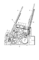
まず、図1乃至図4を参照して電子写真画像形成装置及びプロセスカートリッジの全体構成を説明する。尚、図1はプロセスカートリッジを装着した電子写真画像形成装置の全体構成を示す説明図である。図2及び図3はプロセスカートリッジの構成説明図である。図4は開閉カバーを開いてプロセスカートリッジを装置本体へ装着する状態を説明するための説明図である。
【0013】
この電子写真画像形成装置Aは、図1に示すように、電子写真画像形成プロセスによって記録媒体に画像を形成するものである。そして、像担持体であるドラム形状の電子写真感光体(以下、感光体ドラムと称す)にトナー像を形成する。そして前記トナー像の形成と同期して、給送トレイ3aにセットした記録媒体2をピックアップローラ3b及び搬送ローラ3c等からなる搬送手段3で搬送する。次いで、プロセスカートリッジBの有する前記感光体ドラムに形成したトナー像を転写手段としての転写ローラ4に電圧を印加することによって記録媒体2に転写する。その後トナー像の転写を受けた記録媒体2をガイド3dで定着手段5へと搬送する。この定着手段5は駆動ローラ5a及びヒータを内蔵する定着ローラ5bからなり、通過する記録媒体2に熱及び圧力を印加して転写されたトナー像を定着する。そしてこの記録媒体2を排出ローラ3e、3fで反転搬送して排出トレイ6へと排出する。
【0014】
一方、前記プロセスカートリッジBは、図1、図2に示すように、像担持体としての感光層を有する感光体ドラム7を回転し、その表面を帯電部材としての帯電ローラ8への電圧印加によって一様に帯電する。次いで、光学系1からの画像情報に応じたレーザービーム光を露光開口部9を介して感光体ドラム7へ照射して潜像を形成する。そしてこの潜像をトナーを用いて現像手段10によって現像する。すなわち、現像部材としての帯電ローラ8は感光体ドラム7に接触して設けられてあり、感光体ドラム7に帯電を行う。また、現像手段10は、感光体ドラム7の現像領域へトナーを供給して、感光体ドラム7に形成された潜像を現像する。尚、光学系1は、レーザーダイオード1a、ポリゴンミラー1b、レンズ1c、反射ミラー1dを有している。
【0015】
この現像手段10は、トナー収納部としてのトナー室10a内のトナーを現像室10bへ供給し、現像室10bに取り付けた現像ローラ10cを回転させると共に、現像ブレード10dによって摩擦帯電電荷を付与したトナー層を固定磁石を内蔵した現像ローラ10cの表面に形成し、そのトナーを感光体ドラム7の現像領域へ供給する。そして、そのトナーを前記潜像に応じて感光体ドラム7へ転移させることによって、トナー像を形成して可視像化する。
【0016】
そして転写ローラ4に前記トナー像と逆極性の電圧を印加して、感光体ドラム7に形成されたトナー像を記録媒体2に転写した後に、クリーニング手段11によって感光体ドラム7上の残留トナーを除去する。ここでクリーニング手段11は、弾性クリーニングブレード11aによって感光体ドラム7に残留したトナーを掻き落として廃トナー溜め11bへ集める。
【0017】
前記感光体ドラム7等の各部品は、トナー現像枠体12とトナー現像壁部材13、更にはクリーニング枠体14とを結合して構成するカートリッジ枠体内に収納され、カートリッジ化されている。即ち、トナー現像枠体12とトナー現像壁部材13を溶着してトナー室10a及び現像室10bを構成し、この現像室10bに現像ローラ10c及び現像ブレード10dを取り付けている。またクリーニング枠体14には感光体ドラム7、帯電ローラ8、及びクリーニング手段11を構成する各部材を取り付けている。そして前記トナー現像枠体12とクリーニング枠体14とを揺動可能に結合することによってプロセスカートリッジBを構成する。
【0018】
このプロセスカートリッジBには画像情報に応じた光を感光体ドラム7へ照射するための露光開口部9及び感光体ドラム7を記録媒体2に対向するための転写開口部15が設けてある。そして両開口部9、15を開閉可能なシャッタ部材16が取り付けてある。すなわち、前記転写開口部15は、感光体ドラム7に形成されたトナー像を記録媒体2に転写するためのものである。
【0019】
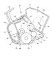
そして画像形成装置Aは、図4に示すように、装置本体17に対して開閉カバー18が軸19を中心にして回動可能に取り付けてある。そして、前記開閉カバー18を開けると装置本体17の内部にはプロセスカートリッジBをガイドするためのガイド部材(レール溝、不図示)が設けてある。そこで、操作者が該ガイド部材に沿ってプロセスカートリッジBを着脱する。このとき図3に示すようにプロセスカートリッジBの長手方向の端壁に設けた第1突起24、第2突起25が前述の装置本体17のガイド部材(不図示)に沿って案内される。
【0020】
図2、図3に示すようにシャッタ部材16は回転自在に支持された回転支軸16cに夫々固定された第1シャッタ部16a、アーム部16dで支持された第2シャッタ部16bを有し、回転支軸16cに装着したねじりコイルばね23のばね力で第1シャッタ部16aが露光開口部9を閉じ、第2シャッタ部16bが転写開口部15を閉じるように付勢され、プロセスカートリッジBが装置本体17外にあるときは、第1シャッタ部16a、第2シャッタ部16bは夫々露光開口部9、転写開口部15を閉じている。
【0021】
クリーニング枠体14に一体的に設けた把手部26を持ってプロセスカートリッジBを装置本体17へ装着する際、感光体ドラム7を覆う第2シャッタ部16bを支持するアーム部16dの先端部の長手方向外方へ突出する係止突起16eが装置本体17に当り、カートリッジ装着部へのそれ以上の進入をとめられた状態でプロセスカートリッジBは第1、第2突起24、25が装置本体17の不図示のガイド部材に沿って前進し、シャッタ部材16は図3に示すように露光開口部9、転写開口部15を開放する位置に来る。プロセスカートリッジBを装置本体17から取り外すと、ねじりコイルばね23のばね力でシャッタ部材16は露光開口部9、転写開口部15を閉じる。
【0022】
(現像手段の構成)
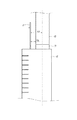
次に図5乃至図10を参照して現像手段の構成ついて説明する。尚、図5は現像手段の断面説明図であり、図6はトナー現像枠体及びトナー現像壁部材を分離した説明図、図7はトナー現像枠体とトナー現像壁部材を結合する組み立て説明図、図8はトナー現像枠体とトナーシール部材の結合を説明する図、図9は現像ローラの支持構成を説明する図、図10はトナー現像枠体とトナーシール端部に設ける端部部材を結合する組立説明図である。
【0023】
現像手段10は、図5及び図6に示すように、トナー現像枠体12とトナー現像壁部材13とを結合してトナー室10a及び現像室10bを構成している。
【0024】
また、トナー現像枠体12には、トナー室10aに収納されているトナーが現像ローラ10cに供給される際に通過するトナー通過開口12a1が設けられている。
【0025】
トナー現像枠体12は、前記トナー室10a及び現像室10bを構成する本体となるものであり、トナー通過開口12a1を有するシール取付部12aを境界として上方にトナー室10aを形成するトナー室部12bを有し、シール取付部12aの下方に現像室10bを形成する現像室部12cを有する。そして、前記トナー室部12b及び現像室部12cの同一面壁部12a3、12c1を開放して構成している。尚、前記トナー室部12b部分は開放側が幅広なるように形成してあり、且つ長手方向における一端部には、トナー室10aにトナーを充填するためのトナー充填口12gが設けられてある。
【0026】
一方、トナー現像壁部材13は、前記トナー現像枠体12の開放壁部に結合するものであり、前記トナー現像枠体12のトナー室10a部分の開放面に結合するトナー壁部13aと、前記現像室10b部分の開放面に結合する現像壁部13bとを一体的に構成している。そして前記トナー壁部13aと現像壁部13bとの境界において、段差が設けられ外部側から見て現像壁部13bに対してトナー壁部13aが凹むような凹部13a1が形成してある。
【0027】
前記トナー現像枠体12及びトナー現像壁部材13は、共に樹脂の射出成型によって形成する。
【0028】
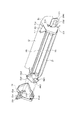
これらを組み立てるには前記トナー現像枠体12の開放壁部分にトナー現像壁部材13を接合すると共に、該接合部分を溶着して結合する。尚、本実施の形態では前記トナー現像枠体12とトナー現像壁部材13とを結合するときに、図7に示すように、両部材12、13の長手方両端に端部部材21を取り付け、両者を正確に位置決めするようにしている。
【0029】
そのため、トナー現像枠体12の長手方向両端側面には位置決め用のボス穴12b1、12b2が設けてあり、同様にトナー現像壁部材13の長手方向両端側面にも位置決め用のボス13cが設けてある。そして端部部材21には前記ボス穴12b1、12b2、とボス13cに嵌入し得る位置決め手段としてのボス21a1とボス穴21a2が設けてある。
【0030】
従って、前記トナー現像枠体12とトナー現像壁部材13とを接合し、該接合部のうちトナー壁部13aの部分は溶着し、現像壁部13b部分には発泡ポリウレタンで構成したトナー漏れ防止シール22(図5参照)を介在させて圧接することにより両者を結合する。このときシール22を介在させた接合部分は溶着されていないために、溶着した場合のように強固な接合状態ではない。しかしながら、前記端部部材21のボス21a1をそれぞれのボス穴12b1、12b2に嵌入し、且つ、端部部材21のボス穴21a2にトナー現像壁部材13のボス13cを取り付けることにより、トナー現像枠体12とトナー現像壁部材13とが位置決めされる。そして、前記接合部に捻れ等の力が加わったとしても前記接合部に隙間が生ずることはなく、該部分からトナーが漏れるおそれがなくなる。
【0031】
端部部材21にはクリーニング枠体14へ向ってアーム部21eが突出しており、アーム部21eの先端に設けた長手方向の結合穴21fとクリーニング枠体14に設けた不図示の結合穴に嵌入する不図示のピンによりクリーニング枠体14と端部部材21は回動可能に結合される。そしてアーム部21eの上のばね止め21gに内径が嵌入する圧縮コイルばね(不図示)のクリーニング枠体14との間に縮設され、現像ローラ10c両側の隙間保持部材50と感光体ドラム7が圧接する。
【0032】
また前記のようにしてトナー現像枠体12と壁部材13とを結合したとき、壁部材13に凹部13a1が形成してあるために、トナー壁部13aの下端が前記トナー通過開口12a1の縁部と略一致するようになる(図5参照)。なお、前記トナー通過開口12a1に封止部材としてのシール部材27を接着或は溶着等することによって前記開口12a1を開封可能に封止している。
【0033】
前記のように一体化されたトナー現像枠体12及び壁部材13に、感光体ドラム7やクリーニング手段11等を組み付けたクリーニング枠体14を結合することによってプロセスカートリッジBを組み立てる。
【0034】
このとき、図5に示すように、トナー室10aは現像室10bの上方へ位置し、且つトナー室10aの一部が現像室10bよりも感光体ドラム7側へ突出するようにトナー現像枠体12の形状を構成している。
【0035】
また、トナー現像枠体12には、トナー現像壁部材13の有する現像手段取り付け部13dに取り付ける現像ローラ10cの周面に付着するトナーの量を規制する現像ブレード10dを取り付けるための現像ブレード取り付け部10d1が設けられている。そしてトナー現像枠体12の有するトナー収納部を構成する壁部10a1が、前記トナー通過開口12a1方向へ向って傾斜している。そこでトナー収納部内のトナーを無駄なく現像領域へ供給できる。尚、前記トナー通過開口12a1には、トナー通過開口12a1を開封可能に封止するシール部材27が取り付けられる。このシール部材27によって、トナー収納部内のトナーが、プロセスカートリッジ使用前に漏れることはない。尚、このシール部材27は、プロセスカートリッジを使用するに先立って、操作者によって取り外される。
【0036】
更にトナー現像壁部材13の有する前記蓋部材(トナー壁部13a)は、トナー現像枠体12とトナー現像壁部材13とを結合した際に、前記トナー通過開口12a1へ向って傾斜している傾斜面13a2を有する。尚この傾斜面13a2の下方端部13a3と前記トナー通過開口12a1の下側縁部とがほぼ一致する。そこで、トナー収納部内のトナーを無駄なく現像領域へ供給できる。
【0037】
ここで、トナー現像枠体12とトナー現像壁部材13とは結合する際に、前記トナー収納部の設けられている側の端部12f,13fを結合される。この結合は、例えば溶着(例えば超音波溶着)、接着、ねじ止め、或いはクリップ、スプリング等によって行われる。更にトナー現像枠体12とトナー現像壁部材13とを結合するために、トナー現像枠体12とトナー現像壁部材13の長手方向両端部に結合する端部部材21が設けられている。ここでトナー現像枠体12とトナー現像壁部材13には、その長手方向端部に位置決め部としてのボス21aが設けられている。そこで、トナー現像枠体12とトナー現像壁部材13を結合する際に、前記ボス21aが前記端部材21に設けられた位置決め部としての穴と係合して、両枠体の位置決めが行われる。また更に、トナー現像枠体12とトナー現像壁部材13は結合する際に、前記現像手段取り付け部13dの設けられている側は弾性シール部材(トナー漏れ防止シール22)を介在させた状態で結合される。
【0038】
尚、このトナー現像枠体12とトナー現像壁部材13は、ともにプラスチック製(例えば、ハイインパクトスチロール)で、各々一体成形されている。
【0039】
これにより、プロセスカートリッジBを大型化することなくトナー室10aの容量が大きくなり、多くのトナーを収納することが可能となる。そして前記のようにトナー室10aの容量を大きくしても、トナー現像枠体12のトナー室10a部分は開放側が幅広になるように形成してあるために、樹脂等の射出成形によってトナー現像枠体12を形成することができる。
【0040】
また前記トナー室10aのトナーは、使用開始時にシール部材27を剥離するとトナー室10aから下方にある現像室10bへトナー搬送部材90によって供給される。更に、画像形成装置Aに装着した状態(図5の状態)でシール取付部12aが右下方へ傾斜している。しかしながら、トナー通過開口12a1の下側縁部にはトナー現像壁部材13に設けた凹部13a1によってトナー壁部13aが位置しているために、シール取付部12aの裏側にトナーが残留することはない。
【0041】
ここで前記トナー現像枠体12とトナー現像壁部材13との結合は、前記のように溶着によるのが接合部が確実に密着してトナー漏れ等を防止する上で好ましいが、溶着以外であっても例えば前記接合部分に発泡ポリウレタン等のシールを介在させることにより、ねじ止めや掛り止め、或いは接着等によって結合してもよい。
【0042】
また、前記現像手段10の前記トナー室10aには、図2に示すように、トナーを攪拌、搬送するトナー搬送部材90が回転自在に設けられ、トナー室10aから現像室10bにトナーを搬送する。また、トナー搬送部材90の一端部は、図19に示すように、搬送ギヤ76に接続している。したがって、前記感光ドラム7の端部に固定されたドラムギア(不図示)から、このドラムギアと噛み合っている、現像ローラ10cの端部に固定された現像ローラギア、アイドラギア(不図示)を伝って、搬送ギア76に駆動力が伝達され、前記トナー搬送部材90が駆動される。
【0043】
(端部部材と把手部材の構成)
端部部材21の一方は感光ドラム7の端部に固定したドラムギア(不図示)に噛み合っている、現像ローラ10cの端部に固定した現像ローラギア73(図21参照)と、前記現像ローラギア73から前記搬送部材90の搬送ギア76に駆動を伝達する為のアイドラギア74、75からなるギアトレイン(不図示)を覆う。また、他方の端部部材21には以下に述べる把手部材21bが設けられている。
【0044】
次に、把手部材とトナーシール部材構成について詳細に説明する。図11は端部部材の組立説明図、図12、13、14は把手部材の詳細説明図である。
【0045】
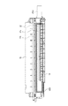
図8に示すように、トナー現像枠体12のトナー通過開口12a1を塞ぐように、長手方向に裂けやすいカバーフィルム27bがシール取付部12aに貼付けられている(図5参照)。このカバーフィルム27bは、前記トナー通過開口12a1の4辺の縁に沿ってシール取付部12aに貼付けられている。このカバーフィルム27bにはトナー通過開口12a1を開封するために、カバーフィルム27bを引き裂く為のテアテープ27aが溶着されている。そして、このテアテープ27aは、トナー通過開口12a1の長手方向一端のシール取付部端12a2で折り返されて、トナー現像枠体12の穴12d(図10参照)を通って外部へひきだされる。テアテープ27aの外部の引き出された端部27a1は更に端部部材21の穴21hを挿通して外部へ引き出されて手掛けとなる板状の把手部材21bに取付けてある。前記把手部材21bは端部部材21から取り外し可能に設けられている。詳しくは、前記端部部材21と接続する接続部21cの肉厚を特に薄くし折曲して切り離せるようにしてある。また、把手部材21bと端部部材21とは一体成形されている。このように一体成形することにより、把手部材21bと端部部材21とを別部品とする場合に比べ、コストダウンをすることができる。なお、好ましくは、ハイインパクトポリスチレンを用いて、一体成形するのがよい。そして、テアテープ27aの端部をこの把手部材21bに両面テープ21b1等で接着または溶着している。
【0046】
トナー現像枠体12に収納されたトナーTは、プロセスカートリッジBの外部へ突出しているテアテープ27aの端部27a1と把手部材21の根本側を端部部材21から切り離し、引きちぎった後に把手部材21bの突状21kを操作者が指に引っかけ、ひくことにより、テアテープ27aが引き出されてカバーフィルム27bが引き裂かれて、トナー現像枠体12のトナー通過開口12a1が開封され、トナー室10aから現像室10bへ送出し可能となる。また、図13に示すように、前記把手部材21bにはプロセスカートリッジの識別のための表示部21dを有する。表示部21dに文字や色付けなどをすることにより、使用者が適正な製品であるかどうかの確認が容易になる。また図13、14に示すように把手部材21bに短手方向の突起である突状21kを設けると、把手部材21bを端部部材21から引きちぎるのに力を加え易いし、テアテープ27aを引く際、突状21kに指を掛けられるので操作性がよい。
【0047】
次に端部部材21の構成についてさらに詳しく説明する。
【0048】
端部部材21のトナー現像枠体12に組み付けられる側には、現像ローラ10cを位置決めするためのボス21a1が設けられている。具体的には、現像ローラ10cの両端部の軸10eを軸受け部材10c1の受け穴10c2に嵌合させた状態で、軸受け部材10c1の位置決め穴10c3の2箇所に前記ボス21a1を挿通させる。さらにこのボス21a1を前記トナー現像枠体12の位置決め穴12b1,12b2に嵌入することにより、現像ローラ10cを位置決めする。
【0049】
また、端部部材21の前記ボス21a1が設けられている側には、トナー現像枠体12とトナー現像壁部材13とを位置決めするためのボス穴21a1が設けられている。このボス穴21a1にトナー現像壁部材13のボス13cを嵌入することにより、トナー現像枠体12とトナー現像壁部材13とを位置決めする。
【0050】
また端部部材21には、クリーニング枠体14に向かってアーム部21eが突出して設けられている。このアーム部21eの先端部には結合穴21fが設けられている。そして、この結合穴21fとクリーニング枠体14に設けられた結合穴(不図示)にピン(不図示)を嵌入することにより、クリーニング枠体14と端部部材21は回動可能に結合される。
【0051】
また、アーム部21eには、バネ止め21gが突出して設けられている。このバネ止め21gに圧縮バネ(不図示)を圧入し、この圧縮バネをクリーニング枠体14に圧接することにより、前記現像ローラ10cの両端部に設けられた隙間保持部材50を感光体ドラム7に圧接する。
【0052】
また、前述した二つのボス21a1の間には、端部部材21をトナー現像枠体12にねじ止めするためのねじ穴21mが設けられている。
【0053】
次に、把手部材21bが端部部材21と接続する接続部21cの構成についてさらに詳しく説明する。
【0054】
この接続部21cは、把手部材21bが端部部材21から分離される部分の中央部に設けられた第1溝21c1、及び、一端部と他端部に設けられた第2溝21c2を有する。そして、第1溝21c1は、第2溝21c2よりも幅が広く、また、底が深い。把手部材21bを端部部材21から分離する際には、まず、把手部材21bを、図14に示すP方向へ曲げる。これにより、図15に示すように第2溝21c2の底部に第1裂け目面21c3と第2裂け目面21c4とが生じる。次に、把手部材21bを図15に示すQ方向へ曲げる。これにより、第1裂け目面21c3と第2裂け目面21c4とが当接し、接続部21cの一端部と他端部の、第1溝21c1及び第2溝21c2の形成された面とは反対側の面に裂け目が生じる。さらに、把手部材21bをQ方向へ曲げると、この裂け目は中央部に向かって進向し、最終的に把手部材21bは、端部部材21から分離される。
【0055】
次に端部部材21の具体的形状について説明する。図14において、把手部材21bの肉厚L1は、1mm〜4mm、好ましくは、約2.5mmである。また第1溝21c1の深さL2は、1mm〜3mm、好ましくは約2mm、第2溝21c2の深さL3は0.5mm〜2mm、好ましくは約1mmである。また第1溝21c1の幅L4は、1.5mm〜3mm、好ましくは約2.3mmであり、第2溝21c2の幅L5は、1mm〜2mm、好ましくは、約1.3mmである。また把手部材21bの長さL6は、25mm〜30mm、好ましくは約27.3mmであり、幅L7(図13参照)は20mm〜24mm、好ましくは約21.8mmである。また、前述した結合穴21fとねじ穴21mとの中心間の位置関係については、図13において、L8は、26mm〜29mm、好ましくは約27.6mm、L9は、19mm〜23mm、好ましくは、約20.8mmである。また、図13において、ねじ穴21mの中心と、把手部材21bの中心との距離L10は、16mm〜19mm、好ましくは、約17.9mmである。
【0056】
(現像手段の組立方法)
次に図10を参照して、プロセスカートリッジの現像手段10の組立工程について説明する。まず、前記トナー現像枠体12にトナーを搬送、攪拌を行うトナー搬送部材90を取り付ける。前記トナー搬送部材90の一端部は前記トナー現像枠体12に回転自在に取付けられ、他端部は前記搬送ギア76(図19参照)に接続している。次に、トナーシール部材27を前記トナー現像枠体12のシール取付け部12aに貼付ける(図8参照)。前記トナーシール部材27は、トナー通過開口12a1の長手方向の一端のシール取付け部端12a2で折り返され、トナー現像枠体12の穴12dを通って、外部へ引き出される。次に、前記トナー搬送部材90とトナーシール部材27を取り付けた前記トナー現像枠体12に前記トナー現像壁部材13を一体に溶着し固定する。次に、前記トナー現像枠体12の長手方向の一方側面に設けられたトナー充填口12gからトナーを充填する。
【0057】
本実施の形態によれば、このトナー充填作業を容易にすることができる。以下、詳しく説明する。図17及び図19は、切り欠き部64を有する把手部材61がトナー容器60に一体的に成形されている場合である。この場合、把手部材61が不用意に曲がってしまうと、トナー充填装置63により、トナー充填口62からトナーを充填する際に、トナー充填装置63と把手部材61とが干渉するおそれがある。
【0058】
また、人手によりトナー充填口62からトナーを充填する際にも、トナー充填口62の近くに把手部材61があるために、充填作業がしづらい。
【0059】
これらの問題は、トナー容器を小型化する場合、より顕著になる。図18及び図20に示すようにトナー容器を小型化すると、トナー容器70の長手方向の一端部に設けられたトナー充填口72の中心線と把手部71の間隔L2が、狭くなる。また、トナー充填装置73と把手部材71のクリアランスT2も十分に確保できなくなる。したがって、トナーを充填する際に、トナー充填装置73と把手部材71とがより干渉しやすくなる。
【0060】
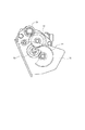
なお、前記小型のトナー容器70の場合、トナー充填口72を把手部材71と反対側(駆動側)に移動することも考えられるが、反対側には、図21に示すように、トナーを搬送するトナー搬送部材(不図示)を駆動する搬送ギア76に現像ローラギア73から駆動力を伝達するギア列(アイドラギア74、75)が配置されている為に、トナー充填口72を配置することは困難である。
【0061】
これに対し、本実施の形態によれば、把手部材21bは、トナー容器にではなく、端部部材に設けられている。したがってトナー充填装置によるか、人手によるかを問わず、トナー収納部へのトナーの充填作業を容易にすることができる。
【0062】
このようにしてトナーを充填した後、トナー充填口12gをキャップ12hで封止する。その後、前記現像ブレード10bを前記トナー現像枠体12の前記現像ブレード取付け部10b1(図2参照)に取付ける。次に、前記現像ローラ10cを前記トナー現像枠体12に位置決めする。この現像ローラ10cの位置決めに際しては、まず、前記現像ローラ10cの両端部に、前記隙間保持部材50を被せる。次に、軸10eの両端を、軸受け部材10c1の受け穴10c2に嵌合する。次に前記軸10eの一端部には現像ローラギアを取付る。その後、軸受け部材10c1の位置決め穴10c3の2箇所に端部部材21のボス21a1を挿通させ、前記トナー現像枠体12の位置決め穴12b1,12b2に嵌入して、取付け固定する。なお、この端部部材21は、トナー充填口12gを覆うようにトナー室10aの長手方向における一端部に設けられる。また、前記端部部材21のボス穴21a2にトナー現像壁部材13のボス13cを嵌入することにより、トナー現像枠体12とトナー現像壁部材13とが位置決めされる。またこの端部部材21を取り付ける際には、トナー現像枠体12の穴12dを通って外部へひきだされたトナーシール部材27の端部27a1を前記端部部材21の穴21hを挿通して外部へひきだされて、端部部材21に一体に成形された把手部材21bに両面テープ21b1で固定される(図11参照)。
【0063】
以上説明したように、本実施の形態に係る端部部材は、電子写真感光体と、前記電子写真感光体に形成された潜像を現像するための現像部材と、前記現像部材の現像に用いる現像剤を収納するための現像剤収納部と、前記現像剤収納部に現像剤を充填するための、前記現像剤収納部の長手方向における一端部に設けられた現像剤充填口と、前記現像剤収納部に収納されている現像剤が前記現像部材に供給される際に通過する現像剤通過開口と、前記現像剤通過開口を開封可能に封止する封止部材とを有するプロセスカートリッジに用いられる端部部材であって、前記封止部材を開封する際に把持するための、前記封止部材の長手方向における一端部と接続する把手部材、を取り外し可能に有して、前記現像剤充填口を覆うように前記現像剤収納部の長手方向における一端部に取り付けられることを特徴とする端部部材である。
【0064】
また、前記把手部材が、前記端部部材から切り離し可能に一体に設けられている。
【0065】
また、前記端部部材及び前記把持部材が、プラスチック製であって一体成形されている。
【0066】
また、前記把持部材が、平板状であって、前記封止部材の長手方向に交差する方向の突起が板面上に一体成形されている。
【0067】
また、前記把手部材の肉厚は、1mm〜4mmである。
【0068】
また、前記把手部材の肉厚は、約2.5mmである。
【0069】
また、前記把手部材が、前記端部部材から切り離される部分の長手方向における中央部に第1溝が設けられ、一端部と他端部に前記第1溝よりも浅い第2溝が設けられている。
【0070】
また、前記第1溝の深さは、1mm〜3mmであり、前記第2溝の深さは、0.5mm〜2mmである。
【0071】
また、前記端部部材は、さらに、前記端部部材を、前記現像剤収納部にねじ止めするためのねじ穴を有しており、前記ねじ穴の深さ方向から見て、前記ねじ穴の中心と、前記把手部材の中心との距離が、16mm〜19mmである。
【0072】
また、前記ねじ穴の中心と、前記把手部材の中心との距離が、約17.9mmである。
【0073】
【発明の効果】
本発明によれば、現像剤充填装置によるか人手によるかを問わず、現像剤収納部への現像剤の充填作業を容易にすることのできる端部部材、及び、プロセスカートリッジを提供することができる。
【図面の簡単な説明】
【図1】プロセスカートリッジを装着した画像形成装置の縦断面図である。
【図2】プロセスカートリッジの縦断面図である。
【図3】プロセスカートリッジの斜視図である。
【図4】画像形成装置の開閉カバーを開いてプロセスカートリッジを装着する状態を示す縦断面図である。
【図5】プロセスカートリッジの縦断面図である。
【図6】トナー現像枠体及びトナー現像壁部材を分離した斜視図である。
【図7】トナー現像枠体とトナー現像壁部材を結合する組み立てを説明する斜視図である。
【図8】トナー現像枠体とトナーシール部材の結合を説明する正面図である。
【図9】現像ローラの支持構成を説明する図
【図10】トナー現像枠体と端部部材との組み立てを説明する斜視図である。
【図11】端部部材の組立説明図。
【図12】端部部材の斜視図。
【図13】端部部材の側面図である。
【図14】図10のA−A断面図である。
【図15】把手部材の分離手順を説明する図。
【図16】把手部材の分離手順を説明する図。
【図17】トナー充填口と把手部のクリアランス説明図。
【図18】トナー充填口と把手部のクリアランス説明図。
【図19】トナー充填口と把手部のクリアランス説明図。
【図20】トナー充填口と把手部のクリアランス説明図。
【図21】プロセスカートリッジの駆動側を説明する図。
【符号の説明】
A 画像形成装置
B プロセスカートリッジ
T トナー
1 光学系
1a レーザーダイオード
1b ポリゴンミラー
1c レンズ
1d 反射ミラー
2 記録媒体
3a 給送トレイ
3b ピックアップローラ
3c 搬送ローラ
3d ガイド
3e,3f 排出ローラ
4 転写ローラ
5 定着手段
5a 駆動ローラ
5b 定着ローラ
6 排出トレイ
7 感光体ドラム
8 帯電ローラ
9 露光開口部
10 現像手段
10a トナー室
10a1 壁部
10b 現像室
10c 現像ローラ
10d 現像ブレード
10d1 現像ブレード取り付け部
11 クリーニング手段
11a クリーニングブレード
11b 廃トナー溜め
10c1 軸受け部材
10c2 受け孔
10c3 位置決め穴
12 トナー現像枠体
12a シール取付部
12a1 トナー供給開口
12a2 シール取付端部
12a3 壁部
12b トナー室部
12b1,12b2 ボス穴
12b3 開放部分
12c 現像室部
12c1 壁部
12d 穴
12f 端部
12g トナー充填口
12h キャップ
13 トナー現像壁部材
13a トナー壁部
13a1 凹部
13a2 傾斜面
13a3 下方端部
13b 現像壁部
13c ボス
13d 現像手段取り付け部
13f 端部
14 クリーニング枠体
15 転写開口部
16 シャッタ部材
16a 第1シャッタ部
16b 第2シャッタ部
16c 回動支軸
16d アーム部
16e 係止突起
17 装置本体
18 開閉カバー
19 回動軸
21 端部部材
21a1 ボス
21a2 穴
21b 把手部材
21b1 両面テープ
21c 接続部
21d 表示部
21e アーム部
21f 結合穴
21g ばね止め
21h 穴
21i 凸部
21k 突状
22 トナー漏れ防止シール
23 捩じりコイルバネ
24 第1突起
25 第2突起
26 把手部材
27 シール部材
27a テアテープ
27a1 テアテープ端部
70,60 トナー容器
71,61 把手部
72,62 充填口
73 現像ローラギア
74,75 アイドラギア
76 搬送ギア[0001]
BACKGROUND OF THE INVENTION
The present invention is used in an electrophotographic image forming apparatus.Process cartridgeIt is about.
[0002]
[Prior art]
Conventionally, in an electrophotographic image forming apparatus using an electrophotographic image forming process, the electrophotographic photosensitive member and the process means acting on the electrophotographic photosensitive member are integrally formed into a cartridge, and the cartridge can be attached to and detached from the apparatus main body. The process cartridge method is adopted. According to this process cartridge system, the apparatus can be maintained by the user himself / herself without depending on the service person, so that the operability can be remarkably improved. Therefore, this process cartridge system is widely used in electrophotographic image forming apparatuses.
[0003]
In such a process cartridge, a toner frame having a toner chamber containing a developer (toner) and a developing frame containing a developing member are integrally provided, and between the toner frame and the developing frame. In addition, a toner seal member is provided for sealing the toner until the use of the process cartridge is started. The both frames are combined with a drum frame that supports the electrophotographic photosensitive member.
[0004]
Here, the toner seal member may be fixed to a handle member formed integrally with the toner frame by a fixing means such as a double-sided tape. A part of the handle member molded integrally with the toner frame has a notch so that the user can easily bend and cut it. The user bends and cuts the notch portion of the handle member, and pulls out the handle member to open the toner seal member.
[0005]
[Problems to be solved by the invention]
The present invention is a development of the above-described prior art.
[0006]
An object of the present invention is to provide an end member and a process cartridge capable of facilitating the filling operation of the developer into the developer storage section regardless of whether the developer filling apparatus or the manual operation is performed.
[0007]
[Means for Solving the Problems]
The main present invention isA process cartridge that can be attached to and detached from the electrophotographic image forming apparatus main body,
An electrophotographic photoreceptor;
A developing member for developing the electrostatic latent image formed on the electrophotographic photosensitive member;
A developer accommodating portion for accommodating a developer used for developing the developing member;
A developer filling port provided at one end in the longitudinal direction of the developer accommodating portion for filling the developer accommodating portion with the developer;
A developer passage opening through which the developer accommodated in the developer accommodating portion passes when supplied to the developing member;
A sealing member that seals the developer passage opening in an openable manner;
A detachable handle member connected to one end portion of the sealing member in the longitudinal direction for gripping when the sealing member is opened, and a seal member for opening the developer passage opening. An end member attached to the one end portion of the developer accommodating portion so as to cover the developer filling port, and a hole portion for pulling out the one end portion to the outside;
Process cartridge characterized by havingIt is.
[0008]
Another main invention of the present application is a process cartridge that is attachable to and detachable from an electrophotographic image forming apparatus main body, an electrophotographic photosensitive member, and a developing member for developing a latent image formed on the electrophotographic photosensitive member. A developer accommodating portion for accommodating a developer used for developing the developing member; and a longitudinal end of the developer accommodating portion for filling the developer accommodating portion with the developer. A developer filling port, a developer passage opening through which the developer housed in the developer housing portion is supplied to the developing member, and a seal that seals the developer passage opening so as to be openable. A member and a grip member connected to one end portion in the longitudinal direction of the sealing member for gripping when the sealing member is opened are detachable, and so as to cover the developer filling port Longitudinal direction of developer storage A process cartridge and having a an end portion member attached to one end definitive.
[0009]
DETAILED DESCRIPTION OF THE INVENTION
First,
[0010]
[Embodiment 1]
Here, the description of the first embodiment will be made in the order of (1) the overall configuration of the image forming apparatus and the process cartridge, (2) the frame configuration of the developing means, and (3) the configuration of the end member and the handle member.
[0011]
In the following description, the longitudinal direction refers to a direction perpendicular to the direction in which the process cartridge is inserted into the apparatus main body and parallel to the surface of the recording medium. A direction perpendicular to the longitudinal direction is referred to as a short direction.
[0012]
(overall structure)
First, the overall configuration of the electrophotographic image forming apparatus and the process cartridge will be described with reference to FIGS. FIG. 1 is an explanatory diagram showing the overall configuration of an electrophotographic image forming apparatus equipped with a process cartridge. 2 and 3 are explanatory diagrams of the structure of the process cartridge. FIG. 4 is an explanatory view for explaining a state in which the opening / closing cover is opened and the process cartridge is attached to the apparatus main body.
[0013]
This electrophotographic image forming apparatus A forms an image on a recording medium by an electrophotographic image forming process as shown in FIG. Then, a toner image is formed on a drum-shaped electrophotographic photosensitive member (hereinafter referred to as a photosensitive drum) which is an image carrier. In synchronism with the formation of the toner image, the
[0014]
On the other hand, as shown in FIGS. 1 and 2, the process cartridge B rotates a
[0015]
The developing means 10 supplies toner in a
[0016]
Then, a voltage having a polarity opposite to that of the toner image is applied to the transfer roller 4 to transfer the toner image formed on the
[0017]
Each component such as the
[0018]
The process cartridge B is provided with an exposure opening 9 for irradiating the
[0019]
In the image forming apparatus A, as shown in FIG. 4, an opening /
[0020]
As shown in FIGS. 2 and 3, the
[0021]
When the process cartridge B is mounted on the apparatus
[0022]
(Configuration of developing means)
Next, the configuration of the developing means will be described with reference to FIGS. 5 is a cross-sectional explanatory view of the developing means, FIG. 6 is an explanatory view in which the toner developing frame and the toner developing wall member are separated, and FIG. 7 is an explanatory view of assembly in which the toner developing frame and the toner developing wall member are coupled. 8 is a diagram for explaining the coupling between the toner developing frame and the toner seal member, FIG. 9 is a diagram for explaining the support structure of the developing roller, and FIG. It is assembly explanatory drawing to couple | bond.
[0023]
As shown in FIGS. 5 and 6, the developing
[0024]
Further, the
[0025]
The
[0026]
On the other hand, the toner developing
[0027]
The
[0028]
To assemble these, the toner developing
[0029]
Therefore, positioning boss holes 12b1 and 12b2 are provided on both side surfaces in the longitudinal direction of the
[0030]
Therefore, the
[0031]
An
[0032]
Further, when the
[0033]
The process cartridge B is assembled by coupling the
[0034]
At this time, as shown in FIG. 5, the
[0035]
Further, a developing blade attachment portion for attaching a developing
[0036]
Further, the lid member (
[0037]
Here, when the
[0038]
The
[0039]
Thereby, the capacity of the
[0040]
The toner in the
[0041]
Here, the connection between the toner developing
[0042]
Further, as shown in FIG. 2, the
[0043]
(Configuration of end member and handle member)
One
[0044]
Next, the structure of the handle member and the toner seal member will be described in detail. FIG. 11 is an assembly explanatory view of the end member, and FIGS. 12, 13, and 14 are detailed explanatory views of the handle member.
[0045]
As shown in FIG. 8, a
[0046]
The toner T stored in the
[0047]
Next, the configuration of the
[0048]
A boss 21a1 for positioning the developing
[0049]
A boss hole 21a1 for positioning the
[0050]
The
[0051]
The
[0052]
Further, a
[0053]
Next, the configuration of the connecting
[0054]
This
[0055]
Next, a specific shape of the
[0056]
(Assembling method of developing means)
Next, the assembly process of the developing means 10 of the process cartridge will be described with reference to FIG. First, a
[0057]
According to the present embodiment, this toner filling operation can be facilitated. This will be described in detail below. 17 and 19 show a case where the
[0058]
Further, when the toner is manually filled from the
[0059]
These problems become more prominent when the toner container is downsized. As shown in FIGS. 18 and 20, when the toner container is reduced in size, the distance L2 between the center line of the
[0060]
In the case of the
[0061]
In contrast, according to the present embodiment, the
[0062]
After the toner is thus filled, the
[0063]
As described above, the end member according to the present embodiment is used for developing an electrophotographic photosensitive member, a developing member for developing a latent image formed on the electrophotographic photosensitive member, and developing the developing member. A developer accommodating portion for accommodating the developer; a developer filling port provided at one end in the longitudinal direction of the developer accommodating portion for filling the developer accommodating portion with the developer; Used in a process cartridge having a developer passage opening through which developer housed in the developer housing portion is supplied to the developing member and a sealing member that seals the developer passage opening so that the developer passage opening can be opened. An end member that is removably connected to one end in the longitudinal direction of the sealing member for grasping when the sealing member is opened, and is filled with the developer The developer collection so as to cover the mouth. It is an end member, characterized in that attached to one end portion in the longitudinal direction of the parts.
[0064]
Moreover, the said handle member is integrally provided so that isolation | separation from the said edge part member is possible.
[0065]
Further, the end member and the gripping member are made of plastic and integrally formed.
[0066]
Moreover, the said holding member is flat form, Comprising: The protrusion of the direction which cross | intersects the longitudinal direction of the said sealing member is integrally molded on the plate surface.
[0067]
The thickness of the handle member is 1 mm to 4 mm.
[0068]
The handle member has a thickness of about 2.5 mm.
[0069]
Further, the handle member is provided with a first groove at a central portion in a longitudinal direction of a portion separated from the end member, and provided with a second groove shallower than the first groove at one end and the other end. Yes.
[0070]
The depth of the first groove is 1 mm to 3 mm, and the depth of the second groove is 0.5 mm to 2 mm.
[0071]
Further, the end member further has a screw hole for screwing the end member to the developer accommodating portion, and when viewed from the depth direction of the screw hole, The distance between the center and the center of the handle member is 16 mm to 19 mm.
[0072]
The distance between the center of the screw hole and the center of the handle member is about 17.9 mm.
[0073]
【The invention's effect】
According to the present invention, it is possible to provide an end member and a process cartridge capable of facilitating the filling operation of the developer into the developer accommodating portion regardless of whether the developer filling device or the manual operation is performed. it can.
[Brief description of the drawings]
FIG. 1 is a longitudinal sectional view of an image forming apparatus equipped with a process cartridge.
FIG. 2 is a longitudinal sectional view of a process cartridge.
FIG. 3 is a perspective view of a process cartridge.
FIG. 4 is a longitudinal sectional view illustrating a state where a process cartridge is mounted by opening an opening / closing cover of the image forming apparatus.
FIG. 5 is a longitudinal sectional view of a process cartridge.
FIG. 6 is a perspective view in which a toner developing frame and a toner developing wall member are separated.
FIG. 7 is a perspective view illustrating an assembly for coupling a toner developing frame and a toner developing wall member.
FIG. 8 is a front view illustrating the coupling between the toner developing frame and the toner seal member.
FIG. 9 is a view for explaining a support structure of a developing roller.
FIG. 10 is a perspective view illustrating assembly of a toner developing frame and an end member.
FIG. 11 is an assembly explanatory view of an end member.
FIG. 12 is a perspective view of an end member.
FIG. 13 is a side view of the end member.
14 is a cross-sectional view taken along the line AA in FIG.
FIG. 15 is a diagram illustrating a procedure for separating a handle member.
FIG. 16 is a diagram illustrating a procedure for separating a handle member.
FIG. 17 is an explanatory view of the clearance between the toner filling port and the handle.
FIG. 18 is an explanatory diagram of the clearance between the toner filling port and the handle.
FIG. 19 is an explanatory view of the clearance between the toner filling port and the handle.
FIG. 20 is a diagram for explaining the clearance between the toner filling port and the handle.
FIG. 21 is a diagram illustrating a drive side of a process cartridge.
[Explanation of symbols]
A Image forming apparatus
B Process cartridge
T Toner
1 Optical system
1a Laser diode
1b Polygon mirror
1c lens
1d reflection mirror
2 recording media
3a Feeding tray
3b Pickup roller
3c Conveyance roller
3d guide
3e, 3f Discharge roller
4 Transfer roller
5 Fixing means
5a Drive roller
5b Fixing roller
6 Discharge tray
7 Photosensitive drum
8 Charging roller
9 Exposure aperture
10 Development means
10a Toner chamber
10a1 wall
10b Development chamber
10c Development roller
10d Development blade
10d1 Development blade attachment
11 Cleaning means
11a Cleaning blade
11b Waste toner reservoir
10c1 Bearing member
10c2 receiving hole
10c3 Positioning hole
12 Toner development frame
12a Seal mounting part
12a1 Toner supply opening
12a2 Seal mounting end
12a3 wall
12b Toner chamber
12b1, 12b2 Boss hole
12b3 open part
12c Development chamber
12c1 wall
12d hole
12f end
12g Toner filling port
12h cap
13 Toner developing wall member
13a Toner wall
13a1 recess
13a2 inclined surface
13a3 Lower end
13b Development wall
13c boss
13d Developing means mounting part
13f end
14 Cleaning frame
15 Transfer opening
16 Shutter member
16a 1st shutter part
16b 2nd shutter part
16c Rotating spindle
16d arm part
16e Locking protrusion
17 Device body
18 Opening and closing cover
19 Rotating shaft
21 End member
21a1 boss
21a2 hole
21b Handle member
21b1 double-sided tape
21c connection part
21d Display section
21e Arm part
21f Connecting hole
21g Spring stopper
21h hole
21i Convex
21k protrusion
22 Toner leakage prevention seal
23 Torsion coil spring
24 First protrusion
25 Second protrusion
26 Handle member
27 Seal member
27a tear tape
27a1 Tear tape end
70, 60 toner container
71, 61 Handle part
72,62 filling port
73 Developing roller gear
74,75 idler gear
76 Conveyor gear
Claims (7)
電子写真感光体と、
前記電子写真感光体に形成された静電潜像を現像するための現像部材と、
前記現像部材の現像に用いる現像剤を収納するための現像剤収納部と、
前記現像剤収納部に現像剤を充填するための、前記現像剤収納部の長手方向の一端部に設けられた現像剤充填口と、
前記現像剤収納部に収納されている現像剤が前記現像部材に供給される際に通過する現像剤通過開口と、
前記現像剤通過開口を開封可能に封止する封止部材と、
前記封止部材を開封する際に把持するための、前記封止部材の長手方向の一端部と接続する、取り外し可能な把手部材と、前記現像剤通過開口を開封するために前記封止部材の前記一端部を外部に引き出すための穴部と、を有して、前記現像剤充填口を覆うように前記現像剤収納部の前記一端部に取り付けられている端部部材と、
を有することを特徴とするプロセスカートリッジ。A process cartridge that can be attached to and detached from the electrophotographic image forming apparatus main body,
An electrophotographic photoreceptor;
A developing member for developing the electrostatic latent image formed on the electrophotographic photosensitive member;
A developer accommodating portion for accommodating a developer used for developing the developing member;
A developer filling port provided at one end in the longitudinal direction of the developer accommodating portion for filling the developer accommodating portion with the developer;
A developer passage opening through which the developer accommodated in the developer accommodating portion passes when supplied to the developing member;
A sealing member that seals the developer passage opening in an openable manner;
A detachable handle member connected to one end portion of the sealing member in the longitudinal direction for gripping when the sealing member is opened, and a seal member for opening the developer passage opening. a, a hole for pulling out one end portion to the outside, and an end member to which the is the attached to the one end of the developer accommodating portion so as to cover the developer filling opening,
A process cartridge comprising:
Priority Applications (2)
| Application Number | Priority Date | Filing Date | Title |
|---|---|---|---|
| JP11507198A JP3728097B2 (en) | 1998-04-24 | 1998-04-24 | Process cartridge |
| US09/294,368 US6137971A (en) | 1998-04-24 | 1999-04-20 | End member and process cartridge |
Applications Claiming Priority (1)
| Application Number | Priority Date | Filing Date | Title |
|---|---|---|---|
| JP11507198A JP3728097B2 (en) | 1998-04-24 | 1998-04-24 | Process cartridge |
Publications (2)
| Publication Number | Publication Date |
|---|---|
| JPH11305546A JPH11305546A (en) | 1999-11-05 |
| JP3728097B2 true JP3728097B2 (en) | 2005-12-21 |
Family
ID=14653464
Family Applications (1)
| Application Number | Title | Priority Date | Filing Date |
|---|---|---|---|
| JP11507198A Expired - Fee Related JP3728097B2 (en) | 1998-04-24 | 1998-04-24 | Process cartridge |
Country Status (2)
| Country | Link |
|---|---|
| US (1) | US6137971A (en) |
| JP (1) | JP3728097B2 (en) |
Families Citing this family (18)
| Publication number | Priority date | Publication date | Assignee | Title |
|---|---|---|---|---|
| JP4545877B2 (en) * | 2000-04-21 | 2010-09-15 | キヤノン株式会社 | DEVELOPING FRAME, METHOD FOR WELDING AND USE THEREOF, PROCESS CARTRIDGE, AND IMAGE FORMING DEVICE |
| JP2002182446A (en) | 2000-10-04 | 2002-06-26 | Canon Inc | Driving force transmission component, electrophotograhic photoreceptor drum, process cartridge and electrophotographic image forming device |
| JP4612771B2 (en) * | 2000-11-28 | 2011-01-12 | キヤノン株式会社 | End member, developer container, and process cartridge |
| JP4681762B2 (en) | 2001-06-18 | 2011-05-11 | キヤノン株式会社 | cartridge |
| JP2003234860A (en) * | 2002-02-12 | 2003-08-22 | Canon Inc | Image forming apparatus, image processor and method for controlling the sames |
| JP2003307992A (en) * | 2002-04-17 | 2003-10-31 | Canon Inc | Process cartridge and electrophotographic image forming apparatus |
| US6934492B2 (en) * | 2002-06-19 | 2005-08-23 | Canon Kabushiki Kaisha | Toner supply container, image formation unit and image forming apparatus |
| JP3968659B2 (en) * | 2003-03-19 | 2007-08-29 | 富士ゼロックス株式会社 | Toner supply device, developing device, and image forming apparatus |
| JP2004317995A (en) * | 2003-04-21 | 2004-11-11 | Canon Inc | Toner seal member and process cartridge |
| KR100594997B1 (en) | 2003-11-25 | 2006-06-30 | 삼성전자주식회사 | Developing cartridge and electrophotographic image forming apparatus having the same |
| JP4110144B2 (en) * | 2004-09-17 | 2008-07-02 | キヤノン株式会社 | Electrophotographic image forming apparatus |
| JP2006133814A (en) * | 2006-02-14 | 2006-05-25 | Konica Minolta Business Technologies Inc | Process cartridge and image forming apparatus using the same |
| JP5127584B2 (en) * | 2008-06-20 | 2013-01-23 | キヤノン株式会社 | Drum unit and electrophotographic image forming apparatus |
| JP5283986B2 (en) | 2008-06-20 | 2013-09-04 | キヤノン株式会社 | Drum unit and electrophotographic image forming apparatus |
| JP5489883B2 (en) * | 2009-09-08 | 2014-05-14 | キヤノン株式会社 | cartridge |
| JP4605822B1 (en) * | 2009-12-14 | 2011-01-05 | キヤノン株式会社 | Electrophotographic image forming apparatus |
| JP5825770B2 (en) * | 2009-12-24 | 2015-12-02 | キヤノン株式会社 | Unit and electrophotographic image forming apparatus |
| JP6172994B2 (en) | 2013-03-28 | 2017-08-02 | キヤノン株式会社 | Developer supply cartridge, process cartridge, and image forming apparatus |
Family Cites Families (15)
| Publication number | Priority date | Publication date | Assignee | Title |
|---|---|---|---|---|
| JPH07302034A (en) * | 1994-03-08 | 1995-11-14 | Canon Inc | Toner and process cartridges and electrophotographic image forming device |
| JP2877729B2 (en) * | 1994-04-28 | 1999-03-31 | キヤノン株式会社 | Shutter member, process cartridge, and image forming apparatus |
| JP2877728B2 (en) * | 1994-04-28 | 1999-03-31 | キヤノン株式会社 | Process cartridge and image forming apparatus |
| JPH0815940A (en) * | 1994-04-28 | 1996-01-19 | Canon Inc | Developing frame, process cartridge and image forming device |
| JPH07319362A (en) * | 1994-05-19 | 1995-12-08 | Canon Inc | Reproducing method of process cartridge and the same |
| JP3281483B2 (en) * | 1994-07-15 | 2002-05-13 | キヤノン株式会社 | Developing device, process cartridge, and image forming apparatus |
| CA2160649C (en) * | 1994-10-17 | 1999-11-23 | Yoshiya Nomura | Toner container, toner container assembling method, process cartridge, and electrophotographic image forming apparatus |
| JPH08305251A (en) * | 1995-04-28 | 1996-11-22 | Canon Inc | Process cartridge and image forming device |
| US5943528A (en) * | 1995-04-28 | 1999-08-24 | Canon Kabushiki Kaisha | Toner accommodating container with a gripping cover feature usable with a process cartridge, a process cartridge using the same, and an apparatus using the process cartridge |
| US5893006A (en) * | 1995-07-31 | 1999-04-06 | Canon Kabushiki Kaisha | Process cartridge detectably mountable to image forming apparatus and image forming apparatus using same |
| JP3402860B2 (en) * | 1995-07-31 | 2003-05-06 | キヤノン株式会社 | Process cartridge and electrophotographic image forming apparatus |
| US5768660A (en) * | 1995-08-02 | 1998-06-16 | Canon Kabushiki Kaisha | Charging device and process cartridge |
| JPH09274381A (en) * | 1996-04-05 | 1997-10-21 | Canon Inc | Developing device and process cartridge |
| JP3445069B2 (en) * | 1996-07-24 | 2003-09-08 | キヤノン株式会社 | Developing unit, process cartridge, and image forming apparatus |
| JP3352370B2 (en) * | 1996-11-14 | 2002-12-03 | キヤノン株式会社 | Process cartridge and electrophotographic image forming apparatus |
-
1998
- 1998-04-24 JP JP11507198A patent/JP3728097B2/en not_active Expired - Fee Related
-
1999
- 1999-04-20 US US09/294,368 patent/US6137971A/en not_active Expired - Lifetime
Also Published As
| Publication number | Publication date |
|---|---|
| JPH11305546A (en) | 1999-11-05 |
| US6137971A (en) | 2000-10-24 |
Similar Documents
| Publication | Publication Date | Title |
|---|---|---|
| JP4612771B2 (en) | End member, developer container, and process cartridge | |
| JP3728097B2 (en) | Process cartridge | |
| JP2877728B2 (en) | Process cartridge and image forming apparatus | |
| JP2877729B2 (en) | Shutter member, process cartridge, and image forming apparatus | |
| JP3689552B2 (en) | Toner frame, process cartridge, and electrophotographic image forming apparatus | |
| JP3445124B2 (en) | Process cartridge | |
| JP3236124B2 (en) | Process cartridge, image forming apparatus, and method of attaching toner tape to process cartridge | |
| EP1271265B1 (en) | Cartridge detachably mountable on image forming apparatus | |
| JP3347476B2 (en) | Process cartridge regeneration method | |
| KR100225209B1 (en) | Process cartridge, process catridge assembly method, and image forming apparatus | |
| JP3320144B2 (en) | Process cartridge, image forming apparatus, and image forming system | |
| EP0679959A2 (en) | Developing means frame, process cartridge and image forming apparatus | |
| EP1132783A2 (en) | Remanufacturing method of process cartridge | |
| JP3907496B2 (en) | Developing device, process cartridge, electrophotographic image forming apparatus, developer container and method of assembling the same | |
| US6115565A (en) | Sealing member, cleaning apparatus, process cartridge and electrophotographic image forming apparatus | |
| EP1132785B1 (en) | Remanufacturing method of process cartridge | |
| JPH1115354A (en) | Process cartridge | |
| JP3281483B2 (en) | Developing device, process cartridge, and image forming apparatus | |
| JP4545877B2 (en) | DEVELOPING FRAME, METHOD FOR WELDING AND USE THEREOF, PROCESS CARTRIDGE, AND IMAGE FORMING DEVICE | |
| JP2000250300A (en) | Developing device, processing cartridge and electrophotographic image forming device | |
| JP2002221856A (en) | Process cartridge and end part member | |
| JPH09288413A (en) | Developing device and processing cartridge | |
| JP2002148939A (en) | Developing device, process cartridge and image forming device | |
| JP2000019801A (en) | Process cartridge and toner housing frame | |
| JPH11143203A (en) | Developing device and process cartridge |
Legal Events
| Date | Code | Title | Description |
|---|---|---|---|
| A977 | Report on retrieval |
Free format text: JAPANESE INTERMEDIATE CODE: A971007 Effective date: 20050517 |
|
| A131 | Notification of reasons for refusal |
Free format text: JAPANESE INTERMEDIATE CODE: A131 Effective date: 20050531 |
|
| A521 | Written amendment |
Free format text: JAPANESE INTERMEDIATE CODE: A523 Effective date: 20050801 |
|
| TRDD | Decision of grant or rejection written | ||
| A01 | Written decision to grant a patent or to grant a registration (utility model) |
Free format text: JAPANESE INTERMEDIATE CODE: A01 Effective date: 20050913 |
|
| A61 | First payment of annual fees (during grant procedure) |
Free format text: JAPANESE INTERMEDIATE CODE: A61 Effective date: 20050930 |
|
| R150 | Certificate of patent or registration of utility model |
Free format text: JAPANESE INTERMEDIATE CODE: R150 |
|
| FPAY | Renewal fee payment (event date is renewal date of database) |
Free format text: PAYMENT UNTIL: 20091007 Year of fee payment: 4 |
|
| FPAY | Renewal fee payment (event date is renewal date of database) |
Free format text: PAYMENT UNTIL: 20091007 Year of fee payment: 4 |
|
| FPAY | Renewal fee payment (event date is renewal date of database) |
Free format text: PAYMENT UNTIL: 20101007 Year of fee payment: 5 |
|
| FPAY | Renewal fee payment (event date is renewal date of database) |
Free format text: PAYMENT UNTIL: 20101007 Year of fee payment: 5 |
|
| FPAY | Renewal fee payment (event date is renewal date of database) |
Free format text: PAYMENT UNTIL: 20111007 Year of fee payment: 6 |
|
| FPAY | Renewal fee payment (event date is renewal date of database) |
Free format text: PAYMENT UNTIL: 20111007 Year of fee payment: 6 |
|
| FPAY | Renewal fee payment (event date is renewal date of database) |
Free format text: PAYMENT UNTIL: 20121007 Year of fee payment: 7 |
|
| FPAY | Renewal fee payment (event date is renewal date of database) |
Free format text: PAYMENT UNTIL: 20131007 Year of fee payment: 8 |
|
| LAPS | Cancellation because of no payment of annual fees |