EP1359024B1 - Sichtbare Erkennungselemente auf festen Tintenstiften - Google Patents
Sichtbare Erkennungselemente auf festen Tintenstiften Download PDFInfo
- Publication number
- EP1359024B1 EP1359024B1 EP03009621A EP03009621A EP1359024B1 EP 1359024 B1 EP1359024 B1 EP 1359024B1 EP 03009621 A EP03009621 A EP 03009621A EP 03009621 A EP03009621 A EP 03009621A EP 1359024 B1 EP1359024 B1 EP 1359024B1
- Authority
- EP
- European Patent Office
- Prior art keywords
- ink
- ink stick
- sticks
- top surface
- visually recognizable
- Prior art date
- Legal status (The legal status is an assumption and is not a legal conclusion. Google has not performed a legal analysis and makes no representation as to the accuracy of the status listed.)
- Expired - Fee Related
Links
Images


Classifications
-
- B—PERFORMING OPERATIONS; TRANSPORTING
- B41—PRINTING; LINING MACHINES; TYPEWRITERS; STAMPS
- B41J—TYPEWRITERS; SELECTIVE PRINTING MECHANISMS, i.e. MECHANISMS PRINTING OTHERWISE THAN FROM A FORME; CORRECTION OF TYPOGRAPHICAL ERRORS
- B41J2/00—Typewriters or selective printing mechanisms characterised by the printing or marking process for which they are designed
- B41J2/005—Typewriters or selective printing mechanisms characterised by the printing or marking process for which they are designed characterised by bringing liquid or particles selectively into contact with a printing material
- B41J2/01—Ink jet
- B41J2/17—Ink jet characterised by ink handling
- B41J2/175—Ink supply systems ; Circuit parts therefor
- B41J2/17593—Supplying ink in a solid state
Definitions
- the present invention relates generally to ink printers, the ink used in such ink printers, and the apparatus and method for feeding the ink into the printer.
- Solid ink or phase change ink printers conventionally receive ink in a solid form, either as pellets or as ink sticks.
- a feed mechanism delivers the solid ink to a heater assembly, where the ink is melted into a liquid state for jetting onto a receiving medium.
- Solid ink or phase change ink printers conventionally receive ink in a solid form and convert the ink to a liquid form for jetting onto a receiving medium.
- the printer receives the solid ink either as pellets or as ink sticks in a feed chute.
- the solid ink sticks are either gravity fed or spring loaded through a feed channel of the feed chute toward a heater plate.
- the heater plate melts the solid ink into its liquid form
- the sticks are either gravity fed or spring loaded into a feed channel and pressed against a heater plate to melt the solid ink into its liquid form.
- US 6,213,600 B1 describes ink jet recording apparatus capable of limitedly using only genuine ink cartridge.
- Ink storage chambers are stored into a main body case of an ink cartridge.
- a lid covers the main body case, the lid having via holes for refilling. Labels can be attached to the lid to provide a genuine labelled cartridge.
- This object is achieved by providing a set of ink sticks for use in a solid ink feed system of a phase change inkjet printer according to claim 1 and an ink stick according to claim 7.
- the object is further achieved by providing a method of forming a set of ink sticks according to claim 10.
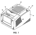
- a solid ink, or phase change ink printer 10 includes an outer housing having a top surface 12 and side surfaces 14.
- a user interface such as a front panel display screen 16 displays information concerning the status of the printer, and user instructions.
- Buttons 18 or other control elements may be adjacent the user interface window, or at other locations on the printer, to permit user interaction with the printer.
- the printing mechanism (not shown) is contained inside the housing. Such a printing mechanism is described in United States Patent No. 5,805,191, entitled Surface Application System, to Jones et al., and United States Patent No. 5,455,604, entitled Ink Jet Printer Architecture and Method, to Adams et al.
- An ink feed system delivers solid ink to the printing mechanism.
- the ink feed system may be contained under the top surface of the housing.
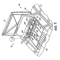
- the top surface of the housing includes a hinged top cover 20 that opens to reveal the ink feed system, and shown in Figure 2.
- the ink access cover 20 is attached to an ink load linkage 22 so that when the ink access cover 20 is raised, the ink load linkage 22 slides and pivots to an ink load position.
- the interaction of the ink access cover and the ink load linkage element is similar to that described in United States Patent No. 5,861,903 for an Ink Feed System, issued January 19, 1999 to Crawford et al.
- Opening the ink access cover 20 reveals a key plate 26 having keyed openings 24.
- the keyed openings provide access to a feed chute comprising several individual feed channels 28. Each keyed opening provides access to an insertion end of one of the several individual feed channels 28 of the solid ink feed system.
- a color printer typically uses four colors of ink (black, cyan, magenta, and yellow). Each color corresponds to one of the feed channels.
- the key plate has four keyed openings 24A, 24B, 24C, and 24D. Each keyed opening 24A, 24B, 24C, 24D of the key plate 26 has a unique shape.
- the ink sticks 30 of the color for that feed channel have a shape corresponding to the shape of the keyed opening 24.
- the lateral sides of the key plate openings and the lateral sides of the ink sticks may have corresponding shapes.
- the keyed openings and corresponding ink stick shapes are designed to ensure that only ink sticks of the proper color are inserted into each ink stick feed channel.
- a visually recognizable symbol 23 such as a numeral, can be applied to or formed in the housing adjacent the keyed opening. This visually recognizable symbol aids the printer user in identifying particular keyed openings and their corresponding feed channels.
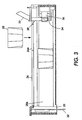
- each feed channel 28 is a longitudinal feed channel designed to deliver ink sticks 30 of a particular color to a corresponding melt plate 32.
- first feed channel 28A is shown in Figure 3, all the feed channels are identical for purposes of the following description.
- Each feed channel in the particular example illustrated includes a push block 34 driven by a constant force spring 36 to push the individual ink sticks 30 along the length of the longitudinal feed channel 28 toward the melt plates 32 that are at the melt end of each feed channel.
- the constant force spring 36 can be a flat spring with its face oriented along a substantially vertical axis.
- the feed channel has a longitudinal dimension from the insertion end to the melt end, and a lateral dimension, substantially perpendicular to the longitudinal dimension.
- the feed channel receives ink sticks inserted at the insertion end.
- the feed channel has sufficient longitudinal length that multiple ink sticks can be inserted into the feed channel.
- Each feed channel delivers ink sticks along the longitudinal length or feed direction of the channel to the corresponding melt plate at the melt end of the feed channel.
- the melt end of the feed channel is adjacent the melt plate.
- the melt plate melts the solid ink stick into a liquid form. The melted ink drips through a gap 33 between the melt end of the feed channel and the melt plate, and into a liquid ink reservoir (not shown).
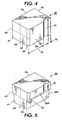
- the ink stick 30 for use in the feed system is illustrated in Figure 4.
- the ink stick is formed of a three dimensional ink stick body.
- a substantially cubic ink stick body is illustrated in Figure 4.
- the ink stick body illustrated has a bottom, represented by a general bottom surface 52, and a top, represented by a general top surface 54.
- the top and bottom surfaces are shown substantially parallel one another.
- the surfaces of the ink stick body need not be flat, nor need they be parallel or perpendicular one another. Nevertheless, these descriptions will aid the reader in visualizing, even though the surfaces may have three dimensional topography, or be angled with respect to one another.
- the ink stick body also has a plurality of side extremities, such as side surfaces 56, 61, 62.
- the illustrated example includes four side surfaces, including two end surfaces 61, 62 and two lateral side surfaces 56.
- the lateral side surfaces 56 are substantially parallel one another, and are substantially perpendicular to the top and bottom surfaces 52, 54.
- the end surfaces 61, 62 are also substantially parallel one another, and substantially perpendicular to the top and bottom surfaces, and to the lateral side surfaces.
- the ink stick is configured to fit into the feed channel of the feed channel with the two lateral side surfaces 56 of the ink stick body oriented along the longitudinal feed direction of the feed channel. With the substantially cubic ink stick shape illustrated, the end surfaces are thus oriented along the transverse or lateral dimension of the feed channel.
- One of the end surfaces 61 is a front or leading end surface, and the other end surface 62 is a rear or trailing end surface.
- the bottom surface has lateral edges 58 at which the bottom surface 52 intersects the lateral side surfaces 56.
- the ink stick body may be formed by pour molding, injection molding, compression molding, or other known techniques.
- the ink stick body can also be formed in any of numerous other shapes.
- Figure 5 illustrates an example of the ink stick body in which the lateral side surfaces 56 are stepped or segmented.
- the lower portion of the body adjacent the bottom surface is narrower in the lateral dimension than the upper portion of the ink stick body adjacent the top surface.
- the lower portion of the ink stick body in the example of Figure 5 is approximately 5 - 30% narrower than the upper portion of the ink stick body.
- the ink stick body has a lateral center of gravity 63 between the lateral side surfaces of the body, and a vertical center of gravity 64 between the top and bottom surfaces. If the ink stick body has a substantially uniform weight density, the lateral center of gravity is approximately midway between the lateral side surfaces 56 of the ink stick body.
- the outermost lateral dimension of the ink stick body is only fractionally smaller than the lateral dimension of the ink stick feed channel 28.
- the ink stick body has a longitudinal dimension between the end surfaces, including keying features, of between approximately 0.8 and 2.0 inches (20 - 51 mm), such as 1.2 inch (30 mm).
- the ink stick body has a lateral dimension between the lateral extremities of between approximately 1.0 and 2.0 inches (25 - 51 mm), such as 1.5 inch (38 mm).
- the ink stick body has a vertical dimension between the top and bottom surfaces of between approximately 0.8 and 1.6 inches (20 - 41 mm), such as 1.3 inches (34 mm).
- the lateral dimension of the ink stick feed channel is approximately 0.004 to 0.2 inches (0.1 - 5.0 mm) wider than the lateral dimension of the ink stick body.
- the ink stick body remains substantially upright in the feed channel.
- the ink stick body has an outer perimeter that is substantially horizontal around the largest horizontal cross section of the ink stick body.
- the outer perimeter is substantially uniform from the bottom surface to the top surface of the ink stick body.
- the horizontal outer perimeter substantially corresponds with the top surface 54 of the ink stick body.
- the outermost lateral side portions 56A of the ink stick body form longitudinal ink stick body perimeter segments that extend substantially parallel with the longitudinal feed direction of the feed channel when the ink stick is inserted into the feed channel.
- the ink sticks shown in Figures 4 and 5 have a substantially horizontal cross-sectional shape, formed of the perimeter of the ink stick body as when the ink stick is viewed from above the top surface, corresponding to the shape of the keyed opening 24 of the corresponding feed channel for that particular color.
- the ink stick body includes a key element 70 of a particular predetermined size, shape, and location on the outer perimeter of the ink stick body.
- the ink stick key element 70 is formed in the longitudinal perimeter segment formed by the outermost portion of the lateral side surface.
- the ink stick key element 70 matches a complementary key 72 formed in the perimeter of the keyed opening 24 in the key plate.
- Each color for a printer has a unique arrangement of one or more key elements in the outer perimeter of the ink stick to form a unique cross-sectional shape for that particular color ink stick.
- the combination of the keyed openings 24 in the key plate 26 and the keyed shapes of the ink sticks 30 (formed by the key elements 70) insure that only ink sticks of the proper color are inserted into each feed channel.
- a set of ink sticks is formed of an ink stick of each color, with a unique key arrangement for ink sticks of each color.
- the key element 70 is a vertical recess or notch formed in one of the lateral side surfaces 56 of the ink stick body.
- the corresponding complementary key 72 on the perimeter of the keyed opening 24 is a complementary protrusion into the opening.
- An inwardly directed key element, such as a notch, in the ink stick body provides improved ability to exclude incorrect ink sticks. Only an ink stick with a recess of that particular shape, location, and size (or larger) will fit through the keyed opening in the key plate having a key consisting of a corresponding protrusion from the edge of the keyed opening.
- a recessed key element on the ink stick body allows much of the lateral side surfaces 56 of the ink stick body to be substantially flat.
- the sections of the lateral side surfaces 56 adjacent the corners with the end surfaces 61, 62 of the ink stick body can be flush with one another, and be the outermost lateral portions of the lateral side surface.
- the outermost lateral portions of the lateral side surfaces are the portions that tend to interact with the side walls of the feed channel that form the feed channel. Having the end sections of the lateral side surfaces as the outermost portions of the ink stick provides balanced sections that help the ink stick retain its proper orientation as the ink stick moves through the feed channel.
- the key element extends at least approximately 0.16 inch (4mm) into the ink stick body.
- the key element 70 extends along the entire height of the lateral surface.
- the ink stick can pass through the keyed opening having a protrusion at a corresponding position of the keyed opening.
- the example of Figure 5 has the key element extend only along the portion of Figure 5 has the key element extend only along the portion of the lateral side surface 56A of the wider portion of the ink stick.
- the corresponding key 72 on the keyed opening 24 of the key plate 26 does not extend far enough into the opening to require that the key element 70 be included in the narrower portion of the ink stick body.
- the key element 70 on the ink stick body has a particular position with respect to the other perimeter segment of the ink stick body.
- the key element has a particular spatial relationship with respect to the edges at which the perimeter segment containing the key element intersects other perimeter segments of the ink stick body.
- the key element 70 on the side surface 56 has a particular position with other surfaces of the ink stick body, such as the end surfaces 61, 62.
- the ink stick key element is located a leading distance 74 from the leading end surface 61 of the ink stick body, and a trailing distance 76 from the trailing end surface 62 of the ink stick body.
- the leading distance 74 is substantially greater than the trailing distance 76.
- the leading distance may be three times the trailing distance.
- Figure 6 is a top view of the ink stick of Figure 4.
- a top view of the ink stick of Figure 5 is identical.
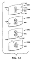
- Figures 7, 8, and 9 are top views of ink sticks that may be included in a multi-color set of ink sticks for use in the printer shown in Figures 1 - 3.
- a set of ink sticks provides a unique one-to-one match between a particular color ink stick and the keyed openings providing access to the four ink stick feed channels 28.
- Such one-to-one match is provided by including a key element 70 of a single predetermined size and shape at different locations around the outer perimeter of the ink stick body.
- an ink stick with the key element 70A positioned as shown in Figure 6 can be inserted into the first keyed opening 24A in the key plate shown in Figure 2, but cannot be inserted into any of the other keyed openings 24B, 24C, 24D.
- the keys 72B, 72C, 72D in the keyed openings 24B, 24C, 24D of the key plate and corresponding to the key element positions shown in the ink sticks 30B, 30C, 30D of Figures 7, 8, and 9 will block the ink stick 30A of Figure 6.
- the ink stick 30B having the key element 70B positioned as shown in Figure 7 can be inserted into the second keyed opening 24B of the key plate shown in Figure 2, but not into the other keyed openings 24A, 24C, 24D.
- the ink sticks having the key elements 70C, 70D positioned as shown in Figures 8 and 9 can be inserted into and only into the third and fourth key openings 24C, 24D, which correspond to the third and fourth ink stick feed channels.
- the key elements 70A, 70B, 70C, 70D provide discrimination among the different feed channels to stop the user from inserting an ink stick into the incorrect ink stick feed channel.
- the key elements 70A, 70B, 70C, 70D are of substantially the same size and shape as one another, but are in different positions around the perimeter of the ink stick body.
- the key element 70C in the third ink stick 30C is formed in the same lateral side surface 56 as the key element 70A in the first ink stick 30A.
- the leading distance 74C from the leading end surface 61 to the key element 70C of the third ink stick 30C is significantly greater than the trailing distance 76C from the key element 70C to the trailing end surface 62.
- the ratio of the leading distance 74C to trailing distance 76C for the third ink stick 30C could be the inverse of the ratio of the leading distance 74A to trailing distance 76A for the first ink stick 30A.
- More than one key element 70 can be included on a side surface 56 of the ink stick body.
- at least some of the key elements are on different sides of the ink stick horizontal perimeter.
- the key element 70A of the first ink stick is on a first section of the perimeter
- the key element 70B of the second ink stick is on a second section of the perimeter.
- the first and second sections of the perimeter do not correspond or align with one another when the first and second ink sticks 30A, 30B are aligned with one another.
- An orientation feature 65 in each ink stick is useful to prevent erroneous ink insertion when the key element patterns (size and position) are symmetrical.
- the orientation feature illustrated is a corner notch in each ink stick. Referring to Figures 6 and 7, the orientation feature prohibits incorrect insertion of the first ink stick 30A into the second keyed opening 24B if the leading distance 74A and trailing distance 76A of the first ink stick are the same as the trailing distance 76B and leading distance 74B of the second ink stick.
- Those skilled in the art will identify numerous other types and configurations of features to ensure that ink sticks are inserted into the key opening with the correct orientation.
- the orientation feature can be provided by positioning the key elements 70 so that the leading and trailing distances on different ones of the ink sticks are not symmetrical.
- the orientation feature can be provided by having the leading distance 74A of the first ink stick 30A a different length than the trailing distance 76B of the second ink stick 30B and the trailing distance 76A of the first ink stick 30A a different length than the leading distance 74B of the second ink stick 30B.
- the orientation feature can be provided by a nesting feature in which a protruding element from the leading end surface 61 of one ink stick nests with a recessed element in the trailing end surface 62 of an adjacent ink stick.
- the common shape and size of the key elements for the ink sticks of a particular set of ink sticks for a printer facilitates manufacture of the ink sticks, and enhances the "family" appearance of the set of ink sticks for that particular printer.
- Different shapes and/or sizes of key elements can be used to differentiate ink sticks intended for different models of printers. For example, one printer could use triangular ink stick key elements 70. A different printer model could use semicircular ink stick key elements (not shown). Yet a different printer model could use rectangular ink stick key elements (not shown).
- the ink stick key elements need not all be formed in the longitudinal perimeter segments formed on the lateral side surfaces of the ink stick body. Key elements can also be formed in perimeter segments of the ink stick body that are at least partially transverse longitudinal feed direction. For example, key elements can be formed in the perimeter segments formed by the outermost portions of the end surfaces 61, 62 of the ink stick body.
- the ink stick body can have a number of sides other than four.
- the ink stick body can be formed with three, five, or virtually any number of side surfaces. These side surfaces need not be equal in length, nor is the ink stick body necessarily symmetrical about the lateral or vertical centers of gravity.
- the ink stick body can have surfaces that are curved.
- the ink stick body can have a cylindrical shape, with the axis of the cylinder parallel the longitudinal feed direction of the feed channel 28, parallel the lateral dimension of the feed channel 28, or perpendicular to both the longitudinal feed direction and the lateral dimension (vertical).
- the ink stick body can also be formed in shapes other than a cubic rectangle.
- the ink stick can have an elliptical horizontal cross sectional shape, a shape having multiple straight linear sides, or even a combination of curved and linear sides.
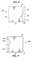
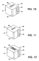
- an additional feature that reduces the possibility of incorrectly inserting an ink stick of one color into the feed channel intended for a different color is to include a visually recognizable symbol or mark 80 on the substantially horizontal top surface 54 of the ink block, as shown in Figures 10, 11, and 12.
- a visually recognizable symbol is a mark that conveys meaning to, or is easily recognizable by, a printer user.
- the visually recognizable symbol 80 is formed on the surface of the ink stick body with a vertical dimension, so that it is seen as three dimensional to the user.
- the symbol 80 can be raised or embossed on the top surface, as shown in Figure 10.
- the symbol could alternatively be impressed or debossed into the horizontal top surface of the ink stick block, as shown in Figure 11.
- a set of ink sticks for the printer shown in Figures 1 - 3 has the ink stick of the appropriate color identified with an alphanumeric character 80A, 80B, 80C, 80D corresponding to the particular keyed opening 24A, 24B, 24C, 24D leading to the appropriate feed channel 28 for that particular color of ink.
- the visually recognizable symbol 80 on the ink stick can match the visually recognizable symbol 23 adjacent the corresponding keyed opening.
- An ink stick 30A with a key element 70A as shown in Figure 6 for fitting through the first keyed opening 24A of the key plate is marked with, for example, the visually recognizable numeral "1.”
- An ink stick 30B with a key element 70B as shown in Figure 7 for fitting through the second keyed opening 24B of the key plate is marked with the visually recognizable numeral "2.”
- Ink sticks 30C, 30D with key elements 70C, 70D as shown in Figures 8 and 9 for fitting through the third and fourth keyed openings 24C, 24D of the key plate are marked with the visually recognizable numerals "3" and "4" respectively.
- the three dimensional visually recognizable symbol 80 could be a letter indicating the color of the ink stick (i.e., "C” for cyan, “M” for magenta, "Y” for yellow, and "K” for black).
- Other symbols that convey meaning or can be matched with symbols can be used. For distinguishing among feed channels (and their corresponding keyed openings), in some instances only a portion of the symbol need differ between ink sticks of an ink stick set.
- the visually recognizable symbol 80 can be formed on any of the surfaces of the ink stick body.
- the visually recognizable symbol is formed on the top surface 54 of the ink stick body, the symbol aids the user in orienting the ink for insertion through the insertion keyed openings, and remains visible to the printer user as the user inserts the ink stick through the opening 24 of the key plate 26. More than one symbol may be desired on each ink stick. For example, an alphanumeric logo could further increase the ease of correctly orienting the ink stick for insertion through the opening 24.
- Figure 12 shows that additional information besides the identification of the correct ink stick keyed opening can be provided on one or more of the surfaces of the ink stick body.
- the visually recognizable symbol or mark 80 comprises the brand name of the ink sticks, which is formed in the substantially horizontal upper surface of the ink stick body.
- Visually recognizable characters are either embossed or debossed in the ink stick body surface to provide a three dimensional presentation of information.
- Visually recognizable symbols that convey meaning, such as alphanumeric characters can provide a variety of information, such as the printer model for which the ink sticks are intended, or additional color information. Such symbols reduce the likelihood of a printer user inserting ink sticks into the incorrect model printer.
- ink sticks can have shapes other than rectangular.
- each ink stick 130 has a pair of substantially flat lateral side surfaces 156 that curve into curved end surfaces 161, 162 to provide a "pillow" shape.
- the end surfaces could be substantially flat, with curved lateral side surfaces.
- the ink sticks can be formed in numerous other shapes with different numbers of side surfaces, and various combinations of curved and flat surfaces.
Claims (10)
- Ein Satz von Tintenstiften (30A, 30B, 30C, 30D) für die Verwendung in einem Festtinten-Zuführsystem eines Tintenstrahldruckers (10) für phasenändernde Tinte, wobei das Festtinten-Zuführsystem eine Vielzahl von Zuführkanälen (28) aufweist, wobei der Satz von Tintenstiften umfasst:eine Vielzahl von Tintenstiften;wobei jeder der Tintenstifte umfasst:einen Tintenstiftkörper, der eine allgemeine Deckfläche (54) aufweist,gekennzeichnet durchein oder mehrere visuell erkennbare Symbole (80), die auf der Deckfläche (54) des Tintenstiftes ausgebildet sind;wobei mindestens ein Abschnitt von jedem der visuell erkennbaren Symbole eine Ausdehnung in einer Richtung senkrecht zu der Deckfläche aufweist.
- Der Satz von Tintenstiften gemäß Anspruch 1, wobei mindestens ein Abschnitt des visuell erkennbaren Symbols (80) auf jedem der Tintenstifte des Satzes unterschiedlich ist.
- Der Satz von Tintenstiften gemäß Anspruch 1, wobei das visuell erkennbare Symbol (80) auf jedem der Tintenstifte einem vorbestimmten aus der Vielzahl von Zuführkanälen (28) des Festtinten-Zuführsystems entspricht.
- Der Satz von Tintenstiften gemäß Anspruch 1, wobei die Deckfläche (54) von jedem der Tintenstiftkörper mindestens einigermaßen horizontal ist.
- Der Satz von Tintenstiften gemäß Anspruch 1, wobei das visuell erkennbare Symbol (80) in die Deckfläche (54) eingeprägt ist.
- Der Satz von Tintenstiften gemäß Anspruch 1, wobei das visuell erkennbare Symbol (80) auf der Deckfläche (54) erhaben ist.
- Ein Tintenstift (30) für die Verwendung in einem Festtinten-Zuführsystem eines Tintenstrahldruckers (10) für phasenändernde Tinte, wobei der Tintenstift umfasst:einen Tintenstiftkörper, der eine Deckfläche (54) aufweist,gekennzeichnet durchein visuell erkennbares Symbol (80), das auf der Deckfläche (54) ausgebildet ist;wobei das visuell erkennbare Symbol (80) eine Ausdehnung in einer Richtung senkrecht zu der Deckfläche aufweist.
- Tintenstift gemäß Anspruch 7, wobei das visuell erkennbare Symbol (80) in die Deckfläche (54) eingeprägt ist.
- Der Tintenstift gemäß Anspruch 7, wobei das visuell erkennbare Symbol (80) auf der Deckfläche (54) erhaben ist.
- Ein Verfahren zum Ausbilden eines Satzes von Tintenstiften (30A, 30B, 30C, 30D) für die Verwendung in einem Festtinten-Zuführsystem eines Tintenstrahldruckers (10) für phasenändernde Tinte, wobei das Verfahren umfasst:Ausbilden einer Vielzahl von Tintenstiften, wobei jeder Tintenstift einen Tintenstiftkörper umfasst, der eine im Wesentlichen horizontale Deckfläche (54) aufweist;gekennzeichnet durchauf der horizontalen Deckfläche (54) jedes Tintenstiftes des Satzes, ausbilden eines eindeutigen, visuell erkennbaren Symbols (80), das eine Ausdehnung in einer Richtung senkrecht zu der Deckfläche (54) aufweist.
Applications Claiming Priority (2)
| Application Number | Priority Date | Filing Date | Title |
|---|---|---|---|
| US10/135,067 US6857732B2 (en) | 2002-04-29 | 2002-04-29 | Visible identification of solid ink stick |
| US135067 | 2002-04-29 |
Publications (2)
| Publication Number | Publication Date |
|---|---|
| EP1359024A1 EP1359024A1 (de) | 2003-11-05 |
| EP1359024B1 true EP1359024B1 (de) | 2007-01-17 |
Family
ID=29215638
Family Applications (1)
| Application Number | Title | Priority Date | Filing Date |
|---|---|---|---|
| EP03009621A Expired - Fee Related EP1359024B1 (de) | 2002-04-29 | 2003-04-29 | Sichtbare Erkennungselemente auf festen Tintenstiften |
Country Status (5)
| Country | Link |
|---|---|
| US (2) | US6857732B2 (de) |
| EP (1) | EP1359024B1 (de) |
| JP (1) | JP2003312014A (de) |
| BR (1) | BR0301259B1 (de) |
| DE (1) | DE60311175T2 (de) |
Families Citing this family (39)
| Publication number | Priority date | Publication date | Assignee | Title |
|---|---|---|---|---|
| US6722764B2 (en) * | 2002-04-29 | 2004-04-20 | Xerox Corporation | Feed guidance and identification for ink stick |
| US6857732B2 (en) * | 2002-04-29 | 2005-02-22 | Xerox Corporation | Visible identification of solid ink stick |
| US7299984B2 (en) * | 2003-08-21 | 2007-11-27 | Pitney Bowes Inc. | Postage indicia including encoded ink characteristic data |
| JP4341688B2 (ja) * | 2006-04-12 | 2009-10-07 | セイコーエプソン株式会社 | 液体収容容器 |
| US7874661B2 (en) | 2006-06-22 | 2011-01-25 | Xerox Corporation | Solid ink stick with coded markings and method and apparatus for reading markings |
| US7553008B2 (en) | 2006-06-23 | 2009-06-30 | Xerox Corporation | Ink loader for interfacing with solid ink sticks |
| US7857439B2 (en) | 2006-06-23 | 2010-12-28 | Xerox Corporation | Solid ink stick with interface element |
| US7517072B2 (en) | 2006-06-23 | 2009-04-14 | Xerox Corporation | Solid ink stick with enhanced differentiation |
| US7537326B2 (en) | 2006-06-23 | 2009-05-26 | Xerox Corporation | Solid ink stick with coded sensor feature |
| US7648232B2 (en) * | 2006-07-12 | 2010-01-19 | Xerox Corporation | Solid ink stick with reliably encoded data |
| US7631963B2 (en) * | 2006-08-01 | 2009-12-15 | Xerox Corporation | Method of forming solid ink stick with coded mark |
| US7790092B2 (en) * | 2006-10-11 | 2010-09-07 | Xerox Corporation | Flow fill manufacturing of solid ink sticks with top surface conditioning |
| US7682010B2 (en) * | 2006-10-11 | 2010-03-23 | Xerox Corporation | Solid ink stick with coating |
| US7968035B2 (en) * | 2006-10-11 | 2011-06-28 | Xerox Corporation | Forged ink stick fabrication from in-line extrusion |
| US7874826B2 (en) | 2006-10-11 | 2011-01-25 | Xerox Corporation | Solid ink stick fabrication by extrusion, roll forming and swaging |
| US7854501B2 (en) * | 2006-11-07 | 2010-12-21 | Xerox Corporation | Common side insertion keying for phase change ink sticks |
| US7976144B2 (en) * | 2006-11-21 | 2011-07-12 | Xerox Corporation | System and method for delivering solid ink sticks to a melting device through a non-linear guide |
| US7883195B2 (en) * | 2006-11-21 | 2011-02-08 | Xerox Corporation | Solid ink stick features for printer ink transport and method |
| US7798624B2 (en) | 2006-11-21 | 2010-09-21 | Xerox Corporation | Transport system for solid ink in a printer |
| US7794072B2 (en) | 2006-11-21 | 2010-09-14 | Xerox Corporation | Guide for printer solid ink transport and method |
| US7722177B2 (en) * | 2006-12-22 | 2010-05-25 | Xerox Corporation | System for loading ink sticks configured for lateral anti-skewing |
| US7824027B2 (en) * | 2007-09-11 | 2010-11-02 | Xerox Corporation | Solid ink stick with anti jam edge bevel |
| US7909445B2 (en) * | 2007-09-11 | 2011-03-22 | Xerox Corporation | Solid ink stick delivery system with static constraints, strategic barriers and breakage controls |
| US8016403B2 (en) * | 2007-10-03 | 2011-09-13 | Xerox Corporation | Solid ink stick with visual orientation indicator |
| US7976118B2 (en) | 2007-10-22 | 2011-07-12 | Xerox Corporation | Transport system for providing a continuous supply of solid ink to a melting assembly in a printer |
| US7891792B2 (en) | 2007-11-06 | 2011-02-22 | Xerox Corporation | Solid ink stick with transition indicating region |
| US7887173B2 (en) | 2008-01-18 | 2011-02-15 | Xerox Corporation | Transport system having multiple moving forces for solid ink delivery in a printer |
| US7857440B2 (en) * | 2008-01-18 | 2010-12-28 | Xerox Corporation | Visual identification of solid ink sticks |
| US7837317B2 (en) * | 2008-02-15 | 2010-11-23 | Xerox Corporation | Solid ink stick with witness mark |
| US8025385B2 (en) * | 2008-07-16 | 2011-09-27 | Xerox Corporation | Ink sticks with visually discernible feature patterns |
| US7971980B2 (en) * | 2008-07-22 | 2011-07-05 | Xerox Corporation | Solid ink stick with reflection features |
| US8052265B2 (en) * | 2008-09-22 | 2011-11-08 | Xerox Corporation | System and method for verifying position of an object before identifying the object |
| US8096647B2 (en) * | 2008-09-22 | 2012-01-17 | Xerox Corporation | Solid ink sticks having a verification interlock for verifying position of a solid ink stick before identifying the ink stick |
| US8240830B2 (en) | 2010-03-10 | 2012-08-14 | Xerox Corporation | No spill, feed controlled removable container for delivering pelletized substances |
| US8366255B2 (en) | 2010-06-02 | 2013-02-05 | Xerox Corporation | Solid ink stick with retrieval feature |
| US8814336B2 (en) * | 2011-12-22 | 2014-08-26 | Xerox Corporation | Solid ink stick configuration |
| US8876265B2 (en) | 2012-06-28 | 2014-11-04 | Xerox Corporation | Ink stick transport system |
| US8727478B2 (en) | 2012-10-17 | 2014-05-20 | Xerox Corporation | Ink loader having optical sensors to identify solid ink sticks |
| US8777386B2 (en) | 2012-10-17 | 2014-07-15 | Xerox Corporation | Solid ink stick having identical identifying features on a plurality of edges |
Family Cites Families (15)
| Publication number | Priority date | Publication date | Assignee | Title |
|---|---|---|---|---|
| US5455604A (en) | 1991-04-29 | 1995-10-03 | Tektronix, Inc. | Ink jet printer architecture and method |
| US5223860A (en) * | 1991-06-17 | 1993-06-29 | Tektronix, Inc. | Apparatus for supplying phase change ink to an ink jet printer |
| USD346821S (en) * | 1992-07-27 | 1994-05-10 | Dataproducts Corporation | Stepped diameter recessed solid ink pellet |
| US5805191A (en) | 1992-11-25 | 1998-09-08 | Tektronix, Inc. | Intermediate transfer surface application system |
| US5510821B1 (en) * | 1994-09-20 | 2000-05-02 | Tektronix Inc | Solid ink stick |
| JPH0939265A (ja) | 1995-07-29 | 1997-02-10 | Seiko Epson Corp | プリンタにおけるインクカートリッヂ並びにその識別装置 |
| US5734402A (en) * | 1996-03-07 | 1998-03-31 | Tekronix, Inc. | Solid ink stick feed system |
| US5861903A (en) * | 1996-03-07 | 1999-01-19 | Tektronix, Inc. | Ink feed system |
| US5917528A (en) | 1996-09-05 | 1999-06-29 | Tektronix, Inc. | Solid ink stick supply apparatus and method |
| US5988805A (en) * | 1997-03-10 | 1999-11-23 | Tektronix, Inc | Chiral shaped ink sticks |
| USD403699S (en) * | 1997-03-10 | 1999-01-05 | Tektronix, Inc. | Solid ink stick for a color printer |
| JP3455798B2 (ja) | 1999-02-04 | 2003-10-14 | カシオ計算機株式会社 | インクジェット記録装置及びそれに用いるインクカートリッジとインク補充具 |
| US6874880B2 (en) | 2002-04-29 | 2005-04-05 | Xerox Corporation | Solid ink stick with identifiable shape |
| US6755517B2 (en) | 2002-04-29 | 2004-06-29 | Xerox Corporation | Alignment feature for solid ink stick |
| US6857732B2 (en) * | 2002-04-29 | 2005-02-22 | Xerox Corporation | Visible identification of solid ink stick |
-
2002
- 2002-04-29 US US10/135,067 patent/US6857732B2/en not_active Expired - Lifetime
-
2003
- 2003-04-25 JP JP2003120811A patent/JP2003312014A/ja active Pending
- 2003-04-28 BR BRPI0301259-0A patent/BR0301259B1/pt not_active IP Right Cessation
- 2003-04-29 EP EP03009621A patent/EP1359024B1/de not_active Expired - Fee Related
- 2003-04-29 DE DE60311175T patent/DE60311175T2/de not_active Expired - Lifetime
-
2004
- 2004-11-01 US US10/980,103 patent/US7063412B2/en not_active Expired - Fee Related
Also Published As
| Publication number | Publication date |
|---|---|
| BR0301259B1 (pt) | 2011-08-23 |
| EP1359024A1 (de) | 2003-11-05 |
| DE60311175D1 (de) | 2007-03-08 |
| US7063412B2 (en) | 2006-06-20 |
| US20030202076A1 (en) | 2003-10-30 |
| US20050088499A1 (en) | 2005-04-28 |
| DE60311175T2 (de) | 2007-05-10 |
| US6857732B2 (en) | 2005-02-22 |
| JP2003312014A (ja) | 2003-11-06 |
| BR0301259A (pt) | 2004-09-08 |
Similar Documents
| Publication | Publication Date | Title |
|---|---|---|
| EP1359024B1 (de) | Sichtbare Erkennungselemente auf festen Tintenstiften | |
| EP1366909B1 (de) | Kodierungsmerkmal für festen Tintenstift | |
| EP0863009B1 (de) | Optische Kodierung eines Wartungsmoduls für einen Druckkopf | |
| US6986570B2 (en) | Feed guidance and identification for ink stick | |
| JP4308567B2 (ja) | 識別可能な固体インクスティック | |
| EP1366915B1 (de) | Vorrichtung zum Laden und Zuführen für feste Tinte | |
| EP1366916B1 (de) | Vorrichtung zum Laden und Zuführen für feste Tinte | |
| JP4341688B2 (ja) | 液体収容容器 | |
| US6705710B2 (en) | Load and feed apparatus for solid ink | |
| US6719413B2 (en) | Load and feed apparatus for solid ink | |
| JP2003312019A (ja) | ソリッドインク棒供給のための供給チャンネルキーイング | |
| US6761444B2 (en) | Channel keying for solid ink stick insertion | |
| US6565200B1 (en) | Load and feed apparatus for solid ink | |
| EP1366917B1 (de) | Vorrichtung zum Laden und Zuführen für feste Tinte | |
| JP4189690B2 (ja) | 液体収容容器 | |
| US7108363B2 (en) | Keying elements for solid ink loader | |
| US20080049083A1 (en) | Liquid container | |
| US8651645B2 (en) | Print cartridge identification system and method | |
| EP2045081B1 (de) | Festtintenstift mit visueller Orientierungsanzeige | |
| US7871159B2 (en) | Ink loader with adjustable insertion openings | |
| JP6684362B2 (ja) | プリントカートリッジ取付領域および印刷装置 |
Legal Events
| Date | Code | Title | Description |
|---|---|---|---|
| PUAI | Public reference made under article 153(3) epc to a published international application that has entered the european phase |
Free format text: ORIGINAL CODE: 0009012 |
|
| AK | Designated contracting states |
Kind code of ref document: A1 Designated state(s): AT BE BG CH CY CZ DE DK EE ES FI FR GB GR HU IE IT LI LU MC NL PT RO SE SI SK TR |
|
| AX | Request for extension of the european patent |
Extension state: AL LT LV MK |
|
| 17P | Request for examination filed |
Effective date: 20040506 |
|
| AKX | Designation fees paid |
Designated state(s): DE FR GB |
|
| 17Q | First examination report despatched |
Effective date: 20041018 |
|
| GRAP | Despatch of communication of intention to grant a patent |
Free format text: ORIGINAL CODE: EPIDOSNIGR1 |
|
| GRAS | Grant fee paid |
Free format text: ORIGINAL CODE: EPIDOSNIGR3 |
|
| GRAA | (expected) grant |
Free format text: ORIGINAL CODE: 0009210 |
|
| AK | Designated contracting states |
Kind code of ref document: B1 Designated state(s): DE FR GB |
|
| REG | Reference to a national code |
Ref country code: GB Ref legal event code: FG4D |
|
| REF | Corresponds to: |
Ref document number: 60311175 Country of ref document: DE Date of ref document: 20070308 Kind code of ref document: P |
|
| ET | Fr: translation filed | ||
| PLBE | No opposition filed within time limit |
Free format text: ORIGINAL CODE: 0009261 |
|
| STAA | Information on the status of an ep patent application or granted ep patent |
Free format text: STATUS: NO OPPOSITION FILED WITHIN TIME LIMIT |
|
| 26N | No opposition filed |
Effective date: 20071018 |
|
| REG | Reference to a national code |
Ref country code: FR Ref legal event code: PLFP Year of fee payment: 14 |
|
| REG | Reference to a national code |
Ref country code: FR Ref legal event code: PLFP Year of fee payment: 15 |
|
| PGFP | Annual fee paid to national office [announced via postgrant information from national office to epo] |
Ref country code: FR Payment date: 20170322 Year of fee payment: 15 |
|
| PGFP | Annual fee paid to national office [announced via postgrant information from national office to epo] |
Ref country code: GB Payment date: 20180321 Year of fee payment: 16 |
|
| PGFP | Annual fee paid to national office [announced via postgrant information from national office to epo] |
Ref country code: DE Payment date: 20180320 Year of fee payment: 16 |
|
| PG25 | Lapsed in a contracting state [announced via postgrant information from national office to epo] |
Ref country code: FR Free format text: LAPSE BECAUSE OF NON-PAYMENT OF DUE FEES Effective date: 20180430 |
|
| REG | Reference to a national code |
Ref country code: DE Ref legal event code: R119 Ref document number: 60311175 Country of ref document: DE |
|
| GBPC | Gb: european patent ceased through non-payment of renewal fee |
Effective date: 20190429 |
|
| PG25 | Lapsed in a contracting state [announced via postgrant information from national office to epo] |
Ref country code: DE Free format text: LAPSE BECAUSE OF NON-PAYMENT OF DUE FEES Effective date: 20191101 Ref country code: GB Free format text: LAPSE BECAUSE OF NON-PAYMENT OF DUE FEES Effective date: 20190429 |