EP1359017A1 - Bâton d'encre solide à plusieurs portions - Google Patents
Bâton d'encre solide à plusieurs portions Download PDFInfo
- Publication number
- EP1359017A1 EP1359017A1 EP03008881A EP03008881A EP1359017A1 EP 1359017 A1 EP1359017 A1 EP 1359017A1 EP 03008881 A EP03008881 A EP 03008881A EP 03008881 A EP03008881 A EP 03008881A EP 1359017 A1 EP1359017 A1 EP 1359017A1
- Authority
- EP
- European Patent Office
- Prior art keywords
- ink stick
- ink
- perimeter
- stick body
- feed channel
- Prior art date
- Legal status (The legal status is an assumption and is not a legal conclusion. Google has not performed a legal analysis and makes no representation as to the accuracy of the status listed.)
- Granted
Links
- 239000007787 solid Substances 0.000 title claims abstract description 52
- 238000003780 insertion Methods 0.000 claims abstract description 25
- 230000037431 insertion Effects 0.000 claims abstract description 25
- 230000008859 change Effects 0.000 claims abstract description 15
- 238000000034 method Methods 0.000 claims description 11
- 230000000295 complement effect Effects 0.000 abstract description 20
- 239000000155 melt Substances 0.000 description 33
- 238000005304 joining Methods 0.000 description 14
- 230000005484 gravity Effects 0.000 description 10
- 230000003993 interaction Effects 0.000 description 8
- 239000007788 liquid Substances 0.000 description 7
- 230000007246 mechanism Effects 0.000 description 6
- 239000003086 colorant Substances 0.000 description 5
- 230000009286 beneficial effect Effects 0.000 description 4
- 230000015572 biosynthetic process Effects 0.000 description 3
- 238000007373 indentation Methods 0.000 description 3
- 238000000748 compression moulding Methods 0.000 description 2
- 238000009472 formulation Methods 0.000 description 2
- 238000002844 melting Methods 0.000 description 2
- 230000008018 melting Effects 0.000 description 2
- 239000000203 mixture Substances 0.000 description 2
- 238000012986 modification Methods 0.000 description 2
- 230000004048 modification Effects 0.000 description 2
- 238000000465 moulding Methods 0.000 description 2
- 238000007639 printing Methods 0.000 description 2
- 230000008569 process Effects 0.000 description 2
- 238000007493 shaping process Methods 0.000 description 2
- 230000000007 visual effect Effects 0.000 description 2
- 241001465754 Metazoa Species 0.000 description 1
- 238000011109 contamination Methods 0.000 description 1
- 238000001816 cooling Methods 0.000 description 1
- 238000009795 derivation Methods 0.000 description 1
- 230000004069 differentiation Effects 0.000 description 1
- 238000009826 distribution Methods 0.000 description 1
- 230000000694 effects Effects 0.000 description 1
- 230000002708 enhancing effect Effects 0.000 description 1
- 230000007717 exclusion Effects 0.000 description 1
- 238000001746 injection moulding Methods 0.000 description 1
- 238000007641 inkjet printing Methods 0.000 description 1
- 230000002452 interceptive effect Effects 0.000 description 1
- 238000004519 manufacturing process Methods 0.000 description 1
- 239000008188 pellet Substances 0.000 description 1
- 229920006395 saturated elastomer Polymers 0.000 description 1
- 238000012876 topography Methods 0.000 description 1
Images


Classifications
-
- B—PERFORMING OPERATIONS; TRANSPORTING
- B41—PRINTING; LINING MACHINES; TYPEWRITERS; STAMPS
- B41J—TYPEWRITERS; SELECTIVE PRINTING MECHANISMS, i.e. MECHANISMS PRINTING OTHERWISE THAN FROM A FORME; CORRECTION OF TYPOGRAPHICAL ERRORS
- B41J2/00—Typewriters or selective printing mechanisms characterised by the printing or marking process for which they are designed
- B41J2/005—Typewriters or selective printing mechanisms characterised by the printing or marking process for which they are designed characterised by bringing liquid or particles selectively into contact with a printing material
- B41J2/01—Ink jet
- B41J2/17—Ink jet characterised by ink handling
- B41J2/175—Ink supply systems ; Circuit parts therefor
- B41J2/17593—Supplying ink in a solid state
Definitions
- the present invention relates generally to ink printers, the ink used in such ink printers, and the apparatus and method for feeding the ink into the printer.
- Solid ink or phase change ink printers conventionally receive ink in a solid form and convert the ink to a liquid form for jetting onto a receiving medium.
- the printer receives the solid ink either as pellets or as ink sticks in a feed channel. With solid ink sticks, the solid ink sticks are either gravity fed or spring loaded through the feed channel toward a heater plate. The heater plate melts the solid ink into its liquid form. In a printer that receives solid ink sticks, the sticks are either gravity fed or spring loaded into a feed channel and pressed against a heater plate to melt the solid ink into its liquid form.
- United States Patent No. 5,734,402 for a Solid Ink Feed System, issued March 31, 1998 to Rousseau et al.; and United States Patent No. 5,861,903 for an Ink Feed System, issued January 19, 1999 to Crawford et al. describe exemplary systems for delivering solid ink sticks into a phase change ink printer.
- An ink stick for use in a solid ink feed system of a phase change ink jet printer includes at least first and second three dimensional ink stick body portions.
- Each ink stick body portion includes a perimeter section that is substantially the same as a corresponding section of a keyed insertion opening in the solid ink feed system.
- Each ink stick body portion also includes a joint perimeter section that is the complement of the joint perimeter section of the other ink stick body portion, so that the first and second ink stick body portions fit together.
- a method of inserting an ink stick into a solid ink feed systems of a phase change ink jet printer includes providing first and second ink stick portions, each of which has a perimeter including a joint perimeter segment. The first and second ink stick portions are placed adjacent one another so that the joint perimeter segments of the two ink stick portions abut one another. The first and second ink stick portions are then inserted through an insertion opening in the solid ink feed system.
- Figure 1 is a perspective view of a phase change printer with the printer top cover closed.
- Figure 2 is an enlarged partial top perspective view of the phase change printer with the ink access cover open, showing a solid ink stick in position to be loaded into a feed channel.
- Figure 3 is a side sectional view of a feed channel of the solid ink feed system, taken along line 3 - 3 of Figure 2.
- Figure 4 is a sectional view of the ink stick feed system, taken along line 4 - 4 of Figure 2.
- Figure 5 is a perspective view of an embodiment of a solid ink stick.
- Figure 6 is a stylized representation of the derivation of an ink stick shape.
- Figure 7 is a top elevational view of a set of solid ink sticks.
- Figure 8 is a top elevational view of another set of solid ink sticks.
- Figure 9 is a view of a set of symbols for use in another set of solid ink sticks.
- Figure 10 is a top elevational view of a set of solid ink sticks incorporating the symbols of Figure 9.
- Figure 11 is a perspective view of another embodiment of a solid ink stick.
- Figure 12 is a top elevational view of another set of solid ink sticks.
- Figure 13 is a top elevational view of another set of solid ink sticks.
- Figure 14 is a top elevational view of another set of solid ink sticks.
- Figure 15 is an enlarged partial top perspective view of another embodiment of a phase change printer with the printer cover and the ink access cover open, showing a solid ink stick in position to be loaded into a feed channel.
- Figure 16 is a perspective view of a simplified ink stick body.
- Figure 17 is a bottom perspective view of another embodiment of a solid ink stick.
- Figure 18 is a top perspective view of the solid ink stick of Figure 17.
- Figure 19 is an enlarged partial top perspective view of the phase change printer with the printer cover and the ink access cover open, showing a solid ink stick in position to be loaded into a feed channel.
- Figure 20 is an enlarged partial top perspective view of the printer of Figure 1 with the solid ink stick feed system cover partially closed.
- Figure 21 is a side sectional view of a feed channel of a solid ink feed system, taken along line 4 - 4 of Figure 2.
- Figure 22 is a side sectional view of the feed channel of Figure 21 with ink sticks inserted into the feed channel and the ink load linkage closed.
- Figure 23 is a perspective view of one embodiment of an ink stick.
- Figure 24 is a top planar view of the ink stick of Figure 23.
- Figure 25 is a top planar view of two adjacent ink sticks in a feed channel in an ink feed system.
- Figure 26 is a top planar view of two adjacent ink sticks of a second embodiment of an aspect of the present invention.
- Figure 27 is a perspective view of another embodiment of an ink stick.
- Figure 28 is a perspective view of yet another embodiment of an ink stick.
- Figure 29 is a top planar view of another embodiment of an ink stick.
- Figure 30 is a perspective view of yet another embodiment of an ink stick.
- Figure 31 is a top planar view of the ink stick of Figure 30.
- Figure 32 is a perspective view of yet another embodiment of an ink stick.
- Figure 1 shows a solid ink, or phase change, ink printer 10 that includes an outer housing having a top surface 12 and side surfaces 14.
- a user interface such as a front panel display screen 16 displays information concerning the status of the printer, and user instructions.
- Buttons 18 or other control elements for controlling operation of the printer are adjacent the front panel display screen, or may be at other locations on the printer.
- An ink jet printing mechanism (not shown) is contained inside the housing.
- An example of the printing mechanism is described in United States Patent No. 5,805,191, entitled Surface Application System, to Jones et al., and United States Patent No. 5,455,604, entitled Ink Jet Printer Architecture and Method, to Adams et al.
- An ink feed system delivers ink to the printing mechanism.
- the ink feed system is contained under the top surface of the printer housing.
- the top surface of the housing includes a hinged ink access cover 20 that opens as shown in Figure 2, to provide the operator access to the ink feed system.
- the ink access cover 20 is attached to an ink load linkage element 22 so that when the printer ink access cover 20 is raised, the ink load linkage 22 slides and pivots to an ink load position.
- the interaction of the ink access cover and the ink load linkage element is described in United States Patent No. 5,861,903 for an Ink Feed System, issued January 19, 1999 to Crawford et al., though with some differences noted below.
- opening the ink access cover reveals a key plate 26 having keyed openings 24.
- Each keyed opening 24A, 24B, 24C, 24D provides access to an insertion end of one of several individual feed channels 28A, 28B, 28C, 28D of the solid ink feed system (see Figures 3 and 4).
- Each longitudinal feed channel 28 delivers ink sticks 130 of one particular color to a corresponding melt plate 32.
- Each feed channel has a longitudinal feed direction from the insertion end of the feed channel to the melt end of the feed channel.
- the melt end of the feed channel is adjacent the melt plate.
- the melt plate melts the solid ink stick into a liquid form.
- the melted ink drips through a gap 33 between the melt end of the feed channel and the melt plate, and into a liquid ink reservoir (not shown).
- the feed channels 28 have a longitudinal dimension from the insertion end to the melt end, and a lateral dimension, substantially perpendicular to the longitudinal dimension.
- Each feed channel in the particular embodiment illustrated includes a push block 34 driven by a driving force or element, such as a constant force spring 36 to push the individual ink sticks along the length of the longitudinal feed channel toward the melt plates 32 that are at the melt end of each feed channel.
- the tension of the constant force spring 36 drives the push block toward the melt end of the feed channel.
- the ink load linkage 22 is coupled to a yoke 38, which is attached to the constant force spring mounted in the push block 34.
- the attachment to the ink load linkage 22 pulls the push block 34 toward the insertion end of the feed channel when the ink access cover is raised to reveal the key plate 26.
- the constant force spring 36 can be a flat spring with is face oriented along a substantially vertical axis.
- Figure 4 is a cross-sectional view of an exemplary feed chute comprising a set of feed channels 28.
- a color printer typically uses four colors of ink (yellow, cyan, magenta, and black).
- Ink sticks 130 of each color are delivered through a corresponding individual one of the feed channels 28.
- the operator of the printer exercises care to avoid inserting ink sticks of one color into a feed channel for a different color.
- Ink sticks may be so saturated with color dye that it may be difficult for a printer operator to tell by the apparent color alone of the ink sticks which color is which. Cyan, magenta, and black ink sticks in particular can be difficult to distinguish visually based on color appearance.
- the key plate 26 has keyed openings 24 to aid the printer operator in ensuring that only ink sticks of the proper color are inserted into each feed channel.
- Each keyed opening 24 of the key plate has a unique shape.
- the ink sticks 130 of the color for that feed channel have a shape corresponding to the shape of the keyed opening.
- the keyed openings and corresponding ink stick shapes exclude from each ink feed channel ink sticks of all colors except the ink sticks of the proper color for that feed channel.
- the ink stick 130 for use in the feed system is illustrated in Figure 5.
- the ink stick is formed of a three dimensional ink stick body.
- the ink stick body illustrated has a bottom exemplified by a generally bottom surface 152 and a top exemplified by a generally top surface 154.
- the particular bottom surface 152 and top surface 154 illustrated are substantially parallel one another, although they can take on other contours and relative relationships.
- the surfaces of the ink stick body need not be flat, nor need they be parallel or perpendicular one another. However, these descriptions will aid the reader in visualizing, even though the surfaces may have three dimensional topography, or be angled with respect to one another.
- the ink stick body also has a plurality of side extremities, such as side surfaces 156A, 156B, 161, 162.
- the illustrated embodiment includes four side surfaces, including two end surfaces 161, 162 and two lateral side surfaces 156A, 156B.
- the basic elements of the lateral side surfaces 156A are substantially parallel one another, and are substantially perpendicular to the top and bottom surfaces 152, 154.
- the end surfaces 161, 162 are also basically substantially parallel one another, and substantially perpendicular to the top and bottom surfaces, and to the lateral side surfaces.
- One of the end surfaces 161 is a leading end surface, and the other end surface 162 is a trailing end surface.
- the basic side surfaces 156 and the end surfaces 161, 162 are modified with key and other shaping elements, as described in greater detail below.
- the ink stick body may be formed by pour molding, injection molding, compression molding, or other known techniques.
- the ink stick shown in Figure 5 has a substantially horizontal perimeter shape (as when the ink stick is viewed from above the top surface) corresponding to the shape of the keyed opening 24 of the corresponding feed channel for that particular color (see Figure 2).
- the horizontal cross-sectional shape of each color ink stick for a particular printer is different.
- the combination of the keyed openings 24 in the key plate 26 and the keyed shapes of the ink sticks 130 insure that only ink sticks of the proper color are inserted into each feed channel.
- a set of ink sticks is formed of an ink stick of each color, with a unique shape for ink sticks of each color.
- Figure 5 shows an example of an ink stick 130 in which the horizontal perimeter shape of the ink stick, as when the ink stick is viewed from above the top surface, forms a visually recognizable shape that identifies the ink stick with a particular feed channel is formed in the horizontal outer perimeter of the ink stick body.
- Figure 7 shows an exemplary set of such ink sticks.
- the substantially horizontal outer perimeter of each ink stick of the set forms a shape of a visually recognizable symbol, such as an alphanumeric character.
- the visually recognizable symbol is a shape that provides the printer operator with meaning that the operator can then use to associate the ink stick with a particular keyed opening or feed channel.
- the printer operator can correlate a visually recognizable symbol with a particular feed channel more easily than correlating a keyed shape that does not convey symbolic significance.
- the outer perimeter of the ink stick body has lateral perimeter segments corresponding to the lateral side surfaces 156 of the ink stick body.
- the left lateral perimeter segment (formed by the left lateral side surface 156A, as viewed from above the ink stick) forms the left side of the visually recognizable symbol
- the right lateral perimeter segment formed by the right lateral side surface 156B
- the lateral side surfaces (and lateral perimeter segments) are substantially aligned (parallel) with the longitudinal (long) dimension of the feed channel.
- the exemplary ink stick 130A of Figure 5 has a perimeter shape in the form of the numeral "1."
- Figure 6 illustrates how the lateral perimeter segments of the ink stick body form the visually recognizable symbol.
- the lateral perimeter segments of the ink stick body are connected to one another by end perimeter segments formed by the end surfaces 161, 162 of the ink stick body.
- the lateral perimeter segments are formed by contoured lateral side surfaces of the ink stick bodies.
- the perimeter of the top surface 154 of the ink stick body has the shape of the ink stick outer perimeter shape.
- the side surfaces of the ink stick body can also be sloped, segmented, or stepped so that one portion of the ink stick body is narrower than another portion.
- the lateral side surfaces 156 can be stepped so that the upper portions of the lateral side surfaces are farther apart from one another than are the lower portions of the lateral side surfaces.
- the perimeter of the top surface still has the shape of the outer horizontal perimeter, though the bottom surface does not.
- Other configurations are possible in which the side surfaces of the ink stick body are shaped so that the outer perimeter of the ink stick body is at a different elevation along the vertical height of the ink stick body.
- different segments of the outer perimeter can be at different elevations along the vertical height of the ink stick body.
- each keyed opening 24A, 24B, 24C, 24D through the key plate 26 are correspondingly shaped so that the keyed opening admits an ink stick body having the requisite lateral perimeter segment shapes, while excluding ink stick bodies having other lateral perimeter segment shapes.
- the printer operator can easily associate an ink stick having a particular feed channel of the printer, either by correlating the symbol of the ink stick with the corresponding keyed opening 24 in the key plate, or by correlating the symbol of the ink stick with the corresponding symbol that can be displayed adjacent the keyed opening.
- the visually recognizable symbol formed by the lateral perimeter segments of the ink stick body provide an ink insertion key that performs a color keying function for the printer by excluding from a particular channel of the printer ink sticks that are of the incorrect color.
- the visually recognizable shapes that identify the correct key plate opening 24, and thus the correct ink stick feed channel are provided in both lateral side surfaces of the ink stick body.
- One side surface 156A of the ink stick body is shaped with one side edge of the visually recognizable character
- the other lateral side surface 156B of the ink stick body is shaped with the other side edge of the visually recognizable character.
- the substantially horizontal top surface 154 of the ink stick body can further be embossed or debossed with additional edges 157 of the visually recognizable shape.
- the left and right lateral side surfaces 156A, 156B of the ink stick bodies are shaped to provide the left and right edges of the visually recognizable characters, respectively.
- the right edge of the visually recognizable shape is formed as an edge 157A in the substantially horizontal top surface of the ink stick body substantially adjacent the left lateral side surface of the ink stick body.
- This embossed edge provides an enhanced visual recognition for the shape.
- the left edge of the visually recognizable shape is formed as an embossed edge 157B in the top surface of the body, substantially adjacent to the right lateral side edge of the top surface.
- a replica of the entire symbol or character can be embossed or debossed in the top surface of the ink stick body.
- the insertion keying function for feed channel differentiation can be provided with shapes that provide visually recognizable symbols other than numeric characters.
- a set of ink sticks 230A, 230B, 230C, 230D has perimeter segments that from visually recognizable alphabetical characters.
- the alphabetical characters are "C,” “Y,” “M,” and “K,” which printer operators will associate with the colors of the ink - C for cyan, Y for yellow, M for magenta, and K for black.
- Such alphabetical characters are easy for the printer operator to associate with the proper feed channel for each color of ink.
- the ink stick perimeter can be formed into visually identifiable symbols other than alphanumeric characters.
- Figures 9 and 10 illustrate that a set of symbols 329A, 329B, 329C, 329D from common playing cards can form the basis for a set of ink stick shapes for a set of ink sticks 330A, 330B, 330C, 330D.
- symbols can also be used, such as the shapes of animals or other recognizable objects.
- an ink stick 430 is formed of two portions 431A, 431 B that fit together at a joining line 435.
- the joining line of the illustrated embodiment intersects the leading and trailing end surfaces 461, 462 of the ink stick body, dividing the ink stick into lateral portions.
- Each ink stick portion 431A, 431B has a substantially horizontal perimeter (as viewed from above the ink stick portion).
- each ink stick portion includes a section of the visually recognizable symbol formed by the shape of the ink stick.
- a section of the perimeter of the left ink stick portion 431A includes a perimeter segment forming the left section of the numeral "1.”
- a section of the right ink stick portion 431B includes a perimeter segment forming the right portion of the numeral "1.”
- the perimeter of each ink stick portion 431A, 431B also includes a joint perimeter segment.
- the joint perimeter segment of the first ink stick portion 431A is the complement of the joint perimeter segment of the second ink stick portion 431B.
- the illustrated joining line 435 has a "puzzle cut" shape that provides a protrusion from one section of the ink stick that fits into a recess in the other section. The interaction of such a protrusion and recess helps to hold the two sections of the ink stick together as the printer operator inserts the assembled ink stick through the key plate opening 24 into the feed channel.
- the illustrated sections of the ink stick are substantially equal in size. However, other embodiments can have ink stick sections that are dissimilar in size. In addition, the ink stick can include more than two sections.
- the joining line can alternatively be between the top and bottom of the ink stick body, or extend diagonally across the ink stick body or laterally across the ink stick body, so that the joining line intersects the lateral sides 456A, 456B of the ink stick body and divides the ink stick into longitudinal sections.
- one or more sections of the ink stick body has a perimeter section that includes at least a portion of the shape of the visually recognizable symbol.
- the additional insertion keying function is a printer keying function that associates a set of ink sticks with a particular printer model.
- the printer model keying function is provided by providing a contour to at least a portion of the perimeter of the ink stick (when viewed from above).
- a common key element is included throughout a set of ink sticks intended for a particular printer model that permits those ink sticks to be inserted into the feed channels of that printer, but prevent those ink sticks from being inserted into an incorrect printer.
- Figure 7 shows a set of ink sticks 130A, 130B, 130C, 130D that has the additional keying function provided by a key element 170 in one or more of the transverse side (end) segments 161, 162 of the outer perimeter of the ink stick body.
- the key element(s) 170 are indentations formed in the transverse end surface(s) that are substantially perpendicular to the lateral side surfaces.
- These transverse side surfaces may be the leading and trailing end surfaces of the ink stick body, and are at least partially transverse to the longitudinal direction of the feed channel when the ink stick is placed in the feed channel.
- Each ink stick of the set of ink sticks shown in Figure 7 includes a key element of the same shape in the transverse side of the ink stick.
- a corresponding complementary key 172 is included in the perimeter of each keyed opening 124 for that particular printer model.
- the particular key 172 shown in the key plate of the printer of Figure 2 corresponds to the key element 170 on the set of ink sticks shown in Figure 7.
- the key can be formed in the face of the push block 34 that presses against the trailing end surface of the ink stick body.
- the first insertion keying function which in the illustrated example is performed by key elements on the lateral side segments 156 of the outer perimeter of the ink stick and corresponding lateral side edges of the keyed openings 124, ensures that only ink sticks of the appropriate color are fed into each feed channel of the printer.
- the second keying function which in the illustrated implementation is performed by key elements 170 in the transverse sides 161, 162 of the ink sticks and the corresponding transverse edges of the keyed openings 124, ensures that the ink sticks of all colors for a particular printer can be inserted only into that printer.
- the printer feed system shown in Figure 2 is designed to admit the ink sticks of the ink stick set shown in Figure 7.
- the first ink stick 130A of the set shown in Figure 7 fits through the first keyed opening 124A of the feed system shown in Figure 2
- the second ink stick 130B of the set shown in Figure 7 fits through the second keyed opening 124B, and so forth.
- this additional keying function provides a mechanism to block ink intended for one printer from being inserted into an incompatible printer.
- This printer exclusion keying function is provided by using different shapes for the common keys 172 in the keyed openings 124 of the key plates 126 of different printers.
- the keys 172 along the traverse edges of each keyed opening of the feed system shown in Figure 2 exclude ink sticks having different shapes of key elements in their transverse sides.
- Figures 12 - 14 show sets of ink sticks in which the transverse sides of each ink stick has a common key element shape, but which differ between ink stick sets.
- Figure 12 shows a set of ink sticks 530A, 530B, 530C, 530D in which the transverse side surfaces 561, 562 of each ink stick of the set has a common key element 570.
- the set of ink sticks 530A, 530B, 530C, 530D fit into the printer 510 shown in Figure 15. That printer has a key plate 526 that has keyed openings 524 with a common key 572 in each opening.
- the key 572 has a shape complementary to the shape of the key element 570 of each ink stick 530A, 530B, 530C, 530D.
- the common key element 570 of the ink stick set of Figure 12 (and the corresponding key 572 of the printer of Figure 15) is different from the common key element 170 of the ink stick set of Figure 7 (and the corresponding key 172 of the printer of Figure 2).
- the different keys 172, 572 and corresponding key elements 170, 570 prevent a printer operator from accidentally inserting an ink stick of the set of Figure 7 into the printer of Figure 15, and also prevents the printer operator from accidentally inserting an ink stick of the set of Figure 12 into the printer of Figure 2,
- Figure 13 illustrates a set of ink sticks 630A, 630B, 630C, 630D, having yet a different common key element 670 in the transverse sides of each ink stick of the set.
- This set of ink sticks is used with yet a different printer with a corresponding common key in the keyed insertion openings through the key plate.
- the common key element for a set of ink sticks is illustrated using two opposed sides of the ink stick transverse to the feed channel direction, those skilled in the art will recognize that the common key element for a set of ink sticks can be configured in different positions.
- the common key element can be formed in one side only of the ink stick, or in adjacent sides of the ink stick body, or in the lateral sides of the ink stick body.
- Figure 14 illustrates a set of ink sticks 730A, 730B, 730C, 730D that has complementary contours for the leading and trailing end surfaces 761, 762 to provide complementary shapes for the key elements 770A, 770B on the leading and trailing end surfaces.
- the non-planar contour of one end surface 761 forms a projecting key element 770A.
- the non-planar contour of the opposite end surface 762 forms a recessed key element 770B.
- the complementary shapes 770A, 770B nest with one another when two ink sticks are placed adjacent one another with the trailing end surface of one ink stick abutting the leading end surface of the next ink stick in the ink channel.
- key elements for performing the first (color) and second (printer) keying functions can be included in any combination of perimeter segments of the ink stick body.
- the color key function can be provided by key elements in the transverse perimeter segments
- the printer key function can be provided by key elements in the lateral side perimeter segments.
- the ink stick body may have a horizontal perimeter shape other than rectangular, so that the key elements are formed in perimeter segments that are not necessarily parallel with the longitudinal direction of the feed channel, nor necessarily completely transverse to the longitudinal direction of the feed channel.
- the color keying and printer keying elements can be included separately or together.
- feed channel insertion key elements can be included on multiple sides of the ink stick body.
- key elements can be included on sides that are at least in part transverse to the longitudinal feed direction of the feed channel (are not parallel to the lateral sides of the ink stick). These transverse sides are either straight or curved, and can be perpendicular to the lateral sides, or be at some other angle.
- additional perimeter segments are available to include key elements, so that a greater variety of key shapes can be used.
- the ink stick 830 represents the envelope of the ink sticks illustrated in Figures 5 - 14, including contours, indentations, and protrusions for keying and alignment functions.
- the body of the ink stick has an aspect ratio in which the width 869 of the ink stick body between the lateral side surfaces 856 is approximately equal to or greater than the longitudinal length 865 of the ink stick body.
- the longitudinal length 865 of the ink stick body between the end surfaces 861, 862 is the dimension that is along (aligned with) a longitudinal feed channel, such as the feed channel 28 of the ink jet printer 10 of Figure 2, when the ink stick is properly inserted into the feed channel.
- the width 869 of the ink stick body is the dimension perpendicular to the length.
- the ratio of the width 869 of the ink stick body to the length 865 is between 1.0 and 1.5. In the particular embodiment shown in Figure 16, the ratio of width to length is approximately 1.25.
- the length 865 of the ink stick body 830 is approximately 1.2 inches (30 mm), and the width 869 is approximately 1.5 inches (38 mm).
- the height can be significantly greater or less than either the length or the width.
- This aspect ratio arrangement provides the printer operator improved flexibility in stocking ink in the feed channels.
- Each feed channel 28 has sufficient length to hold at least two ink sticks.
- the push block 34 or gravity or other driving mechanism moves the following ink sticks along the length of the ink stick feed channel, toward the melt plate.
- the operator may wish to replenish the quantity of solid ink sticks in the feed channel ("top off' the ink supply).
- the printer operator can insert a new ink stick through the keyed opening 24 into the feed channel 28 only if the last ink stick currently in the feed channel is clear of the keyed opening.
- the operator has greater flexibility to insert additional ink sticks if the ink sticks have a shorter longitudinal length relative to their width.
- the ink stick aspect ratio described provides greater solid ink density per unit length of the feed channel, and provides an enhanced ability to fill the feed channel as closely to the keyed opening 24 as possible.
- an ink stick body with a substantially reduced dimension in at least one of the three orthogonal axes may allow more uniform formation of the ink stick body.
- ink sticks may be formed by inserting molten ink into a mold, and allowing the ink to cool, solidifying as it cools. Such cooling can occur more uniformly when the ink stick body has at least one dimension in the three axes such that the interior mass is closer to an exterior surface, so that it cools more readily.
- Figures 17 and 18 show an example of a single ink stick incorporating several of the features described and illustrated individually above. Figures 17 and 18 show that various features can be combined in different combinations to provide selected benefits for particular ink jet printers.
- the ink stick 930 shown in Figures 17 and 18 includes a substantially rectangular ink stick body with a bottom surface 952 and a substantially parallel top surface 954.
- a pair of lateral side surfaces 956A, 956B connect the top surface to the bottom surface.
- the lateral side surfaces are illustrated with a stepped arrangement. The lower portions of the lateral side surfaces are closer to one another than are the upper portions of the lateral side surfaces, so that the lower portion of the ink stick body is narrower than the upper portion.
- the lateral side surfaces of the ink stick body can be substantially vertical, so that the ink stick body has a substantially uniform horizontal cross section. Alternatively, the lateral side surfaces could slant, giving the ink stick body a tapered shape from top to bottom.
- the ink stick body additionally includes a first, or leading end surface 961 and a second, or trailing end surface 962.
- the leading and trailing end surfaces have complementary non-planar shapes or contours. These contours may be defined by a plurality of straight lines connecting the top surface and the bottom surface along each of the end surfaces of the ink stick body, or by a plurality of curved lines connecting the top and bottom surfaces of the ink stick body.
- the non-planar contour of the first end surface 961 forms a projecting key or nesting element 971.
- the non-planar contour of the opposite end surface 962 forms a recessed key or nesting element 972.
- the complementary shapes 971, 972 nest with one another when two ink sticks are placed adjacent one another with the first end surface of one ink stick abutting the second end surface of an adjacent ink stick in the ink channel.
- This interaction of the contoured end surfaces of the adjacent ink sticks limits the movement of one ink stick with respect to the other. So limiting the relative movement of the ink sticks insures that the ink sticks do not become skewed with respect to each other or with respect to the feed channel as they travel along the length of the feed channel.
- the illustrated ink stick body includes a protruding nesting element on the leading end surface of the ink stick, and a complementary recessed nesting element on the trailing end surface of the ink stick body.
- the protruding nesting element may also be on the trailing end surface, with the complementary recessed nesting element on the leading end surface.
- the illustrated implementation has the complementary contours extending the entire height of the ink stick body from the top surface to the bottom surface.
- Alternative embodiments may have the projections and indentations extending only along a portion of the height of the ink stick body end surfaces 961, 962.
- the projecting and recessed elements 971, 972 on the end surfaces 961, 962 of the ink stick body can also be key elements, as described above in connection with Figures 7 and 12- 15.
- the key elements 971, 972 on both end surfaces of the ink stick may be recesses. Both key elements can also be protrusions from the ink stick body.
- the ink stick also includes guide means for guiding the ink stick along the feed channel 28 (see Figure 4).
- the ink stick body has a lateral center of gravity 963 between the two lateral side surfaces 956, and a vertical center of gravity 964 between the top surface 954 and the bottom surface 952 of the ink stick body. If the weight distribution of the ink stick body is substantially uniform, and the ink stick body is substantially symmetrical about its lateral center, the lateral center of gravity 963 is approximately at the midpoint between the lateral side surfaces of the ink stick body.
- the ink stick guide means includes a lower guide element 966 formed in the ink stick body, below the vertical center of gravity.
- the lower guide element 966 interacts with a feed channel guide rail 40 in the feed channel for guiding the ink stick along the feed channel.
- the lower guide element 966 shown is formed in the bottom surface 952 of the ink stick body as a protrusion from the bottom surface.
- the lower guide element is laterally offset from the lateral center of gravity 963 of the ink stick body, and may be adjacent one of the lateral sides 956 of the ink stick body.
- the protruding guide element is formed at or near a lateral edge 958A of the bottom surface formed by the intersection of the bottom surface 952 and one of the lateral side surfaces 956A of the ink stick body.
- the protruding lower guide element can extend along the length of the ink stick body, from the first end surface 961 to the second end surface 962.
- the lower guide element 966 has a lateral dimension of approximately 0.12 inches (3.0 mm) and protrudes approximately 0.08 - 0.2 inches (2.0 - 5.0 mm) from the bottom surface of the ink stick body.
- the protruding lower guide element tapers from its proximal base, where it joins the main ink stick body, to its distal tip.
- the distal tip of the lower guide element may be rounded, or otherwise shaped to complement the guide rail in the lower portion of the ink feed channel.
- the lower guide element 966 of the ink stick slidingly engages the guide rail 40 to guide the ink stick along the feed channel.
- the protruding lower guide element need not be continuous along the entire length of the ink stick body.
- the lower guide element can also be recessed into the bottom surface of the ink stick body.
- the guide rail 40 is raised to function with such a recessed lower guide element.
- the guide rail 40 and the lower guide element 966 are formed with complementary shapes.
- the ink stick body additionally includes an upper guide element 957 that guides a portion of the ink stick body along an upper guide rail 48 in the feed channel and forms an additional portion of the ink stick guide means.
- the upper guide element 957 of the ink stick is formed above the vertical center of gravity 964 of the ink stick body, on the opposite side of the lateral center of gravity 962 from the lower guide element 966.
- the upper guide element may be a portion of the lateral side surface of the ink stick body.
- the lateral side surface 956B containing the upper guide element 957 also intersects the bottom surface 952 of the ink stick body on the lateral edge of the bottom surface opposite the lateral edge nearest the lower guide element 966.
- the upper edge of the lateral side surface 956B forming the upper guide element 957 corresponds to the bottom surface lateral edge 958B opposite the lateral edge 458A nearest the lower guide element 966.
- the upper guide rail 48 of the feed channel may be formed as part of the key plate 26, or may be a part of the feed channel body.
- the upper guide rail of the feed channel is positioned so that the upper guide element 957 of the ink stick body exerts a small lateral force on the upper guide rail. This lateral force tends to minimize the engagement force between the upper guide element 957 of the ink stick and the upper guide rail 48.
- the ink stick is guided using only two points of contact - the lower guide element 966 on the lower guide rail 40, and the upper guide element 957 on the upper guide rail 48. This provides greater accuracy in guiding the ink stick along the feed channel, so that the ink stick retains its orientation in the feed channel as the ink stick progresses toward the melt plate 32.
- the ink stick 930 illustrated in Figures 17 and 18 has the upper portion of the ink stick body, adjacent the top surface 954, formed to provide an outer perimeter that is formed with key elements.
- the outer perimeter key elements are formed to provide the top surface with a visually recognizable shape, as described above in connection with Figures 5 - 11.
- the particular ink stick shown has the outer perimeter of the top surface 954 formed in the shape of the numeral "1.”
- a set of ink sticks could include additional ink sticks having top surface outer perimeters in the shapes of the numerals "2,” “3,” and "4.”
- a feed keying element 950 is provided in one of the surfaces of the ink stick body.
- the feed keying element 950 permits the ink stick to pass a correspondingly shaped key 49 ( Figures 3 and 4) in the feed channel as the ink stick 930 travels along the length of the feed channel.
- the feed channel key 49 is a projection from the floor 46 or a support rib of the feed channel
- the feed keying element in the ink stick body is a longitudinal recess formed in the bottom surface 952 of the ink stick body.
- the feed keying element may also be formed in one of the side surfaces 956, or in the substantially horizontal top surface 954 of the ink stick body.
- feed keys of different sizes, shapes, and positions can be used in different feed channels of a single printer to provide enhanced protection against an ink stick of the incorrect color reaching the melt plate 32.
- Feed keys can also be used to differentiate ink sticks intended for different models of printers.
- One type of feed key can be placed in all the feed channels of a particular model printer. Ink sticks intended for that model printer contain a corresponding feed key element.
- a feed key of a different size, shape, or position is placed in all feed channels of a different model printer.
- the different key blocks ink sticks having a feed key element for the first model printer, while permitting ink sticks having a feed key element corresponding to the second feed key to pass.
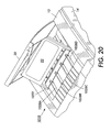
- Figure 19 shows another embodiment of a solid ink, or phase change ink printer 1010 that still includes an outer housing having a top surface 1012 and side surfaces 1014.
- a user interface display such as a front panel display screen 1016 displays information concerning the status of the printer, and user instructions.
- Buttons 1018 or other control elements may be adjacent the user interface window, or at other locations on the printer, to permit user interaction with the printer.
- the ink feed system may be contained under the top surface of the housing.
- the top surface of the housing includes a hinged top cover 20 that opens to reveal the ink feed system, as shown in Figures 19 and 20.
- the ink access cover 20 is attached to a load linkage 22 so that when the ink access cover 20 is raised, the ink load linkage 22 slides and pivots to an ink load position.
- the interaction of the ink access cover and the ink load linkage element is described in United States Patent No. 5,861,903 for an Ink Feed System, issued January 19, 1999 to Crawford et al.
- Opening the ink access cover 20 reveals a key plate 1026 having keyed openings 1024.
- the keyed openings provide access to a feed chute comprising several individual feed channels 1028. Each keyed opening provides access to an insertion end of one of the several individual feed channels 1028 of the solid ink feed system.
- a color printer typically uses four colors of ink (black, cyan, magenta, and yellow). Each color corresponds to one of the feed channels.
- the key plate has four keyed openings 1024A, 1024B, 1024C, and 1024D. Each keyed opening 1024A, 1024B, 1024C, 1024D of the key plate 1026 has a unique shape.
- the ink sticks 1030 of the color for that feed channel have a shape corresponding to the shape of the keyed opening 1024.
- the lateral sides of the key plate openings and the lateral sides of the ink sticks may have corresponding shapes.
- the keyed openings and corresponding ink stick shapes are designed to ensure that only ink sticks of the proper color are inserted into each ink stick feed channel.
- Figure 20 shows the ink access cover 20 partially open.
- each feed channel 1028 is a longitudinal feed channel designed to deliver ink sticks 1030 of a particular color to a corresponding melt plate 32.
- the third feed channel 1028C is shown in Figures 21 and 22, all the feed channels are identical for purposes of the following description.
- Each feed channel in the particular embodiment illustrated includes a push block 1034 driven by a driving force or element such as a constant force spring 1036 to push the individual ink sticks 1030 along the length of the longitudinal feed channel 28 toward the melt plates 32 that are at the melt end of each feed channel.
- Figure 22 shows the arrangement of elements when the ink access cover 20 ( Figures 19 and 20) is closed, and the spring 36 is under tension. The tension in the spring presses the push block 1034 against the last ink stick (the ink stick closest to the insertion end of the feed channel).
- the feed channel has a longitudinal dimension from the insertion end to the melt end, and a lateral dimension, substantially perpendicular to the longitudinal dimension.
- the feed channel receives ink sticks inserted at the insertion end.
- the feed channel has sufficient longitudinal length that multiple ink sticks can be inserted into the feed channel, as seen in Figure 22.
- Each feed channel delivers ink sticks along the longitudinal length or feed direction of the channel to the corresponding melt plate at the melt end of the feed channel.
- the melt end of the feed channel is adjacent the melt plate.
- the melt plate melts the solid ink stick into a liquid form.
- the melted ink 31 drips through a gap 33 between the melt end of the feed channel and the melt plate, and into a liquid ink reservoir (not shown).
- Figure 23 shows an ink stick 1030 formed of an ink stick body.
- the ink stick body may be substantially rectangular in shape, although those familiar with the art will recognize that other shapes can also be used.
- the ink stick body may be formed by pour molding, compression molding, or other formation techniques.
- Figure 23 shows one particular embodiment of an ink stick incorporating an alignment feature for enhancing the ability of ink sticks to maintain their proper alignment in the feed channel of the solid ink feed system of the printer.
- the ink stick is illustrated without the key shapes on the lateral sides that correspond to the key plate openings 1024 through the key plate 1026, to simplify the illustration.
- the particular embodiment shown includes a substantially rectangular ink stick body that has a bottom surface 1052 and a substantially parallel top surface 1054.
- a pair of lateral side surfaces 1056 connect the bottom surface 1052 and the top surface 1054.
- the lateral side surfaces 1056 need not be planar.
- the lateral side surfaces can be stepped so that the lower portion of the ink stick body is narrower than the upper portion, or the upper portion is narrower than the lower portion.
- the lateral side surfaces 1056 can be shaped to provide a keying function.
- the key shaped lateral side surfaces correspond to the lateral edges of the keyed openings in the key plate to provide a unique match between each keyed opening and the corresponding ink sticks intended for insertion through that keyed opening and into that feed channel.
- the ink stick additionally includes a first end surface 1061 and a second end surface 1062.
- the first and second end surfaces are substantially parallel to one another, and substantially perpendicular to both the top and bottom surfaces, and to the lateral side surfaces.
- the first and second end surfaces need not be necessarily parallel to one another.
- the first and second end surfaces 1061, 1062 have complementary non-planar shapes or contours that provide nesting shapes or nesting elements 1071, 1072. These contours of the end surfaces 1061, 1062 may be defined by a plurality of straight lines connecting the top surface and the bottom surface along each of the end surfaces of the ink stick body.
- the contour of the first end surface forms one or more protruding nesting elements 1071 extending from the face of the first end surface.
- the illustrated embodiment includes a pair of matching and symmetrically placed nesting elements 1071 on the lateral outer portions of the first end surface.
- the protruding nesting elements illustrated extend uniformly along the entire height of the first end surface.
- the protruding nesting elements 1071 may be segmented along the height of the first end surface, or may extend along only a portion of the height of the first end surface.
- the second end surface has recessed nesting elements 1072 that have shapes complementary to the shapes of the protruding nesting elements 1071 on the first end surface.
- the protruding nesting elements 1071 on the first end surface of one ink stick can then are capable of nesting into the recessed nesting elements 1072 of the second end surface of an adjacent ink stick when the ink sticks abut one another, such as when the ink sticks are stacked in the feed channel 1028.
- the recessed nesting elements 1072 of the contour of the second end surface 1062 of a first ink stick 1030A nest with the protruding nesting elements 1071 of the contour on the first end surface 1061 of the second ink stick 1030B.
- the lateral sides of the protruding nesting elements 1071 and recessed nesting elements 1072 closely match one another to limit movement of the ink sticks relative one another. By limiting relative movement of the ink sticks with respect to one another, the ink sticks do not become skewed with respect to each other, or with respect to the feed channel, as the ink sticks travel along the length of the feed channel of the solid ink feed system.
- the ink stick With the ink stick properly aligned with the feed channel, the ink stick meets the melt plate 32 normal to the melt plate surface. Proper alignment between the ink stick and the melt plate enhances even melting of the ink stick. Even melting reduces the formation of unmelted corner slivers at the trailing end of each ink stick. Such unmelted corner slivers may slip through the gap 33 between the melt plate and the end of the feed channel, potentially interfering with the proper functioning of certain portions of the printer (see Figures 21 and 22).
- Key element shapes (not shown) in the lateral side surfaces 1056 of the ink stick body may tend to affect the orientation of the ink stick body as the ink stick moves along the feed channel.
- the interaction of the nesting elements 1071, 1072 of the contoured end surfaces 1061, 1062 of adjacent ink sticks counteracts that tendency, and maintains the correct orientation of the ink stick in the feed channel.
- the nesting of the protruding nesting elements 1071 and the recessed nesting elements 1072 of adjacent ink sticks reduce the "steering" effect of the push block 1034 acting on the trailing end surface of the ink stick in the feed channel 1028.
- laterally offset pressure by the pusher block is of lesser concern, and maintaining a perfect lateral balance of the force exerted by the push block on the ink stick is less critical than with certain other designs.
- the ink sticks can be placed in the feed channel 1028 with either the first end surface 61 as the leading end surface (meeting the melt plate 32 first), or the second end surface 1062 as the leading end surface.
- the perimeter of the keyed openings 1024 can be formed to match the protruding and recessed nesting elements 1071, 1072 of the ink sticks. So matching the keyed openings with the nesting elements provides ink stick orientation control to ensure the printer operator consistently inserts the ink sticks in the correct direction.
- ink sticks 1130 incorporating contoured first and second end surfaces 1161, 1162 is shown.
- the ink sticks are shown inserted in the feed channel to illustrate the nesting of a single central recessed nesting element 1172 on the second end surface 1162 of one ink stick 1130A nests with a protruding nesting element 1171 on the first end surface 1162 of the adjacent ink stick 1130B.
- the contour of the front and rear end surfaces are each formed by a plurality of substantially parallel straight lines connecting the top surface and the bottom surface along the front and end surfaces respectively, so that the protruding and recessed nesting elements 1171, 1172 extend along the entire height of the end surfaces 1161, 1162.
- Figure 27 illustrates an embodiment of the ink stick in which the protruding nesting element 1571 does not extend along the entire height of the end surface 1561 of the ink stick body.
- the protruding nesting element illustrated extends along the upper portion of the end surface 1561.
- the protruding nesting element can extend along the lower portion of the end surface as well.
- the corresponding recessed nesting element 1572 extends along at least the same portion of the height of the second end surface 1562 as the protruding nesting element extends on the first end surface 1561.
- the recessed nesting element can extend along a greater portion of the height of the second end surface than does the protruding nesting element.
- Figure 28 illustrates an embodiment of the ink stick in which the first and second end surfaces 1461, 1462 are each stepped or segmented.
- the protruding nesting element 1471 extends along at least a segment 1461A of the first end surface.
- a corresponding recessed nesting element 1472 extends along a corresponding portion of a segment 1462A of the second end surface.
- the end surfaces 1461, 1462 are each formed with an outermost portion above an inner portion.
- the protruding and recessed nesting elements are formed in the outermost segments of the first and second end surfaces. Numerous other arrangements providing segmented end surfaces for the ink stick can also be used.
- the protruding and recessed nesting elements need not both be in the outermost segments of both end surfaces.
- the protruding and recessed nesting elements can be formed in other segments of the end surfaces that mate with one another when the ink sticks are placed adjacent one another, as in an ink feed channel.
- Figure 29 illustrates that the nesting elements may assume a variety of shapes.
- the shape of the protruding nesting element 1271 on one end surface 1261 substantially corresponds to and is the complement of the shape of the recessed nesting element 1272 on the other end surface.
- Such complementary shaping maximizes the nesting capability, reducing relative movement of the ink sticks with respect to one another.
- FIG. 30 and 31 illustrates that the contours of the first and second end surfaces 1361, 1362 could be formed of curved lines extending from the top of the ink stick to the bottom of the ink stick.
- the protruding nesting element 1371 from the first end surface 1361 of the ink stick does not extend along the entire height of the first end surface from the top surface to the bottom surface.
- the recessed nesting element 1372 in the second end surface 1362 can, but need not, extend along the entire height of the second end surface.
- the recessed nesting element 1372 is at least as large as the protruding nesting element 1371 so that the recessed nesting element can received the protruding nesting element of an adjacent ink stick.
- the recessed nesting element 1372 has a position relative to the side surfaces 1356 and to the bottom surface 1352 of the ink stick body that corresponds with the position of the protruding nesting element 1371.
- the bottom surfaces of the adjacent ink sticks are substantially aligned, and the side surfaces of the adjacent ink sticks are also substantially aligned.
- the lateral dimensions of the recessed and projecting nesting elements are substantially identical, so that the interacting nesting elements block significant movement of the ink sticks relative to one another.
- the ink stick 1030 is formed of two sections 1031A, 1031B that fit together at a joining line 1035.
- the joining line is a substantially vertical cut through the ink stick body between the top and bottom surfaces 1054, 1052.
- the joining line of the illustrated embodiment intersects the lateral side surfaces 1056 of the ink stick body, dividing the ink stick into longitudinal sections.
- the first longitudinal section 1031A of the ink stick contains the first end surface 1061 of the ink stick body, along with its protruding nesting element 1071.
- the second longitudinal section 1031B of the ink stick contains the second end surface 1062 of the ink stick body, along with the recessed nesting element 1072.
- Each section of the ink stick has a perimeter that includes a joint perimeter segment.
- the joint perimeter segments of the two ink stick sections 1031A, 1031B have complementary shapes. When the two ink stick sections are brought together with the joint perimeter segments abutting, they form the joining line 1035.
- the illustrated joining line 1035 has a "puzzle cut" shape that provides a protrusion from one section of the ink stick that fits into a recess in the other section. The interaction of such a protrusion and recess helps to hold the two sections of the ink stick together as the printer operator inserts the assembled ink stick through the key plate opening 1024 into the feed channel.
- the illustrated sections of the ink stick are substantially equal in size. However, other embodiments can have ink stick sections that are dissimilar in size. In addition, the ink stick can include more than two sections.
- the joining line can alternatively extend top to bottom, diagonally across the ink stick body, or longitudinally along the ink stick body, so that the joining line intersects the end surfaces 1061, 1062 of the ink stick body and divides the ink stick into lateral sections.
- the joining line is longitudinal in the ink stick body, dividing the ink stick body into lateral sections, more than one section of the ink stick body can contain some aspects of the protruding nesting element 1071, and more than one section of the ink stick body can contain some aspects of the recessed nesting element 1072.
- one or more sections of the ink stick body can contain at least portions of both the protruding nesting element 1071 and the recessed nesting element 1072.
- the shapes of the ink sticks including the shapes and configurations of the nesting elements, without departing from the spirit of the present invention.
- different numbers of nesting elements can be included on the end surfaces of the ink sticks.
- the ink sticks can have non-cubic shapes.
- the nesting elements need not constrain vertical movement of the ink sticks relative one another.
- a substantial portion, or all, of the end surfaces of the ink sticks can be used to provide the nesting shapes for the ink sticks. Therefore, the following claims are not limited to the specific embodiments described and shown above.
Applications Claiming Priority (2)
| Application Number | Priority Date | Filing Date | Title |
|---|---|---|---|
| US135105 | 2002-04-29 | ||
| US10/135,105 US6672716B2 (en) | 2002-04-29 | 2002-04-29 | Multiple portion solid ink stick |
Publications (2)
| Publication Number | Publication Date |
|---|---|
| EP1359017A1 true EP1359017A1 (fr) | 2003-11-05 |
| EP1359017B1 EP1359017B1 (fr) | 2006-01-18 |
Family
ID=29215643
Family Applications (1)
| Application Number | Title | Priority Date | Filing Date |
|---|---|---|---|
| EP03008881A Expired - Fee Related EP1359017B1 (fr) | 2002-04-29 | 2003-04-29 | Bâton d'encre solide à plusieurs portions |
Country Status (5)
| Country | Link |
|---|---|
| US (1) | US6672716B2 (fr) |
| EP (1) | EP1359017B1 (fr) |
| JP (1) | JP2003312015A (fr) |
| BR (1) | BR0301301A (fr) |
| DE (1) | DE60303236T2 (fr) |
Cited By (3)
| Publication number | Priority date | Publication date | Assignee | Title |
|---|---|---|---|---|
| EP1366912A2 (fr) | 2002-05-30 | 2003-12-03 | Xerox Corporation | Appareil de chargement et d'alimentation en encre solide |
| EP1366918A3 (fr) * | 2002-05-30 | 2004-08-18 | Xerox Corporation | Appareil de chargement et d'alimentation en encre solide |
| CN101264693B (zh) * | 2007-03-12 | 2012-09-19 | 施乐公司 | 具有倾斜表面的固体墨棒、墨棒组以及供应墨棒的方法 |
Families Citing this family (26)
| Publication number | Priority date | Publication date | Assignee | Title |
|---|---|---|---|---|
| US6722764B2 (en) * | 2002-04-29 | 2004-04-20 | Xerox Corporation | Feed guidance and identification for ink stick |
| US7503648B2 (en) * | 2005-06-09 | 2009-03-17 | Xerox Corporation | Ink consumption determination |
| US7874661B2 (en) * | 2006-06-22 | 2011-01-25 | Xerox Corporation | Solid ink stick with coded markings and method and apparatus for reading markings |
| US7553008B2 (en) * | 2006-06-23 | 2009-06-30 | Xerox Corporation | Ink loader for interfacing with solid ink sticks |
| US7857439B2 (en) * | 2006-06-23 | 2010-12-28 | Xerox Corporation | Solid ink stick with interface element |
| US7753509B2 (en) * | 2006-08-14 | 2010-07-13 | Xerox Corporation | Segmented ink stick |
| US7810918B2 (en) * | 2006-11-07 | 2010-10-12 | Xerox Corporation | One way compatibility keying for solid ink sticks |
| US7854501B2 (en) * | 2006-11-07 | 2010-12-21 | Xerox Corporation | Common side insertion keying for phase change ink sticks |
| US7780283B2 (en) * | 2006-11-07 | 2010-08-24 | Xerox Corporation | Independent keying and guidance for solid ink sticks |
| US7883195B2 (en) * | 2006-11-21 | 2011-02-08 | Xerox Corporation | Solid ink stick features for printer ink transport and method |
| US7794072B2 (en) | 2006-11-21 | 2010-09-14 | Xerox Corporation | Guide for printer solid ink transport and method |
| US7976144B2 (en) | 2006-11-21 | 2011-07-12 | Xerox Corporation | System and method for delivering solid ink sticks to a melting device through a non-linear guide |
| US7798624B2 (en) | 2006-11-21 | 2010-09-21 | Xerox Corporation | Transport system for solid ink in a printer |
| US7819513B2 (en) * | 2007-03-09 | 2010-10-26 | Xerox Corporation | Solid ink stick with multiple axis interlocking |
| US8016403B2 (en) | 2007-10-03 | 2011-09-13 | Xerox Corporation | Solid ink stick with visual orientation indicator |
| US7976118B2 (en) * | 2007-10-22 | 2011-07-12 | Xerox Corporation | Transport system for providing a continuous supply of solid ink to a melting assembly in a printer |
| US7891792B2 (en) * | 2007-11-06 | 2011-02-22 | Xerox Corporation | Solid ink stick with transition indicating region |
| US7942515B2 (en) | 2007-12-21 | 2011-05-17 | Xerox Corporation | Solid ink stick having a feed drive coupler |
| US7887173B2 (en) | 2008-01-18 | 2011-02-15 | Xerox Corporation | Transport system having multiple moving forces for solid ink delivery in a printer |
| US8240830B2 (en) | 2010-03-10 | 2012-08-14 | Xerox Corporation | No spill, feed controlled removable container for delivering pelletized substances |
| US8366255B2 (en) * | 2010-06-02 | 2013-02-05 | Xerox Corporation | Solid ink stick with retrieval feature |
| US8814336B2 (en) | 2011-12-22 | 2014-08-26 | Xerox Corporation | Solid ink stick configuration |
| US8646892B2 (en) | 2011-12-22 | 2014-02-11 | Xerox Corporation | Solid ink stick delivery apparatus using a lead screw drive |
| US8777386B2 (en) | 2012-10-17 | 2014-07-15 | Xerox Corporation | Solid ink stick having identical identifying features on a plurality of edges |
| US8727478B2 (en) | 2012-10-17 | 2014-05-20 | Xerox Corporation | Ink loader having optical sensors to identify solid ink sticks |
| CA3133635A1 (fr) | 2021-01-29 | 2022-07-29 | Quanta Associates, L.P. | Collier de masse a ressort |
Citations (3)
| Publication number | Priority date | Publication date | Assignee | Title |
|---|---|---|---|---|
| US5442387A (en) * | 1991-06-17 | 1995-08-15 | Tektronix, Inc. | Apparatus for supplying phase change ink to an ink jet printer |
| EP0703085A2 (fr) * | 1994-09-20 | 1996-03-27 | Tektronix, Inc. | Bâton d'encre solide |
| US5734402A (en) * | 1996-03-07 | 1998-03-31 | Tekronix, Inc. | Solid ink stick feed system |
Family Cites Families (102)
| Publication number | Priority date | Publication date | Assignee | Title |
|---|---|---|---|---|
| US3205485A (en) * | 1960-10-21 | 1965-09-07 | Ti Group Services Ltd | Screening vane electro-mechanical transducer |
| US3229198A (en) * | 1962-09-28 | 1966-01-11 | Hugo L Libby | Eddy current nondestructive testing device for measuring multiple parameter variables of a metal sample |
| US4302721A (en) * | 1978-05-08 | 1981-11-24 | Tencor Instruments | Non-contacting resistivity instrument with structurally related conductance and distance measuring transducers |
| FR2589566A1 (fr) * | 1985-11-06 | 1987-05-07 | Cegedur | Procede de mesure au defile et sans contact de l'epaisseur et de la temperature de feuilles metalliques minces au moyen de courants de foucault |
| US4750141A (en) * | 1985-11-26 | 1988-06-07 | Ade Corporation | Method and apparatus for separating fixture-induced error from measured object characteristics and for compensating the measured object characteristic with the error, and a bow/warp station implementing same |
| US4938600A (en) * | 1989-02-09 | 1990-07-03 | Interactive Video Systems, Inc. | Method and apparatus for measuring registration between layers of a semiconductor wafer |
| US5485082A (en) * | 1990-04-11 | 1996-01-16 | Micro-Epsilon Messtechnik Gmbh & Co. Kg | Method of calibrating a thickness measuring device and device for measuring or monitoring the thickness of layers, tapes, foils, and the like |
| US5455604A (en) | 1991-04-29 | 1995-10-03 | Tektronix, Inc. | Ink jet printer architecture and method |
| US5283141A (en) * | 1992-03-05 | 1994-02-01 | National Semiconductor | Photolithography control system and method using latent image measurements |
| US5857258A (en) * | 1992-03-13 | 1999-01-12 | The United States Of America As Represented By The Secretary Of Commerce | Electrical test structure and method for measuring the relative locations of conductive features on an insulating substrate |
| US5602492A (en) * | 1992-03-13 | 1997-02-11 | The United States Of America As Represented By The Secretary Of Commerce | Electrical test structure and method for measuring the relative locations of conducting features on an insulating substrate |
| USD346821S (en) * | 1992-07-27 | 1994-05-10 | Dataproducts Corporation | Stepped diameter recessed solid ink pellet |
| USD335683S (en) * | 1992-07-27 | 1993-05-18 | Dataproducts Corporation | Smooth edge recessed solid ink pellet |
| US5823853A (en) * | 1996-07-18 | 1998-10-20 | Speedfam Corporation | Apparatus for the in-process detection of workpieces with a monochromatic light source |
| US5805191A (en) | 1992-11-25 | 1998-09-08 | Tektronix, Inc. | Intermediate transfer surface application system |
| US5642296A (en) * | 1993-07-29 | 1997-06-24 | Texas Instruments Incorporated | Method of diagnosing malfunctions in semiconductor manufacturing equipment |
| JP3039210B2 (ja) * | 1993-08-03 | 2000-05-08 | 日本電気株式会社 | 半導体装置の製造方法 |
| US5700180A (en) * | 1993-08-25 | 1997-12-23 | Micron Technology, Inc. | System for real-time control of semiconductor wafer polishing |
| US5546312A (en) * | 1993-09-20 | 1996-08-13 | Texas Instruments Incorporated | Use of spatial models for simultaneous control of various non-uniformity metrics |
| DE69425100T2 (de) * | 1993-09-30 | 2001-03-15 | Koninkl Philips Electronics Nv | Dynamisches neuronales Netzwerk |
| US5497381A (en) * | 1993-10-15 | 1996-03-05 | Analog Devices, Inc. | Bitstream defect analysis method for integrated circuits |
| US5526293A (en) * | 1993-12-17 | 1996-06-11 | Texas Instruments Inc. | System and method for controlling semiconductor wafer processing |
| JPH07201946A (ja) * | 1993-12-28 | 1995-08-04 | Hitachi Ltd | 半導体装置等の製造方法及びその装置並びに検査方法及びその装置 |
| US5511005A (en) * | 1994-02-16 | 1996-04-23 | Ade Corporation | Wafer handling and processing system |
| US5666297A (en) * | 1994-05-13 | 1997-09-09 | Aspen Technology, Inc. | Plant simulation and optimization software apparatus and method using dual execution models |
| JP3402412B2 (ja) * | 1994-09-20 | 2003-05-06 | 株式会社リコー | プロセスシミュレーション入力データ設定装置 |
| US5519605A (en) * | 1994-10-24 | 1996-05-21 | Olin Corporation | Model predictive control apparatus and method |
| DE4446966A1 (de) * | 1994-12-28 | 1996-07-04 | Itt Ind Gmbh Deutsche | Informationssystem zur Produktionskontrolle |
| US5617023A (en) * | 1995-02-02 | 1997-04-01 | Otis Elevator Company | Industrial contactless position sensor |
| US5646870A (en) * | 1995-02-13 | 1997-07-08 | Advanced Micro Devices, Inc. | Method for setting and adjusting process parameters to maintain acceptable critical dimensions across each die of mass-produced semiconductor wafers |
| US5541510A (en) * | 1995-04-06 | 1996-07-30 | Kaman Instrumentation Corporation | Multi-Parameter eddy current measuring system with parameter compensation technical field |
| US5559428A (en) * | 1995-04-10 | 1996-09-24 | International Business Machines Corporation | In-situ monitoring of the change in thickness of films |
| USD373139S (en) * | 1995-05-11 | 1996-08-27 | Tektronix, Inc. | Solid ink stick for a color printer |
| USD372270S (en) * | 1995-05-11 | 1996-07-30 | Tektronix, Inc. | Solid ink stick for a color printer |
| US5649169A (en) * | 1995-06-20 | 1997-07-15 | Advanced Micro Devices, Inc. | Method and system for declustering semiconductor defect data |
| US5665199A (en) * | 1995-06-23 | 1997-09-09 | Advanced Micro Devices, Inc. | Methodology for developing product-specific interlayer dielectric polish processes |
| US5825913A (en) * | 1995-07-18 | 1998-10-20 | Cognex Corporation | System for finding the orientation of a wafer |
| US6036349A (en) * | 1995-07-27 | 2000-03-14 | Health Designs, Inc. | Method and apparatus for validation of model-based predictions |
| US5777901A (en) * | 1995-09-29 | 1998-07-07 | Advanced Micro Devices, Inc. | Method and system for automated die yield prediction in semiconductor manufacturing |
| US5761064A (en) * | 1995-10-06 | 1998-06-02 | Advanced Micro Devices, Inc. | Defect management system for productivity and yield improvement |
| US5654903A (en) * | 1995-11-07 | 1997-08-05 | Lucent Technologies Inc. | Method and apparatus for real time monitoring of wafer attributes in a plasma etch process |
| US5719796A (en) * | 1995-12-04 | 1998-02-17 | Advanced Micro Devices, Inc. | System for monitoring and analyzing manufacturing processes using statistical simulation with single step feedback |
| US5674787A (en) * | 1996-01-16 | 1997-10-07 | Sematech, Inc. | Selective electroless copper deposited interconnect plugs for ULSI applications |
| US5861903A (en) | 1996-03-07 | 1999-01-19 | Tektronix, Inc. | Ink feed system |
| US6017143A (en) * | 1996-03-28 | 2000-01-25 | Rosemount Inc. | Device in a process system for detecting events |
| WO1997036164A1 (fr) * | 1996-03-28 | 1997-10-02 | Bio-Analytics, Inc., Doing Business As Biomedware | Technique de mesure du degre d'association de donnees dont les dimensions sont referencees |
| US5735055A (en) * | 1996-04-23 | 1998-04-07 | Aluminum Company Of America | Method and apparatus for measuring the thickness of an article at a plurality of points |
| US5663797A (en) * | 1996-05-16 | 1997-09-02 | Micron Technology, Inc. | Method and apparatus for detecting the endpoint in chemical-mechanical polishing of semiconductor wafers |
| US5910846A (en) * | 1996-05-16 | 1999-06-08 | Micron Technology, Inc. | Method and apparatus for detecting the endpoint in chemical-mechanical polishing of semiconductor wafers |
| US5960185A (en) * | 1996-06-24 | 1999-09-28 | International Business Machines Corporation | Method and apparatus for wafer disposition based on systematic error modeling |
| US6053608A (en) * | 1996-07-24 | 2000-04-25 | Brother Kogyo Kabushiki Kaisha | Ink pellet with step configuration including slidable bearing surfaces |
| US6246972B1 (en) * | 1996-08-23 | 2001-06-12 | Aspen Technology, Inc. | Analyzer for modeling and optimizing maintenance operations |
| US5667424A (en) * | 1996-09-25 | 1997-09-16 | Chartered Semiconductor Manufacturing Pte Ltd. | New chemical mechanical planarization (CMP) end point detection apparatus |
| TW364956B (en) * | 1996-10-21 | 1999-07-21 | Nxp Bv | Method and system for assessing a measurement procedure and measurement-induced uncertainties on a batchwise manufacturing process of discrete products |
| US6064759A (en) * | 1996-11-08 | 2000-05-16 | Buckley; B. Shawn | Computer aided inspection machine |
| USD403699S (en) * | 1997-03-10 | 1999-01-05 | Tektronix, Inc. | Solid ink stick for a color printer |
| US6108091A (en) * | 1997-05-28 | 2000-08-22 | Lam Research Corporation | Method and apparatus for in-situ monitoring of thickness during chemical-mechanical polishing |
| US6097887A (en) * | 1997-10-27 | 2000-08-01 | Kla-Tencor Corporation | Software system and method for graphically building customized recipe flowcharts |
| US5985497A (en) * | 1998-02-03 | 1999-11-16 | Advanced Micro Devices, Inc. | Method for reducing defects in a semiconductor lithographic process |
| US6455937B1 (en) * | 1998-03-20 | 2002-09-24 | James A. Cunningham | Arrangement and method for improved downward scaling of higher conductivity metal-based interconnects |
| US6017771A (en) * | 1998-04-27 | 2000-01-25 | Taiwan Semiconductor Manufacturing Company, Ltd. | Method and system for yield loss analysis by yield management system |
| US6395152B1 (en) * | 1998-07-09 | 2002-05-28 | Acm Research, Inc. | Methods and apparatus for electropolishing metal interconnections on semiconductor devices |
| US6127263A (en) * | 1998-07-10 | 2000-10-03 | Applied Materials, Inc. | Misalignment tolerant techniques for dual damascene fabrication |
| US6141660A (en) * | 1998-07-16 | 2000-10-31 | International Business Machines Corporation | Command line interface for creating business objects for accessing a hierarchical database |
| US6169931B1 (en) * | 1998-07-29 | 2001-01-02 | Southwest Research Institute | Method and system for modeling, predicting and optimizing chemical mechanical polishing pad wear and extending pad life |
| US6210983B1 (en) * | 1998-10-21 | 2001-04-03 | Texas Instruments Incorporated | Method for analyzing probe yield sensitivities to IC design |
| US6280289B1 (en) * | 1998-11-02 | 2001-08-28 | Applied Materials, Inc. | Method and apparatus for detecting an end-point in chemical mechanical polishing of metal layers |
| US6173240B1 (en) * | 1998-11-02 | 2001-01-09 | Ise Integrated Systems Engineering Ag | Multidimensional uncertainty analysis |
| US6214734B1 (en) * | 1998-11-20 | 2001-04-10 | Vlsi Technology, Inc. | Method of using films having optimized optical properties for chemical mechanical polishing endpoint detection |
| US6172756B1 (en) * | 1998-12-11 | 2001-01-09 | Filmetrics, Inc. | Rapid and accurate end point detection in a noisy environment |
| US6136163A (en) * | 1999-03-05 | 2000-10-24 | Applied Materials, Inc. | Apparatus for electro-chemical deposition with thermal anneal chamber |
| US7020537B2 (en) * | 1999-04-13 | 2006-03-28 | Semitool, Inc. | Tuning electrodes used in a reactor for electrochemically processing a microelectronic workpiece |
| US6334807B1 (en) * | 1999-04-30 | 2002-01-01 | International Business Machines Corporation | Chemical mechanical polishing in-situ end point system |
| US6360133B1 (en) * | 1999-06-17 | 2002-03-19 | Advanced Micro Devices, Inc. | Method and apparatus for automatic routing for reentrant process |
| US6204165B1 (en) * | 1999-06-24 | 2001-03-20 | International Business Machines Corporation | Practical air dielectric interconnections by post-processing standard CMOS wafers |
| EP1065567A3 (fr) * | 1999-06-29 | 2001-05-16 | Applied Materials, Inc. | Contrôle intégré d' une dimension critique |
| US20030213772A9 (en) * | 1999-07-09 | 2003-11-20 | Mok Yeuk-Fai Edwin | Integrated semiconductor substrate bevel cleaning apparatus and method |
| US6368883B1 (en) * | 1999-08-10 | 2002-04-09 | Advanced Micro Devices, Inc. | Method for identifying and controlling impact of ambient conditions on photolithography processes |
| US6405096B1 (en) * | 1999-08-10 | 2002-06-11 | Advanced Micro Devices, Inc. | Method and apparatus for run-to-run controlling of overlay registration |
| US6217412B1 (en) * | 1999-08-11 | 2001-04-17 | Advanced Micro Devices, Inc. | Method for characterizing polish pad lots to eliminate or reduce tool requalification after changing a polishing pad |
| US6287879B1 (en) * | 1999-08-11 | 2001-09-11 | Micron Technology, Inc. | Endpoint stabilization for polishing process |
| US6276989B1 (en) * | 1999-08-11 | 2001-08-21 | Advanced Micro Devices, Inc. | Method and apparatus for controlling within-wafer uniformity in chemical mechanical polishing |
| US6284622B1 (en) * | 1999-10-25 | 2001-09-04 | Advanced Micro Devices, Inc. | Method for filling trenches |
| IL133326A0 (en) * | 1999-12-06 | 2001-04-30 | Nova Measuring Instr Ltd | Method and system for endpoint detection |
| US6405144B1 (en) * | 2000-01-18 | 2002-06-11 | Advanced Micro Devices, Inc. | Method and apparatus for programmed latency for improving wafer-to-wafer uniformity |
| US6584369B2 (en) * | 2000-02-02 | 2003-06-24 | Texas Instruments Incorporated | Method and system for dispatching semiconductor lots to manufacturing equipment for fabrication |
| US7059948B2 (en) * | 2000-12-22 | 2006-06-13 | Applied Materials | Articles for polishing semiconductor substrates |
| JP3979791B2 (ja) * | 2000-03-08 | 2007-09-19 | 株式会社ルネサステクノロジ | 半導体装置およびその製造方法 |
| US6290572B1 (en) * | 2000-03-23 | 2001-09-18 | Micron Technology, Inc. | Devices and methods for in-situ control of mechanical or chemical-mechanical planarization of microelectronic-device substrate assemblies |
| US6368884B1 (en) * | 2000-04-13 | 2002-04-09 | Advanced Micro Devices, Inc. | Die-based in-fab process monitoring and analysis system for semiconductor processing |
| US6435952B1 (en) * | 2000-06-30 | 2002-08-20 | Lam Research Corporation | Apparatus and method for qualifying a chemical mechanical planarization process |
| WO2002004887A1 (fr) * | 2000-07-08 | 2002-01-17 | Semitool, Inc. | Procedes et appareil de traitement microelectronique de pieces a usiner au moyen de la metrologie |
| US6379980B1 (en) * | 2000-07-26 | 2002-04-30 | Advanced Micro Devices, Inc. | Method and apparatus for monitoring material removal tool performance using endpoint time removal rate determination |
| US6307628B1 (en) * | 2000-08-18 | 2001-10-23 | Taiwan Semiconductor Manufacturing Company, Ltd | Method and apparatus for CMP end point detection using confocal optics |
| US6593737B2 (en) * | 2000-08-24 | 2003-07-15 | Shell Oil Company | Method for measuring the wall thickness of an electrically conductive object |
| JP2002093761A (ja) * | 2000-09-19 | 2002-03-29 | Sony Corp | 研磨方法、研磨装置、メッキ方法およびメッキ装置 |
| KR100366630B1 (ko) * | 2000-09-20 | 2003-01-09 | 삼성전자 주식회사 | 샘플 스킵 방식의 알고리즘을 이용한 웨이퍼의 연마 시간제어 방법 및 이를 이용한 웨이퍼의 연마 방법 |
| JP2002124496A (ja) * | 2000-10-18 | 2002-04-26 | Hitachi Ltd | 研磨加工の終点検出計測方法及びその装置、並びにそれを用いた半導体デバイスの製造方法及びその製造装置 |
| US6304999B1 (en) * | 2000-10-23 | 2001-10-16 | Advanced Micro Devices, Inc. | Method and apparatus for embedded process control framework in tool systems |
| US6517413B1 (en) * | 2000-10-25 | 2003-02-11 | Taiwan Semiconductor Manufacturing Company | Method for a copper CMP endpoint detection system |
| US6336841B1 (en) * | 2001-03-29 | 2002-01-08 | Macronix International Co. Ltd. | Method of CMP endpoint detection |
| US6549279B2 (en) * | 2001-04-09 | 2003-04-15 | Speedfam-Ipec Corporation | Method and apparatus for optical endpoint calibration in CMP |
-
2002
- 2002-04-29 US US10/135,105 patent/US6672716B2/en not_active Expired - Lifetime
-
2003
- 2003-04-28 BR BR0301301-4A patent/BR0301301A/pt not_active Application Discontinuation
- 2003-04-29 EP EP03008881A patent/EP1359017B1/fr not_active Expired - Fee Related
- 2003-04-29 DE DE60303236T patent/DE60303236T2/de not_active Expired - Lifetime
- 2003-04-30 JP JP2003124782A patent/JP2003312015A/ja not_active Withdrawn
Patent Citations (3)
| Publication number | Priority date | Publication date | Assignee | Title |
|---|---|---|---|---|
| US5442387A (en) * | 1991-06-17 | 1995-08-15 | Tektronix, Inc. | Apparatus for supplying phase change ink to an ink jet printer |
| EP0703085A2 (fr) * | 1994-09-20 | 1996-03-27 | Tektronix, Inc. | Bâton d'encre solide |
| US5734402A (en) * | 1996-03-07 | 1998-03-31 | Tekronix, Inc. | Solid ink stick feed system |
Cited By (4)
| Publication number | Priority date | Publication date | Assignee | Title |
|---|---|---|---|---|
| EP1366912A2 (fr) | 2002-05-30 | 2003-12-03 | Xerox Corporation | Appareil de chargement et d'alimentation en encre solide |
| EP1366912A3 (fr) * | 2002-05-30 | 2004-08-18 | Xerox Corporation | Appareil de chargement et d'alimentation en encre solide |
| EP1366918A3 (fr) * | 2002-05-30 | 2004-08-18 | Xerox Corporation | Appareil de chargement et d'alimentation en encre solide |
| CN101264693B (zh) * | 2007-03-12 | 2012-09-19 | 施乐公司 | 具有倾斜表面的固体墨棒、墨棒组以及供应墨棒的方法 |
Also Published As
| Publication number | Publication date |
|---|---|
| DE60303236D1 (de) | 2006-04-06 |
| US6672716B2 (en) | 2004-01-06 |
| JP2003312015A (ja) | 2003-11-06 |
| US20030202070A1 (en) | 2003-10-30 |
| BR0301301A (pt) | 2004-08-17 |
| EP1359017B1 (fr) | 2006-01-18 |
| DE60303236T2 (de) | 2006-07-20 |
Similar Documents
| Publication | Publication Date | Title |
|---|---|---|
| EP1359017B1 (fr) | Bâton d'encre solide à plusieurs portions | |
| EP1359020B1 (fr) | Bâton d'encre solide ayant la forme d'un signe numérique | |
| EP1359018B1 (fr) | Eléments d'identification pour assortiment de bâtons d'encre solide | |
| EP1359015A1 (fr) | Bâton d'encre solide avec un efficace rapport longueur/largeur | |
| US6986570B2 (en) | Feed guidance and identification for ink stick | |
| EP1359014B1 (fr) | Dispositif d'alignement pour bâtons d'encre solide | |
| EP1359023A1 (fr) | Codage à plusieurs segments pour l'alimentation de bâtons d'encre solide | |
| EP1366909B1 (fr) | Caractéristique de codage pour bâton d'encre solide | |
| EP1359019B1 (fr) | Canal d'alimentation codé pour l'alimentation de bâtons d'encre solide | |
| KR101336675B1 (ko) | 경사면을 구비한 고형 잉크 스틱 | |
| EP1359021A1 (fr) | Guide pour l'alimentation de bâtons d'encre solide | |
| EP1369243B1 (fr) | Clavetage du cannal pour insertion d'un bâton d'incre solide |
Legal Events
| Date | Code | Title | Description |
|---|---|---|---|
| PUAI | Public reference made under article 153(3) epc to a published international application that has entered the european phase |
Free format text: ORIGINAL CODE: 0009012 |
|
| AK | Designated contracting states |
Kind code of ref document: A1 Designated state(s): AT BE BG CH CY CZ DE DK EE ES FI FR GB GR HU IE IT LI LU MC NL PT RO SE SI SK TR |
|
| AX | Request for extension of the european patent |
Extension state: AL LT LV MK |
|
| 17P | Request for examination filed |
Effective date: 20040506 |
|
| AKX | Designation fees paid |
Designated state(s): DE FR GB |
|
| 17Q | First examination report despatched |
Effective date: 20041015 |
|
| GRAP | Despatch of communication of intention to grant a patent |
Free format text: ORIGINAL CODE: EPIDOSNIGR1 |
|
| GRAS | Grant fee paid |
Free format text: ORIGINAL CODE: EPIDOSNIGR3 |
|
| GRAA | (expected) grant |
Free format text: ORIGINAL CODE: 0009210 |
|
| AK | Designated contracting states |
Kind code of ref document: B1 Designated state(s): DE FR GB |
|
| REG | Reference to a national code |
Ref country code: GB Ref legal event code: FG4D |
|
| REF | Corresponds to: |
Ref document number: 60303236 Country of ref document: DE Date of ref document: 20060406 Kind code of ref document: P |
|
| ET | Fr: translation filed | ||
| PLBE | No opposition filed within time limit |
Free format text: ORIGINAL CODE: 0009261 |
|
| STAA | Information on the status of an ep patent application or granted ep patent |
Free format text: STATUS: NO OPPOSITION FILED WITHIN TIME LIMIT |
|
| 26N | No opposition filed |
Effective date: 20061019 |
|
| REG | Reference to a national code |
Ref country code: FR Ref legal event code: PLFP Year of fee payment: 14 |
|
| REG | Reference to a national code |
Ref country code: FR Ref legal event code: PLFP Year of fee payment: 15 |
|
| PGFP | Annual fee paid to national office [announced via postgrant information from national office to epo] |
Ref country code: FR Payment date: 20170322 Year of fee payment: 15 |
|
| PGFP | Annual fee paid to national office [announced via postgrant information from national office to epo] |
Ref country code: GB Payment date: 20180321 Year of fee payment: 16 |
|
| PGFP | Annual fee paid to national office [announced via postgrant information from national office to epo] |
Ref country code: DE Payment date: 20180320 Year of fee payment: 16 |
|
| PG25 | Lapsed in a contracting state [announced via postgrant information from national office to epo] |
Ref country code: FR Free format text: LAPSE BECAUSE OF NON-PAYMENT OF DUE FEES Effective date: 20180430 |
|
| REG | Reference to a national code |
Ref country code: DE Ref legal event code: R119 Ref document number: 60303236 Country of ref document: DE |
|
| GBPC | Gb: european patent ceased through non-payment of renewal fee |
Effective date: 20190429 |
|
| PG25 | Lapsed in a contracting state [announced via postgrant information from national office to epo] |
Ref country code: DE Free format text: LAPSE BECAUSE OF NON-PAYMENT OF DUE FEES Effective date: 20191101 Ref country code: GB Free format text: LAPSE BECAUSE OF NON-PAYMENT OF DUE FEES Effective date: 20190429 |