EP1358862A2 - Orthesis - Google Patents
Orthesis Download PDFInfo
- Publication number
- EP1358862A2 EP1358862A2 EP03009209A EP03009209A EP1358862A2 EP 1358862 A2 EP1358862 A2 EP 1358862A2 EP 03009209 A EP03009209 A EP 03009209A EP 03009209 A EP03009209 A EP 03009209A EP 1358862 A2 EP1358862 A2 EP 1358862A2
- Authority
- EP
- European Patent Office
- Prior art keywords
- orthosis
- rails
- pins
- angular range
- orthotic joint
- Prior art date
- Legal status (The legal status is an assumption and is not a legal conclusion. Google has not performed a legal analysis and makes no representation as to the accuracy of the status listed.)
- Granted
Links
- 210000003127 knee Anatomy 0.000 claims description 8
- 230000006835 compression Effects 0.000 claims description 2
- 238000007906 compression Methods 0.000 claims description 2
- 210000000629 knee joint Anatomy 0.000 abstract 1
- 210000002414 leg Anatomy 0.000 abstract 1
- 230000000694 effects Effects 0.000 description 3
- 230000003993 interaction Effects 0.000 description 2
- 210000003041 ligament Anatomy 0.000 description 2
- 210000000689 upper leg Anatomy 0.000 description 2
- 238000005452 bending Methods 0.000 description 1
- 238000011161 development Methods 0.000 description 1
- 230000018109 developmental process Effects 0.000 description 1
- 239000002184 metal Substances 0.000 description 1
- 229920003052 natural elastomer Polymers 0.000 description 1
- 229920001194 natural rubber Polymers 0.000 description 1
- 230000007935 neutral effect Effects 0.000 description 1
- 229920003051 synthetic elastomer Polymers 0.000 description 1
Images

Classifications
-
- A—HUMAN NECESSITIES
- A61—MEDICAL OR VETERINARY SCIENCE; HYGIENE
- A61F—FILTERS IMPLANTABLE INTO BLOOD VESSELS; PROSTHESES; DEVICES PROVIDING PATENCY TO, OR PREVENTING COLLAPSING OF, TUBULAR STRUCTURES OF THE BODY, e.g. STENTS; ORTHOPAEDIC, NURSING OR CONTRACEPTIVE DEVICES; FOMENTATION; TREATMENT OR PROTECTION OF EYES OR EARS; BANDAGES, DRESSINGS OR ABSORBENT PADS; FIRST-AID KITS
- A61F5/00—Orthopaedic methods or devices for non-surgical treatment of bones or joints; Nursing devices; Anti-rape devices
- A61F5/01—Orthopaedic devices, e.g. splints, casts or braces
- A61F5/0102—Orthopaedic devices, e.g. splints, casts or braces specially adapted for correcting deformities of the limbs or for supporting them; Ortheses, e.g. with articulations
- A61F5/0123—Orthopaedic devices, e.g. splints, casts or braces specially adapted for correcting deformities of the limbs or for supporting them; Ortheses, e.g. with articulations for the knees
-
- A—HUMAN NECESSITIES
- A61—MEDICAL OR VETERINARY SCIENCE; HYGIENE
- A61F—FILTERS IMPLANTABLE INTO BLOOD VESSELS; PROSTHESES; DEVICES PROVIDING PATENCY TO, OR PREVENTING COLLAPSING OF, TUBULAR STRUCTURES OF THE BODY, e.g. STENTS; ORTHOPAEDIC, NURSING OR CONTRACEPTIVE DEVICES; FOMENTATION; TREATMENT OR PROTECTION OF EYES OR EARS; BANDAGES, DRESSINGS OR ABSORBENT PADS; FIRST-AID KITS
- A61F5/00—Orthopaedic methods or devices for non-surgical treatment of bones or joints; Nursing devices; Anti-rape devices
- A61F5/01—Orthopaedic devices, e.g. splints, casts or braces
- A61F5/0102—Orthopaedic devices, e.g. splints, casts or braces specially adapted for correcting deformities of the limbs or for supporting them; Ortheses, e.g. with articulations
- A61F2005/0132—Additional features of the articulation
- A61F2005/0134—Additional features of the articulation with two orthogonal pivots
-
- A—HUMAN NECESSITIES
- A61—MEDICAL OR VETERINARY SCIENCE; HYGIENE
- A61F—FILTERS IMPLANTABLE INTO BLOOD VESSELS; PROSTHESES; DEVICES PROVIDING PATENCY TO, OR PREVENTING COLLAPSING OF, TUBULAR STRUCTURES OF THE BODY, e.g. STENTS; ORTHOPAEDIC, NURSING OR CONTRACEPTIVE DEVICES; FOMENTATION; TREATMENT OR PROTECTION OF EYES OR EARS; BANDAGES, DRESSINGS OR ABSORBENT PADS; FIRST-AID KITS
- A61F5/00—Orthopaedic methods or devices for non-surgical treatment of bones or joints; Nursing devices; Anti-rape devices
- A61F5/01—Orthopaedic devices, e.g. splints, casts or braces
- A61F5/0102—Orthopaedic devices, e.g. splints, casts or braces specially adapted for correcting deformities of the limbs or for supporting them; Ortheses, e.g. with articulations
- A61F2005/0132—Additional features of the articulation
- A61F2005/0137—Additional features of the articulation with two parallel pivots
- A61F2005/0139—Additional features of the articulation with two parallel pivots geared
-
- A—HUMAN NECESSITIES
- A61—MEDICAL OR VETERINARY SCIENCE; HYGIENE
- A61F—FILTERS IMPLANTABLE INTO BLOOD VESSELS; PROSTHESES; DEVICES PROVIDING PATENCY TO, OR PREVENTING COLLAPSING OF, TUBULAR STRUCTURES OF THE BODY, e.g. STENTS; ORTHOPAEDIC, NURSING OR CONTRACEPTIVE DEVICES; FOMENTATION; TREATMENT OR PROTECTION OF EYES OR EARS; BANDAGES, DRESSINGS OR ABSORBENT PADS; FIRST-AID KITS
- A61F5/00—Orthopaedic methods or devices for non-surgical treatment of bones or joints; Nursing devices; Anti-rape devices
- A61F5/01—Orthopaedic devices, e.g. splints, casts or braces
- A61F5/0102—Orthopaedic devices, e.g. splints, casts or braces specially adapted for correcting deformities of the limbs or for supporting them; Ortheses, e.g. with articulations
- A61F2005/0132—Additional features of the articulation
- A61F2005/0158—Additional features of the articulation with locking means
-
- A—HUMAN NECESSITIES
- A61—MEDICAL OR VETERINARY SCIENCE; HYGIENE
- A61F—FILTERS IMPLANTABLE INTO BLOOD VESSELS; PROSTHESES; DEVICES PROVIDING PATENCY TO, OR PREVENTING COLLAPSING OF, TUBULAR STRUCTURES OF THE BODY, e.g. STENTS; ORTHOPAEDIC, NURSING OR CONTRACEPTIVE DEVICES; FOMENTATION; TREATMENT OR PROTECTION OF EYES OR EARS; BANDAGES, DRESSINGS OR ABSORBENT PADS; FIRST-AID KITS
- A61F5/00—Orthopaedic methods or devices for non-surgical treatment of bones or joints; Nursing devices; Anti-rape devices
- A61F5/01—Orthopaedic devices, e.g. splints, casts or braces
- A61F5/0102—Orthopaedic devices, e.g. splints, casts or braces specially adapted for correcting deformities of the limbs or for supporting them; Ortheses, e.g. with articulations
- A61F2005/0132—Additional features of the articulation
- A61F2005/0165—Additional features of the articulation with limits of movement
- A61F2005/0167—Additional features of the articulation with limits of movement adjustable
-
- A—HUMAN NECESSITIES
- A61—MEDICAL OR VETERINARY SCIENCE; HYGIENE
- A61F—FILTERS IMPLANTABLE INTO BLOOD VESSELS; PROSTHESES; DEVICES PROVIDING PATENCY TO, OR PREVENTING COLLAPSING OF, TUBULAR STRUCTURES OF THE BODY, e.g. STENTS; ORTHOPAEDIC, NURSING OR CONTRACEPTIVE DEVICES; FOMENTATION; TREATMENT OR PROTECTION OF EYES OR EARS; BANDAGES, DRESSINGS OR ABSORBENT PADS; FIRST-AID KITS
- A61F5/00—Orthopaedic methods or devices for non-surgical treatment of bones or joints; Nursing devices; Anti-rape devices
- A61F5/01—Orthopaedic devices, e.g. splints, casts or braces
- A61F5/0102—Orthopaedic devices, e.g. splints, casts or braces specially adapted for correcting deformities of the limbs or for supporting them; Ortheses, e.g. with articulations
- A61F2005/0132—Additional features of the articulation
- A61F2005/0169—Additional features of the articulation with damping means
-
- A—HUMAN NECESSITIES
- A61—MEDICAL OR VETERINARY SCIENCE; HYGIENE
- A61F—FILTERS IMPLANTABLE INTO BLOOD VESSELS; PROSTHESES; DEVICES PROVIDING PATENCY TO, OR PREVENTING COLLAPSING OF, TUBULAR STRUCTURES OF THE BODY, e.g. STENTS; ORTHOPAEDIC, NURSING OR CONTRACEPTIVE DEVICES; FOMENTATION; TREATMENT OR PROTECTION OF EYES OR EARS; BANDAGES, DRESSINGS OR ABSORBENT PADS; FIRST-AID KITS
- A61F5/00—Orthopaedic methods or devices for non-surgical treatment of bones or joints; Nursing devices; Anti-rape devices
- A61F5/01—Orthopaedic devices, e.g. splints, casts or braces
- A61F5/0102—Orthopaedic devices, e.g. splints, casts or braces specially adapted for correcting deformities of the limbs or for supporting them; Ortheses, e.g. with articulations
- A61F2005/0132—Additional features of the articulation
- A61F2005/0179—Additional features of the articulation with spring means
Definitions
- the present invention relates to an orthotic joint with the features of Preamble of claim 1.
- An adjustable orthotic joint is, for example, from EP-A-0 841 044 known.
- EP-A-0 841 044 known.
- a certain presettable swivel range of the orthosis acted upon by a spring force the spring for an unstressed Extension or flexion movement can be overridden.
- Orthotic joint for two orthoses that can be flexed and stretched Body parts, such as knee orthoses or arm orthoses, the orthotic joint being two Rails rotatably interconnect, each with upper and lower Orthosis parts are connected, which can be attached to the respective body part and with a pair of splints on the orthosis laterally and / or medially Orthosis joint is arranged, the rails on the end over or several common pins or by end gears in the Orthotic joint are in engagement with each other, and being used for extension and / or Diffraction adjustable end stops are available from EP-A-693 276 known.
- EP-A-633 007 shows a similar structure, but with one Jack system.
- the object of the present invention is to create an orthotic joint, whose extension or flexion range is adjustable, the movement in in a certain area without load, but before reaching the respective end point encounters an opposing, braking force.
- an opposing, braking force In order to a sudden load on the ligaments, especially cruciate ligaments, be avoided by noticing the patient before reaching the end point Resistance meets. At the same time, this has the effect of returning to a neutral one Position is excited.
- an orthotic joint for orthoses for two against each other flexible and extensible body parts such as knee orthoses or arm orthoses
- the Orthotic joint rotatably connects two rails, each with upper and lower orthotic parts connected to each other Body part
- a pair of splints with an orthotic joint is arranged, the splints on the end side via one or more common pins or on the end side Toothings in the orthotic joint are in engagement with one another, and being for Stretching and / or bending adjustable end stops are present, thereby characterized in that the end stops over one or more angular ranges ⁇ are adjustable and that the flexion or extension in the orthotic joint in an angular range of ⁇ + ⁇ or ⁇ - ⁇ a constant or dynamic Braking experiences, where ⁇ represents an angle of between 3 ° and 25 °.
- Braking takes place, for example, pneumatically, hydraulically or by means of a elastic element, whereby a driver from reaching the certain Angular range of a pneumatic or hydraulic element, which is mounted on the orthosis is, triggers or comes into operative connection with the elastic element.
- the Hydraulic link can act on a low or high viscosity basis.
- the braking can also be done mechanically by the friction effect of at least two parts come into engagement with each other once the specified angular range has been reached, plates, for example coated with friction linings, are used can, the system pressure can be made adjustable. It can too friction and elastic elements interact, such as a Spring force acted upon wedge, whereby the spring force can be adjustable.
- the elastic element can be a spring with constant or dynamic characteristic be or consist of a natural or synthetic elastomer.
- the orthotic joint consists of in a manner known per se from the end pieces of two rails connected to the respective orthosis parts are attached and the end teeth have, which mesh with each other, the end pieces of the rails each turn on the pin of a base plate connecting them.
- at least one pin is non-rotatable with at least one Driver connected, which reaches the specified angular range directly or via an intermediate link to one or more elastic elements acts.
- the driver can for example be a hook that ends with a Spiral spring is connected, which is mounted in a housing on the base plate.
- the end pieces are non-rotatable connected to the pin, the driver being an eccentric disk, the is non-rotatably connected to the spigot and according to a preset path an intermediate member comes into frictional engagement, eventually the disc a movement of the intermediate link in the direction of rotation one causes spring force acting on it.
- the pontic acts a compression spring, a leaf spring or an elastomeric element, the force the action of the intermediate member on the spring or the elastomeric element is adjustable.
- the setting is made using an adjusting screw with which between the intermediate member and the elastic element a desired bias will be produced.
- the setting of the end stops via holes or Elongated holes in the end pieces are made, engage in the pegs that are fixed on one Cover plate for the end pieces are arranged.
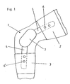
- Fig. 1 shows a knee 1 with an applied knee orthosis.
- the knee brace is there from a holding part 2 for the thigh and a holding part 3 for the Lower leg.
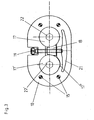
- Fig. 2 shows the structure of the orthotic joint 7 in longitudinal section. It consists of a base plate 8, in which two upwardly directed hexagon pins 14 are rotatable are stored. On the base plate there is a first intermediate plate 9, against which a flat housing 10 connects. The housing 10 houses the entrainment and Brake mechanism, which is described in more detail below. The housing is from a second intermediate plate 12 through which the hexagon pin 14th are rotatably passed through. On the second intermediate plate 11 and under one third intermediate plate 12 lay the end pieces of the rails 4, 5 that over Gears mesh with each other.
- the end pieces of the rails 4, 5 are non-rotatably connected to the hexagon pins 14, which are above the rails Have shoulders with which they rest under the third intermediate plate 12, however, with a tapered cylindrical end rotatable therethrough are led.
- a cover plate 13 is on the third intermediate plate 12 arranged, which is connected by screws 16 to the hexagon pin 14, wherein the screws 16 can rotate in the cover plate 13.
- the Base plate 8 is via screws or pins 15 with the lower two Intermediate plate 9, 11 and the intermediate housing 10 connected, so that the orthotic joint 7 represents a unit secured from above and below.
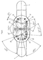
- Fig. 3 shows a plan view of the housing 10 with its mechanical parts, wherein all other elements of the orthotic joint are omitted.
- the disks have central hexagon bores 22, 22 ', with which they rotate on the (not shown here) hexagon pins are inserted.
- Such hex holes also have the end pieces of the rails (not shown here), so that if the rail twists towards each other, the disks 17, 17 'inevitably rotate.
- the right disk 17 is circular, while the left Disc has an eccentric section.
- Fig. 4 shows the end pieces of the rails 4, 5 with their toothings 23, 23 ' comb together. Both end pieces have hexagonal bores 22 ', with which, as described, they rotate with the (not shown here) Hexagon pins are connected. This makes them take-away and Brake mechanism connected, which was described in FIG. 3.
- the third intermediate plate 12 which has a number of bores 25, and the ends of the lower mounting pins 15.
- Elongated holes 24 which are concentric with the axes of rotation of the ends of the rails are not in the intermediate plate 12, but in the end pieces the rails arranged, which is only incorrect for clarity is shown to illustrate their interaction with the holes 25.
- the axes of rotation of the rails 4, 5 lie essentially in the longitudinal axis of the Hexagonal holes 22 '.
- pins 20 in Fig. 2 can be inserted through the holes 25, which are held in the top cover. These pens then run in desired elongated holes, so that the choice of permissible flexion and Extension angles for the knee is possible.
- Certain, exemplary angular range are shown here. Because the arrangement of holes and elongated holes like of course, others are desired Angular ranges possible. By the interaction of take-away and Brake mechanism with the end stops has the above-mentioned effect the user.
Abstract
Description
Die vorliegende Erfindung betrifft ein Orthesengelenk mit den Merkmalen des
Oberbegriffs des Anspruchs 1.The present invention relates to an orthotic joint with the features of
Preamble of
Ein einstellbares Orthesengelenk ist beispielsweise aus der EP-A-0 841 044 bekannt. Hier wird ein bestimmter voreinstellbarer Schwenkbereich der Orthese von einer Federkraft beaufschlagt, wobei die Feder für eine beaufschlagungsfreie Extensions- oder Flexionsbewegung außer Kraft gesetzt werden kann. Ein Orthesengelenk für Orthesen für zwei gegeneinander beug- und streckbare Körperteile, wie Knieorthesen oder Armorthesen, wobei das Orthesengelenk zwei Schienen drehbar miteinander verbindet, die jeweils mit oberen und unteren Orthesenteilen verbunden sind, die an dem jeweiligen Körperteil befestigbar sind und wobei an der Orthese jeweils lateral und/oder medial ein Schienenpaar mit Orthesengelenk angeordnet ist, wobei die Schienen endseitig über einen oder mehrere gemeinsame Zapfen oder durch endseitige Verzahnungen im Orthesengelenk miteinander in Eingriff stehen, und wobei für Streckung und/oder Beugung einstellbare Endanschläge vorhanden sind ist aus der EP-A-693 276 bekannt. Die EP-A-633 007 zeigt einen ähnlichen Aufbau, jedoch mit einem Klinkensystem.An adjustable orthotic joint is, for example, from EP-A-0 841 044 known. Here is a certain presettable swivel range of the orthosis acted upon by a spring force, the spring for an unstressed Extension or flexion movement can be overridden. On Orthotic joint for two orthoses that can be flexed and stretched Body parts, such as knee orthoses or arm orthoses, the orthotic joint being two Rails rotatably interconnect, each with upper and lower Orthosis parts are connected, which can be attached to the respective body part and with a pair of splints on the orthosis laterally and / or medially Orthosis joint is arranged, the rails on the end over or several common pins or by end gears in the Orthotic joint are in engagement with each other, and being used for extension and / or Diffraction adjustable end stops are available from EP-A-693 276 known. EP-A-633 007 shows a similar structure, but with one Jack system.
Aufgabe der vorliegenden Erfindung ist es, ein Orthesengelenk zu schaffen, dessen Extensions- oder Flexionsbereich einstellbar ist, wobei die Bewegung in einem bestimmten Bereich beaufschlagungsfrei erfolgt, jedoch vor Erreichen des jeweiligen Endpunkts auf eine entgegen wirkende, bremsende Kraft stößt. Damit soll eine schlagartige Belastung der Bänder, insbesondere von Kreuzbändern, vermieden werden, indem der Patient vor Errreichen des Endpunkts auf spürbaren Widerstand stößt. Zugleich hat dies den Effekt, daß die Rückkehr in eine neutrale Position angeregt wird.The object of the present invention is to create an orthotic joint, whose extension or flexion range is adjustable, the movement in in a certain area without load, but before reaching the respective end point encounters an opposing, braking force. In order to a sudden load on the ligaments, especially cruciate ligaments, be avoided by noticing the patient before reaching the end point Resistance meets. At the same time, this has the effect of returning to a neutral one Position is excited.
Diese Aufgabe wird mit den Merkmalen des kennzeichnenden Teils des
Anspruchs 1 gelöst. Fortbildungen und vorteilhafte Ausführungen der Erfindung
sind in den weiteren Ansprüchen umfaßt.This task is carried out with the characteristics of the characteristic part of the
Erfindungsgemäß ist ein Orthesengelenk für Orthesen für zwei gegeneinander beug- und streckbare Körperteile, wie Knieorthesen oder Armorthesen, wobei das Orthesengelenk zwei Schienen drehbar miteinander verbindet, die jeweils mit oberen und unteren Orthesenteilen verbunden sind, die an dem jeweiligen Körperteil befestigbar sind und wobei an der Orthese jeweils lateral und/oder medial ein Schienenpaar mit Orthesengelenk angeordnet ist, wobei die Schienen endseitig über einen oder mehrere gemeinsame Zapfen oder durch endseitige Verzahnungen im Orthesengelenk miteinander in Eingriff stehen, und wobei für Streckung und/oder Beugung einstellbare Endanschläge vorhanden sind, dadurch gekennzeichnet daß die Endanschläge über einen oder mehrere Winkelbereiche δ einstellbar sind und daß die Beugung, bzw. Streckung in dem Orthesengelenk in einem Winkelbereich von δ + α oder δ - α eine konstante oder dynamische Bremsung erfährt, wobei α einen Winkel von zwischen 3° und 25° darstellt.According to the invention, an orthotic joint for orthoses for two against each other flexible and extensible body parts, such as knee orthoses or arm orthoses, whereby the Orthotic joint rotatably connects two rails, each with upper and lower orthotic parts connected to each other Body part can be fastened and in each case laterally and / or on the orthosis medially a pair of splints with an orthotic joint is arranged, the splints on the end side via one or more common pins or on the end side Toothings in the orthotic joint are in engagement with one another, and being for Stretching and / or bending adjustable end stops are present, thereby characterized in that the end stops over one or more angular ranges δ are adjustable and that the flexion or extension in the orthotic joint in an angular range of δ + α or δ - α a constant or dynamic Braking experiences, where α represents an angle of between 3 ° and 25 °.
Die Bremsung erfolgt beispielsweise pneumatisch, hydraulisch oder durch ein elastisches Element, wobei ein Mitnehmer ab Erreichen des bestimmten Winkelbereichs ein Pneumatik- oder Hydraulikglied, das an der Orthese gelagert ist, auslöst, bzw. mit dem elastischen Element in Wirkverbindung kommt. Das Hydraulikglied kann auf niedrig- oder hochviskoser Basis wirken. Die Bremsung kann auch mechanisch durch Reibwirkung wenigstens zweier Teile erfolgen, die ab Erreichen des bestimmten Winkelbereichs in Eingriff miteinander kommen, wobei beispielsweise mit Reibbelägen beschichtete Platten verwendet werden können, deren Anlagedruck einstellbar gemacht werden kann. Es können auch reibende und elastische Elemente zusammenwirken, wie beispielsweise ein mit Federkraft .beaufschlagter Keil, wobei die Federkraft einstellbar sein kann. Das elastische Element kann eine Feder mit konstanter oder dynamischer Kennlinie sein oder aus einem natürlichen oder synthetischen Elastomer bestehen. Die Rückbewegung in die Ausgangsposition, d.h. im wesentlichen die Geradestellung des Gelenks, erfolgt ohne Beaufschlagung durch eine Bremskraft, die nur in Extensions- oder Flexionsrichtung wirkt.Braking takes place, for example, pneumatically, hydraulically or by means of a elastic element, whereby a driver from reaching the certain Angular range of a pneumatic or hydraulic element, which is mounted on the orthosis is, triggers or comes into operative connection with the elastic element. The Hydraulic link can act on a low or high viscosity basis. The braking can also be done mechanically by the friction effect of at least two parts come into engagement with each other once the specified angular range has been reached, plates, for example coated with friction linings, are used can, the system pressure can be made adjustable. It can too friction and elastic elements interact, such as a Spring force acted upon wedge, whereby the spring force can be adjustable. The elastic element can be a spring with constant or dynamic characteristic be or consist of a natural or synthetic elastomer. The Return movement to the starting position, i.e. essentially the straight position of the joint, is carried out without application of a braking force that is only in Extension or flexion direction works.
Nach einer bevorzugten Ausführung der Erfindung besteht das Orthesengelenk in ans sich bekannter Weise aus den Endstücken zweier Schienen, die an den jeweiligen Orthesenteilen befestigt sind und die endseitig Verzahnungen aufweisen, die miteinander kämmen, wobei sich die Endstücke der Schienen jeweils auf Zapfen einer diese verbindenden Grundplatte drehen. Erfindungsgemäß ist wenigstens ein Zapfen drehfest mit wenigstens einem Mitnehmer verbunden, der ab Erreichen des bestimmten Winkelbereichs unmittelbar oder über ein Zwischenglied auf ein oder mehrere elastische Elemente wirkt. Der Mitnehmer kann zum Beispiel ein Haken sein, der mit dem Ende einer Spiralfeder verbunden ist, die in einem Gehäuse auf der Grundplatte gelagert ist. Nach der bevorzugten Ausführung der Erfindung sind die Endstücke drehfest mit den Zapfen verbunden wobei der Mitnehmer eine exzentrische Scheibe ist, die drehfest mit den Zapfen verbunden ist und nach einem voreingestellten Weg mit einem Zwischenglied in reibenden Eingriff kommt, wobei schließlich die Scheibe eine in ihrer Drehrichtung erfolgende Bewegung des Zwischenglieds in Richtung einer auf dieses wirkenden Federkraft hervorruft. Das Zwischenglied wirkt auf eine Druckfeder, eine Blattfeder oder ein elastomeres Element, wobei die Kraft der Einwirkung des Zwischenglieds auf die Feder oder das elastomere Element einstellbar ist. Die Einstellung erfolgt durch eine Stellschraube, mit der zwischen dem Zwischenglied und dem elastischen Element eine gewünschte Vorspannung hergestellt wird. Die Einstellung der Endanschläge über Bohrungen oder Langlöcher der Endstücke erfolgt, in die Zapfen eingreifen, die ortsfest an einer Abdeckplatte für die Endstücke angeordnet sind. According to a preferred embodiment of the invention, the orthotic joint consists of in a manner known per se from the end pieces of two rails connected to the respective orthosis parts are attached and the end teeth have, which mesh with each other, the end pieces of the rails each turn on the pin of a base plate connecting them. According to the invention, at least one pin is non-rotatable with at least one Driver connected, which reaches the specified angular range directly or via an intermediate link to one or more elastic elements acts. The driver can for example be a hook that ends with a Spiral spring is connected, which is mounted in a housing on the base plate. According to the preferred embodiment of the invention, the end pieces are non-rotatable connected to the pin, the driver being an eccentric disk, the is non-rotatably connected to the spigot and according to a preset path an intermediate member comes into frictional engagement, eventually the disc a movement of the intermediate link in the direction of rotation one causes spring force acting on it. The pontic acts a compression spring, a leaf spring or an elastomeric element, the force the action of the intermediate member on the spring or the elastomeric element is adjustable. The setting is made using an adjusting screw with which between the intermediate member and the elastic element a desired bias will be produced. The setting of the end stops via holes or Elongated holes in the end pieces are made, engage in the pegs that are fixed on one Cover plate for the end pieces are arranged.
Im folgenden wird die Erfindung anhand von Zeichnungen beispielhaft näher
beschrieben. Es zeigen:
Fig. 1 zeigt ein Knie 1 mit einer angelegten Knieorthese. Die Knieorthese besteht
aus einem Halteteil 2 für den Oberschenkel und einem Halteteil 3 für den
Unterschenkel. In den Halteteilen sind lateral und medial jeweils Metallschienen
4, 5 mittels Nieten 6 befestigt, wobei sich die Schiene 5 des Halteteils 2 für den
Oberschenkel nach unten und die Schiene 4 des Halteteils 3 für den Unterschenkel
nach oben erstrecken. Beide Schienen vereinigen sich in dem Orthesengelenk 7,
in dem sie über einen bestimmten Winkelbereich drehbar gelagert sind und über
eine Verzahnung miteinander in Eingriff stehen.Fig. 1 shows a
Fig. 2 zeigt den Aufbau des Orthesengelenks 7 im Längsschnitt. Es besteht aus
einer Grundplatte 8, in der zwei nach oben gerichtete Sechskantzapfen 14 drehbar
gelagert sind. Auf der Grundplatte liegt eine erste Zwischenplatte 9, an die sich
ein flaches Gehäuse 10 anschließt. Das Gehäuse 10 beherbergt die Mitnahme- und
Bremsmechanik, die weiter unten näher beschrieben wird. Das Gehäuse wird von
einer zweiten Zwischenplatte 12 abgedeckt, durch die die Sechskantzapfen 14
drehbar hindurch geführt sind. Auf der zweiten Zwischenplatte 11 und unter einer
dritten Zwischenplatte 12 legen die Endstücke der Schienen 4, 5, die über
Verzahnungen miteinander in Eingriff stehen. Die Endstücke der Schienen 4, 5
sind drehfest mit den Sechskantzapfen 14 verbunden, die über den Schienen
Schultern aufweisen, mit denen sie unter der dritten Zwischenplatte 12 anliegen,
jedoch mit einem verjüngten zylindrischen Ende drehbar durch diese hindurch
geführt sind. Auf der dritten Zwischenplatte 12 ist eine Abdeckplatte 13
angeordnet, die durch Schrauben 16 mit den Sechskantzapfen 14 verbunden ist,
wobei sich die Schrauben 16 in der Abdeckplatte 13 drehen können. Die
Grundplatte 8 ist über Schrauben oder Stifte 15 mit den unteren beiden
Zwischenplatte 9, 11 und dem dazwischen liegenden Gehäuse 10 verbunden, so
daß das Orthesengelenk 7 eine von oben und unten gesicherte Einheit darstellt.Fig. 2 shows the structure of the
Fig. 3 zeigt eine Draufsicht auf das Gehäuse 10 mit seinen Mechanikteilen, wobei
alle anderen Elemente des Orthesengelenks weggelassen sind. Zu erkennen sind
vier untere Befestigungsstifte 15, die seitlich an den Enden angeordnet sind. Es
sind zwei Ausnehmungen vorhanden, in denen in einem Abstand zueinander in
der Längsachse des Gelenks zwei Scheiben 17, 17' angeordnet sind. Die Scheiben
weisen zentrale Sechskantbohrungen 22, 22' auf, mit denen sie drehfest auf die
(hier nicht gezeigten) Sechskantzapfen gesteckt sind. Solche Sechskantbohrungen
weisen auch die (hier nicht gezeigten) Endstücke der Schienen auf, so daß sich,
wenn sich die Schiene zueinander verdrehen, die Scheiben 17, 17' zwangsläufig
mitdrehen. Die rechte Scheibe 17 ist kreisrund ausgeführt, während die linke
Scheibe einen exzentrischen Abschnitt aufweist. Zwischen den Scheiben ist ein
Keil 18 angeordnet, der mit einer Gewindebohrung verdrehsicher zwischen den
(hier nicht gezeigten) Zwischenplatten auf einem Gewindebolzen läuft. Der
Gewindebolzen 19 ist mit seinem inneren Ende an einem elastischen Element 21
gelagert, das ihn mit Federkraft beaufschlagt und nach außen zu drücken trachtet.
Dabei nimmt der Gewindebolzen 19 den Keil 18 mit, der mit seinen Keilflächen
als Bremskeil an der Außenkontur der Scheiben 17, 17' anliegt. Je tiefer der
Gewindebolzen 19 eingeschraubt wird, desto höher ist die auf ihn und den Keil 18
wirkende Kraft. Während zwischen der kreisrunden Scheibe 17 und dem Keil 18
eine im wesentlichen gleichbleibende Reibung vorhanden wäre, kommt bei einer
Drehung der linken Scheibe 17' entgegen dem Uhrzeigersinn deren sich
exzentrisch vergrößernder Außenumfang in eine immer größer werdende
Reibung mit dem Keil 18, die gleichzeitig auf die kreisrunde Scheibe 17
übertragen wird, so daß sich zwischen dem Keil und den Scheiben eine stärker
werdende Bremskraft bis zur Blockade einstellen würde, würde der Weg der
Scheiben nicht durch die unten geschilderten Maßnahmen begrenzt. Durch diese
Begrenzung kommt es nach einem Bereich geringer Reibung nach Eingriff eines
Teils des exzentrischen Bereichs der linken Scheibe zu einem Bereich größerer
Reibung, was sich für den Benutzer so darstellt, daß er bei beginnender Flexion
oder Extension zunächst keinen oder nur geringen Widerstand spürt, der vor
Erreichen der Endstellung durch ein spürbares Abbremsen abgelöst wird. Die
Form des Keils 18 bedingt, daß dieser nur in einer Richtung bremsend wirkt, in
der er auf die Scheiben gepreßt wird. In der anderen Richtung, d.h. bei einer
Bewegung zurück, übt der Keil keine Bremskraft aus.Fig. 3 shows a plan view of the
Fig. 4 zeigt die Endstücke der Schienen 4, 5 mit ihren Verzahnungen 23, 23', die
miteinander kämmen. Beide Endstücke weisen Sechskantbohrungen 22' auf, mit
denen sie, wie geschildert, drehfest mit den (hier nicht gezeigten)
Sechskantzapfen verbunden sind. Dadurch sind sie mit der Mitnahme- und
Bremsmechanik verbunden, die zu Fig. 3 beschrieben wurde. Auf den Endstücken
liegt die dritte Zwischenplatte 12, die eine Anzahl von Bohrungen 25 aufweist,
sowie die Enden der unteren Befestigungsstifte 15. Die hier dargestellten
Langlöcher 24, die konzentrisch zu den Drehachsen der Enden der Schienen
ausgerichtet sind, sind nicht in der Zwischenplatte 12, sondern in den Endstücken
der Schienen angeordnet, was nur zur Verdeutlichung zeichnerisch unkorrekt
dargestellt ist, um ihr Zusammenwirken mit den Bohrungen 25 zu verdeutlichen.
Die Drehachsen der Schienen 4, 5 liegen im wesentlichen in der Längsachse der
Sechskantbohrungen 22'. Zur Einstellungen von Endanschlägen für die Schienen
4, 5 können Stifte (Stifte 20 in Fig. 2) durch die Bohrungen 25 gesteckt werden,
die in der oberen Abdeckung gehalten werden. Diese Stifte laufen dann in
gewünschten Langlöchern, so daß die Wahl von zulässigen Beuge- und
Streckwinkeln für das Knie möglich ist. Bestimmte, beispielhafte Winkelbereich
sind hier dargestellt. Da die Anordnung von Bohrungen und Langlöchern wie
gewünscht ausgeführt werden kann, sind selbstverständlich andere
Winkelbereiche möglich. Durch das Zusammenwirken der Mitnahme- und
Bremsmechanik mit den Endanschlägen stellt sich der oben genannte Effekt für
den Benutzer ein.Fig. 4 shows the end pieces of the
Claims (10)
wobei das Orthesengelenk (7) zwei Schienen (4, 5) drehbar miteinander verbindet, die jeweils mit oberen und unteren Orthesenteilen (2, 3) verbunden sind, die an dem jeweiligen Körperteil befestigbar sind und wobei an der Orthese jeweils lateral und/oder medial ein Schienenpaar mit Orthesengelenk angeordnet ist,
wobei die Schienen endseitig über einen oder mehrere gemeinsame Zapfen oder durch endseitige Verzahnungen (23, 23') im Orthesengelenk (7) miteinander in Eingriff stehen, und wobei für Streckung und/oder Beugung einstellbare Endanschläge (20) vorhanden sind,
und wobei die Endanschläge über einen Winkelbereich δ verstellbar sind,
dadurch gekennzeichnet, daß die Beugung, bzw. Streckung in dem Orthesengelenk (7) in einem bestimmten Winkelbereich beaufschlagungsfrei erfolgt und in einem anschließenden Winkelbereich α eine Bremsung erfährt, wobei α einen Winkel von zwischen 3° und 25° darstellt,
und daß die Bremsung durch ein elastisches Glied (21) erfolgt, wobei ein Mitnehmer (17') ab Erreichen des bestimmten Winkelbereichs ein Pneumatikoder Hydraulikglied, das an der Orthese gelagert ist, auslöst, bzw. mit dem elastischen Glied (21) in Wirkverbindung kommt, wobei das Pneumatik- oder Hydraulikglied, bzw. das elastische Glied eine konstante Kennlinie aufweist.Orthosis with an orthotic joint for two body parts that can be flexed and stretched against each other, such as knee orthoses or arm orthoses,
wherein the orthotic joint (7) rotatably connects two rails (4, 5) to each other, which are each connected to upper and lower orthotic parts (2, 3), which can be fastened to the respective body part, and wherein the orthosis is laterally and / or medially a pair of rails with an orthotic joint is arranged,
the ends of the rails being in engagement with one another via one or more common pins or through end toothings (23, 23 ') in the orthotic joint (7), and with adjustable end stops (20) for extension and / or flexion,
and the end stops are adjustable over an angular range δ,
characterized in that the flexion or extension in the orthotic joint (7) takes place without stress in a certain angular range and braking occurs in a subsequent angular range α, where α represents an angle of between 3 ° and 25 °,
and that braking is effected by an elastic member (21), a driver (17 ') triggering a pneumatic or hydraulic member, which is mounted on the orthosis, or reaching an operative connection with the elastic member (21) after reaching the specific angular range , wherein the pneumatic or hydraulic member, or the elastic member has a constant characteristic.
dadurch gekennzeichnet, daß die Bremsung mechanisch durch Reibwirkung wenigstens zweier Teile erfolgt, die ab Erreichen des bestimmten Winkelbereichs in Eingriff miteinander kommen. Orthosis according to claim 1,
characterized in that the braking takes place mechanically by the frictional action of at least two parts which come into engagement with one another once the specific angular range has been reached.
dadurch gekennzeichnet, daß das Orthesengelenk aus den Endstücken zweier Schienen besteht, die an den jeweiligen Orthesenteilen befestigt sind,
daß die Schienen endseitig Verzahnungen aufweisen, die miteinander kämmen, und daß die Endstücke der Schienen jeweils auf Zapfen einer diese verbindenden Grundplatte drehen.Orthosis according to one of the preceding claims,
characterized in that the orthotic joint consists of the end pieces of two rails which are attached to the respective orthosis parts,
that the rails have end teeth that mesh with each other, and that the end pieces of the rails each rotate on pins of a base plate connecting them.
dadurch gekennzeichnet, daß die Zapfen drehfest mit Mitnehmern verbunden sind, die ab Erreichen des bestimmten Winkelbereichs unmittelbar oder über ein Zwischenglied auf eine oder mehrere Federn wirken.Orthosis according to claim 3,
characterized in that the pins are non-rotatably connected to drivers which act directly or via an intermediate member on one or more springs from reaching the certain angular range.
dadurch gekennzeichnet, daß die Mitnehmer Haken sind, die mit dem Ende von Spiralfedern verbunden sind,
und daß die Spiralfedern in einem oder mehreren Gehäusen auf der Grundplatte gelagert sind.Orthosis claim 4,
characterized in that the catches are hooks connected to the end of coil springs,
and that the coil springs are mounted in one or more housings on the base plate.
dadurch gekennzeichnet, daß die Endstücke drehfest mit den Zapfen verbunden sind,
daß die Mitnehmer runde oder exzentrische Scheiben sind, die drehfest mit den Zapfen verbunden sind,
und daß die Scheiben eine in ihrer Drehrichtung erfolgende Bewegung eines zwischen ihnen angeordneten und mit diesen in Kontakt stehenden Zwischenglieds in Richtung einer auf dieses wirkenden Federkraft hervorrufen.Orthosis according to claim 5,
characterized in that the end pieces are non-rotatably connected to the pins,
that the drivers are round or eccentric disks that are non-rotatably connected to the pins,
and that the disks cause a movement of an intermediate member arranged between them and in contact with them in the direction of their rotation in the direction of a spring force acting thereon.
dadurch gekennzeichnet, daß das Zwischenglied auf eine Druckfeder oder eine Blattfeder wirkt.Orthosis according to claim 5,
characterized in that the intermediate member acts on a compression spring or a leaf spring.
dadurch gekennzeichnet, daß die Kraft der Einwirkung des Zwischenglieds auf die Feder einstellbar ist.Orthosis according to claim 7,
characterized in that the force of the action of the intermediate member on the spring is adjustable.
dadurch gekennzeichnet, dass die Einstellung durch eine Stellschraube (19) erfolgt, mit der zwischen dem Zwischenglied und dem elastischen Element eine gewünschte Vorspannung hergestellt wird.Orthosis according to claim 8,
characterized in that the setting is carried out by means of an adjusting screw (19) with which a desired prestress is produced between the intermediate member and the elastic element.
dadurch gekennzeichnet, dass die Einstellung der Endanschläge über Bohrungen oder Langlöcher (24) der Endstücke erfolgt, in die Zapfen (20) eingreifen, die ortsfest an einer Abdeckplatte für die Endstücke angeordnet sind..Orthosis according to claim 7,
characterized in that the end stops are adjusted via bores or elongated holes (24) of the end pieces, into which pins (20) engage, which are arranged in a fixed position on a cover plate for the end pieces.
Applications Claiming Priority (3)
| Application Number | Priority Date | Filing Date | Title |
|---|---|---|---|
| DE29914375U | 1999-08-17 | ||
| DE29914375U DE29914375U1 (en) | 1999-08-17 | 1999-08-17 | Orthotic joint |
| EP00954354A EP1121077B1 (en) | 1999-08-17 | 2000-07-22 | Orthesis joint |
Related Parent Applications (1)
| Application Number | Title | Priority Date | Filing Date |
|---|---|---|---|
| EP00954354A Division EP1121077B1 (en) | 1999-08-17 | 2000-07-22 | Orthesis joint |
Publications (3)
| Publication Number | Publication Date |
|---|---|
| EP1358862A2 true EP1358862A2 (en) | 2003-11-05 |
| EP1358862A3 EP1358862A3 (en) | 2003-12-03 |
| EP1358862B1 EP1358862B1 (en) | 2004-11-17 |
Family
ID=8077619
Family Applications (2)
| Application Number | Title | Priority Date | Filing Date |
|---|---|---|---|
| EP00954354A Revoked EP1121077B1 (en) | 1999-08-17 | 2000-07-22 | Orthesis joint |
| EP03009209A Expired - Lifetime EP1358862B1 (en) | 1999-08-17 | 2000-07-22 | Orthesis |
Family Applications Before (1)
| Application Number | Title | Priority Date | Filing Date |
|---|---|---|---|
| EP00954354A Revoked EP1121077B1 (en) | 1999-08-17 | 2000-07-22 | Orthesis joint |
Country Status (7)
| Country | Link |
|---|---|
| US (1) | US6666837B2 (en) |
| EP (2) | EP1121077B1 (en) |
| JP (1) | JP2003506194A (en) |
| AT (2) | ATE282382T1 (en) |
| DE (3) | DE29914375U1 (en) |
| DK (1) | DK1121077T3 (en) |
| WO (1) | WO2001012110A1 (en) |
Families Citing this family (34)
| Publication number | Priority date | Publication date | Assignee | Title |
|---|---|---|---|---|
| US6383156B1 (en) * | 1999-09-27 | 2002-05-07 | Dj Orthopedics, Llc | Orthopaedic brace having a range of motion hinge with an adjustable-length strut |
| DE10005764B4 (en) * | 2000-02-10 | 2005-12-15 | Albrecht Gmbh | Orthosis with adjustment of the flexion and extension stop by rail pivoting movements |
| US6821261B2 (en) * | 2000-12-12 | 2004-11-23 | Dj Orthopedics, Llc | Orthopedic brace having length-adjustable supports |
| US6969363B2 (en) * | 2002-02-15 | 2005-11-29 | Thuasne | Bicentric hinge for use in a brace |
| US7488300B2 (en) | 2002-02-15 | 2009-02-10 | Thusane | Bicentric hinge for use in a brace |
| ATE535216T1 (en) | 2002-04-25 | 2011-12-15 | Ultraflex Systems Inc | MOVABLE KNEE JOINT |
| US8100844B2 (en) | 2002-04-25 | 2012-01-24 | Ultraflex Systems, Inc. | Ambulating ankle and knee joints with bidirectional dampening and assistance using elastomeric restraint |
| US6936020B2 (en) * | 2003-01-16 | 2005-08-30 | Perry H. Davis | Orthopedic splint |
| US7192407B2 (en) * | 2003-01-30 | 2007-03-20 | Djo, Llc | Motion controlling hinge for orthopedic brace |
| US7150721B2 (en) * | 2003-06-30 | 2006-12-19 | Thuasne | Knee brace with dynamic counterforce |
| US20050273025A1 (en) * | 2004-05-19 | 2005-12-08 | Houser Guy M | Braces having an assembly for exerting a manually adjustable force on a limb of a user |
| US7811242B2 (en) | 2004-06-24 | 2010-10-12 | Djo, Llc | Motion controlling hinge for orthopedic brace |
| WO2006088466A1 (en) * | 2005-02-15 | 2006-08-24 | Ian K Engelman | An articulated orthosis providing lift assist |
| DE102006026068A1 (en) * | 2006-04-05 | 2007-12-20 | Michael Ottleben | Knee orthosis has element in fixed position on femur joint part that interacts with curved tibia joint part profile so element distance from sliding element reduces in defined manner to force desired motion of sliding element in guide slot |
| US7485103B2 (en) * | 2006-04-13 | 2009-02-03 | Breg, Inc. | Rotational hinge assembly for a knee brace having an osteoarthritis treatment function |
| US7544174B2 (en) | 2006-09-29 | 2009-06-09 | Djo, Llc | Quiet flexion/extension stop for orthopedic brace and orthopedic brace incorporating a quiet flexion/extension stop |
| DE102008024748A1 (en) | 2008-05-20 | 2009-12-03 | Otto Bock Healthcare Gmbh | Knee orthosis and method for controlling a knee brace |
| US7931609B2 (en) * | 2008-08-21 | 2011-04-26 | Christophe Blanchard | Extremity support apparatus and method |
| US9289640B2 (en) * | 2009-03-23 | 2016-03-22 | Steven M. Cersonsky | Resistance brace |
| US20110065553A1 (en) * | 2009-03-23 | 2011-03-17 | Cersonsky Steven M | Body Mounted Muscular Brace |
| US9220624B2 (en) | 2010-09-16 | 2015-12-29 | Ossur Hf | Posterior cruciate ligament support brace |
| AT510404B1 (en) * | 2011-05-19 | 2012-04-15 | Kurt Wayd | SUPPORTING BASKET FOR KNEE ORTHESES BZW. KNEE-SUPPORT |
| CA2852695C (en) | 2011-10-31 | 2019-10-01 | Ossur Hf | Orthopedic device for dynamically treating the knee |
| FR2997294B1 (en) * | 2012-10-30 | 2014-12-19 | Gibaud | HOLDING DEVICE FOR THE BALL AND KNEE ORTHESIS |
| WO2014117109A1 (en) | 2013-01-25 | 2014-07-31 | Ossur Hf | Orthopedic device having a dynamic control system |
| US9539135B2 (en) | 2013-01-25 | 2017-01-10 | Ossur Hf | Orthopedic device having a dynamic control system and method for using the same |
| US10413437B2 (en) | 2013-01-25 | 2019-09-17 | Ossur Iceland Ehf | Orthopedic device having a dynamic control system and method for using the same |
| KR101460893B1 (en) * | 2013-05-28 | 2014-11-12 | 장기용 | Knee retractor |
| WO2014205103A1 (en) | 2013-06-21 | 2014-12-24 | Ossur Hf | Dynamic tension system for orthopedic device |
| EP3036068B1 (en) | 2013-08-22 | 2018-09-19 | Ossur Iceland EHF | Torque limiting tool and method for using the same |
| WO2016007704A1 (en) | 2014-07-11 | 2016-01-14 | Ossur Hf | Tightening system with a tension control mechanism |
| US10653546B2 (en) | 2014-10-31 | 2020-05-19 | Ossur Hf | Orthopedic device having a dynamic control system |
| WO2019104302A2 (en) | 2017-11-27 | 2019-05-31 | Ossur Iceland Ehf | Orthopedic device having a suspension element |
| DE102019116417A1 (en) * | 2019-06-17 | 2020-12-17 | Michael Wagner | Orthosis with a joint device and joint device that simulates a bicondylar joint |
Citations (4)
| Publication number | Priority date | Publication date | Assignee | Title |
|---|---|---|---|---|
| US5031606A (en) * | 1991-01-17 | 1991-07-16 | Randolph Austin Company | Brace and hinge apparatus and method |
| US5036837A (en) * | 1990-02-09 | 1991-08-06 | Bio-Tec, Inc. | Dynamic extension splint |
| EP0693276A1 (en) * | 1994-07-19 | 1996-01-24 | Professional Care Products Inc. | Improved orthopaedic polycentric hinge |
| EP0841044A1 (en) * | 1996-10-31 | 1998-05-13 | Albrecht GmbH | Dynamic brace |
Family Cites Families (7)
| Publication number | Priority date | Publication date | Assignee | Title |
|---|---|---|---|---|
| US5749840A (en) * | 1989-12-07 | 1998-05-12 | Ultraflex Systems, Inc. | Dynamic splint |
| US5437619A (en) * | 1993-06-30 | 1995-08-01 | Empi, Inc. | Range-of-motion splint with eccentric spring |
| US5409449A (en) | 1993-07-09 | 1995-04-25 | Smith & Nephew Donjoy Inc. | Detent mechanism for a hinged orthopedic brace |
| US5437611A (en) * | 1993-12-01 | 1995-08-01 | Orthotic Rehabilitation Products, Inc. | Dynamic brace joint |
| US5899869A (en) * | 1997-12-22 | 1999-05-04 | Barrack, Jr.; Herb J. | Orthopedic appliance with weight activated brake and variable extension assist |
| DE19605734C2 (en) * | 1996-02-16 | 2000-01-20 | Beiersdorf Ag | Knee joint orthosis with different lateral and medial orthotic joint |
| US6129690A (en) * | 1998-07-29 | 2000-10-10 | Empi Corp. | Unidirectional resistance pivot assembly for a splint |
-
1999
- 1999-08-17 DE DE29914375U patent/DE29914375U1/en not_active Expired - Lifetime
-
2000
- 2000-07-22 DK DK00954354T patent/DK1121077T3/en active
- 2000-07-22 EP EP00954354A patent/EP1121077B1/en not_active Revoked
- 2000-07-22 EP EP03009209A patent/EP1358862B1/en not_active Expired - Lifetime
- 2000-07-22 AT AT03009209T patent/ATE282382T1/en not_active IP Right Cessation
- 2000-07-22 DE DE50004147T patent/DE50004147D1/en not_active Revoked
- 2000-07-22 DE DE50008709T patent/DE50008709D1/en not_active Expired - Fee Related
- 2000-07-22 AT AT00954354T patent/ATE252355T1/en active
- 2000-07-22 WO PCT/DE2000/002385 patent/WO2001012110A1/en active IP Right Grant
- 2000-07-22 JP JP2001516457A patent/JP2003506194A/en active Pending
-
2001
- 2001-04-17 US US09/837,635 patent/US6666837B2/en not_active Expired - Fee Related
Patent Citations (4)
| Publication number | Priority date | Publication date | Assignee | Title |
|---|---|---|---|---|
| US5036837A (en) * | 1990-02-09 | 1991-08-06 | Bio-Tec, Inc. | Dynamic extension splint |
| US5031606A (en) * | 1991-01-17 | 1991-07-16 | Randolph Austin Company | Brace and hinge apparatus and method |
| EP0693276A1 (en) * | 1994-07-19 | 1996-01-24 | Professional Care Products Inc. | Improved orthopaedic polycentric hinge |
| EP0841044A1 (en) * | 1996-10-31 | 1998-05-13 | Albrecht GmbH | Dynamic brace |
Also Published As
| Publication number | Publication date |
|---|---|
| WO2001012110A1 (en) | 2001-02-22 |
| EP1358862A3 (en) | 2003-12-03 |
| US20020026136A1 (en) | 2002-02-28 |
| DE50004147D1 (en) | 2003-11-27 |
| ATE252355T1 (en) | 2003-11-15 |
| DE50008709D1 (en) | 2004-12-23 |
| EP1121077B1 (en) | 2003-10-22 |
| ATE282382T1 (en) | 2004-12-15 |
| DE29914375U1 (en) | 1999-11-25 |
| JP2003506194A (en) | 2003-02-18 |
| EP1358862B1 (en) | 2004-11-17 |
| US6666837B2 (en) | 2003-12-23 |
| DK1121077T3 (en) | 2004-02-16 |
| EP1121077A1 (en) | 2001-08-08 |
Similar Documents
| Publication | Publication Date | Title |
|---|---|---|
| EP1121077B1 (en) | Orthesis joint | |
| EP0713689B1 (en) | Pivoting device between parts of an orthopedic aid | |
| DE69727479T2 (en) | ANGLE COMPENSATION DEVICE FOR JOINT SUPPORT | |
| DE60310199T2 (en) | ARTICULAR CORES WITH TELESCOPIC MOVABLE CONDYLAR PAD | |
| EP1854434B1 (en) | Jointed orthesis | |
| DE2754422C2 (en) | Brake arrangement for a knee joint prosthesis | |
| EP1761218B1 (en) | Prosthetic joint | |
| EP0760641B9 (en) | Orthosis | |
| EP3352713B1 (en) | Dynamic articulation support | |
| DE3036580A1 (en) | JOINT FITTING FOR SEATS WITH ADJUSTABLE BACKREST, IN PARTICULAR MOTOR VEHICLE SEATS | |
| EP0546330B1 (en) | Motion brace | |
| DE3320274A1 (en) | CORRECTION AND PROTECTION ASSOCIATION FOR A HUMAN JOINT, ESPECIALLY A KNEE | |
| EP3716920B1 (en) | Orthosis, system and procedure for adapting an orthosis | |
| EP2179708A1 (en) | Error-free safety prosthesis joint | |
| DE102008049854B4 (en) | Orthosis for correcting malpositions and redressing of limbs in the abduction or adduction direction | |
| DE602004000583T3 (en) | Articulated connection for a postoperative orthosis | |
| DE102021121819A1 (en) | Adjustable orthosis joint for controlled movement and/or fixation of a hand and orthosis with such an orthosis joint | |
| EP3281610A1 (en) | Orthosis | |
| DE102015005572B4 (en) | Knee orthosis for applying a ventrally or dorsally directed translational force | |
| DE19933197B4 (en) | Polycentric joint support with gear adjustment mechanism for stepless fine adjustment of a swivel range limit | |
| EP3681445A1 (en) | Joint device | |
| EP3146944B1 (en) | Wrist orthotic | |
| EP2979674B1 (en) | Birthing bed with a retaining handle and braking device | |
| DE102018131929B4 (en) | Joint for an ankle orthosis | |
| DE102020103107A1 (en) | ORTHESIS JOINTS |
Legal Events
| Date | Code | Title | Description |
|---|---|---|---|
| PUAI | Public reference made under article 153(3) epc to a published international application that has entered the european phase |
Free format text: ORIGINAL CODE: 0009012 |
|
| PUAL | Search report despatched |
Free format text: ORIGINAL CODE: 0009013 |
|
| 17P | Request for examination filed |
Effective date: 20030521 |
|
| AC | Divisional application: reference to earlier application |
Ref document number: 1121077 Country of ref document: EP Kind code of ref document: P |
|
| AK | Designated contracting states |
Kind code of ref document: A2 Designated state(s): AT BE CH CY DE DK ES FI FR GB GR IE IT LI LU MC NL PT SE |
|
| AK | Designated contracting states |
Kind code of ref document: A3 Designated state(s): AT BE CH CY DE DK ES FI FR GB GR IE IT LI LU MC NL PT SE |
|
| GRAP | Despatch of communication of intention to grant a patent |
Free format text: ORIGINAL CODE: EPIDOSNIGR1 |
|
| AKX | Designation fees paid |
Designated state(s): AT BE CH CY DE DK ES FI FR GB GR IE IT LI LU MC NL PT SE |
|
| GRAS | Grant fee paid |
Free format text: ORIGINAL CODE: EPIDOSNIGR3 |
|
| GRAA | (expected) grant |
Free format text: ORIGINAL CODE: 0009210 |
|
| AC | Divisional application: reference to earlier application |
Ref document number: 1121077 Country of ref document: EP Kind code of ref document: P |
|
| AK | Designated contracting states |
Kind code of ref document: B1 Designated state(s): AT BE CH CY DE DK ES FI FR GB GR IE IT LI LU MC NL PT SE |
|
| PG25 | Lapsed in a contracting state [announced via postgrant information from national office to epo] |
Ref country code: IT Free format text: LAPSE BECAUSE OF FAILURE TO SUBMIT A TRANSLATION OF THE DESCRIPTION OR TO PAY THE FEE WITHIN THE PRESCRIBED TIME-LIMIT;WARNING: LAPSES OF ITALIAN PATENTS WITH EFFECTIVE DATE BEFORE 2007 MAY HAVE OCCURRED AT ANY TIME BEFORE 2007. THE CORRECT EFFECTIVE DATE MAY BE DIFFERENT FROM THE ONE RECORDED. Effective date: 20041117 Ref country code: FR Free format text: LAPSE BECAUSE OF FAILURE TO SUBMIT A TRANSLATION OF THE DESCRIPTION OR TO PAY THE FEE WITHIN THE PRESCRIBED TIME-LIMIT Effective date: 20041117 Ref country code: FI Free format text: LAPSE BECAUSE OF FAILURE TO SUBMIT A TRANSLATION OF THE DESCRIPTION OR TO PAY THE FEE WITHIN THE PRESCRIBED TIME-LIMIT Effective date: 20041117 Ref country code: IE Free format text: LAPSE BECAUSE OF FAILURE TO SUBMIT A TRANSLATION OF THE DESCRIPTION OR TO PAY THE FEE WITHIN THE PRESCRIBED TIME-LIMIT Effective date: 20041117 Ref country code: NL Free format text: LAPSE BECAUSE OF FAILURE TO SUBMIT A TRANSLATION OF THE DESCRIPTION OR TO PAY THE FEE WITHIN THE PRESCRIBED TIME-LIMIT Effective date: 20041117 Ref country code: GB Free format text: LAPSE BECAUSE OF FAILURE TO SUBMIT A TRANSLATION OF THE DESCRIPTION OR TO PAY THE FEE WITHIN THE PRESCRIBED TIME-LIMIT Effective date: 20041117 |
|
| REG | Reference to a national code |
Ref country code: GB Ref legal event code: FG4D Free format text: NOT ENGLISH |
|
| REG | Reference to a national code |
Ref country code: CH Ref legal event code: EP |
|
| REG | Reference to a national code |
Ref country code: IE Ref legal event code: FG4D Free format text: GERMAN |
|
| REF | Corresponds to: |
Ref document number: 50008709 Country of ref document: DE Date of ref document: 20041223 Kind code of ref document: P |
|
| PG25 | Lapsed in a contracting state [announced via postgrant information from national office to epo] |
Ref country code: SE Free format text: LAPSE BECAUSE OF FAILURE TO SUBMIT A TRANSLATION OF THE DESCRIPTION OR TO PAY THE FEE WITHIN THE PRESCRIBED TIME-LIMIT Effective date: 20050217 Ref country code: DK Free format text: LAPSE BECAUSE OF FAILURE TO SUBMIT A TRANSLATION OF THE DESCRIPTION OR TO PAY THE FEE WITHIN THE PRESCRIBED TIME-LIMIT Effective date: 20050217 Ref country code: GR Free format text: LAPSE BECAUSE OF FAILURE TO SUBMIT A TRANSLATION OF THE DESCRIPTION OR TO PAY THE FEE WITHIN THE PRESCRIBED TIME-LIMIT Effective date: 20050217 |
|
| PG25 | Lapsed in a contracting state [announced via postgrant information from national office to epo] |
Ref country code: ES Free format text: LAPSE BECAUSE OF FAILURE TO SUBMIT A TRANSLATION OF THE DESCRIPTION OR TO PAY THE FEE WITHIN THE PRESCRIBED TIME-LIMIT Effective date: 20050228 |
|
| NLV1 | Nl: lapsed or annulled due to failure to fulfill the requirements of art. 29p and 29m of the patents act | ||
| GBV | Gb: ep patent (uk) treated as always having been void in accordance with gb section 77(7)/1977 [no translation filed] |
Effective date: 20041117 |
|
| REG | Reference to a national code |
Ref country code: IE Ref legal event code: FD4D |
|
| PG25 | Lapsed in a contracting state [announced via postgrant information from national office to epo] |
Ref country code: LU Free format text: LAPSE BECAUSE OF NON-PAYMENT OF DUE FEES Effective date: 20050722 Ref country code: CY Free format text: LAPSE BECAUSE OF FAILURE TO SUBMIT A TRANSLATION OF THE DESCRIPTION OR TO PAY THE FEE WITHIN THE PRESCRIBED TIME-LIMIT Effective date: 20050722 Ref country code: AT Free format text: LAPSE BECAUSE OF NON-PAYMENT OF DUE FEES Effective date: 20050722 |
|
| PG25 | Lapsed in a contracting state [announced via postgrant information from national office to epo] |
Ref country code: LI Free format text: LAPSE BECAUSE OF NON-PAYMENT OF DUE FEES Effective date: 20050731 Ref country code: BE Free format text: LAPSE BECAUSE OF NON-PAYMENT OF DUE FEES Effective date: 20050731 Ref country code: CH Free format text: LAPSE BECAUSE OF NON-PAYMENT OF DUE FEES Effective date: 20050731 Ref country code: MC Free format text: LAPSE BECAUSE OF NON-PAYMENT OF DUE FEES Effective date: 20050731 |
|
| PLBE | No opposition filed within time limit |
Free format text: ORIGINAL CODE: 0009261 |
|
| STAA | Information on the status of an ep patent application or granted ep patent |
Free format text: STATUS: NO OPPOSITION FILED WITHIN TIME LIMIT |
|
| 26N | No opposition filed |
Effective date: 20050818 |
|
| EN | Fr: translation not filed | ||
| REG | Reference to a national code |
Ref country code: CH Ref legal event code: PL |
|
| BERE | Be: lapsed |
Owner name: *MEDI BAYREUTH WEIHERMULLER & VOIGTMANN G.M.B.H. & Effective date: 20050731 |
|
| PG25 | Lapsed in a contracting state [announced via postgrant information from national office to epo] |
Ref country code: PT Free format text: LAPSE BECAUSE OF NON-PAYMENT OF DUE FEES Effective date: 20050417 |
|
| PGFP | Annual fee paid to national office [announced via postgrant information from national office to epo] |
Ref country code: DE Payment date: 20080926 Year of fee payment: 9 |
|
| PG25 | Lapsed in a contracting state [announced via postgrant information from national office to epo] |
Ref country code: DE Free format text: LAPSE BECAUSE OF NON-PAYMENT OF DUE FEES Effective date: 20100202 |