EP1357295A2 - Verdichter in mehrstufiger Axialbauart - Google Patents
Verdichter in mehrstufiger Axialbauart Download PDFInfo
- Publication number
- EP1357295A2 EP1357295A2 EP03006629A EP03006629A EP1357295A2 EP 1357295 A2 EP1357295 A2 EP 1357295A2 EP 03006629 A EP03006629 A EP 03006629A EP 03006629 A EP03006629 A EP 03006629A EP 1357295 A2 EP1357295 A2 EP 1357295A2
- Authority
- EP
- European Patent Office
- Prior art keywords
- blade
- rotor
- compressor according
- compressor
- fiber
- Prior art date
- Legal status (The legal status is an assumption and is not a legal conclusion. Google has not performed a legal analysis and makes no representation as to the accuracy of the status listed.)
- Granted
Links
Images
Classifications
-
- F—MECHANICAL ENGINEERING; LIGHTING; HEATING; WEAPONS; BLASTING
- F04—POSITIVE - DISPLACEMENT MACHINES FOR LIQUIDS; PUMPS FOR LIQUIDS OR ELASTIC FLUIDS
- F04D—NON-POSITIVE-DISPLACEMENT PUMPS
- F04D29/00—Details, component parts, or accessories
- F04D29/05—Shafts or bearings, or assemblies thereof, specially adapted for elastic fluid pumps
- F04D29/056—Bearings
- F04D29/059—Roller bearings
-
- F—MECHANICAL ENGINEERING; LIGHTING; HEATING; WEAPONS; BLASTING
- F01—MACHINES OR ENGINES IN GENERAL; ENGINE PLANTS IN GENERAL; STEAM ENGINES
- F01D—NON-POSITIVE DISPLACEMENT MACHINES OR ENGINES, e.g. STEAM TURBINES
- F01D21/00—Shutting-down of machines or engines, e.g. in emergency; Regulating, controlling, or safety means not otherwise provided for
- F01D21/04—Shutting-down of machines or engines, e.g. in emergency; Regulating, controlling, or safety means not otherwise provided for responsive to undesired position of rotor relative to stator or to breaking-off of a part of the rotor, e.g. indicating such position
- F01D21/045—Shutting-down of machines or engines, e.g. in emergency; Regulating, controlling, or safety means not otherwise provided for responsive to undesired position of rotor relative to stator or to breaking-off of a part of the rotor, e.g. indicating such position special arrangements in stators or in rotors dealing with breaking-off of part of rotor
-
- F—MECHANICAL ENGINEERING; LIGHTING; HEATING; WEAPONS; BLASTING
- F04—POSITIVE - DISPLACEMENT MACHINES FOR LIQUIDS; PUMPS FOR LIQUIDS OR ELASTIC FLUIDS
- F04D—NON-POSITIVE-DISPLACEMENT PUMPS
- F04D27/00—Control, e.g. regulation, of pumps, pumping installations or pumping systems specially adapted for elastic fluids
- F04D27/02—Surge control
- F04D27/0292—Stop safety or alarm devices, e.g. stop-and-go control; Disposition of check-valves
-
- F—MECHANICAL ENGINEERING; LIGHTING; HEATING; WEAPONS; BLASTING
- F04—POSITIVE - DISPLACEMENT MACHINES FOR LIQUIDS; PUMPS FOR LIQUIDS OR ELASTIC FLUIDS
- F04D—NON-POSITIVE-DISPLACEMENT PUMPS
- F04D29/00—Details, component parts, or accessories
- F04D29/02—Selection of particular materials
- F04D29/023—Selection of particular materials especially adapted for elastic fluid pumps
-
- F—MECHANICAL ENGINEERING; LIGHTING; HEATING; WEAPONS; BLASTING
- F05—INDEXING SCHEMES RELATING TO ENGINES OR PUMPS IN VARIOUS SUBCLASSES OF CLASSES F01-F04
- F05D—INDEXING SCHEME FOR ASPECTS RELATING TO NON-POSITIVE-DISPLACEMENT MACHINES OR ENGINES, GAS-TURBINES OR JET-PROPULSION PLANTS
- F05D2300/00—Materials; Properties thereof
- F05D2300/10—Metals, alloys or intermetallic compounds
- F05D2300/13—Refractory metals, i.e. Ti, V, Cr, Zr, Nb, Mo, Hf, Ta, W
- F05D2300/133—Titanium
-
- F—MECHANICAL ENGINEERING; LIGHTING; HEATING; WEAPONS; BLASTING
- F05—INDEXING SCHEMES RELATING TO ENGINES OR PUMPS IN VARIOUS SUBCLASSES OF CLASSES F01-F04
- F05D—INDEXING SCHEME FOR ASPECTS RELATING TO NON-POSITIVE-DISPLACEMENT MACHINES OR ENGINES, GAS-TURBINES OR JET-PROPULSION PLANTS
- F05D2300/00—Materials; Properties thereof
- F05D2300/20—Oxide or non-oxide ceramics
- F05D2300/22—Non-oxide ceramics
- F05D2300/226—Carbides
- F05D2300/2261—Carbides of silicon
-
- F—MECHANICAL ENGINEERING; LIGHTING; HEATING; WEAPONS; BLASTING
- F05—INDEXING SCHEMES RELATING TO ENGINES OR PUMPS IN VARIOUS SUBCLASSES OF CLASSES F01-F04
- F05D—INDEXING SCHEME FOR ASPECTS RELATING TO NON-POSITIVE-DISPLACEMENT MACHINES OR ENGINES, GAS-TURBINES OR JET-PROPULSION PLANTS
- F05D2300/00—Materials; Properties thereof
- F05D2300/60—Properties or characteristics given to material by treatment or manufacturing
- F05D2300/603—Composites; e.g. fibre-reinforced
- F05D2300/6032—Metal matrix composites [MMC]
-
- Y—GENERAL TAGGING OF NEW TECHNOLOGICAL DEVELOPMENTS; GENERAL TAGGING OF CROSS-SECTIONAL TECHNOLOGIES SPANNING OVER SEVERAL SECTIONS OF THE IPC; TECHNICAL SUBJECTS COVERED BY FORMER USPC CROSS-REFERENCE ART COLLECTIONS [XRACs] AND DIGESTS
- Y02—TECHNOLOGIES OR APPLICATIONS FOR MITIGATION OR ADAPTATION AGAINST CLIMATE CHANGE
- Y02T—CLIMATE CHANGE MITIGATION TECHNOLOGIES RELATED TO TRANSPORTATION
- Y02T50/00—Aeronautics or air transport
- Y02T50/60—Efficient propulsion technologies, e.g. for aircraft
Definitions
- the invention relates to a compressor in a multi-stage axial design with a high fluid mechanical Efficiency, according to the preamble of the claim 1.
- the inlet side can on a so-called bearing star, i.e. to several, from the compressor housing struts leading radially to the center of the rotor and bearing the front shaft bearing, to be dispensed with.
- the blading is designed so that no static Inlet grille upstream of the first blade ring is required.
- the object of the invention is a compressor concept to propose with flying rotor bearings, with high operational reliability enables a reduction in the rotor weight.
- the invention proposes that at least one of the blade carriers in MMC construction (metal Matrix Composites) in order to counter the weight with the same strength reduce pure metal designs. This has a particularly strong effect there from where, for reasons of space, only annular blade carriers with a small radial cross-sectional height possible are.
- the rotary bearing supporting the rotor-bearing shaft end to be provided with a predetermined breaking point which, if a defined one is exceeded Radial load releases the rotor radially limited, so that by brushing against the rotor on the stator, combined with strong friction, wear and deformation, the even smaller rotational energy and unbalance due to weight reduction can be quickly reduced to "zero" if necessary. Overloading the compressor or Engine suspension is safely avoided in this way. The ultimately necessary The shutdown / shutdown of the compressor or engine is in contrast tolerable.
- Preferred embodiments of the compressor are in accordance with Main claim marked.
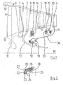
- the stator 2 of the three-stage compressor 1 according to FIG. 1 has an outer one, at least largely rotationally symmetrical housing 3 and three vane rings 4,5 and 6 on.
- the rotor 7 accordingly has three rotor blade rings 8, 9 and 10 on ring-shaped or disk-shaped blade carriers 11, 12 and 13.
- the rotor blade ring 8 forms the most upstream vane grille, the flow direction in compressor 1 accordingly runs from left to right.
- the rotor 7 with components 8 to 10 and 11 to 13 is overhung, i.e. with an over a pivot bearing 18 projecting shaft end 17 is connected.
- the shaft end 17 and the blade carrier 12 an integral unit, these could but also screwed together.
- the pivot bearing 18 is a radial bearing / floating bearing executed, here specifically as a cylindrical roller bearing. Usually with the fixed bearing cooperating further downstream / to the right is not shown since it is not part of the invention.
- the pivot bearing 18 is on the stator side with a frustoconical shape that widens in the downstream direction Carrier 30 connected, which in turn is firmly connected to the rearmost guide vane ring 6 is. This results in a relatively rigid connection of the pivot bearing 18 to the housing 3 of the compressor 1.
- the pivot bearing 18 takes due to its arrangement close to or in the center of gravity of the rotor 7 practically all of it radial loads attacking the latter.
- connection of the blades of the rotor blade rings 8 to 10 with their blade carriers 11 to 13 can be conventional positive or integral, the The tendency is towards integral blisk and bling designs, as shown in FIG. 1.
- the foremost blade carrier 11 forms one with its rotor blade ring 8 metallic blisk (bladed disk) without fiber reinforcement.
- the radial extension of the blade carrier cross section can still be relatively large at this point, i.e. strength technically unproblematic, an MMC construction would not be decisive here Offer advantages.
- the bird strike or FOD problem Form Object Damage
- the blade carrier 12 which has a bling (bladed Ring) in MMC construction. Due to the arrangement radially outside the Pivot bearing 18, the space constrains the radial cross-sectional height of the Blade carrier 12 serious, so that here an MMC construction significant savings in terms of material and weight.
- the most mechanically stressed fiber-reinforced area 14 is shown cross-hatched, the at least an, "endless” reinforcing fiber in a wound arrangement cohesively in the Matrix metal should be integrated.
- the blade carrier contour is dash-dotted for comparison indicated, which would be required without fiber reinforcement.
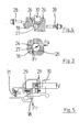
- the connection of the separate ring 20 is shown again enlarged in Figure 2.
- the pressure transmitting seat 25 is designed as a defined press fit, which alone is enough by calculation to axially and the ring 20 to be fixed tangentially to the blade carrier 13.
- the contact area on the ring 20 can be crowned in the sense of a favorable stress distribution (Hertzian pressure) be executed, the contact surface on the blade carrier 13 is cylindrical.
- As an additional Securing is complemented by a form-fitting fixation.
- This is the ring 20 with projections 21 distributed over its circumference, which in corresponding Engage recesses of the blade carrier 13.
- the extensions 21 have axial open grooves 22, the blade carrier 13 radially inward open grooves 23, in the Securing elements 24 in the form of rivets, pins, wires etc.
- the rotor blade ring 8 of the first stage has a so-called Casing treatment, i.e. combined with recirculation channels 32, which is suitable is to improve compressor stability. Such a measure can also be applied to others Compressor stages make sense.
- Figures 3 to 5 illustrate the aspect of overload protection by a predetermined breaking point 19 in the area of the pivot bearing 18.
- ball guides 26 used to deflect radial loads Fr into axial forces Fa under reinforcement. If defined axial forces are exceeded, axial tension screws 28 and release the pivot bearing 18 in the sense of limited radial mobility.
- the guide surfaces of the ball guides 26 are simple in the example shown to be assembled conical and cylindrical surfaces. The strengthening results from the cone angle. Of course, other geometries, e.g. with spherical areas.
- Figure 4 shows the triggered state Load exceeded with broken lag screws 28. It can be seen that the radial Relative displacement (here vertical) also a small axial relative displacement (horizontal here), due to the exit of the balls 27 from the conical surface.
- FIG. 5 shows an alternative design principle for a predetermined breaking point 19.
- Das Rotary bearing 18 is axially on both sides with shear rings in the area of its static outer ring 29 provided which positively in the outer ring of the pivot bearing 18 and engage in the carrier 30 or in elements connected to the latter. If exceeded a defined radial load Fr the shear rings 29 break suddenly without relevant plastic deformation.
- Metallic materials come for the shear rings 29 Materials, ceramic materials or even plastics into consideration, each without or with embedded additives such as particles, fibers etc.. Essential there is a fracture load that can be calculated and reproduced as precisely as possible.
- the triggered state with broken shear ring 29 and radial offset V is on the right the axial center of the rotary bearing 18 is shown.
- the pivot bearing 18 is sealed to the shaft with a brush seal 31, which behaves relatively tolerant of radial shaft deflections.
Landscapes
- Engineering & Computer Science (AREA)
- Mechanical Engineering (AREA)
- General Engineering & Computer Science (AREA)
- Structures Of Non-Positive Displacement Pumps (AREA)
Abstract
Mindestens einer der rotierenden Schaufelträger (11,12,13) ist in MMC-Bauweise, d.h. als zumindest bereichsweise faserverstärktes Metallbauteil ausgeführt, und das den Großteil der am Rotor auftretenden Radiallasten aufnehmende Drehlager (18) weist eine Sollbruchstelle (19) auf, die bei Überschreiten einer definierten Radiallast ein radiales Ausweichen des Rotors mit der Folge eines Anstreifens am Stator (2) ermöglicht.
Description
Claims (10)
- Verdichter in mehrstufiger Axialbauart mit hohem strömungsmechanischem Wirkungsgrad, vorzugsweise zur Verwendung als Niederdruckverdichter einer Fluggasturbine, mit einem fliegend gelagerten, d.h. mit einem von einem Drehlager vorstehenden Wellenende verbundenen Rotor, der mehrere Laufschaufelkränze an miteinander verbundenen, scheiben- und/oder ringförmigen Schaufelträgern umfasst, und mit einer Schaufelanordnung ohne Vorleitgitter, bei der der Laufschaufelkranz der ersten Verdichterstufe das am weitesten stromaufwärts angeordnete Schaufelgitter bildet, dadurch gekennzeichnet, dass mindestens einer (12,13) der rotierenden, scheiben- oder ringförmigen Schaufelträger (11,12,13) in MMC-Bauweise (Metal Matrix Composites), d.h. als zumindest bereichsweise faserverstärktes Metallbauteil ausgeführt ist, und dass das zumindest den Großteil der am Rotor (7) auftretenden Radiallasten aufnehmende Drehlager (18) eine Sollbruchstelle (19) aufweist, die bei Überschreiten einer definierten Radiallast (Fr) ein begrenztes radiales Ausweichen des Rotors (7) mit der Folge eines ggf. bis zum Stillstand drehzahlmindernden Anstreifens am Stator (2) des Verdichters (1) ermöglicht.
- Verdichter nach Anspruch 1, dadurch gekennzeichnet, dass der mindestens eine Schaufelträger (12,13) in MMC-Bauweise im faserverstärkten Bereich (14, 15, 16) eine metallische Matrix, vorzugsweise auf Titanbasis (Ti-Basis), sowie mindestens eine in Wicklungen angeordnete Langfaser aus Siliziumkarbid (SiC) aufweist.
- Verdichter nach Anspruch 1 oder 2, dadurch gekennzeichnet, dass mindestens ein Schaufelträger (12) in MMC-Bauweise als ringförmiges Bauteil, insbesondere mit integraler Beschaufelung als sogenannter Bling (Bladed Ring), mit einem stoffschlüssig integrierten, faserverstärkten Bereich (14) ausgeführt ist.
- Verdichter nach Anspruch 1 oder 2, dadurch gekennzeichnet, dass mindestens ein Schaufelträger (13) in MMC-Bauweise als scheibenförmiges Bauteil, insbesondere mit integraler Beschaufelung als sogenannte Blisk (Bladed Disk), mit zwei symmetrisch zur axialen Scheibenmitte angeordneten, faserverstärkten Bereichen (15, 16) ausgeführt ist, wobei die beiden faserverstärkten Bereiche (15, 16) stoffschlüssig integriert (16) oder reib- und formschlüssig befestigt (15) sind.
- Verdichter nach einem der Ansprüche 1 bis 4, dadurch gekennzeichnet, dass die Sollbruchstelle (19) am Drehlager (18) mit Kugelführungen (26), welche Radiallasten (Fr) unter Verstärkung in Axialkräfte (Fa) umlenken, sowie mit Zugschrauben (28), welche bei Überschreitung einer definierten Axialkraft brechen, ausgeführt ist.
- Verdichter nach einem der Ansprüche 1 bis 4, dadurch gekennzeichnet, dass die Sollbruchstelle (19) am Drehlager (18) mit Scherringen (29), welche bei Überschreitung einer definierten Radiallast brechen, ausgeführt ist.
- Verdichter nach einem der Ansprüche 1 bis 6, dadurch gekennzeichnet, dass das Drehlager (18) als Wälzlager in Radialbauart, insbesondere als Zylinderrollenlager, ausgeführt ist.
- Verdichter nach einem der Ansprüche 1 bis 7, dadurch gekennzeichnet, dass das Drehlager (18) an einem kegelstumpfförmigen, sich in stromabwärtiger Richtung erweiternden sowie stromabwärts des Rotors (7) mit dem Stator (2) des Verdichters (1) verbundenen Träger (30) angeordnet ist.
- Verdichter nach einem der Ansprüche 1 bis 8, dadurch gekennzeichnet, dass 5 das Drehlager (18) zumindest auf einer Seite eine Bürstendichtung (31) aufweist.
- Verdichter nach einem der Ansprüche 1 bis 9, dadurch gekennzeichnet, dass zumindest ein Laufschaufelkranz (8) des Rotors (7) mit einem sogenannten Casing Treatment, d.h. mit einer Vielzahl von gehäuseseitigen Rezirkulationskanälen 0 (32) im Schaufelspitzenbereich, strömungstechnisch kombiniert ist.
Applications Claiming Priority (2)
| Application Number | Priority Date | Filing Date | Title |
|---|---|---|---|
| DE10218459A DE10218459B3 (de) | 2002-04-25 | 2002-04-25 | Verdichter in mehrstufiger Axialbauart |
| DE10218459 | 2002-04-25 |
Publications (3)
| Publication Number | Publication Date |
|---|---|
| EP1357295A2 true EP1357295A2 (de) | 2003-10-29 |
| EP1357295A3 EP1357295A3 (de) | 2004-03-10 |
| EP1357295B1 EP1357295B1 (de) | 2006-08-02 |
Family
ID=28685284
Family Applications (1)
| Application Number | Title | Priority Date | Filing Date |
|---|---|---|---|
| EP03006629A Expired - Lifetime EP1357295B1 (de) | 2002-04-25 | 2003-03-25 | Verdichter in mehrstufiger Axialbauart |
Country Status (5)
| Country | Link |
|---|---|
| US (1) | US7011490B2 (de) |
| EP (1) | EP1357295B1 (de) |
| JP (1) | JP2003328988A (de) |
| CN (1) | CN100339557C (de) |
| DE (2) | DE10218459B3 (de) |
Cited By (6)
| Publication number | Priority date | Publication date | Assignee | Title |
|---|---|---|---|---|
| EP2365186A3 (de) * | 2010-03-04 | 2013-12-25 | Rolls-Royce plc | Verbesserungen im Zusammenhang mit geschichteten Verbundstoffkomponenten |
| EP2824288A1 (de) * | 2013-07-10 | 2015-01-14 | Rolls-Royce Deutschland Ltd & Co KG | Flugtriebwerk |
| EP3012411A1 (de) * | 2014-10-23 | 2016-04-27 | United Technologies Corporation | Integral beschaufelter rotor mit axialem arm und tasche |
| EP3144484A1 (de) * | 2015-08-18 | 2017-03-22 | Rolls-Royce plc | Mittels hebel verstellbare verbindung |
| US10047763B2 (en) | 2015-12-14 | 2018-08-14 | General Electric Company | Rotor assembly for use in a turbofan engine and method of assembling |
| CN114934815A (zh) * | 2022-05-12 | 2022-08-23 | 中国航发四川燃气涡轮研究院 | 一种金属基复合材料箍环式发动机转子叶环结构 |
Families Citing this family (29)
| Publication number | Priority date | Publication date | Assignee | Title |
|---|---|---|---|---|
| FR2841592B1 (fr) * | 2002-06-27 | 2004-09-10 | Snecma Moteurs | Recentrage d'un rotor apres decouplage |
| FR2887919B1 (fr) * | 2005-06-29 | 2010-12-31 | Snecma Moteurs | Rotor de turbomachine comprenant au moins un disque renforce par un anneau composite |
| FR2893093B1 (fr) * | 2005-11-08 | 2008-02-08 | Snecma Sa | Montage d'un anneau composite sur un disque de rotor d'une turbomachine. |
| DE102006011513A1 (de) | 2006-03-10 | 2007-09-13 | Rolls-Royce Deutschland Ltd & Co Kg | Einlaufkonus aus einem Faserverbundwerkstoff für ein Gasturbinentriebwerk und Verfahren zu dessen Herstellung |
| DE102006015838A1 (de) * | 2006-04-03 | 2007-10-04 | Rolls-Royce Deutschland Ltd & Co Kg | Axialkompressor für ein Gasturbinentriebwerk |
| US7625128B2 (en) * | 2006-09-08 | 2009-12-01 | Pratt & Whitney Canada Corp. | Thrust bearing housing for a gas turbine engine |
| US8950069B2 (en) * | 2006-12-29 | 2015-02-10 | Rolls-Royce North American Technologies, Inc. | Integrated compressor vane casing |
| FR2916482B1 (fr) * | 2007-05-25 | 2009-09-04 | Snecma Sa | Systeme de freinage en cas de rupture d'arbre de turbine dans un moteur a turbine a gaz |
| FR2922587B1 (fr) * | 2007-10-22 | 2010-02-26 | Snecma | Roue de turbomachine |
| JP5100370B2 (ja) * | 2007-12-28 | 2012-12-19 | 川崎重工業株式会社 | 推力発生装置 |
| FR2930589B1 (fr) * | 2008-04-24 | 2012-07-06 | Snecma | Prelevement d'air centripete dans un rotor de compresseur d'une turbomachine |
| US8734085B2 (en) * | 2009-08-17 | 2014-05-27 | Pratt & Whitney Canada Corp. | Turbine section architecture for gas turbine engine |
| IT1397328B1 (it) * | 2009-12-11 | 2013-01-10 | Nuovo Pignone Spa | Anelli compositi per montaggio girante-albero. |
| DE102010012228B4 (de) * | 2010-03-19 | 2021-01-14 | Rolls-Royce Deutschland Ltd & Co Kg | Strahltriebwerk mit einer Sollbruchstellenvorrichtung für den Überlastfall |
| US8540482B2 (en) | 2010-06-07 | 2013-09-24 | United Technologies Corporation | Rotor assembly for gas turbine engine |
| JP5479387B2 (ja) * | 2011-02-25 | 2014-04-23 | 三菱重工コンプレッサ株式会社 | 圧縮機およびこの組込方法 |
| US9188062B2 (en) | 2012-08-30 | 2015-11-17 | Mitsubishi Hitachi Power Systems, Ltd. | Gas turbine |
| FR3004227B1 (fr) * | 2013-04-09 | 2016-10-21 | Snecma | Disque de soufflante pour un turboreacteur |
| GB2526609A (en) * | 2014-05-30 | 2015-12-02 | Rolls Royce Plc | Compressor drum |
| US20160047303A1 (en) * | 2014-08-15 | 2016-02-18 | General Electric Company | Power train architectures with mono-type low-loss bearings and low-density materials |
| US20160047309A1 (en) * | 2014-08-15 | 2016-02-18 | General Electric Company | Power train architectures with hybrid-type low-loss bearings and low-density materials |
| US10370971B2 (en) | 2014-11-17 | 2019-08-06 | United Technologies Corporation | Reinforced gas turbine engine rotor disk |
| US9932985B2 (en) | 2015-02-03 | 2018-04-03 | Honeywell International Inc. | Gas turbine engine compressors having optimized stall enhancement feature configurations and methods for the production thereof |
| DE102016219815A1 (de) | 2016-10-12 | 2018-04-12 | Rolls-Royce Deutschland Ltd & Co Kg | Laufschaufelbaugruppe mit ring- oder scheibenförmigem Schaufelträger und radial innenliegender Versteifungsstruktur |
| DE102016219818A1 (de) | 2016-10-12 | 2018-04-12 | Rolls-Royce Deutschland Ltd & Co Kg | Laufschaufelbaugruppe mit ringsegment- oder scheibensegmentförmigem Schaufelträger und radial innenliegender Versteifungsstruktur |
| DE102018205480A1 (de) | 2018-04-11 | 2019-10-17 | Rolls-Royce Deutschland Ltd & Co Kg | Laufschaufelbaugruppe mit einem Sperrelement zur axialen Sicherung eines Versteifungselements einer radial innenliegenden Versteifungsstruktur |
| US11268388B2 (en) * | 2020-04-17 | 2022-03-08 | Raytheon Technologies Corporation | Composite reinforced rotor |
| CN113898610B (zh) * | 2021-10-10 | 2024-08-02 | 中国航发沈阳发动机研究所 | 一种压气机转子轮盘盘心引气结构 |
| EP4717877A1 (de) * | 2023-12-19 | 2026-04-01 | Lilium GmbH | Beschaufelte laufscheibe für einen angetriebenen rotor eines triebwerks einer flugzeugantriebseinheit, antriebseinheit für ein flugzeug und flugzeug |
Family Cites Families (10)
| Publication number | Priority date | Publication date | Assignee | Title |
|---|---|---|---|---|
| GB1170593A (en) | 1967-04-12 | 1969-11-12 | Rolls Royce | Method of making a Bladed Rotor |
| DE69204861T2 (de) * | 1991-01-30 | 1996-05-23 | United Technologies Corp | Ventilatorgehäuse mit Rezirculationskanälen. |
| DE4324755C1 (de) * | 1993-07-23 | 1994-09-22 | Mtu Muenchen Gmbh | Verfahren zur Herstellung faserverstärkter Triebwerkskomponenten |
| GB9317530D0 (en) | 1993-08-21 | 1993-10-06 | Westland Helicopters | Fusible support devices for rotating shafts |
| JP3168865B2 (ja) * | 1995-03-20 | 2001-05-21 | 株式会社日立製作所 | 多段遠心圧縮機用羽根車及びその製造方法 |
| DE19605971C2 (de) | 1996-02-17 | 1998-09-17 | Mtu Muenchen Gmbh | Lageranordnung für Drehkörper |
| GB2320526B (en) * | 1996-12-20 | 2000-09-20 | Rolls Royce Plc | Ducted fan gas turbine engine |
| US6240719B1 (en) * | 1998-12-09 | 2001-06-05 | General Electric Company | Fan decoupler system for a gas turbine engine |
| US6082959A (en) * | 1998-12-22 | 2000-07-04 | United Technologies Corporation | Method and apparatus for supporting a rotatable shaft within a gas turbine engine |
| DE10163951C1 (de) * | 2001-12-22 | 2002-12-19 | Mtu Aero Engines Gmbh | Rotorscheibe aus Metall mit örtlichen Faserverstärkungen |
-
2002
- 2002-04-25 DE DE10218459A patent/DE10218459B3/de not_active Expired - Fee Related
-
2003
- 2003-03-25 EP EP03006629A patent/EP1357295B1/de not_active Expired - Lifetime
- 2003-03-25 DE DE50304419T patent/DE50304419D1/de not_active Expired - Lifetime
- 2003-04-24 JP JP2003120575A patent/JP2003328988A/ja not_active Withdrawn
- 2003-04-25 US US10/423,744 patent/US7011490B2/en not_active Expired - Fee Related
- 2003-04-25 CN CNB031232841A patent/CN100339557C/zh not_active Expired - Fee Related
Cited By (10)
| Publication number | Priority date | Publication date | Assignee | Title |
|---|---|---|---|---|
| EP2365186A3 (de) * | 2010-03-04 | 2013-12-25 | Rolls-Royce plc | Verbesserungen im Zusammenhang mit geschichteten Verbundstoffkomponenten |
| EP2824288A1 (de) * | 2013-07-10 | 2015-01-14 | Rolls-Royce Deutschland Ltd & Co KG | Flugtriebwerk |
| US9797407B2 (en) | 2013-07-10 | 2017-10-24 | Rolls-Royce Deutschland Ltd & Co Kg | Aircraft engine |
| EP3012411A1 (de) * | 2014-10-23 | 2016-04-27 | United Technologies Corporation | Integral beschaufelter rotor mit axialem arm und tasche |
| US10502062B2 (en) | 2014-10-23 | 2019-12-10 | United Technologies Corporation | Integrally bladed rotor having axial arm and pocket |
| EP3144484A1 (de) * | 2015-08-18 | 2017-03-22 | Rolls-Royce plc | Mittels hebel verstellbare verbindung |
| US10513941B2 (en) | 2015-08-18 | 2019-12-24 | Rolls-Royce Plc | Levered joint |
| US10047763B2 (en) | 2015-12-14 | 2018-08-14 | General Electric Company | Rotor assembly for use in a turbofan engine and method of assembling |
| CN114934815A (zh) * | 2022-05-12 | 2022-08-23 | 中国航发四川燃气涡轮研究院 | 一种金属基复合材料箍环式发动机转子叶环结构 |
| CN114934815B (zh) * | 2022-05-12 | 2023-10-31 | 中国航发四川燃气涡轮研究院 | 一种金属基复合材料箍环式发动机转子叶环结构 |
Also Published As
| Publication number | Publication date |
|---|---|
| JP2003328988A (ja) | 2003-11-19 |
| US7011490B2 (en) | 2006-03-14 |
| DE50304419D1 (de) | 2006-09-14 |
| US20030233822A1 (en) | 2003-12-25 |
| CN1453452A (zh) | 2003-11-05 |
| EP1357295A3 (de) | 2004-03-10 |
| EP1357295B1 (de) | 2006-08-02 |
| DE10218459B3 (de) | 2004-01-15 |
| CN100339557C (zh) | 2007-09-26 |
Similar Documents
| Publication | Publication Date | Title |
|---|---|---|
| DE10218459B3 (de) | Verdichter in mehrstufiger Axialbauart | |
| EP2209995B1 (de) | Mehrstufiger turbomolekularpumpen-pumpenrotor | |
| DE69918162T2 (de) | Berstschutzvorrichtung für radialturbinen | |
| WO2008046389A1 (de) | Anordnung zur strömungsbeeinflussung mittels grenzschichtbeeinflussender geometrien | |
| DE10340773A1 (de) | Rotor einer Dampf- oder Gasturbine | |
| EP1843044A1 (de) | Axialkompressor für ein Gasturbinentriebwerk | |
| EP3034788B1 (de) | Kompressorschaufel einer gasturbine | |
| DE102014220317A1 (de) | Fluggasturbinentriebwerk mit Stoßdämpfungselement für Fanschaufelverlust | |
| EP1690011B1 (de) | Rotor für einen verdichter | |
| CH698256B1 (de) | Strömungsmaschine mit radial durchströmtem Verdichterrad. | |
| EP3324002A1 (de) | Dichtungssystem für eine axiale strömungsmaschine und axiale strömungsmaschine | |
| CH698497B1 (de) | Strömungsmaschine mit radial durchströmtem Verdichterrad und mit Halteeinrichtung. | |
| DE10125250C5 (de) | Axialturbine eines Abgastruboladers mit internem Berstschutz | |
| EP3309360B1 (de) | Laufschaufelbaugruppe für ein triebwerk | |
| EP3309359B1 (de) | Laufschaufelbaugruppe für ein triebwerk | |
| WO2011032549A1 (de) | Axial-radial-strömungsmaschine | |
| EP2222962B1 (de) | Deckscheibe für ein geschlossenes laufrad | |
| DE10157576C2 (de) | Drehlagerung mit einer Sollbruchstelle | |
| CH714650B1 (de) | Radialverdichter. | |
| DE10352789B4 (de) | Gasturbine | |
| EP3015652A1 (de) | Laufschaufel für eine Turbine | |
| WO2012110198A1 (de) | Hydraulische strömungsmaschine | |
| EP3246521B1 (de) | Auflauffläche für leitschaufeldeck- und laufschaufelgrundplatte | |
| EP4166754B1 (de) | Rotoranordnung für eine gasturbine mit an rotorsegmenten ausgebildeten, geneigten axialen kontaktflächen, gasturbine und fluggasturbine | |
| CH577108A5 (en) | Turbine blade concave/convex profiles - have constant thickness to certain point whence material thicknes to foot |
Legal Events
| Date | Code | Title | Description |
|---|---|---|---|
| PUAI | Public reference made under article 153(3) epc to a published international application that has entered the european phase |
Free format text: ORIGINAL CODE: 0009012 |
|
| AK | Designated contracting states |
Kind code of ref document: A2 Designated state(s): AT BE BG CH CY CZ DE DK EE ES FI FR GB GR HU IE IT LI LU MC NL PT RO SE SI SK TR |
|
| AX | Request for extension of the european patent |
Extension state: AL LT LV MK |
|
| PUAL | Search report despatched |
Free format text: ORIGINAL CODE: 0009013 |
|
| AK | Designated contracting states |
Kind code of ref document: A3 Designated state(s): AT BE BG CH CY CZ DE DK EE ES FI FR GB GR HU IE IT LI LU MC NL PT RO SE SI SK TR |
|
| AX | Request for extension of the european patent |
Extension state: AL LT LV MK |
|
| RIC1 | Information provided on ipc code assigned before grant |
Ipc: 7F 04D 29/10 B Ipc: 7F 04D 27/02 B Ipc: 7F 04D 29/02 B Ipc: 7F 01D 21/04 B Ipc: 7F 04D 29/04 A |
|
| 17P | Request for examination filed |
Effective date: 20040408 |
|
| AKX | Designation fees paid |
Designated state(s): DE FR GB |
|
| GRAP | Despatch of communication of intention to grant a patent |
Free format text: ORIGINAL CODE: EPIDOSNIGR1 |
|
| GRAS | Grant fee paid |
Free format text: ORIGINAL CODE: EPIDOSNIGR3 |
|
| GRAA | (expected) grant |
Free format text: ORIGINAL CODE: 0009210 |
|
| AK | Designated contracting states |
Kind code of ref document: B1 Designated state(s): DE FR GB |
|
| REG | Reference to a national code |
Ref country code: GB Ref legal event code: FG4D Free format text: NOT ENGLISH |
|
| REF | Corresponds to: |
Ref document number: 50304419 Country of ref document: DE Date of ref document: 20060914 Kind code of ref document: P |
|
| GBT | Gb: translation of ep patent filed (gb section 77(6)(a)/1977) |
Effective date: 20061019 |
|
| ET | Fr: translation filed | ||
| PLBE | No opposition filed within time limit |
Free format text: ORIGINAL CODE: 0009261 |
|
| STAA | Information on the status of an ep patent application or granted ep patent |
Free format text: STATUS: NO OPPOSITION FILED WITHIN TIME LIMIT |
|
| 26N | No opposition filed |
Effective date: 20070503 |
|
| PGFP | Annual fee paid to national office [announced via postgrant information from national office to epo] |
Ref country code: FR Payment date: 20120403 Year of fee payment: 10 |
|
| PGFP | Annual fee paid to national office [announced via postgrant information from national office to epo] |
Ref country code: DE Payment date: 20120323 Year of fee payment: 10 |
|
| PGFP | Annual fee paid to national office [announced via postgrant information from national office to epo] |
Ref country code: GB Payment date: 20120322 Year of fee payment: 10 |
|
| GBPC | Gb: european patent ceased through non-payment of renewal fee |
Effective date: 20130325 |
|
| REG | Reference to a national code |
Ref country code: FR Ref legal event code: ST Effective date: 20131129 |
|
| REG | Reference to a national code |
Ref country code: DE Ref legal event code: R119 Ref document number: 50304419 Country of ref document: DE Effective date: 20131001 |
|
| PG25 | Lapsed in a contracting state [announced via postgrant information from national office to epo] |
Ref country code: DE Free format text: LAPSE BECAUSE OF NON-PAYMENT OF DUE FEES Effective date: 20131001 Ref country code: FR Free format text: LAPSE BECAUSE OF NON-PAYMENT OF DUE FEES Effective date: 20130402 Ref country code: GB Free format text: LAPSE BECAUSE OF NON-PAYMENT OF DUE FEES Effective date: 20130325 |