EP1356987A2 - Variable headrest for seats built-in transversely to the vehicle's direction - Google Patents
Variable headrest for seats built-in transversely to the vehicle's direction Download PDFInfo
- Publication number
- EP1356987A2 EP1356987A2 EP03003643A EP03003643A EP1356987A2 EP 1356987 A2 EP1356987 A2 EP 1356987A2 EP 03003643 A EP03003643 A EP 03003643A EP 03003643 A EP03003643 A EP 03003643A EP 1356987 A2 EP1356987 A2 EP 1356987A2
- Authority
- EP
- European Patent Office
- Prior art keywords
- vehicle
- mounting frame
- headrest
- head
- protected
- Prior art date
- Legal status (The legal status is an assumption and is not a legal conclusion. Google has not performed a legal analysis and makes no representation as to the accuracy of the status listed.)
- Granted
Links
Images


Classifications
-
- B—PERFORMING OPERATIONS; TRANSPORTING
- B60—VEHICLES IN GENERAL
- B60N—SEATS SPECIALLY ADAPTED FOR VEHICLES; VEHICLE PASSENGER ACCOMMODATION NOT OTHERWISE PROVIDED FOR
- B60N2/00—Seats specially adapted for vehicles; Arrangement or mounting of seats in vehicles
- B60N2/80—Head-rests
- B60N2/885—Head-rests provided with side-rests
Definitions
- the invention relates to headrests as head protection for seated People in armored vehicles against the effects of strong ones Accelerations, for example in the event of an impact transporting vehicle on an obstacle with respect to the head and the shark spine of the passenger can occur.
- Restraint devices and headrests are in different Transportation is usually arranged on seats or seating units that installed in the direction of travel or against the direction of travel.
- Seats for the transportation of people can also be transverse to the direction of travel be arranged in the vehicle, particularly in the case of military vehicles.
- the object of the invention is to improve the head protection for the sitting across the direction of travel in a military land vehicle Passengers.
- the advantages of the inventive design of the headrest lie especially in that two functional positions of the in the vehicle built-in support can be taken. If necessary, that's in the side support is folded out when sitting with the passenger. Otherwise, this is essentially when the vehicle is at a standstill or when standing position of the operator to observe or act on Luke, the prop is folded away into the standby position so that it can no space is occupied and an obstacle is avoided, with which the cleared space for better mobility of the crew and other benefits are used. When driving the vehicle in the folded down position Position, the protective effect for the crew fully functions.
- Figure 1 shows the headrest with the three main components, one Mounting frame 10 on a vehicle, not shown is attached, two movable side walls 3 and adaptive Upholstery elements 1 and 7.
- the mounting frame 10 is designed such that the two movable side walls 3 in a laterally double-walled second executed mounting frame 10 are received and stored.
- Mounting frame 10 and side parts 2 are reinforced with webs 11 for the inclusion of a possible special crash load.
- the Sidewalls 3 can go up or down in the direction of 12 can be folded into positions 13 or 14.
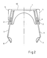
- FIG 2 shows the built-in adaptive cushion element 1, which in Figure 1 is shown removed upwards.
- the sidewalls 3 are with bearing pins 4, 5, each in the double side parts 2 of the mounting frame 10 are mounted, stored.
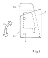
- Figures 3, 4 represent the two functional positions 13, 14 of the Sidewalls 3.
- Bearing and pivot point 5 is in the side part 2 attached bolt around which the side cheek 3 pivots, as well Fixed point and bolt 4, which in a cut window 6th including recess 9 of the side cheek 3 the movement of the Side cheek limited as a stop so that the side cheek 3 in the Position 14 is flush with the front edge 2a of the side part 2.
- the side cheek 3 is folded out to the front and is in this position held by bolts 4 and 9 recess.
- the rotatable side walls 3 are mounted in the pivot point 5 so that they after folding up in position 14 almost flush with the Front edge 2a of the fixed side part 2 of the mounting frame 10 can be fixed, for example, by focusing on part 3. Exact guidance of the side cheeks 3 in the side parts 2 is additionally achieved by the fixed points 4 on the side parts 2.
- the Fixed points 4 can be designed as adjustable bolts, which too enable snapping in the folded-down position 13.
- the Sidewalls 3 are shaped so that they by means of the bend 8 meet ergonomic requirements for use with a hard hat, and also prevent the user's head from crashing out the headrest is turned out.
- In addition to the bend 8 are specially designed side pads 7 on the end faces of the Sidewalls 3 attached to the inside.
- the side walls 3 are largely broken through by means of window 6 in order to an unrestricted view of the user on both sides sure.
- the opening 6 in the side cheeks 3 continues in the Recess 9 continues, the 4 in combination with the guide pin Mobility of the side cheek 3 in the side part 2 ensures.
- the adaptive padding 1 of the headrest is removable and can the respective area of application with regard to, for example, elasticity be adjusted.
- By dividing the headrest into three main ones Components 10, 3, 1 is their manufacture from different materials easy to implement. So the mounting frame 10 made of particularly rigid Material are made, while the side cheeks 3 made of high strength but can consist of defined elastic or deformable material.
- the upholstery 1 can be formed from a quick change system and adjusted in quality and damping.
Abstract
Description
Die Erfindung bezieht sich auf Kopfstützen als Kopfschutz von sitzenden Personen in gepanzerten Fahrzeugen gegen die Wirkung von starken Beschleunigungen, die zum Beispiel bei einem Aufprall des tranportierenden Fahrzeugs auf ein Hindernis bezüglich des Kopfes und der Haiswirbelsäule des Passagiers auftreten können.The invention relates to headrests as head protection for seated People in armored vehicles against the effects of strong ones Accelerations, for example in the event of an impact transporting vehicle on an obstacle with respect to the head and the shark spine of the passenger can occur.
Rückhalteeinrichtungen und Kopfstützen sind in verschiedenen Verkehrsmitteln in der Regel an Sitzen oder Sitzeinheiten angeordnet, die in Fahrtrichtung oder gegen die Fahrtrichtung eingebaut sind.Restraint devices and headrests are in different Transportation is usually arranged on seats or seating units that installed in the direction of travel or against the direction of travel.
Sitze für den Transport von Personen können auch quer zur Fahrtrichtung im Fahrzeug angeordnet sein, insbesondere bei militärischen Fahrzeugen.Seats for the transportation of people can also be transverse to the direction of travel be arranged in the vehicle, particularly in the case of military vehicles.
Bei Queranordung von Sitzen treten bei einem Crash bei Vorwärts- oder Rückwärtsfahrt ebenfalls erhebliche Beschleunigungen auf den Körper des dort sitzenden Besatzungsmitglieds auf, deren Wirkung zu Verletzungen führen kann und die unschädlich gemacht werden müssen.If seats are arranged transversely, a forward or crash occurs Reverse travel also accelerates significantly on the body of the crew member sitting there, their effect to Can cause injuries and must be rendered harmless.
Das alleinige Zurückhalten des Körpers durch ein Gurtsystem führt jedoch nicht zu einer ausreichenden Absicherung der Besatzung, da die Schleuderwirkung auf die Halswirbelsäule bei zurückgehaltenem Rumpf ohne ein angepaßtes Kopfrückhaltesystem sogar noch verstärkt wird. Erschwerend kommt bei Anwendungen in Gefechtsfahrzeugen hinzu, dass der häufig auf dem Kopf getragene Schutzhelm bezüglich Gewicht und Geometrie mit berücksichtigt werden muß. The only retention of the body by a belt system leads however insufficient protection of the crew, since the Slingshot effect on the cervical spine with the trunk restrained is even reinforced without an adapted head restraint system. To make matters worse, applications in combat vehicles that the hard hat often worn on the head in terms of weight and geometry must be taken into account.
Als Beispiel für ein militärisches Fahrzeug wird die DE 19717782 erwähnt, worin eine Kopfstütze an einem in Fahrtrichtung eingebauten Sitz gezeigt wird.DE 19717782 is mentioned as an example of a military vehicle, wherein a headrest is shown on a seat installed in the direction of travel becomes.
Den Stand der üblichen Kopfstützentechnik zeigt DE 20002484, in der eine motorische sich an einen Bediener anpassende Stütze vorgestellt wird. In DE 19738201 wird die Kopfstütze im Fall einer starken Verzögerung automatisch nach vorn an den Kopf geneigt und arretiert.The state of the usual headrest technology is shown in DE 20002484, in the a motorized support that adapts to an operator is presented becomes. In DE 19738201 the headrest is in the case of a strong Deceleration automatically tilted towards the head and locked.
Alle diese Stützen sind nur für den Schutz gegen Beschleunigung in oder gegen die Fahrtrichtung und für entsprechende Sitze ausgelegt. Deshalb wird praktisch nur das freie Schleudern des Kopfes in oder gegen die Fahrtrichtung begrenzt und abgefangen. Seitliches Abfangen des Kopfes wird zum Teil mit kurzen seitlichen Formstücken an der Kopfstütze zu erreichen versucht, im wesentlichen um ein Herausdrehen des Kopfes aus der Kopfstütze zu verhindern. Da das Einbauen von Sitzen quer zur Fahrtrichtung vorwiegend wegen des ungünstigen Verhaltens bei einem Frontalcrash vermieden wird, sind dafür geeignete Kopfstützen ungebräuchlich. Bei militärischen Fahrzeugen läßt sich jedoch die quer zur Fahrtrichtung einsitzende Besatzung oft nicht vermeiden. Bekannt sind auch spezielle Personen-Gurtsysteme aus dem Luftfahrtbereich, die für den Landfahrzeugbereich angepasst und erprobt werden können.All of these supports are only for protection against acceleration in or against the direction of travel and designed for appropriate seats. Therefore practically only the free flinging of the head in or against the Direction of travel limited and intercepted. Side catching of the head is partially closed with short side fittings on the headrest trying to achieve, essentially by unscrewing the head to prevent from the headrest. Since the installation of seats across the Driving direction mainly because of the unfavorable behavior in one Frontal crash is avoided, suitable headrests are suitable for this disuse. In the case of military vehicles, however, this can be done crossways Often avoiding crew sitting in the direction of travel. Are known also special passenger belt systems from the aviation sector, which are for the land vehicle area can be adapted and tested.
Die Nachteile der bekannten Lösungen liegen im Detail darin, dass bei weit nach vorn ragenden Seitenflanken der Kopfstütze die seitliche Sicht des Benutzers stark eingeschränkt wird und der benötigte Bauraum für diese Seitenflanken zu groß ist.The disadvantages of the known solutions lie in the fact that the side view of the headrest that projects far forward the user is severely restricted and the space required for this side flanks is too big.
Aufgabe der Erfindung ist die Verbesserung des Kopfschutzes für den quer zur Fahrtrichtung in einem militärischen Landfahrzeug sitzenden Mitfahrer.The object of the invention is to improve the head protection for the sitting across the direction of travel in a military land vehicle Passengers.
Diese Aufgabe wird erfindungsgemäß durch die kennzeichnenden
Merkmale des Anspruchs 1 gelöst. Weitere Merkmale ergeben sich aus
den Unteransprüchen. This object is achieved by the characterizing
Features of
Erfindungsgemäß wird eine variable Kopfstütze für eine quer zur Fahrtrichtung sitzende Person angeordnet, die den Kopf im Nackenbereich und vor allem nach beiden Seiten und damit in und gegen die Fahrtrichtung abstützt. Da die zu schützende Person auch im angeschnallten Zustand ein gewisses Vorbeugen nach vorn ausführen muß, sind die Seitenflanken der Kopfstütze relativ weit nach vorn auszuführen, damit der Kopf nicht aus der Stütze heraus bewegt wird. Damit die seitliche Sicht nicht zu sehr eingeschränkt wird, sind die Seitenflanken durchbrochen und gestatten die Bedienersicht nach links und rechts totz der weit ausladenden und schützenden Seitenflanken. Außerdem sind die Seitenflanken der Kopfstütze beweglich gelagert, so daß sie bei Nichtgebrauch nach oben in eine Bereitschaftsposition geschwenkt werden können.According to the invention, a variable headrest for a transverse to Arranged seated person who head in Neck area and especially on both sides and thus in and against supports the direction of travel. Since the person to be protected also in do a little forward leaning must, the side flanks of the headrest are relatively far forward so that the head is not moved out of the support. So that the side view is not restricted too much, they are The side edges are broken and allow the operator to see to the left and on the right despite the wide and protective side flanks. In addition, the side flanks of the headrest are movably mounted, so that it is in a standby position when not in use can be pivoted.
Die Vorteile der erfindungsgemässen Ausbildung der Kopfstütze liegen insbesondere darin, daß zwei Funktionsstellungen von der im Fahrzeug eingebauten Stütze eingenommen werden können. Bei Bedarf, das ist im wesentlichen bei Mitfahrt im Sitzen, ist die seitliche Stütze herausgeklappt. Ansonsten, das ist im wesentlichen im Stillstand des Fahrzeugs oder bei stehender Position des Bedieners zum Beobachten oder Wirken über Luke, wird die Stütze weggeklappt in die Bereitschaftsposition, so daß sie keinen Einbauraum belegt und ein Hindernis vermieden wird, womit der freigemachte Raum für eine bessere Beweglichkeit der Besatzung und andere Vorteile genutzt wird. Bei Fahrzeugfahrt in der vorgeklappten Stellung tritt die Schutzwirkung für die Besatzung voll in Funktion.The advantages of the inventive design of the headrest lie especially in that two functional positions of the in the vehicle built-in support can be taken. If necessary, that's in the side support is folded out when sitting with the passenger. Otherwise, this is essentially when the vehicle is at a standstill or when standing position of the operator to observe or act on Luke, the prop is folded away into the standby position so that it can no space is occupied and an obstacle is avoided, with which the cleared space for better mobility of the crew and other benefits are used. When driving the vehicle in the folded down position Position, the protective effect for the crew fully functions.
Wegen der offenen Bauweise der Kopfstützen als Rahmen-Kopfstützen und der durchbrochenen Seitenflanken wird die seitliche Sichtbehinderung minimiert und das psychologische Wohlbefinden der Besatzung verbessert.Because of the open design of the headrests as frame headrests and the openwork side flanks become the side view obstruction minimized and the psychological well-being of the crew improved.
Ausführungsbeispiele der Erfindung sind in den Zeichnungen schematisch dargestellt und werden im folgenden näher beschrieben. Es zeigen:
- Figur 1:
- eine Gesamtansicht der Kopfstütze
- Figur 2:
- eine Draufsicht der Kopfstütze
- Figur 3:
- eine Seitenansicht der Kopfstütze
- Figur 4:
- eine Seitenansicht der Kopfstütze Bereitschaftsstellung
- Figure 1:
- an overall view of the headrest
- Figure 2:
- a top view of the headrest
- Figure 3:
- a side view of the headrest
- Figure 4:
- a side view of the headrest standby
Figur 1 zeigt die Kopfstütze mit den drei Hauptbauelementen, einem
Montagerahmen 10, der an einem nicht näher dargestellten Fahrzeug
befestigt wird, zwei beweglichen Seitenwangen 3 und adaptiven
Polsterelementen 1 und 7. Der Montagerahmen 10 ist so ausgebildet, daß
die zwei beweglichen Seitenwangen 3 in einem seitlich doppelwandig 2
ausgeführten Montagerahmen 10 aufgenommen und gelagert werden.
Montagerahmen 10 und Seitenteile 2 werden mit Stegen 11 verstärkt für
die Aufnahme einer möglichen speziellen Crashbelastung. Die
Seitenwangen 3 können in Richtung 12 nach oben oder nach unten
geklappt werden in die Stellungen 13 oder 14.Figure 1 shows the headrest with the three main components, one
Figur 2 zeigt das eingebaute adaptive Polsterelement 1, welches in Figur
1 nach oben herausgenommen dargestellt ist. Die Seitenwangen 3
werden mit Lagerstiften 4, 5, die jeweils in den doppelten Seitenteilen 2
des Montagerahmens 10 befestigt sind, gelagert.Figure 2 shows the built-in
Die Figuren 3, 4 stellen die beiden Funktionsstellungen 13, 14 der
Seitenwangen 3 dar. Lager- und Drehpunkt 5 ist ein im Seitenteil 2
befestigter Bolzen, um den die Seitenwange 3 schwenkt, ebenso wie
Fixpunkt und Bolzen 4, welcher in einem ausgeschnittenen Fenster 6
einschliesslich Aussparung 9 der Seitenwange 3 die Bewegung der
Seitenwange als Anschlag so begrenzt, daß die Seitenwange 3 in der
Stellung 14 mit der Vorderkante 2a des Seitenteils 2 bündig liegt. In
Stellung 13 ist die Seitenwange 3 nach vorn herausgeklappt und wird in
dieser Lage durch Bolzen 4 und Aussparung 9 festgehalten.Figures 3, 4 represent the two functional positions 13, 14 of the
Die drehbaren Seitenwangen 3 sind im Drehpunkt 5 so gelagert, daß sie
nach dem Hochklappen in Stellung 14 annähernd bündig mit der
Vorderkante 2a des feststehenden Seitenteils 2 des Montagerahmens 10
fixiert werden, zum Beispiel mittels Schwerpunktausbildung von Teil 3.
Eine exakte Führung der Seitenwangen 3 in den Seitenteilen 2 wird
zusätzlich durch die Fixpunkte 4 auf den Seitenteilen 2 erreicht. Die
Fixpunkte 4 können als einstellbare Bolzen ausgeführt werden, die auch
ein Einrasten in der heruntergeklappten Stellung 13 ermöglichen. Die
Seitenwangen 3 sind so ausgeformt, daß sie mittels Abwinkelung 8 die
ergonomischen Anforderungen für die Benutzung mit Schutzhelm erfüllen,
und auch verhindern, daß der Kopf des Benutzers bei einem Crash aus
der Kopfstütze heraus gedreht wird. Ergänzend zu der Abwinkelung 8
werden speziell ausgebildete Seitenpolster 7 an den Stirnseiten der
Seitenwangen 3 auf den Innenseiten angebracht.The
Die Seitenwangen 3 sind mittels Fenster 6 großflächig durchbrochen, um
eine möglichst uneingeschränkte Sicht des Benutzers zu beiden Seiten
sicherzustellen. Der Durchbruch 6 in den Seitenwangen 3 setzt sich in der
Aussparung 9 fort, die in Kombination mit dem Führungsbolzen 4 die
Beweglichkeit der Seitenwange 3 im Seitenteil 2 sichert.The
Die adaptive Polsterung 1 der Kopfstütze ist herausnehmbar und kann
dem jeweiligen Einsatzbereich hinsichtlich zum Beispiel Elastizität
angepaßt werden. Durch die Aufteilung der Kopfstütze in drei wesentliche
Bauelemente 10, 3, 1 ist deren Fertigung aus unterschiedllichem Material
leicht realisierbar. So kann der Montagerahmen 10 aus besonders steifem
Material gefertigt werden, während die Seitenwangen 3 aus hochfestem
aber definiert elastischem oder verformbarem Material bestehen können.
Die Polsterung 1 kann aus einem Schnellwechselsystem gebildet werden
und in Qualität und Dämpfung angepasst werden. The
- 11
- Polsterelementcushion element
- 22
- Seitenteilside panel
- 2a2a
- Vorderkanteleading edge
- 33
- Seitenwagensidecar
- 44
- Lagerstiftbearing pin
- 55
- Lagerstiftbearing pin
- 66
- Fenster / DurchbruchWindow / breakthrough
- 77
- Polsterelementcushion element
- 88th
- Abwinkelungangulation
- 99
- Aussparungrecess
- 1010
- Montagerahmenmounting frame
- 1111
- Stegweb
- 1212
- Richtungdirection
- 1313
- Stellungposition
- 1414
- Stellungposition
Claims (10)
dadurch gekennzeichnet, daß eine Kopfstütze aus einem am Fahrzeug in Kopfhöhe befestigten Montagerahmen (10), zwei beweglichen Seitenwangen (3) und adaptiver Polsterung (1, 7) besteht und die Seitenwangen im Montagerahmen (10) befestigt sind und mittels Lagerungen (4, 5) aus der Funktionsstellung ausgeklappt (13) in eine Bereitschaftsstellung hochgeschwenkt (14) und umgekehrt geklappt werden können.Device for protecting against the effects of strong acceleration on the crew of an armored vehicle, in particular in the event of an impact of the vehicle as a result of an accident, and in particular for protecting the head and cervical spine of the operators sitting in the vehicle transverse to the direction of travel by attaching protective elements for the head of the vehicle to be protected person above and assigned to a vehicle-fixed seat
characterized in that a headrest consists of a mounting frame (10) attached to the vehicle at head height, two movable side bolsters (3) and adaptive padding (1, 7) and the side bolsters are fastened in the mounting frame (10) and by means of bearings (4, 5 ) from the functional position (13) can be swung up into a standby position (14) and can be folded vice versa.
dadurch gekennzeichnet, daß je eine Seitenwange (3) mittig in doppelwandig ausgeführten Auskragungen (2) an beiden Seiten eines Montagerahmens (10) verschieblich und um 90 Grad drehbar mittels Lagerpunkten (5) und einem arretierenden Anschlag (4) gelagert ist.Device according to claim 1
characterized in that one side cheek (3) is mounted centrally in double-walled projections (2) on both sides of a mounting frame (10) and is rotatable and rotatable by 90 degrees by means of bearing points (5) and a locking stop (4).
dadurch gekennzeichnet, daß die Seitenwange (3) mittels eines Durchbruchs (6) und einer damit zusammenhängenden Aussparung (9) sowie mittels Bolzen (4, 5), welche in den doppelwandigen Auskragungen (2) des Montagerahmens (10) befestigt sind und welche durch den Durchbruch (6) ragen, verschiebbar und drehbar gelagert ist. Apparatus according to claims 1 and 2
characterized in that the side cheek (3) by means of an opening (6) and an associated recess (9) and by means of bolts (4, 5) which are fastened in the double-walled projections (2) of the mounting frame (10) and which by protrude the opening (6), is slidably and rotatably mounted.
dadurch gekennzeichnet, daß schwenkbare Seitenwangen (3) mit einem Durchbruch (6) als Fenster für die Seitensicht des jeweils dahinterpositionierten Auges einer zu schützenden Person versehen sind.Device according to one of the above claims
characterized in that pivotable side cheeks (3) are provided with an opening (6) as a window for the side view of the eye of a person to be protected, which is positioned behind them.
dadurch gekennzeichnet, daß Stege (11) am Montagerahmen (10) angebracht sind, um den Aufbau gegen auftretende Crash-Beschleunigungen ausreichend zu verstärken.Device according to one of the above claims
characterized in that webs (11) are attached to the mounting frame (10) in order to sufficiently reinforce the structure against occurring crash accelerations.
dadurch gekennzeichnet, daß leicht austauschbare Polsterlemente (1, 7) am Montagerahmen (10) und an der Seitenwange (7) angebracht sind, welche die Kopfstütze gegen den Kopf der zu schützenden Person abpolstern und je nach Einsatzfall und aus hygienischen Gründen ausgetauscht werden.Device according to one of the above claims
characterized in that easily replaceable cushion elements (1, 7) are attached to the mounting frame (10) and on the side cheek (7), which cushion the headrest against the head of the person to be protected and are replaced depending on the application and for hygienic reasons.
dadurch gekennzeichnet, daß die Seitenwangen (3) mittels einer entsperrbaren Verriegelung in der Funktionsstellung ausgeschwenkt (13) gehalten werden, welche nur mittels eines Auslösemechanismus entsperrt werden kann vom Benutzer, sofern die Stellung ausgeschwenkt vorlaufend oder bei Fahrtantritt eingenommen wurde.Device according to one of the above claims
characterized in that the side cheeks (3) are pivoted out in the functional position by means of an unlockable lock (13), which can only be unlocked by means of a release mechanism by the user, provided that the position has been swung out in advance or at the start of the journey.
dadurch gekennzeichnet, daß die Stellung der Seitenwangen (3) mittels eines Lagesensors überwacht und als Meldung an den Fahrzeugführer mitgeteilt wird zur Überwachung insbesondere in Verbindung mit einem Sitzkontakt für die Meldung eines belegten Sitzplatzes. Device according to one of the above claims
characterized in that the position of the side cheeks (3) is monitored by means of a position sensor and is communicated to the vehicle driver as a message for monitoring, in particular in connection with a seat contact for reporting an occupied seat.
dadurch gekennzeichnet, daß die Seitenwangen (3) im vorderen Bereich so ausgeformt sind, daß sie mittels Abwinkelung (8) und Abpolsterung (7) die ergonomischen Anforderungen für die Benutzung mit Schutzhelm ohne Behinderung erfüllen und gleichzeitig verhindern, dass der Kopf des Benutzers bei einem Crash aus der Kopfstütze herausgedreht wird.Device according to one of the above claims
characterized in that the side cheeks (3) are shaped in the front area so that they meet the ergonomic requirements for use with a protective helmet without disability by means of angled portion (8) and padding (7) and at the same time prevent the user's head from being in one Crash is turned out of the headrest.
dadurch gekennzeichnet, daß durch den modularen Aufbau der Kopfstütze die Materialien der Teile (1, 3, 7, 10) so gewählt werden können, daß sie im Einzelnen bezüglich der Forderungen nach geringem Gewicht, hoher Steifigkeit und Festigkeit oder gezielt bezüglich der stoßverringernden Nachgiebigkeit geeignet sind.Device according to one of the above claims
characterized in that the modular structure of the headrest enables the materials of the parts (1, 3, 7, 10) to be selected such that they are suitable in particular with regard to the demands for low weight, high rigidity and strength or specifically with regard to the impact-reducing flexibility are.
Applications Claiming Priority (2)
| Application Number | Priority Date | Filing Date | Title |
|---|---|---|---|
| DE10218961A DE10218961B3 (en) | 2002-04-27 | 2002-04-27 | Variable headrest for seats installed transversely to the direction of travel |
| DE10218961 | 2002-04-27 |
Publications (3)
| Publication Number | Publication Date |
|---|---|
| EP1356987A2 true EP1356987A2 (en) | 2003-10-29 |
| EP1356987A3 EP1356987A3 (en) | 2004-01-21 |
| EP1356987B1 EP1356987B1 (en) | 2005-07-13 |
Family
ID=7714453
Family Applications (1)
| Application Number | Title | Priority Date | Filing Date |
|---|---|---|---|
| EP03003643A Expired - Lifetime EP1356987B1 (en) | 2002-04-27 | 2003-02-18 | Variable headrest for seats built-in transversely to the vehicle's direction |
Country Status (5)
| Country | Link |
|---|---|
| EP (1) | EP1356987B1 (en) |
| AT (1) | ATE299448T1 (en) |
| DE (2) | DE10218961B3 (en) |
| ES (1) | ES2242908T3 (en) |
| NO (1) | NO20030806L (en) |
Cited By (8)
| Publication number | Priority date | Publication date | Assignee | Title |
|---|---|---|---|---|
| WO2005087537A1 (en) * | 2004-03-13 | 2005-09-22 | Britax Excelsior Limited | Safety seat |
| FR2875190A1 (en) * | 2004-09-13 | 2006-03-17 | Cera | Headrest for motor vehicle seat, has wing with support side opposite to opposite side of cushion when in inactive position in which rotation axis is disposed in lateral part of headrest by forming preset angle with support side of cushion |
| FR2884464A1 (en) * | 2005-04-19 | 2006-10-20 | Faurecia Sieges Automobile | Motor vehicle seat safety system comprises part of seat back that deploys to protect occupant when crash is imminent |
| FR2885853A1 (en) * | 2005-05-23 | 2006-11-24 | Renault Sas | Motor vehicle seat head-rest, has lateral cushion, with handles, sliding between storage and use positions where it is placed respectively inside and outside main cushion, and pivoting around longitudinal axis to occupy several positions |
| GB2432784A (en) * | 2005-12-03 | 2007-06-06 | Nissan Technical Ct Europ Ltd | Adjustable head rest |
| FR2917344A1 (en) * | 2007-06-15 | 2008-12-19 | Airbus France Sas | MULTIMODAL HEADREST FOR VEHICLE SEAT |
| CN104192032A (en) * | 2014-09-24 | 2014-12-10 | 上海华迎汽车零部件有限公司 | Automobile headrest |
| US10518682B1 (en) * | 2018-09-06 | 2019-12-31 | GM Global Technology Operations LLC | Lateral head support for a vehicle passenger seat |
Families Citing this family (3)
| Publication number | Priority date | Publication date | Assignee | Title |
|---|---|---|---|---|
| GB0405716D0 (en) * | 2004-03-13 | 2004-04-21 | Britax Excelsior | Safety seat |
| DE102007025208B4 (en) * | 2006-12-06 | 2016-02-04 | Rheinmetall Landsysteme Gmbh | Headrest, in particular for armored vehicles |
| DE102017211594A1 (en) * | 2017-07-07 | 2019-01-10 | Bayerische Motoren Werke Aktiengesellschaft | motor vehicle |
Citations (3)
| Publication number | Priority date | Publication date | Assignee | Title |
|---|---|---|---|---|
| DE19738201A1 (en) | 1996-10-16 | 1998-04-23 | Grammer Ag | Motor vehicle front seat with headrest |
| DE19717782A1 (en) | 1997-04-26 | 1998-11-05 | Wegmann & Co Gmbh | Seat unit in military vehicle, especially observation or reconnaissance car |
| DE20002484U1 (en) | 2000-02-11 | 2000-11-16 | Grammer Automotive Gmbh | Headrests for vehicle seats |
Family Cites Families (15)
| Publication number | Priority date | Publication date | Assignee | Title |
|---|---|---|---|---|
| GB300391A (en) * | 1927-11-12 | 1928-11-15 | Drysdale & Co Ltd | Improvements in apparatus for de-aerating lubricating oil |
| US3851919A (en) * | 1973-08-01 | 1974-12-03 | J Nagy | Automobile headrest |
| DE3039934C2 (en) * | 1980-10-23 | 1983-11-03 | Audi Nsu Auto Union Ag, 7107 Neckarsulm | Headrest for automobile seats |
| JPS57158128A (en) * | 1981-03-26 | 1982-09-29 | Nissan Motor Co Ltd | Headrest for car |
| DE8333127U1 (en) * | 1983-11-18 | 1984-03-01 | Breitenbach, Dieter, 6000 Frankfurt | Device for protecting the head of vehicle occupants in the event of an accident |
| DE3841024C1 (en) * | 1988-12-06 | 1989-10-05 | Siegfried 3012 Langenhagen De Maisenhaelder | |
| DE8810569U1 (en) * | 1988-08-20 | 1988-12-29 | Maisenhaelder, Siegfried, 3012 Langenhagen, De | |
| IT220461Z2 (en) * | 1990-06-29 | 1993-09-22 | Fiat Auto Spa | SEAT FOR A VEHICLE. |
| DE4116759A1 (en) * | 1991-05-23 | 1992-11-26 | Bayerische Motoren Werke Ag | Padded support for head of rear set car passenger - uses upholstered pad attached to side of rear pillar |
| US5370446A (en) * | 1993-12-10 | 1994-12-06 | Bancod; Ludovico E. | Headrest with side supports |
| DE19653516A1 (en) * | 1995-12-23 | 1997-06-26 | Volkswagen Ag | Headrest with side wings, fitted to vehicle seat |
| FR2768093B1 (en) * | 1997-09-05 | 1999-11-26 | Gilbert Leon Maurice Calvayrac | ARTICULATED MECHANISM PROVIDING THE LATERAL HOLDING OF THE HEAD OF A PASSENGER OF A TRANSPORT VEHICLE |
| FR2779394B1 (en) * | 1998-06-03 | 2000-06-30 | Luc Raymond Marie Morin | RETRACTABLE TEMP SUPPORT, TWO POSITIONS: AWAKE AND SLEEP, FOR PASSENGER SEAT |
| DE29811734U1 (en) * | 1998-07-01 | 1998-10-01 | Breed Automotive Tech | Restraint device for one person in the vehicle |
| DE20016359U1 (en) * | 2000-09-21 | 2001-11-08 | Ditom Verwaltungs Gmbh | Side headrest on vehicle seats |
-
2002
- 2002-04-27 DE DE10218961A patent/DE10218961B3/en not_active Expired - Fee Related
-
2003
- 2003-02-18 DE DE50300747T patent/DE50300747D1/en not_active Expired - Fee Related
- 2003-02-18 ES ES03003643T patent/ES2242908T3/en not_active Expired - Lifetime
- 2003-02-18 EP EP03003643A patent/EP1356987B1/en not_active Expired - Lifetime
- 2003-02-18 AT AT03003643T patent/ATE299448T1/en not_active IP Right Cessation
- 2003-02-21 NO NO20030806A patent/NO20030806L/en not_active Application Discontinuation
Patent Citations (3)
| Publication number | Priority date | Publication date | Assignee | Title |
|---|---|---|---|---|
| DE19738201A1 (en) | 1996-10-16 | 1998-04-23 | Grammer Ag | Motor vehicle front seat with headrest |
| DE19717782A1 (en) | 1997-04-26 | 1998-11-05 | Wegmann & Co Gmbh | Seat unit in military vehicle, especially observation or reconnaissance car |
| DE20002484U1 (en) | 2000-02-11 | 2000-11-16 | Grammer Automotive Gmbh | Headrests for vehicle seats |
Cited By (14)
| Publication number | Priority date | Publication date | Assignee | Title |
|---|---|---|---|---|
| AU2005221394B2 (en) * | 2004-03-13 | 2011-06-02 | Britax Excelsior Limited | Safety seat |
| WO2005087537A1 (en) * | 2004-03-13 | 2005-09-22 | Britax Excelsior Limited | Safety seat |
| US7506926B2 (en) | 2004-03-13 | 2009-03-24 | Britax Excelsior Limited | Safety seat |
| FR2875190A1 (en) * | 2004-09-13 | 2006-03-17 | Cera | Headrest for motor vehicle seat, has wing with support side opposite to opposite side of cushion when in inactive position in which rotation axis is disposed in lateral part of headrest by forming preset angle with support side of cushion |
| FR2884464A1 (en) * | 2005-04-19 | 2006-10-20 | Faurecia Sieges Automobile | Motor vehicle seat safety system comprises part of seat back that deploys to protect occupant when crash is imminent |
| FR2885853A1 (en) * | 2005-05-23 | 2006-11-24 | Renault Sas | Motor vehicle seat head-rest, has lateral cushion, with handles, sliding between storage and use positions where it is placed respectively inside and outside main cushion, and pivoting around longitudinal axis to occupy several positions |
| GB2432784A (en) * | 2005-12-03 | 2007-06-06 | Nissan Technical Ct Europ Ltd | Adjustable head rest |
| GB2432784B (en) * | 2005-12-03 | 2009-11-04 | Nissan Technical Ct Europ Ltd | Head rest |
| FR2917344A1 (en) * | 2007-06-15 | 2008-12-19 | Airbus France Sas | MULTIMODAL HEADREST FOR VEHICLE SEAT |
| US8342606B2 (en) | 2007-06-15 | 2013-01-01 | Airbus Operations Sas | Multimodal headrest for vehicle seat |
| WO2009004211A3 (en) * | 2007-06-15 | 2010-01-14 | AIRBUS OPERATIONS (Société par actions simplifiée) | Multimodal headrest for vehicle seat |
| CN104192032A (en) * | 2014-09-24 | 2014-12-10 | 上海华迎汽车零部件有限公司 | Automobile headrest |
| CN104192032B (en) * | 2014-09-24 | 2016-08-10 | 上海华迎汽车零部件有限公司 | A kind of automotive headrest |
| US10518682B1 (en) * | 2018-09-06 | 2019-12-31 | GM Global Technology Operations LLC | Lateral head support for a vehicle passenger seat |
Also Published As
| Publication number | Publication date |
|---|---|
| NO20030806L (en) | 2003-10-28 |
| DE10218961B3 (en) | 2004-01-22 |
| ES2242908T3 (en) | 2005-11-16 |
| DE50300747D1 (en) | 2005-08-18 |
| ATE299448T1 (en) | 2005-07-15 |
| EP1356987A3 (en) | 2004-01-21 |
| NO20030806D0 (en) | 2003-02-21 |
| EP1356987B1 (en) | 2005-07-13 |
Similar Documents
| Publication | Publication Date | Title |
|---|---|---|
| DE69732514T2 (en) | Seat assembly with a system for protecting the head | |
| DE1555142B2 (en) | HEAD PROTECTION FOR VEHICLE OCCUPANTS | |
| EP1717098B1 (en) | Passenger seat for public transportation vehicle | |
| EP1777100B1 (en) | Backrest system | |
| DE10218961B3 (en) | Variable headrest for seats installed transversely to the direction of travel | |
| DE1655057A1 (en) | Seat, especially for motor vehicles | |
| EP1132292B1 (en) | Passenger seat with safety means | |
| WO2017157838A1 (en) | Vehicle having a central seat position | |
| EP2910412B1 (en) | Seat, in particular passenger seat | |
| EP1394003B1 (en) | Restraining system | |
| DE69814836T2 (en) | REINFORCEMENT ELEMENTS FOR A VEHICLE | |
| DE102008003720A1 (en) | Vehicle seat i.e. passenger seat, has seat part and backrest pivotable together around axle running transverse to driving direction, where axle is arranged within connecting area of seat part and backrest | |
| DE19749780A1 (en) | Vehicle safety belt system for automobile train or aircraft | |
| DE2407178A1 (en) | SAFETY DEVICE FOR VEHICLES | |
| DE10107265A1 (en) | Passenger protection and baggage securing device has rear seat bank backrest divided in dividing plane, with one part able to be folded for extra baggage space | |
| EP1190892B1 (en) | Motor vehicle seat | |
| DE2428285A1 (en) | Securing system for vehicle occupant - has rigid fastener loops to embrace shoulders and thighs on each side | |
| DE102013218595A1 (en) | Headrest with holding device for a side head rest, side head rest and retrofit kit with same as well as seat | |
| AT406949B (en) | SAFETY DEVICE FOR MOTOR VEHICLES | |
| DE102017209400B4 (en) | Headrest, seat with a headrest and vehicle with a vehicle seat | |
| EP3597161B1 (en) | Device for securing a wheelchair | |
| DE19603105C1 (en) | Vehicle seat headrest support device activated upon impact | |
| DE102022000640A1 (en) | vehicle seat | |
| DE1958460A1 (en) | Device for protecting passengers inside a vehicle | |
| DE102021206294A1 (en) | Standing niche for vehicles to accommodate exactly one occupant aligned transversely to the direction of travel |
Legal Events
| Date | Code | Title | Description |
|---|---|---|---|
| PUAI | Public reference made under article 153(3) epc to a published international application that has entered the european phase |
Free format text: ORIGINAL CODE: 0009012 |
|
| AK | Designated contracting states |
Kind code of ref document: A2 Designated state(s): AT BE BG CH CY CZ DE DK EE ES FI FR GB GR HU IE IT LI LU MC NL PT SE SI SK TR |
|
| AX | Request for extension of the european patent |
Extension state: AL LT LV MK RO |
|
| PUAL | Search report despatched |
Free format text: ORIGINAL CODE: 0009013 |
|
| AK | Designated contracting states |
Kind code of ref document: A3 Designated state(s): AT BE BG CH CY CZ DE DK EE ES FI FR GB GR HU IE IT LI LU MC NL PT SE SI SK TR |
|
| AX | Request for extension of the european patent |
Extension state: AL LT LV MK RO |
|
| RIC1 | Information provided on ipc code assigned before grant |
Ipc: 7B 60N 2/48 A Ipc: 7B 60N 2/24 B |
|
| 17P | Request for examination filed |
Effective date: 20031210 |
|
| 17Q | First examination report despatched |
Effective date: 20040312 |
|
| AKX | Designation fees paid |
Designated state(s): AT BE BG CH CY CZ DE DK EE ES FI FR GB GR HU IE IT LI LU MC NL PT SE SI SK TR |
|
| GRAP | Despatch of communication of intention to grant a patent |
Free format text: ORIGINAL CODE: EPIDOSNIGR1 |
|
| GRAS | Grant fee paid |
Free format text: ORIGINAL CODE: EPIDOSNIGR3 |
|
| GRAA | (expected) grant |
Free format text: ORIGINAL CODE: 0009210 |
|
| AK | Designated contracting states |
Kind code of ref document: B1 Designated state(s): AT BE BG CH CY CZ DE DK EE ES FI FR GB GR HU IE IT LI LU MC NL PT SE SI SK TR |
|
| PG25 | Lapsed in a contracting state [announced via postgrant information from national office to epo] |
Ref country code: IT Free format text: LAPSE BECAUSE OF FAILURE TO SUBMIT A TRANSLATION OF THE DESCRIPTION OR TO PAY THE FEE WITHIN THE PRESCRIBED TIME-LIMIT;WARNING: LAPSES OF ITALIAN PATENTS WITH EFFECTIVE DATE BEFORE 2007 MAY HAVE OCCURRED AT ANY TIME BEFORE 2007. THE CORRECT EFFECTIVE DATE MAY BE DIFFERENT FROM THE ONE RECORDED. Effective date: 20050713 Ref country code: SI Free format text: LAPSE BECAUSE OF FAILURE TO SUBMIT A TRANSLATION OF THE DESCRIPTION OR TO PAY THE FEE WITHIN THE PRESCRIBED TIME-LIMIT Effective date: 20050713 Ref country code: SK Free format text: LAPSE BECAUSE OF FAILURE TO SUBMIT A TRANSLATION OF THE DESCRIPTION OR TO PAY THE FEE WITHIN THE PRESCRIBED TIME-LIMIT Effective date: 20050713 Ref country code: EE Free format text: LAPSE BECAUSE OF FAILURE TO SUBMIT A TRANSLATION OF THE DESCRIPTION OR TO PAY THE FEE WITHIN THE PRESCRIBED TIME-LIMIT Effective date: 20050713 Ref country code: IE Free format text: LAPSE BECAUSE OF FAILURE TO SUBMIT A TRANSLATION OF THE DESCRIPTION OR TO PAY THE FEE WITHIN THE PRESCRIBED TIME-LIMIT Effective date: 20050713 Ref country code: CZ Free format text: LAPSE BECAUSE OF FAILURE TO SUBMIT A TRANSLATION OF THE DESCRIPTION OR TO PAY THE FEE WITHIN THE PRESCRIBED TIME-LIMIT Effective date: 20050713 |
|
| REG | Reference to a national code |
Ref country code: GB Ref legal event code: FG4D Free format text: NOT ENGLISH |
|
| REG | Reference to a national code |
Ref country code: CH Ref legal event code: EP |
|
| GBT | Gb: translation of ep patent filed (gb section 77(6)(a)/1977) |
Effective date: 20050713 |
|
| REG | Reference to a national code |
Ref country code: IE Ref legal event code: FG4D Free format text: LANGUAGE OF EP DOCUMENT: GERMAN |
|
| REF | Corresponds to: |
Ref document number: 50300747 Country of ref document: DE Date of ref document: 20050818 Kind code of ref document: P |
|
| REG | Reference to a national code |
Ref country code: CH Ref legal event code: NV Representative=s name: OK PAT AG PATENTE MARKEN LIZENZEN |
|
| PG25 | Lapsed in a contracting state [announced via postgrant information from national office to epo] |
Ref country code: BG Free format text: LAPSE BECAUSE OF FAILURE TO SUBMIT A TRANSLATION OF THE DESCRIPTION OR TO PAY THE FEE WITHIN THE PRESCRIBED TIME-LIMIT Effective date: 20051013 Ref country code: SE Free format text: LAPSE BECAUSE OF FAILURE TO SUBMIT A TRANSLATION OF THE DESCRIPTION OR TO PAY THE FEE WITHIN THE PRESCRIBED TIME-LIMIT Effective date: 20051013 Ref country code: DK Free format text: LAPSE BECAUSE OF FAILURE TO SUBMIT A TRANSLATION OF THE DESCRIPTION OR TO PAY THE FEE WITHIN THE PRESCRIBED TIME-LIMIT Effective date: 20051013 |
|
| REG | Reference to a national code |
Ref country code: GR Ref legal event code: EP Ref document number: 20050402895 Country of ref document: GR |
|
| RAP2 | Party data changed (patent owner data changed or rights of a patent transferred) |
Owner name: RHEINMETALL LANDSYSTEME GMBH |
|
| REG | Reference to a national code |
Ref country code: ES Ref legal event code: FG2A Ref document number: 2242908 Country of ref document: ES Kind code of ref document: T3 |
|
| PG25 | Lapsed in a contracting state [announced via postgrant information from national office to epo] |
Ref country code: PT Free format text: LAPSE BECAUSE OF FAILURE TO SUBMIT A TRANSLATION OF THE DESCRIPTION OR TO PAY THE FEE WITHIN THE PRESCRIBED TIME-LIMIT Effective date: 20051219 |
|
| NLT2 | Nl: modifications (of names), taken from the european patent patent bulletin |
Owner name: RHEINMETALL LANDSYSTEME GMBH Effective date: 20051109 |
|
| PG25 | Lapsed in a contracting state [announced via postgrant information from national office to epo] |
Ref country code: HU Free format text: LAPSE BECAUSE OF FAILURE TO SUBMIT A TRANSLATION OF THE DESCRIPTION OR TO PAY THE FEE WITHIN THE PRESCRIBED TIME-LIMIT Effective date: 20060114 |
|
| REG | Reference to a national code |
Ref country code: IE Ref legal event code: FD4D |
|
| PG25 | Lapsed in a contracting state [announced via postgrant information from national office to epo] |
Ref country code: BE Free format text: LAPSE BECAUSE OF NON-PAYMENT OF DUE FEES Effective date: 20060228 Ref country code: LU Free format text: LAPSE BECAUSE OF NON-PAYMENT OF DUE FEES Effective date: 20060228 Ref country code: MC Free format text: LAPSE BECAUSE OF NON-PAYMENT OF DUE FEES Effective date: 20060228 |
|
| ET | Fr: translation filed | ||
| PLBE | No opposition filed within time limit |
Free format text: ORIGINAL CODE: 0009261 |
|
| STAA | Information on the status of an ep patent application or granted ep patent |
Free format text: STATUS: NO OPPOSITION FILED WITHIN TIME LIMIT |
|
| 26N | No opposition filed |
Effective date: 20060418 |
|
| PGFP | Annual fee paid to national office [announced via postgrant information from national office to epo] |
Ref country code: AT Payment date: 20070213 Year of fee payment: 5 Ref country code: NL Payment date: 20070213 Year of fee payment: 5 |
|
| PGFP | Annual fee paid to national office [announced via postgrant information from national office to epo] |
Ref country code: CH Payment date: 20070214 Year of fee payment: 5 Ref country code: FI Payment date: 20070214 Year of fee payment: 5 |
|
| PGFP | Annual fee paid to national office [announced via postgrant information from national office to epo] |
Ref country code: DE Payment date: 20070216 Year of fee payment: 5 Ref country code: GB Payment date: 20070216 Year of fee payment: 5 |
|
| PGFP | Annual fee paid to national office [announced via postgrant information from national office to epo] |
Ref country code: ES Payment date: 20070227 Year of fee payment: 5 |
|
| PGFP | Annual fee paid to national office [announced via postgrant information from national office to epo] |
Ref country code: TR Payment date: 20070216 Year of fee payment: 5 |
|
| BERE | Be: lapsed |
Owner name: RHEINMETALL LANDSYSTEME G.M.B.H. Effective date: 20060228 |
|
| PGFP | Annual fee paid to national office [announced via postgrant information from national office to epo] |
Ref country code: GR Payment date: 20070228 Year of fee payment: 5 |
|
| PGFP | Annual fee paid to national office [announced via postgrant information from national office to epo] |
Ref country code: FR Payment date: 20070212 Year of fee payment: 5 |
|
| REG | Reference to a national code |
Ref country code: CH Ref legal event code: PL |
|
| GBPC | Gb: european patent ceased through non-payment of renewal fee |
Effective date: 20080218 |
|
| PG25 | Lapsed in a contracting state [announced via postgrant information from national office to epo] |
Ref country code: LI Free format text: LAPSE BECAUSE OF NON-PAYMENT OF DUE FEES Effective date: 20080229 Ref country code: FI Free format text: LAPSE BECAUSE OF NON-PAYMENT OF DUE FEES Effective date: 20080218 Ref country code: CH Free format text: LAPSE BECAUSE OF NON-PAYMENT OF DUE FEES Effective date: 20080229 |
|
| NLV4 | Nl: lapsed or anulled due to non-payment of the annual fee |
Effective date: 20080901 |
|
| PG25 | Lapsed in a contracting state [announced via postgrant information from national office to epo] |
Ref country code: NL Free format text: LAPSE BECAUSE OF NON-PAYMENT OF DUE FEES Effective date: 20080901 Ref country code: CY Free format text: LAPSE BECAUSE OF FAILURE TO SUBMIT A TRANSLATION OF THE DESCRIPTION OR TO PAY THE FEE WITHIN THE PRESCRIBED TIME-LIMIT Effective date: 20050713 Ref country code: AT Free format text: LAPSE BECAUSE OF NON-PAYMENT OF DUE FEES Effective date: 20080218 |
|
| REG | Reference to a national code |
Ref country code: FR Ref legal event code: ST Effective date: 20081031 |
|
| PG25 | Lapsed in a contracting state [announced via postgrant information from national office to epo] |
Ref country code: DE Free format text: LAPSE BECAUSE OF NON-PAYMENT OF DUE FEES Effective date: 20080902 |
|
| PG25 | Lapsed in a contracting state [announced via postgrant information from national office to epo] |
Ref country code: FR Free format text: LAPSE BECAUSE OF NON-PAYMENT OF DUE FEES Effective date: 20080229 |
|
| REG | Reference to a national code |
Ref country code: ES Ref legal event code: FD2A Effective date: 20080219 |
|
| PG25 | Lapsed in a contracting state [announced via postgrant information from national office to epo] |
Ref country code: GR Free format text: LAPSE BECAUSE OF NON-PAYMENT OF DUE FEES Effective date: 20080903 Ref country code: GB Free format text: LAPSE BECAUSE OF NON-PAYMENT OF DUE FEES Effective date: 20080218 |
|
| PG25 | Lapsed in a contracting state [announced via postgrant information from national office to epo] |
Ref country code: ES Free format text: LAPSE BECAUSE OF NON-PAYMENT OF DUE FEES Effective date: 20080219 |
|
| PG25 | Lapsed in a contracting state [announced via postgrant information from national office to epo] |
Ref country code: TR Free format text: LAPSE BECAUSE OF NON-PAYMENT OF DUE FEES Effective date: 20100929 |
|
| PG25 | Lapsed in a contracting state [announced via postgrant information from national office to epo] |
Ref country code: TR Free format text: LAPSE BECAUSE OF NON-PAYMENT OF DUE FEES Effective date: 20080218 |