EP1355387A1 - Elektrischer Steckverbinderanordnung an einem ortsfesten Karosserieteil eines Kraftfahrzeugs und Verfahren zur Bildung einer solchen elektrischen Steckverbindung - Google Patents
Elektrischer Steckverbinderanordnung an einem ortsfesten Karosserieteil eines Kraftfahrzeugs und Verfahren zur Bildung einer solchen elektrischen Steckverbindung Download PDFInfo
- Publication number
- EP1355387A1 EP1355387A1 EP03007442A EP03007442A EP1355387A1 EP 1355387 A1 EP1355387 A1 EP 1355387A1 EP 03007442 A EP03007442 A EP 03007442A EP 03007442 A EP03007442 A EP 03007442A EP 1355387 A1 EP1355387 A1 EP 1355387A1
- Authority
- EP
- European Patent Office
- Prior art keywords
- connector
- adapter
- mating connector
- electrical
- body part
- Prior art date
- Legal status (The legal status is an assumption and is not a legal conclusion. Google has not performed a legal analysis and makes no representation as to the accuracy of the status listed.)
- Granted
Links
- 238000000034 method Methods 0.000 title claims description 7
- 230000013011 mating Effects 0.000 claims description 69
- 239000000853 adhesive Substances 0.000 claims description 3
- 230000001070 adhesive effect Effects 0.000 claims description 3
- 238000004519 manufacturing process Methods 0.000 abstract 1
- 238000003466 welding Methods 0.000 description 4
- 238000004026 adhesive bonding Methods 0.000 description 3
- 230000000712 assembly Effects 0.000 description 2
- 238000000429 assembly Methods 0.000 description 2
- 238000009434 installation Methods 0.000 description 2
- 238000007789 sealing Methods 0.000 description 2
- 230000027455 binding Effects 0.000 description 1
- 238000009739 binding Methods 0.000 description 1
- 230000002950 deficient Effects 0.000 description 1
- 239000013013 elastic material Substances 0.000 description 1
- 238000005516 engineering process Methods 0.000 description 1
- 238000002347 injection Methods 0.000 description 1
- 239000007924 injection Substances 0.000 description 1
- 238000003780 insertion Methods 0.000 description 1
- 230000037431 insertion Effects 0.000 description 1
- 238000012423 maintenance Methods 0.000 description 1
- 239000000463 material Substances 0.000 description 1
- 239000002184 metal Substances 0.000 description 1
- 230000035515 penetration Effects 0.000 description 1
- 229920001296 polysiloxane Polymers 0.000 description 1
- 239000000243 solution Substances 0.000 description 1
Images





Classifications
-
- H—ELECTRICITY
- H01—ELECTRIC ELEMENTS
- H01R—ELECTRICALLY-CONDUCTIVE CONNECTIONS; STRUCTURAL ASSOCIATIONS OF A PLURALITY OF MUTUALLY-INSULATED ELECTRICAL CONNECTING ELEMENTS; COUPLING DEVICES; CURRENT COLLECTORS
- H01R13/00—Details of coupling devices of the kinds covered by groups H01R12/70 or H01R24/00 - H01R33/00
- H01R13/73—Means for mounting coupling parts to apparatus or structures, e.g. to a wall
- H01R13/74—Means for mounting coupling parts in openings of a panel
Definitions
- the present invention relates to an electrical connector assembly for connecting a connector arranged on a module with a mating connector.
- the assembly is separated from the mating connector by one stationary body part of a motor vehicle, in which a corresponding recess is provided for the connector assembly, separately.
- the connector and the Mating connectors can be plugged together to make an electrical connection.
- the present invention also relates to an associated method to form an electrical connector.
- the object on which the present invention is based is therefore to provide a Improved electrical connector assembly for connecting one to an assembly arranged connector with a mating connector, the assembly from the mating connector through a fixed body part of a motor vehicle is separate, specify an inexpensive and quick installation as well as increased ease of maintenance.
- the invention is based on the finding that with electrical contacting a component through a fixed body part an easy replacement of defective Components is possible if the connector assembly an additional Has adapter that allows that after removing a component for example the assembly, the other component z. B. the mating connector, remains mechanically fixed to the body part. In this way, the assembly in the In the event of a necessary repair can be replaced without the other side of the stationary body part must be accessible. Time and cost intensive finishing work are thus eliminated.
- the adapter essentially has one tubular shape. This allows functions such as mechanical mounting, exact Positioning of the connector and the mating connector as well as sealing against moisture penetration can be integrated in a particularly simple manner.
- the adapter has a first holding device which is designed such that the adapter is held in the recess of the stationary body part can be a secure fixation of the entire connector arrangement in the stationary body part can be achieved.
- a particularly material-saving variant of such a first holding device the can be installed quickly and automatically is a locking arm that passes through the adapter Spreading holds in the recess.
- the adapter can be held in the recess in the stationary body part also to meet different demands on the vibration resistance of the connection or to meet the complexity of the assembly, using fastening techniques such as screwing, riveting, gluing or welding, e.g. B. vibration welding.
- This second holding device can for example consist of at least one locking lug exist, which engages in a corresponding groove on the mating connector.
- a particularly secure fixation that can nevertheless be achieved without excessive force between the adapter and the mating connector can be reached in which the mating connector has a locking slide and the locking slide held in at least one guide rail of the mating connector is.
- a gear can also be provided with a catch.
- the second holding device can also consist of at least one catch between adapter and mating connector, one Screw connection, welded connection, preferably a vibration welded connection, or adhesive connection.
- the second holding device can also consist of at least one catch between adapter and mating connector, one Screw connection, welded connection, preferably a vibration welded connection, or adhesive connection.
- a first seal on the adapter before which the connection between the adapter and the fixed body part seals can, for example, be injection molded on a plastic adapter his.
- the connector has on the assembly a collar that at least in the assembled state of the assembly on the body part partially immersed in the adapter. This allows for particularly simple Functions such as positioning and mechanical fixation can be realized.
- the collar has at least one latching opening on its outside, into which an associated locking projection, which is formed on the inner surface of the adapter is, for fixing the connector snaps into place with the adapter, so a safe electrical contacting can be achieved even with strong vibrations, on the other hand can be easily solved if necessary.
- the collar on its outside at least have a guide groove, in which an associated guide projection, the is molded onto the inner surface of the adapter for guiding the connector engages when plugging together the connector assembly.
- Figure 1 is an electrical connector assembly in the form of an exploded view according to the present invention.
- an assembly 102 on one Mounted side of a fixed body part 104 and through the fixed body part 104 of which are electrically contacted separately with a mating connector 106.
- the fixed one Body part 104 can be, for example, the center panel of a motor vehicle door act so that the area 110 the wet outside between the center panel 104 and an outer plate 112. Accordingly, the area 114 is the dry and protected space between the center plate and one not shown here Interior panelling.
- the connector arrangement 100 has one Adapter 116 on, in the illustration of Figure 1 in a recess in the center plate 104 is locked. It can also be provided that the adapter 116 is in the delivery state is locked to the assembly 102 and only when the entire assembly is assembled is fixed in the recess of the middle plate 104.
- the assembly 102 is connected via a connector 108, which is surrounded by a collar 118 is electrically connected to a mating connector 106.
- This mating connector can be, for example, an on-board power plug.
- the assembly 102 includes a schematically shown printed circuit board (PCB), which is connected to connector 108 via plug pins 121.
- PCB printed circuit board
- One preferably Cover 122 made of sheet metal protects the electronic components on the printed circuit 120 against external influences, including electromagnetic Interference.
- the mating connector 106 is now using a locking slide 126 fixed to the adapter 116. This is the mating connector 106 held securely on the center plate 104 even when, for example, in the case an exchange for repair, the assembly 102 is removed and thus the electrical Connection between the mating connector 106 and the connector 108 is solved. Secondary interlocks 128 secure the electrical contact elements in FIG the mating connector 106.
- the adapter is locked to the center plate via two opposing ones Latching arms 130. A total of four, on opposite sides each two locking lugs 132 cooperate with locking grooves 130 on the locking slide 126 for the tight fit of the mating connector 106 on the adapter 116.
- a seal against the moisture that may be present in area 110 the area 114 is made via two seals: a first seal 134 is on the adapter 116 molded. A second, loose seal 136 takes over the seal the mated connector 106 and the adapter 116.
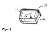
- FIG. 2 shows the adapter 116 in a perspective view substantially tubular shape with a substantially rectangular cross section.
- the connector 108 is immersed with its collar 118 in the adapter 116 and the locking slide 133 of the Mating connector 106 engages around the adapter 116.
- the locking lugs engage 132, which are arranged on the two opposite side walls, in the associated grooves 133 of the locking slide 126.
- Connection via the locking slide 126 are also other locking principles like a gear with a catch, a catch, a screw, one Welding, gluing or the like is conceivable.
- an elastic seal 134 is molded all around the adapter 116.
- seal 134 could also be manufactured as a separate part and then into a corresponding one Guide groove on the adapter 116 are inserted.
- the two locking arms 130 on the outside of the adapter 116 are so configured such that the adapter is inserted in the direction of plugging together 146 is easily possible, but the adapter is then firmly locked to the plate 104.
- the attachment of the adapter 116 on the middle plate 104 can also be screwed, riveted, Gluing, vibration welding or the like.
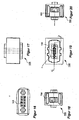
- FIGS. 9 to 14 show different views of a possible embodiment of the Seal 136 shown.
- the seal is preferably made of an elastic material z. B. made of a silicone material.
- FIG. 15 A perspective view of the mating connector 106 is shown in FIG. 15.
- the mating connector 106 openings 148 for Through (not shown here) has electrical cables.
- the mating connector 106 it is also used of the opening pointing upwards in FIG. 15 is pushed over the adapter 116. Subsequently becomes the locking slide in a direction transverse to the plugging direction 146 126 inserted.
- the mating connector is now mechanical firmly connected to the adapter 116. It is important that only the mechanical connection comes about via the adapter 116.
- the electrical contact is made immediately between the contact elements of the mating connector 106 and those of the connector 108. In this way the contact resistances can be particularly low maintained and the safety of the connector is increased, especially in the event of strong vibrations become.
- FIGS. 16 through 21 Different views of the mating connector 106 are shown in FIGS. 16 through 21 shown.
- the contact elements of the mating connector are in the embodiment shown 106 contact sockets, which are arranged in the openings 149. Of course but could also provide contact pins on the mating connector 106 his.
- the locking slide 126 is shown in perspective.
- the locking slide 126 has a substantially fork-like shape, whereby two symmetrically arranged arms, each with two grooves 133, are arranged in this way that they are simultaneously in the guide rails 150 on the mating connector can be introduced.
- An actuator 152 allows the actuation of the locking slide 126 by a technician.
- FIGS Different views of the locking slide 126 are shown in FIGS shown.
- the assembly 102 has a housing plate 154 on which the connector 108 is arranged is.
- the cover 122 which is shown in Figure 1, is on this housing plate 154, which contains the electronic circuits.
- the design of the collar 118 can be seen. It points the collar 118 has latching openings 144 for the latching projections 142 of the adapter 116.
- Guide grooves 140 facilitate the positioning of the connector pins of the mating connector 106 compared to the connector 108.
- the completely assembled connector arrangement 100 is without the sheet 104 is shown in different views. They are also not shown electrical leads as well as the electronic components and the cover 122.
Landscapes
- Connector Housings Or Holding Contact Members (AREA)
- Details Of Connecting Devices For Male And Female Coupling (AREA)
Abstract
Description
- Figur 1
- eine Explosionszeichnung der erfindungsgemäßen Steckverbinderanordnung;
- Figur 2
- eine perspektivische Darstellung des Adapters aus Figur 1;
- Figur 3
- eine Seitenansicht des Adapters;
- Figur 4
- eine weitere Seitenansicht des Adapters;
- Figur 5
- eine Draufsicht auf den Adapter;
- Figur 6
- ein Schnittbild des Adapters entlang der Schnittlinie B-B aus Figur 7;
- Figur 7
- ein Schnittbild des Adapters entlang der Schnittlinie A-A aus Figur 6;
- Figur 8
- ein Detail X aus Figur 7;
- Figur 9
- eine perspektivische Darstellung der Dichtung aus Figur 1;
- Figur 10
- eine Draufsicht auf die Dichtung aus Figur 9;
- Figur 11
- ein Schnittbild der Dichtung entlang der Schnittlinie B-B der Figur 10;
- Figur 12
- eine Seitenansicht der Dichtung aus Figur 9;
- Figur 13
- ein Detail X aus dem Schnittbild der Figur 11;
- Figur 14
- eine Ansicht von unten auf die Dichtung der Figur 9;
- Figur 15
- eine perspektivische Darstellung des Gegensteckverbinders aus Figur 1;
- Figur 16
- ein vergrößertes Detail Y der Ansicht aus Figur 19;
- Figur 17
- eine Seitenansicht des Gegensteckverbinders der Figur 15;
- Figur 18
- eine weitere Seitenansicht des Gegensteckverbinders der Figur 15;
- Figur 19
- eine Ansicht von oben auf den Steckverbinder der Figur 15;
- Figur 20
- eine weitere Seitenansicht des Steckverbinders der Figur 15;
- Figur 21
- ein Schnittbild des Gegensteckverbinders der Figur 15 entlang der Schnittlinie A-A aus Figur 19;
- Figur 22
- eine perspektivische Darstellung des Verriegelungsschiebers aus Figur 1;
- Figur 23
- eine Seitenansicht des Verriegelungsschiebers der Figur 22;
- Figur 24
- eine weitere Seitenansicht des Verriegelungsschiebers der Figur 22;
- Figur 25
- eine weitere Seitenansicht des Verriegelungsschiebers der Figur 22;
- Figur 26
- eine weitere Seitenansicht des Verriegelungsschiebers der Figur 22;
- Figur 27
- eine weitere Seitenansicht des Verriegelungsschiebers der Figur 22;
- Figur 28
- eine perspektivische Darstellung einer Gehäuseplatte der Baugruppe aus Figur 1, an der der Steckverbinder angeordnet ist;
- Figur 29
- eine Seitenansicht der Gehäuseplatte aus Figur 28;
- Figur 30
- ein Detail X der Ansicht der Gehäuseplatte aus Figur 33, in dem der Steckverbinder dargestellt ist;
- Figur 31
- eine Draufsicht auf die Gehäuseplatte der Figur 28;
- Figur 32
- eine weitere Seitenansicht der Gehäuseplatte der Figur 28;
- Figur 33
- eine Ansicht von unten der Gehäuseplatte aus Figur 28;
- Figur 34
- eine weitere Seitenansicht der Gehäuseplatte aus Figur 28;
- Figur 35
- einen Schnitt durch den Kragen entlang der Schnittlinie A-A der Figur 31;
- Figur 36
- eine Ansicht von unten auf die Gehäuseplatte der Figur 28 bei montiertem Gegenstecker;
- Figur 37
- eine Seitenansicht der Gehäuseplatte mit montiertem Gegenstecker;
- Figur 38
- eine weitere Seitenansicht der Gehäuseplatte aus Figur 36;
- Figur 39
- eine weitere Ansicht der Gehäuseplatte aus Figur 36;
- Figur 40
- eine Ansicht von oben auf die Gehäuseplatte mit montiertem Gegensteckverbinder;
- Figur 41
- ein Detail X aus Figur 36.
Claims (18)
- Elektrische Steckverbinderanordnung zum Verbinden eines an einer Baugruppe (102) angeordneten Steckverbinders (108) mit einem Gegensteckverbinder (106), wobei die Baugruppe (102) von dem Gegensteckverbinder (106) durch ein ortsfestes Karosserieteil (104) eines Kraftfahrzeugs, in dem eine entsprechende Aussparung für die Steckverbinderanordnung (100) vorgesehen ist, getrennt ist, und der Steckverbinder (108) mit dem Gegensteckverbinder (106) zusammensteckbar ist, um eine elektrische Verbindung herzustellen,
dadurch gekennzeichnet, dass die Steckverbinderanordnung (100) einen Adapter (116) aufweist, der so ausgebildet ist, dass er mit dem Steckverbinder (108), dem Gegensteckverbinder (106) und dem Karosserieteil (104) zusammenwirkt, um im gelösten Zustand der Steckverbinderanordnung (100) wenigstens ein Teil derselben an dem Karosserieteil (104) mechanisch zu fixieren. - Elektrische Steckverbinderanordnung nach Anspruch 1, dadurch gekennzeichnet, dass der Adapter (116) eine im Wesentlichen rohrförmige Gestalt aufweist.
- Elektrische Steckverbinderanordnung nach Anspruch 1 oder 2, dadurch gekennzeichnet, dass der Adapter (116) eine erste Haltevorrichtung (130) aufweist, die so ausgestaltet ist, dass der Adapter (116) in der Aussparung des ortsfesten Karosserieteils (104) gehalten ist.
- Elektrische Steckverbinderanordnung nach Anspruch 3, dadurch gekennzeichnet, dass die erste Haltevorrichtung mindestens ein Rastarm ist (130), der den Adapter (116) durch Verspreizen in der Aussparung hält.
- Elektrische Steckverbinderanordnung nach Anspruch 3, dadurch gekennzeichnet, dass die erste Haltevorrichtung durch eine Schraubverbindung, eine Nietverbindung, eine Klebeverbindung oder eine Schweißverbindung, vorzugsweise eine Vibrationsschweißverbindung, die den Adapter (116) in der Aussparung hält, gebildet ist.
- Elektrische Steckverbinderanordnung nach einem der Ansprüche 1 bis 7, dadurch gekennzeichnet, dass der Adapter eine zweite Haltevorrichtung (132) aufweist, die mit dem Gegensteckverbinder (106) so zusammenwirkt, dass der Gegensteckverbinder (106) sowohl im zusammengesteckten wie auch im gelösten Zustand der Steckverbinderanordnung (100) an dem Adapter (116) fixiert ist.
- Elektrische Steckverbinderanordnung nach Anspruch 6, dadurch gekennzeichnet, dass die zweite Haltevorrichtung aus wenigstens einer Verriegelungsnase (132) besteht und in dem Gegensteckverbinder (106) wenigstens eine entsprechende Nut (133) ausgebildet ist, in welche die Verriegelungsnase (132) eingreift.
- Elektrische Steckverbinderanordnung nach Anspruch 6 oder 7, dadurch gekennzeichnet, dass der Gegensteckverbinder (106) einen Verriegelungsschieber (126) aufweist und der Verriegelungsschieber (126) in mindestens einer Führungsschiene (150) des Gegensteckverbinders (106) gehalten ist.
- Elektrische Steckverbinderanordnung nach Anspruch 6 oder 7, dadurch gekennzeichnet, dass der Gegensteckverbinder (106) ein Getriebe mit einer Verrastung aufweist.
- Elektrische Steckverbinderanordnung nach Anspruch 6, dadurch gekennzeichnet, dass die zweite Haltevorrichtung aus wenigstens einer Rastvorrichtung besteht, die mit einer entsprechenden Gegenrastvorrichtung an dem Gegensteckverbinder (106) zusammenwirkt.
- Elektrische Steckverbinderanordnung nach Anspruch 6, dadurch gekennzeichnet, dass die zweite Haltevorrichtung (132) durch wenigstens eine Schraubverbindung, Nietverbindung, Klebeverbindung oder Schweißverbindung, vorzugsweise Vibrationsschweißverbindung gebildet ist.
- Elektrische Steckverbinderanordnung nach einem der Ansprüche 1 bis 11, dadurch gekennzeichnet, dass der Adapter (116) eine erste Dichtung (134) aufweist, welche die Verbindung zwischen dem Adapter (116) und dem ortsfesten Karosserieteil (104) abdichtet.
- Elektrische Steckverbinderanordnung nach einem der Ansprüche 1 bis 12, dadurch gekennzeichnet, dass der Gegensteckverbinder (106) eine zweite Dichtung (136) aufweist, welche die Verbindung zwischen dem Adapter (116) und dem Gegensteckverbinder (106) abdichtet.
- Elektrische Steckverbinderanordnung nach einem der Ansprüche 1 bis 13, dadurch gekennzeichnet, dass der Steckverbinder (108) an der Baugruppe (102) einen Kragen (118) aufweist, der im montierten Zustand der Baugruppe (102) an dem Karosserieteil (104) zumindest teilweise in den Adapter (116) eintaucht.
- Elektrische Steckverbinderanordnung nach Anspruch 14, dadurch gekennzeichnet, dass der Kragen (118) an seiner Außenseite mindestens eine Führungsnut (140) aufweist, in die ein zugehöriger Führungsvorsprung (138), der an der inneren Oberfläche des Adapters (116) angeformt ist, zum Führen des Steckverbinders (108) beim Zusammenstecken der Steckverbinderanordnung (100) eingreift.
- Elektrische Steckverbinderanordnung nach Anspruch 14 oder 15, dadurch gekennzeichnet, dass der Kragen (118) an seiner Außenseite mindestens eine Rastöffnung (144) aufweist, in die ein zugehöriger Rastvorsprung (142), der an der inneren Oberfläche des Adapters (116) angeformt ist, zum Fixieren des Steckverbinders (108) mit dem Adapter (116) einrastet.
- Verfahren zur Bildung einer elektrischen Steckverbindung zwischen einem an einer Baugruppe angeordneten Steckverbinder mit einem Gegensteckverbinder, wobei die Baugruppe von dem Gegensteckverbinder durch ein ortsfestes Karosserieteil, in dem eine entsprechende Aussparung für die Steckverbinderanordnung vorgesehen ist, getrennt ist, und der Steckverbinder mit dem Gegensteckverbinder zusammensteckbar ist, um eine elektrische Verbindung herzustellen, und wobei das Verfahren die folgenden Schritte aufweist:Aufstecken eines Adapters auf den Steckverbinder der Baugruppe,Befestigen der Baugruppe an dem Karosserieteil in einer Weise, dass der Steckverbinder für den Gegensteckverbinder zugänglich ist und der Adapter an dem Karosserieteil fixiert ist,Zusammenstecken des Gegensteckverbinders mit dem Steckverbinder, wobei die elektrische Verbindung zwischen dem Stecker und dem Gegensteckverbinder hergestellt wird und der Adapter so mit dem Steckverbinder und dem Gegensteckverbinder zusammenwirkt, dass im wieder gelösten Zustand der Steckverbinderanordnung wenigstens ein Teil derselben an dem Karosserieteil mechanisch fixiert bleibt.
- Verfahren nach Anspruch 17, dadurch gekennzeichnet, dass zum Fixieren des Gegensteckverbinders an dem Adapter ein Verriegelungsschieber so in einer Richtung quer zur Richtung des Zusammensteckens in einer Führungsschiene des Gegensteckers verschoben wird, dass eine Verriegelungsnase, die an dem Adapter angeformt ist, in einer Verriegelungsnut an dem Verriegelungsschieber eingreift.
Priority Applications (1)
| Application Number | Priority Date | Filing Date | Title |
|---|---|---|---|
| EP20030007442 EP1355387B1 (de) | 2002-04-17 | 2003-04-03 | Elektrischer Steckverbinderanordnung an einem ortsfesten Karosserieteil eines Kraftfahrzeugs und Verfahren zur Bildung einer solchen elektrischen Steckverbindung |
Applications Claiming Priority (3)
| Application Number | Priority Date | Filing Date | Title |
|---|---|---|---|
| EP02008646 | 2002-04-17 | ||
| EP02008646 | 2002-04-17 | ||
| EP20030007442 EP1355387B1 (de) | 2002-04-17 | 2003-04-03 | Elektrischer Steckverbinderanordnung an einem ortsfesten Karosserieteil eines Kraftfahrzeugs und Verfahren zur Bildung einer solchen elektrischen Steckverbindung |
Publications (2)
| Publication Number | Publication Date |
|---|---|
| EP1355387A1 true EP1355387A1 (de) | 2003-10-22 |
| EP1355387B1 EP1355387B1 (de) | 2010-12-15 |
Family
ID=28676386
Family Applications (1)
| Application Number | Title | Priority Date | Filing Date |
|---|---|---|---|
| EP20030007442 Expired - Lifetime EP1355387B1 (de) | 2002-04-17 | 2003-04-03 | Elektrischer Steckverbinderanordnung an einem ortsfesten Karosserieteil eines Kraftfahrzeugs und Verfahren zur Bildung einer solchen elektrischen Steckverbindung |
Country Status (1)
| Country | Link |
|---|---|
| EP (1) | EP1355387B1 (de) |
Citations (5)
| Publication number | Priority date | Publication date | Assignee | Title |
|---|---|---|---|---|
| EP0192254A2 (de) * | 1985-02-20 | 1986-08-27 | Contact GmbH Elektrische Bauelemente | Vielpoliger, steckbarer Klemmenadapter für Schalt- oder Steuerschränke |
| WO1989011171A1 (en) * | 1988-05-06 | 1989-11-16 | United Technologies Automotive, Inc. | Vehicular modular door panel assembly with laterally extended electrical contact interfacing |
| DE4040748A1 (de) * | 1989-12-20 | 1991-07-04 | Yazaki Corp | Verbindungsvorrichtung |
| EP0801442A1 (de) * | 1996-04-09 | 1997-10-15 | Harness System Technologies Research, Ltd. | Verbindungsvorrichtung für elektrische Steckverbinder |
| EP0896397A2 (de) * | 1997-08-08 | 1999-02-10 | Yazaki Corporation | Verbindungsanordnung eines Verbinders |
-
2003
- 2003-04-03 EP EP20030007442 patent/EP1355387B1/de not_active Expired - Lifetime
Patent Citations (5)
| Publication number | Priority date | Publication date | Assignee | Title |
|---|---|---|---|---|
| EP0192254A2 (de) * | 1985-02-20 | 1986-08-27 | Contact GmbH Elektrische Bauelemente | Vielpoliger, steckbarer Klemmenadapter für Schalt- oder Steuerschränke |
| WO1989011171A1 (en) * | 1988-05-06 | 1989-11-16 | United Technologies Automotive, Inc. | Vehicular modular door panel assembly with laterally extended electrical contact interfacing |
| DE4040748A1 (de) * | 1989-12-20 | 1991-07-04 | Yazaki Corp | Verbindungsvorrichtung |
| EP0801442A1 (de) * | 1996-04-09 | 1997-10-15 | Harness System Technologies Research, Ltd. | Verbindungsvorrichtung für elektrische Steckverbinder |
| EP0896397A2 (de) * | 1997-08-08 | 1999-02-10 | Yazaki Corporation | Verbindungsanordnung eines Verbinders |
Also Published As
| Publication number | Publication date |
|---|---|
| EP1355387B1 (de) | 2010-12-15 |
Similar Documents
| Publication | Publication Date | Title |
|---|---|---|
| EP1511368B1 (de) | Sandwich Gehäuse für einen Antennenverstärker | |
| EP3613106B1 (de) | Halterahmen für einen steckverbinder und verfahren zur bestückung | |
| EP2780200B1 (de) | Gehäuse und bausatz für eine steuerungsvorrichtung | |
| WO2009062709A1 (de) | Türantrieb | |
| DE102008051545B4 (de) | Elektronisches Gerät mit Mehrkontaktstecker und Verfahren zur Herstellung desselben | |
| DE102007009644A1 (de) | Elektronische Baugruppe mit Steckverbindung | |
| EP0982978B1 (de) | Gehäuse, insbesondere Schlossgehäuse mit elektrischen Anschlusseinrichtungen | |
| DE20113304U1 (de) | Fahrzeuginnenraummodul | |
| WO2007090741A1 (de) | Elektronische steuerungseinheit, insbesondere zur steuerung eines sicherheitssystems und/oder komfortsystems in einem kraftfahrzeug | |
| DE102012102842A1 (de) | Befestigung und Abdichtung von Steckanschlussmodulen in einer Gehäusewand | |
| DE102020210278A1 (de) | Haushaltsgerät mit einer Kamera und einem damit verbundenen Hinterlegteil, sowie Verfahren | |
| DE10018931C2 (de) | Schaltkreisverbindungsanordnung für einen Kabelstrang in einem Fahrzeug | |
| EP2609799B1 (de) | Verschlusssystem für baugruppen am gehäuse und montageverfahren | |
| DE4435287C1 (de) | Verbindungsvorrichtung | |
| EP1355387B1 (de) | Elektrischer Steckverbinderanordnung an einem ortsfesten Karosserieteil eines Kraftfahrzeugs und Verfahren zur Bildung einer solchen elektrischen Steckverbindung | |
| DE102011080811A1 (de) | Elektrische Vorrichtung mit einem EMV-dichten Gehäuse | |
| DE102005036910A1 (de) | Vorrichtung zum Aneinanderfügen des Gehäuses von Funktionsteilen und einer Blende | |
| DE19911989C2 (de) | Metallgehäuse | |
| DE19846196A1 (de) | Verbinder für eine Fahrzeug-Batterie | |
| DE10208106A1 (de) | Baugruppe zur Montage eines Türsteuermoduls für ein Kraftfahrzeug | |
| EP2301123B1 (de) | Bedienelement mit installationseinheit | |
| EP1185998A1 (de) | Vorrichtung zur lagerichtigen befestigung einer leiterplatte | |
| DE102007030213B4 (de) | Lenksäulenmodul für ein Kraftfahrzeug | |
| EP1035617A1 (de) | Verbindungselement | |
| DE102023125287A1 (de) | Steckverbindungseinrichtung und elektrische Antriebseinheit |
Legal Events
| Date | Code | Title | Description |
|---|---|---|---|
| PUAI | Public reference made under article 153(3) epc to a published international application that has entered the european phase |
Free format text: ORIGINAL CODE: 0009012 |
|
| AK | Designated contracting states |
Kind code of ref document: A1 Designated state(s): AT BE BG CH CY CZ DE DK EE ES FI FR GB GR HU IE IT LI LU MC NL PT RO SE SI SK TR |
|
| AX | Request for extension of the european patent |
Extension state: AL LT LV MK |
|
| 17P | Request for examination filed |
Effective date: 20031117 |
|
| AKX | Designation fees paid |
Designated state(s): DE FR GB |
|
| RBV | Designated contracting states (corrected) |
Designated state(s): DE FR GB IT |
|
| 17Q | First examination report despatched |
Effective date: 20080619 |
|
| GRAP | Despatch of communication of intention to grant a patent |
Free format text: ORIGINAL CODE: EPIDOSNIGR1 |
|
| GRAS | Grant fee paid |
Free format text: ORIGINAL CODE: EPIDOSNIGR3 |
|
| GRAA | (expected) grant |
Free format text: ORIGINAL CODE: 0009210 |
|
| AK | Designated contracting states |
Kind code of ref document: B1 Designated state(s): DE FR GB IT |
|
| REG | Reference to a national code |
Ref country code: GB Ref legal event code: FG4D Free format text: NOT ENGLISH |
|
| REF | Corresponds to: |
Ref document number: 50313315 Country of ref document: DE Date of ref document: 20110127 Kind code of ref document: P |
|
| PLBE | No opposition filed within time limit |
Free format text: ORIGINAL CODE: 0009261 |
|
| STAA | Information on the status of an ep patent application or granted ep patent |
Free format text: STATUS: NO OPPOSITION FILED WITHIN TIME LIMIT |
|
| 26N | No opposition filed |
Effective date: 20110916 |
|
| REG | Reference to a national code |
Ref country code: DE Ref legal event code: R097 Ref document number: 50313315 Country of ref document: DE Effective date: 20110916 |
|
| REG | Reference to a national code |
Ref country code: FR Ref legal event code: PLFP Year of fee payment: 13 |
|
| REG | Reference to a national code |
Ref country code: DE Ref legal event code: R082 Ref document number: 50313315 Country of ref document: DE Representative=s name: GRUENECKER PATENT- UND RECHTSANWAELTE PARTG MB, DE Ref country code: DE Ref legal event code: R081 Ref document number: 50313315 Country of ref document: DE Owner name: TE CONNECTIVITY GERMANY GMBH, DE Free format text: FORMER OWNER: TYCO ELECTRONICS AMP GMBH, 64625 BENSHEIM, DE |
|
| PGFP | Annual fee paid to national office [announced via postgrant information from national office to epo] |
Ref country code: DE Payment date: 20150429 Year of fee payment: 13 Ref country code: GB Payment date: 20150427 Year of fee payment: 13 |
|
| PGFP | Annual fee paid to national office [announced via postgrant information from national office to epo] |
Ref country code: IT Payment date: 20150424 Year of fee payment: 13 Ref country code: FR Payment date: 20150417 Year of fee payment: 13 |
|
| REG | Reference to a national code |
Ref country code: FR Ref legal event code: CD Owner name: TE CONNECTIVITY GERMANY GMBH Effective date: 20151027 |
|
| REG | Reference to a national code |
Ref country code: DE Ref legal event code: R119 Ref document number: 50313315 Country of ref document: DE |
|
| GBPC | Gb: european patent ceased through non-payment of renewal fee |
Effective date: 20160403 |
|
| REG | Reference to a national code |
Ref country code: FR Ref legal event code: ST Effective date: 20161230 |
|
| PG25 | Lapsed in a contracting state [announced via postgrant information from national office to epo] |
Ref country code: FR Free format text: LAPSE BECAUSE OF NON-PAYMENT OF DUE FEES Effective date: 20160502 Ref country code: GB Free format text: LAPSE BECAUSE OF NON-PAYMENT OF DUE FEES Effective date: 20160403 Ref country code: DE Free format text: LAPSE BECAUSE OF NON-PAYMENT OF DUE FEES Effective date: 20161101 |
|
| PG25 | Lapsed in a contracting state [announced via postgrant information from national office to epo] |
Ref country code: IT Free format text: LAPSE BECAUSE OF NON-PAYMENT OF DUE FEES Effective date: 20160403 |