EP1355333A2 - Tastatur, vorzugsweise für Datenkassen - Google Patents
Tastatur, vorzugsweise für Datenkassen Download PDFInfo
- Publication number
- EP1355333A2 EP1355333A2 EP03007575A EP03007575A EP1355333A2 EP 1355333 A2 EP1355333 A2 EP 1355333A2 EP 03007575 A EP03007575 A EP 03007575A EP 03007575 A EP03007575 A EP 03007575A EP 1355333 A2 EP1355333 A2 EP 1355333A2
- Authority
- EP
- European Patent Office
- Prior art keywords
- housing shell
- housing
- keyboard according
- keyboard
- shell
- Prior art date
- Legal status (The legal status is an assumption and is not a legal conclusion. Google has not performed a legal analysis and makes no representation as to the accuracy of the status listed.)
- Granted
Links
Images

Classifications
-
- H—ELECTRICITY
- H01—ELECTRIC ELEMENTS
- H01H—ELECTRIC SWITCHES; RELAYS; SELECTORS; EMERGENCY PROTECTIVE DEVICES
- H01H13/00—Switches having rectilinearly-movable operating part or parts adapted for pushing or pulling in one direction only, e.g. push-button switch
- H01H13/70—Switches having rectilinearly-movable operating part or parts adapted for pushing or pulling in one direction only, e.g. push-button switch having a plurality of operating members associated with different sets of contacts, e.g. keyboard
-
- H—ELECTRICITY
- H01—ELECTRIC ELEMENTS
- H01H—ELECTRIC SWITCHES; RELAYS; SELECTORS; EMERGENCY PROTECTIVE DEVICES
- H01H2223/00—Casings
- H01H2223/002—Casings sealed
- H01H2223/004—Evacuation of penetrating liquid
-
- H—ELECTRICITY
- H01—ELECTRIC ELEMENTS
- H01H—ELECTRIC SWITCHES; RELAYS; SELECTORS; EMERGENCY PROTECTIVE DEVICES
- H01H2223/00—Casings
- H01H2223/01—Mounting on appliance
- H01H2223/014—Mounting on appliance located in recess
-
- H—ELECTRICITY
- H01—ELECTRIC ELEMENTS
- H01H—ELECTRIC SWITCHES; RELAYS; SELECTORS; EMERGENCY PROTECTIVE DEVICES
- H01H2231/00—Applications
- H01H2231/006—Bank automat; Cash register; Vending machine
Definitions
- the invention relates to a keyboard according to the preamble of claim 1.
- EP 1 172 832 A2 describes a generic keyboard for a data register with a one-piece keyboard housing known.
- the housing has an upper and a lower one Housing shell, which connect to each other essentially S-shaped.
- a keypad is slanted through the housing shell.
- Below the keypad keyboard electronics is arranged, for example.
- the bottom side or surface the upper housing shell is made flat in relation to an imaginary contact surface. From the depressions of the lower housing shell adjoining this surface electrical connections of additional modules protrude into the upper housing shell.
- the object of the invention is to show a further simple keyboard, which is easy to assemble, service and cost-effective.
- the invention is based on the idea of creating a one-piece housing, consisting of an upper and a lower open housing shell, the upper open housing shell being designed in cooperation with a keypad in such a way that it is trough-like and is preferably arranged obliquely within the housing.
- the lower side or base of the upper open housing shell is part of the lower open housing shell.
- the lower open housing shell has an area for the installation of a card reader and can be recognized as an elevation or as a flat housing end within the upper side of the housing. This area joins the common area, for example as a depression. Further depressions which are provided in the lower open housing shell can also be recognized as the housing end of the upper housing shell.
- the preferred inclined position of the upper housing shell ensures, among other things, that moisture that enters can run off through slots that can be introduced into the housing.
- the keypad is firmly connected to the lower housing shell, but can also be detachably connected to it.
- the lower housing shell has in the area of the common Surface a stiffener.
- a stiffener As a result, high stability can be achieved, what can be done for example by a thicker surface.
- this stiffening is realized by longitudinal and / or transverse webs that preferably replicate an H shape.
- H - shape the possibility of electronic assemblies, such as keyboard electronics, to integrate into this.
- Other accommodation locations are also those already described Recesses in the lower housing shell.
- the keypad can be due to the complex support within the tub of the upper case dispense with an otherwise necessary carrier plate and is also cost-optimized.
- the housing itself is a molded plastic part. This is due to the design of the housing also simple and inexpensive to manufacture.
- the new design of the keyboard housing and the keypad save material as well as weight savings possible without sacrificing the stiffness and quality to reduce.
- the ease of service and installation is increased because, for example, the keypad does not have to be solved if the keyboard electronics are changed, for example shall be.
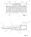
- Fig. 1 shows a keyboard 10, for example a terminal for a POS terminal, in one Top view.
- the keyboard 10 has a keyboard housing 1 with a keypad 11, which is held in the housing 1.
- this keyboard 10 also has a card reader 12. This can be a magnetic and / or a chip card reader.
- the keyboard housing 1 is preferably made of plastic and is made of one piece Basic body formed by an upper open housing shell 2 and a lower open Housing shell 3 is described, as shown in section in Fig. 2.
- the upper open housing shell 2 is designed like a tub and inserted or attached obliquely within the housing 1. Within the tub, there are preferably: no further details belonging to the housing shell 2, so that the keypad 11 can rest flat or only partially on a lower surface 4 of the tub.
- the lower surface 4 of the tub is on the rear part of the lower open housing shell 3, as a result of which the upper open housing shell 2 and the lower open housing shell 3 complement each other to form an approximately 1-shaped housing (1) in cross section.
- the lower open housing shell 3 has stiffening webs 5 below the lower surface 4 of the upper housing shell 2.
- the lower open housing shell 3 has following this common surface 4 and the stiffeners 5, for example parallel to an imaginary support surface in this embodiment, two smaller recesses 6 and a larger central recess 7, which in particular for receiving electronic modules, such as additional modules or plug connections can serve.
- the two housing shells 2 and 3 additionally reproduce in cross section a angeh shape attached to the ⁇ shape.
- the central recesses 6 are preferably provided for receiving electronics 8 of the magnetic card and / or chip card reader 12.
- the recess 7, like the recesses 6, can end with the housing border of the upper housing shell 2 formed by the trough.
- Fig. 3 the keyboard housing 1 is shown in a perspective view in a plan view.
- the breakthroughs 2.1 visible here from the upper open housing shell 2 into the lower open housing shell 3 allow the guide frame of the keypad 11 to be screwed to the lower open housing shell 3, caulked or fastened in some other way.
- the keypad 11 is designed so that it preferably fills the entire tub space.
- the flat or partial support in the basic body of the housing means that an otherwise necessary carrier plate can be dispensed with.
- Fig. 4 shows the bottom view of the keyboard housing 1.
- Form the webs 5 for stiffening preferably one or two H forms. This form creates free spaces 9, in the further electronic not shown here or the modules already mentioned can be introduced. It is advantageous to integrate the keyboard electronics (not closer shown) in the lower housing shell 3, in particular in one of the free spaces 9. Die electrical connection of the individual electronic assemblies, such as with the keyboard electronics, with the corresponding counterparts, such as the Keypad 11 is ensured.
- the open lower housing shell 3 is provided with a cover 13 to prevent it from falling out to avoid the electronic assemblies.
- the card reader 12 can also be integrated on the side next to the keypad 11.
- the cover 13 can consist of a plastic.
- the stiffening can also be achieved by a slight thickening or by a thicker cross section of the common surface 4.
- the surface 4 can also run flat in the keyboard housing 1, in which case no free spaces are preferably formed below this surface.
- the entire electronics can then be accommodated in the recesses 6, 7.
Landscapes
- Input From Keyboards Or The Like (AREA)
- Cash Registers Or Receiving Machines (AREA)
- Casings For Electric Apparatus (AREA)
Abstract
Description
Die untere offene Gehäuseschale weist einen Bereich für den Einbau eines Kartenleser auf und kann innerhalb der oberen Seite des Gehäuses als Erhebung oder als planer Gehäuseabschluß erkannt werden. Dieser Bereich schließt sich der gemeinsamen Fläche beispielsweise als Vertiefung an.
Weitere Vertiefungen, die in der unteren offenen Gehäuseschale vorgesehen sind, können ebenfalls als Gehäuseabschluß der oberen Gehäuseschale erkannt werden.
Das Tastenfeld wird mit der unteren Gehäuseschale fest verbunden, kann aber auch lösbar mit dieser verbunden sein.
- Fig. 1
- eine vereinfacht dargestellte Tastatur in einer Draufsicht,
- Fig. 2
- eine Schnittdarstellung des Tastaturgehäuses im Schnitt I-I aus Fig. 1 ohne Tastenfeld,
- Fig. 3
- eine perspektivische Draufsichtdarstellung auf das Tastaturgehäuse,
- Fig.4
- eine perspektivische Ansicht der Unterseite des Tastaturgehäuses.
Die untere Fläche 4 der Wanne ist rückseitig Teil der unteren offenen Gehäuseschale 3, wodurch die obere offene Gehäuseschale 2 und die untere offene Gehäuseschale 3 sich zu einem im Querschnitt etwa Λ- förmigen Gehäuse (1) ergänzen.
Zur besseren Stabilität weist die untere offene Gehäuseschale 3 unterhalb der unteren Fläche 4 der oberen Gehäuseschale 2 Versteifungsstege 5 auf.
Die mittigen Vertiefungen 6 ist vorzugsweise zur Aufnahme einer Elektronik 8 des Magnetkarten- und /oder Chipkartenlesers 12 vorgesehen. Die Vertiefung 7 kann wie die Vertiefungen 6 mit der durch die Wanne gebildeten Gehäuseumrandung der oberen Gehäuseschale 2 abschließen.
Das Tastenfeld 11 ist so konzipiert, dass dieses vorzugsweise den gesamten Wannenraum ausfüllt. Durch das plane oder auch partielle Aufliegen im Gehäusegrundkörper kann auf eine sonst notwendige Trägerplatte verzichtet werden.
So kann der Kartenleser 12 auch seitlich, neben dem Tastenfeld 11 eingebunden sein. Zudem kann die Abdeckung 13 aus einem Kunststoff bestehen.
Die Versteifung ist auch durch eine leichte Verdickung oder durch einen dickeren Querschnitt der gemeinsamen Fläche 4 realisierbar.
Die Fläche 4 kann auch flach im Tastaturgehäuse 1 verlaufen, wobei dann unterhalb dieser Fläche vorzugsweise keine Freiräume gebildet werden. Die gesamte Elektronik kann dann in den Vertiefungen 6, 7 untergebracht werden.
Claims (11)
- Tastatur, vorzugsweise für Datenkassen, mit einem Gehäuse zur Aufnahme zumindesteines Tastenfeldes,wobei das Gehäuse einteilig ausgeführt ist, welchesaus einer offenen oberen Gehäuseschale und einer unteren offenen Gehäuseschale gebildet wird, dadurch gekennzeichnet, dassdie obere offene Gehäuseschale (2) wannenartig ausgeführt ist, deren Grundfläche (4) Teil der unteren Gehäuseschale (3) ist,diese Fläche (4) innerhalb des Gehäuses (1) schräg verläuft, wodurchdie obere offene Gehäuseschale (2) und die untere offene Gehäuseschale sich zu einem im Querschnitt im wesentlichen darstellenden A-förmigen Gehäuse (1) ergänzen, wobeidie beiden offenen Gehäuseschalen (2, 3) im Querschnitt zusätzlich eine der Λ-Form angehängte Π-Form nachbilden können.
- Tastatur nach Anspruch 1, dadurch gekennzeichnet, dass an der Fläche (4) Versteifungen vorgesehen sind.
- Tastatur nach Anspruch 2, dadurch gekennzeichnet, dass die Versteifung durch Stege (5) realisiert wird.
- Tastatur nach Anspruch 3, dadurch gekennzeichnet, dass die Versteifung durch eine Verdickung der Fläche (4) realisiert wird.
- Tastatur nach Anspruch 3, dadurch gekennzeichnet, dass die Stege (5) eine H - Form nachbilden.
- Tastatur nach einem der Ansprüche 1 bis 5, dadurch gekennzeichnet, dass das Tastenfeld (11) an der unteren Gehäuseschale (3) befestigt wird, wozu die gemeinsame Fläche (4) Durchbrüche (2.1) aufweist.
- Tastatur nach einem der Ansprüche 1 bis 6, dadurch gekennzeichnet, dass das Tastenfeld (11) plan oder partiell in der Wanne der oberen Gehäuseschale (2) und dabei auf der gemeinsamen Fläche (4) aufliegt.
- Tastatur nach einen der Ansprüche, dadurch gekennzeichnet, dass in der unteren Gehäuseschale (3) im Anschluß an die gemeinsame Fläche (4) die Aufnahme eines Kartenlesers (12) vorgesehen ist, wozu die untere Gehäuseschale (3) eine sich der Fläche (4) anschließende Vertiefung (7) aufweist, die in der oberen Gehäuseschale (2) als Erhebung oder als planer Gehäuseabschluss erkannt wird.
- Tastatur nach einem der Ansprüche, dadurch gekennzeichnet, dass weitere Vertiefungen (6) der unteren Gehäuseschale (3) zur Aufnahme von elektronischen Baugruppen vorgesehen ist, welche als Gehäuseabschluß der oberen Gehäuseschale (2) erkannt werden.
- Tastatur nach einem der Ansprüche, dadurch gekennzeichnet, dass die elektronischen Baugruppen unterhalb der gemeinsamen Fläche (4) in der unteren Gehäuseschale (3) angebracht sind.
- Tastatur nach Anspruch 1, dadurch gekennzeichnet, dass das Tastenfeld (11) auf eine Trägerplatte verzichten kann.
Applications Claiming Priority (2)
| Application Number | Priority Date | Filing Date | Title |
|---|---|---|---|
| DE2002116936 DE10216936B4 (de) | 2002-04-17 | 2002-04-17 | Tastatur, vorzugsweise für Datenkassen |
| DE10216936 | 2002-04-17 |
Publications (3)
| Publication Number | Publication Date |
|---|---|
| EP1355333A2 true EP1355333A2 (de) | 2003-10-22 |
| EP1355333A3 EP1355333A3 (de) | 2006-08-16 |
| EP1355333B1 EP1355333B1 (de) | 2010-08-18 |
Family
ID=28458874
Family Applications (1)
| Application Number | Title | Priority Date | Filing Date |
|---|---|---|---|
| EP20030007575 Expired - Lifetime EP1355333B1 (de) | 2002-04-17 | 2003-04-02 | Tastatur, vorzugsweise für Datenkassen |
Country Status (3)
| Country | Link |
|---|---|
| EP (1) | EP1355333B1 (de) |
| CN (1) | CN1267944C (de) |
| DE (2) | DE10216936B4 (de) |
Families Citing this family (2)
| Publication number | Priority date | Publication date | Assignee | Title |
|---|---|---|---|---|
| DE102007042856A1 (de) | 2007-09-10 | 2009-03-12 | Preh Keytec Gmbh | Versenkbares Kartenmodul für eine Kassentastatur |
| DE102009054507A1 (de) | 2009-12-10 | 2011-06-16 | Zf Friedrichshafen Ag | Karten-Terminal |
Family Cites Families (6)
| Publication number | Priority date | Publication date | Assignee | Title |
|---|---|---|---|---|
| EP0263652B1 (de) * | 1986-10-06 | 1993-03-10 | Brother Kogyo Kabushiki Kaisha | Dateneingabevorrichtung |
| EP0305931A3 (de) * | 1987-08-31 | 1990-08-29 | Siemens Nixdorf Informationssysteme Aktiengesellschaft | Tastaturvorrichtung |
| DE29510328U1 (de) * | 1995-06-26 | 1995-09-28 | Silitek Corp | Computertastatur |
| US5865546A (en) * | 1997-08-29 | 1999-02-02 | Compaq Computer Corporation | Modular keyboard for use in a computer system |
| DE19811728C1 (de) * | 1998-03-18 | 1999-11-18 | Rose Elektrotech Gmbh | Tastaturgehäuse mit mindestens einem Tastaturfeld |
| DE10034346C2 (de) * | 2000-07-14 | 2002-05-23 | Preh Elektro Feinmechanik | Tastatur, vorzugsweise für Datenkassen |
-
2002
- 2002-04-17 DE DE2002116936 patent/DE10216936B4/de not_active Expired - Lifetime
-
2003
- 2003-04-02 DE DE50312988T patent/DE50312988D1/de not_active Expired - Lifetime
- 2003-04-02 EP EP20030007575 patent/EP1355333B1/de not_active Expired - Lifetime
- 2003-04-16 CN CN 03122621 patent/CN1267944C/zh not_active Expired - Fee Related
Also Published As
| Publication number | Publication date |
|---|---|
| DE10216936A1 (de) | 2003-11-27 |
| DE50312988D1 (de) | 2010-09-30 |
| CN1267944C (zh) | 2006-08-02 |
| EP1355333A3 (de) | 2006-08-16 |
| DE10216936B4 (de) | 2004-03-11 |
| EP1355333B1 (de) | 2010-08-18 |
| CN1452195A (zh) | 2003-10-29 |
Similar Documents
| Publication | Publication Date | Title |
|---|---|---|
| EP0335160B1 (de) | Steckverbinder mit abgewinkelten Kontaktpfosten zum Einpressen in Leiterplattenbohrungen | |
| DE69617823T2 (de) | Anordnung zur Verbindung einer Chipkarte mit Kontakten in einer Lese- und Schreibvorrichtung und zugehörige Kappe | |
| CH652348A5 (de) | Tastenwerk fuer tastaturen von elektrischen schreib- und aehnlichen maschinen. | |
| DE2839871A1 (de) | Schalttafelanordnung | |
| EP0338259A2 (de) | Modul für eine aus mehreren auf einem Träger nebeneinander angeordneten Modulen bestehenden Steuerung | |
| DE602006000112T2 (de) | Modularer allgemein einsetzbarer stapelbarer rechteckiger Verbinder | |
| EP1172832B1 (de) | Tastatur, vorzugsweise für Datenkassen | |
| DE60002996T2 (de) | Verbinder zur montage auf leiterplatten | |
| DE69626945T2 (de) | Aktiver Steckverbinder für Chipkarte | |
| EP1355333A2 (de) | Tastatur, vorzugsweise für Datenkassen | |
| DE19708221B4 (de) | Chipkartenleser mit einem Kartenanwesenheitsschalter | |
| EP0221201A1 (de) | Einbaugehäuse für elektrische und elektronische Schaltungen | |
| DE8808164U1 (de) | Einen Rechner mit einem Puzzlespiel kombinierende Vorrichtung | |
| DE69427128T2 (de) | Ic-karte mit trägereinstellungsmitteln | |
| EP0292607B1 (de) | Elektrisches Gerät, insbesondere elektrischer Schalter für Kraftfahrzeuge | |
| DE8419138U1 (de) | Funktionsblock zur Halterung mindestens einer Schaltungskarte auf einem Träger | |
| DE3737907A1 (de) | Elektrischer schalter, insbesondere lenkstockschalter fuer kraftfahrzeuge | |
| DE3874971T2 (de) | Anschlussmodul fuer elektrische leiter mit eingebauten bauteilen. | |
| DE10218442B3 (de) | Tastatur, insbesondere für Datenkassen | |
| DE69710562T2 (de) | PC-Karte | |
| DE20216755U1 (de) | Lenkrad | |
| DE60301460T2 (de) | Anordnung für die elektrische Verbindung eines Bauteils auf der Oberfläche einer Leiterplatte | |
| DE8432252U1 (de) | Gehäuse zur Aufnahme von Anzeige- oder Bedienelementen | |
| EP0554555B1 (de) | Mehrteiliges Schreibtischset | |
| DE60303080T2 (de) | Steckverbinder mit kurzer Abstandsanordnung der Kontakte |
Legal Events
| Date | Code | Title | Description |
|---|---|---|---|
| PUAI | Public reference made under article 153(3) epc to a published international application that has entered the european phase |
Free format text: ORIGINAL CODE: 0009012 |
|
| AK | Designated contracting states |
Kind code of ref document: A2 Designated state(s): AT BE BG CH CY CZ DE DK EE ES FI FR GB GR HU IE IT LI LU MC NL PT RO SE SI SK TR |
|
| AX | Request for extension of the european patent |
Extension state: AL LT LV MK |
|
| RIN1 | Information on inventor provided before grant (corrected) |
Inventor name: HOCHGESANG, GERHARD Inventor name: MALINOWSKI, ANDRZEJ Inventor name: SCHMOEGER, KLAUS |
|
| RAP1 | Party data changed (applicant data changed or rights of an application transferred) |
Owner name: PREH GMBH |
|
| RAP1 | Party data changed (applicant data changed or rights of an application transferred) |
Owner name: PREH KEYTEC GMBH |
|
| PUAL | Search report despatched |
Free format text: ORIGINAL CODE: 0009013 |
|
| AK | Designated contracting states |
Kind code of ref document: A3 Designated state(s): AT BE BG CH CY CZ DE DK EE ES FI FR GB GR HU IE IT LI LU MC NL PT RO SE SI SK TR |
|
| AX | Request for extension of the european patent |
Extension state: AL LT LV MK |
|
| 17P | Request for examination filed |
Effective date: 20070209 |
|
| AKX | Designation fees paid |
Designated state(s): DE FR GB |
|
| GRAP | Despatch of communication of intention to grant a patent |
Free format text: ORIGINAL CODE: EPIDOSNIGR1 |
|
| GRAS | Grant fee paid |
Free format text: ORIGINAL CODE: EPIDOSNIGR3 |
|
| GRAA | (expected) grant |
Free format text: ORIGINAL CODE: 0009210 |
|
| AK | Designated contracting states |
Kind code of ref document: B1 Designated state(s): DE FR GB |
|
| REG | Reference to a national code |
Ref country code: GB Ref legal event code: FG4D Free format text: NOT ENGLISH |
|
| REF | Corresponds to: |
Ref document number: 50312988 Country of ref document: DE Date of ref document: 20100930 Kind code of ref document: P |
|
| PLBI | Opposition filed |
Free format text: ORIGINAL CODE: 0009260 |
|
| PLAX | Notice of opposition and request to file observation + time limit sent |
Free format text: ORIGINAL CODE: EPIDOSNOBS2 |
|
| 26 | Opposition filed |
Opponent name: DESKO GMBH Effective date: 20110516 |
|
| PLBP | Opposition withdrawn |
Free format text: ORIGINAL CODE: 0009264 |
|
| REG | Reference to a national code |
Ref country code: DE Ref legal event code: R026 Ref document number: 50312988 Country of ref document: DE Effective date: 20110516 |
|
| PLAF | Information modified related to communication of a notice of opposition and request to file observations + time limit |
Free format text: ORIGINAL CODE: EPIDOSCOBS2 |
|
| PLBB | Reply of patent proprietor to notice(s) of opposition received |
Free format text: ORIGINAL CODE: EPIDOSNOBS3 |
|
| PLBD | Termination of opposition procedure: decision despatched |
Free format text: ORIGINAL CODE: EPIDOSNOPC1 |
|
| REG | Reference to a national code |
Ref country code: DE Ref legal event code: R084 Ref document number: 50312988 Country of ref document: DE Effective date: 20111222 |
|
| PLBM | Termination of opposition procedure: date of legal effect published |
Free format text: ORIGINAL CODE: 0009276 |
|
| STAA | Information on the status of an ep patent application or granted ep patent |
Free format text: STATUS: OPPOSITION PROCEDURE CLOSED |
|
| 27C | Opposition proceedings terminated |
Effective date: 20120210 |
|
| REG | Reference to a national code |
Ref country code: FR Ref legal event code: PLFP Year of fee payment: 14 |
|
| PGFP | Annual fee paid to national office [announced via postgrant information from national office to epo] |
Ref country code: GB Payment date: 20160421 Year of fee payment: 14 |
|
| PGFP | Annual fee paid to national office [announced via postgrant information from national office to epo] |
Ref country code: FR Payment date: 20160421 Year of fee payment: 14 |
|
| GBPC | Gb: european patent ceased through non-payment of renewal fee |
Effective date: 20170402 |
|
| REG | Reference to a national code |
Ref country code: FR Ref legal event code: ST Effective date: 20171229 |
|
| PG25 | Lapsed in a contracting state [announced via postgrant information from national office to epo] |
Ref country code: FR Free format text: LAPSE BECAUSE OF NON-PAYMENT OF DUE FEES Effective date: 20170502 |
|
| PG25 | Lapsed in a contracting state [announced via postgrant information from national office to epo] |
Ref country code: GB Free format text: LAPSE BECAUSE OF NON-PAYMENT OF DUE FEES Effective date: 20170402 |
|
| PGFP | Annual fee paid to national office [announced via postgrant information from national office to epo] |
Ref country code: DE Payment date: 20220420 Year of fee payment: 20 |
|
| REG | Reference to a national code |
Ref country code: DE Ref legal event code: R071 Ref document number: 50312988 Country of ref document: DE |