EP1355088A1 - Column-type shift lever structure for automatic transmission with manual shifting mode - Google Patents
Column-type shift lever structure for automatic transmission with manual shifting mode Download PDFInfo
- Publication number
- EP1355088A1 EP1355088A1 EP03000679A EP03000679A EP1355088A1 EP 1355088 A1 EP1355088 A1 EP 1355088A1 EP 03000679 A EP03000679 A EP 03000679A EP 03000679 A EP03000679 A EP 03000679A EP 1355088 A1 EP1355088 A1 EP 1355088A1
- Authority
- EP
- European Patent Office
- Prior art keywords
- shift lever
- mode
- column
- manual shifting
- upward
- Prior art date
- Legal status (The legal status is an assumption and is not a legal conclusion. Google has not performed a legal analysis and makes no representation as to the accuracy of the status listed.)
- Granted
Links
Images


Classifications
-
- F—MECHANICAL ENGINEERING; LIGHTING; HEATING; WEAPONS; BLASTING
- F16—ENGINEERING ELEMENTS AND UNITS; GENERAL MEASURES FOR PRODUCING AND MAINTAINING EFFECTIVE FUNCTIONING OF MACHINES OR INSTALLATIONS; THERMAL INSULATION IN GENERAL
- F16H—GEARING
- F16H59/00—Control inputs to control units of change-speed-, or reversing-gearings for conveying rotary motion
- F16H59/02—Selector apparatus
- F16H59/0204—Selector apparatus for automatic transmissions with means for range selection and manual shifting, e.g. range selector with tiptronic
-
- B—PERFORMING OPERATIONS; TRANSPORTING
- B60—VEHICLES IN GENERAL
- B60K—ARRANGEMENT OR MOUNTING OF PROPULSION UNITS OR OF TRANSMISSIONS IN VEHICLES; ARRANGEMENT OR MOUNTING OF PLURAL DIVERSE PRIME-MOVERS IN VEHICLES; AUXILIARY DRIVES FOR VEHICLES; INSTRUMENTATION OR DASHBOARDS FOR VEHICLES; ARRANGEMENTS IN CONNECTION WITH COOLING, AIR INTAKE, GAS EXHAUST OR FUEL SUPPLY OF PROPULSION UNITS IN VEHICLES
- B60K20/00—Arrangement or mounting of change-speed gearing control devices in vehicles
- B60K20/02—Arrangement or mounting of change-speed gearing control devices in vehicles of initiating means
- B60K20/06—Arrangement or mounting of change-speed gearing control devices in vehicles of initiating means mounted on steering column or the like
-
- F—MECHANICAL ENGINEERING; LIGHTING; HEATING; WEAPONS; BLASTING
- F16—ENGINEERING ELEMENTS AND UNITS; GENERAL MEASURES FOR PRODUCING AND MAINTAINING EFFECTIVE FUNCTIONING OF MACHINES OR INSTALLATIONS; THERMAL INSULATION IN GENERAL
- F16H—GEARING
- F16H59/00—Control inputs to control units of change-speed-, or reversing-gearings for conveying rotary motion
- F16H59/02—Selector apparatus
- F16H2059/0239—Up- and down-shift or range or mode selection by repeated movement
- F16H2059/0247—Up- and down-shift or range or mode selection by repeated movement with lever or paddle behind steering wheel
-
- F—MECHANICAL ENGINEERING; LIGHTING; HEATING; WEAPONS; BLASTING
- F16—ENGINEERING ELEMENTS AND UNITS; GENERAL MEASURES FOR PRODUCING AND MAINTAINING EFFECTIVE FUNCTIONING OF MACHINES OR INSTALLATIONS; THERMAL INSULATION IN GENERAL
- F16H—GEARING
- F16H59/00—Control inputs to control units of change-speed-, or reversing-gearings for conveying rotary motion
- F16H59/02—Selector apparatus
- F16H59/08—Range selector apparatus
- F16H59/10—Range selector apparatus comprising levers
-
- Y—GENERAL TAGGING OF NEW TECHNOLOGICAL DEVELOPMENTS; GENERAL TAGGING OF CROSS-SECTIONAL TECHNOLOGIES SPANNING OVER SEVERAL SECTIONS OF THE IPC; TECHNICAL SUBJECTS COVERED BY FORMER USPC CROSS-REFERENCE ART COLLECTIONS [XRACs] AND DIGESTS
- Y10—TECHNICAL SUBJECTS COVERED BY FORMER USPC
- Y10T—TECHNICAL SUBJECTS COVERED BY FORMER US CLASSIFICATION
- Y10T74/00—Machine element or mechanism
- Y10T74/19—Gearing
- Y10T74/19219—Interchangeably locked
- Y10T74/19251—Control mechanism
-
- Y—GENERAL TAGGING OF NEW TECHNOLOGICAL DEVELOPMENTS; GENERAL TAGGING OF CROSS-SECTIONAL TECHNOLOGIES SPANNING OVER SEVERAL SECTIONS OF THE IPC; TECHNICAL SUBJECTS COVERED BY FORMER USPC CROSS-REFERENCE ART COLLECTIONS [XRACs] AND DIGESTS
- Y10—TECHNICAL SUBJECTS COVERED BY FORMER USPC
- Y10T—TECHNICAL SUBJECTS COVERED BY FORMER US CLASSIFICATION
- Y10T74/00—Machine element or mechanism
- Y10T74/20—Control lever and linkage systems
- Y10T74/20012—Multiple controlled elements
- Y10T74/20018—Transmission control
- Y10T74/2003—Electrical actuator
-
- Y—GENERAL TAGGING OF NEW TECHNOLOGICAL DEVELOPMENTS; GENERAL TAGGING OF CROSS-SECTIONAL TECHNOLOGIES SPANNING OVER SEVERAL SECTIONS OF THE IPC; TECHNICAL SUBJECTS COVERED BY FORMER USPC CROSS-REFERENCE ART COLLECTIONS [XRACs] AND DIGESTS
- Y10—TECHNICAL SUBJECTS COVERED BY FORMER USPC
- Y10T—TECHNICAL SUBJECTS COVERED BY FORMER US CLASSIFICATION
- Y10T74/00—Machine element or mechanism
- Y10T74/20—Control lever and linkage systems
- Y10T74/20012—Multiple controlled elements
- Y10T74/20018—Transmission control
- Y10T74/20049—Transmission controlled by flexible cable
-
- Y—GENERAL TAGGING OF NEW TECHNOLOGICAL DEVELOPMENTS; GENERAL TAGGING OF CROSS-SECTIONAL TECHNOLOGIES SPANNING OVER SEVERAL SECTIONS OF THE IPC; TECHNICAL SUBJECTS COVERED BY FORMER USPC CROSS-REFERENCE ART COLLECTIONS [XRACs] AND DIGESTS
- Y10—TECHNICAL SUBJECTS COVERED BY FORMER USPC
- Y10T—TECHNICAL SUBJECTS COVERED BY FORMER US CLASSIFICATION
- Y10T74/00—Machine element or mechanism
- Y10T74/20—Control lever and linkage systems
- Y10T74/20012—Multiple controlled elements
- Y10T74/20018—Transmission control
- Y10T74/20067—Control convertible between automatic and manual operation
-
- Y—GENERAL TAGGING OF NEW TECHNOLOGICAL DEVELOPMENTS; GENERAL TAGGING OF CROSS-SECTIONAL TECHNOLOGIES SPANNING OVER SEVERAL SECTIONS OF THE IPC; TECHNICAL SUBJECTS COVERED BY FORMER USPC CROSS-REFERENCE ART COLLECTIONS [XRACs] AND DIGESTS
- Y10—TECHNICAL SUBJECTS COVERED BY FORMER USPC
- Y10T—TECHNICAL SUBJECTS COVERED BY FORMER US CLASSIFICATION
- Y10T74/00—Machine element or mechanism
- Y10T74/20—Control lever and linkage systems
- Y10T74/20012—Multiple controlled elements
- Y10T74/20018—Transmission control
- Y10T74/2014—Manually operated selector [e.g., remotely controlled device, lever, push button, rotary dial, etc.]
- Y10T74/20146—Control lever on steering column
- Y10T74/20152—Control lever movable through plural planes
Definitions
- the present invention relates to a column-type shift lever structure for an automatic transmission with a manual shifting mode, and more particularly to a column-type shift lever structure applied to an automatic transmission vehicle, which is improved into a structure permitting a manual shifting mode, thus allowing a driver to enjoy dynamic driving feel by virtue of the manual shifting mode even in an automatic transmission vehicle with a column-type shift lever mounted thereto.
- a shift lever for handling a vehicle transmission is largely divided into a floor mounting-type shift lever installed on a floor side of a vehicle driver's seat and a column-type shift lever installed on a steering column adjacent to a vehicle steering wheel.
- Fig. 1 is a constructional perspective view showing one example of a conventional column-type shift lever structure
- Fig. 2 is a constructional perspective view showing one example of a detent structure of a conventional column-type shift lever
- Fig. 3 is a constructional perspective view showing one example of a guide plate structure of a conventional column-type shift lever
- Fig. 4 is a constructional perspective view showing one example of operational conditions of a conventional column-type shift lever.
- the column-type shift lever structure includes a shift lever 10, an upper plate 20, a lower plate 30, a cable actuating lever 40 and a T/M control cable 60.
- the shift lever 10 enables a driver to perform shifting operations and is rotationally fixed to the upper plate 20.
- the upper plate 20 is formed with a ball joint 22 for rotating a cable actuating lever 40.
- the lower plate 30, which is disposed on a lower face side of the upper plate 20, controls operation of each shift stage and is provided with a detent part for giving detent feel.
- the cable actuating lever 40 is installed on the lower plate 30 to actuate the T/M control cable 60 by means of the rotation of the ball joint 22.
- the T/M control cable 60 rotates a manual shaft on a T/M side as the shift lever 10 is operated.
- the shift stages of the shift lever 10 are so constructed that they progress in clockwise order of P R N D 3 2 L. If a driver rotates the shift lever 10 by a predetermined angle starting from position P (an angle toward position R), the ball joint 22 of the upper plate 20 is rotated around a center axis of the steering wheel.
- the cable actuating lever 40 connected to the ball joint 22 is rotated to pull the T/M control cable 60 and thus to rotate the manual shaft on the T/M side opposite to the cable side, by which the shifting operation is effected.
- the shifting operation in other ranges is achieved in the same manner.
- the column-type shift lever structure includes the detent part for giving detent feel.
- a detent spring portion 24 of the upper plate 20 is provided with a ball resiliently supported by a spring, and detent holes 34 in which the ball is engaged are formed on the lower plate 30 in a position corresponding to the detent spring portion 24 and with a distance between the respective shifting positions.
- a stopper 12 formed in a body portion of the shift lever 10 is constructed in such a manner that it is caught by locking jaws of a guide plate 32 when the shift lever 10 is rotated for the shifting, as a result of which the shift lever 10 must be pivoted upward before it is rotated at a preset shift stage.
- the shift lever 10 cannot be rotated from position P to position R until it is pivoted upward. This is also applicable to a case when the shift lever 10 is rotated from position 3 to position 2, from position 2 to position N or from position N to position R.
- vehicle transmissions are largely divided into manual transmission type and automatic transmission type.
- the manual transmission and the automatic transmission have their own advantages and disadvantages, respectively, on the basis of which they have been selectively installed and used according to driver's taste. Since it is difficult to handle the manual transmission compared with the automatic transmission and thus the manual transmission is inconvenient to a driver, a recent tendency is toward preferring a vehicle equipped with an automatic transmission.
- the manual transmission has an advantage in that a driver can perform gear shifting in accordance with vehicle's traveling conditions, so that the manual transmission has superior gas mileage over that of the automatic transmission and allows a driver to enjoy dynamic driving feel.
- an automatic transmission with a manual shifting mode similar to the manual transmission's gear shifting has been recently come to be developed and used.
- an object of the present invention is to provide a column-type shift lever structure applied to an automatic transmission vehicle, which is improved into a structure permitting a manual shifting mode, thus allowing a driver to enjoy dynamic driving feel by virtue of the manual shifting mode even in an automatic transmission vehicle with a column-type shift lever mounted thereto.
- a column-type shift lever structure for an automatic transmission comprising: an upper plate being rotated around a steering shaft by a shift lever; a lower plate being provided in a lower portion of the upper plate and having locking jaws which perform catching and releasing actions at each shifting position of a stopper formed on the shift lever when the shift lever is pivoted upward and downward; and a cable actuating lever being provided on the lower plate and being pivoted by a ball joint formed on the upper plate to actuate a T/M control cable, wherein the locking jaws are so constructed that the shift lever is rotated from a driving mode position to a manual shifting mode position, and a mode switch part is provided in the manual shifting mode position of the shift lever to sense the upward and downward pivoting operations of the shift lever as upward and downward shifting signals, respectively, and to transmit the signals to a TCU (Transmission Control Unit).
- TCU Transmission Control Unit
- the mode switch part comprises a select switch for sensing the rotation of the shift lever from the driving mode position to the manual shifting mode position, and upper and lower switches for sensing upward and downward pivoting operations of the shift lever as upward and downward shifting signals, respectively.
- the select switch preferably transmits its sensing signal to the TCU to convert the transmission from the driving mode to the manual shifting mode when it senses the rotation of the shift lever from the driving mode position to the manual shifting mode position.
- the locking jaws are preferably constructed in such a manner that the shift lever can be rotated only in a state of being pivoted upward when the shift lever is rotated from the driving mode position to the manual shifting mode position, thus preventing direct conversion from the driving mode to the manual shifting mode.
- the locking jaws are formed on a guide plate separately attached to the lower plate.
- a shift lever structure for an automatic transmission comprising: an upper plate being rotated around a steering shaft by a shift lever; a lower plate being provided in a lower portion of the upper plate and having locking jaws which perform catching and releasing actions at each shifting position of a stopper formed on the shift lever when the shift lever is pivoted upward and downward; and a cable actuating lever being provided on the lower plate and being pivoted by a ball joint formed on the upper plate to actuate a T/M control cable, wherein a select switch is provided on the shift lever to transmit a signal for converting the transmission from a driving mode to a manual shifting mode or vice versa to a TCU when a driver operates the select switch, and a switch part is provided in the manual shifting mode position of the shift lever to sense the upward and downward pivoting operations of the shift lever as upward and downward shifting signals, respectively, and to transmit the signals to the TCU in a state when the transmission is converted from the driving mode to the manual shifting mode.
- the select switch transmits a signal for converting the transmission from the driving mode to the manual shifting mode to the TCU when it is "ON” and transmits a signal for inversely converting the transmission to the TCU when it is "OFF".
- the select switch is provided on a knob of the shift lever and is so constructed that a switch wire is drawn out through an inner hollow portion of the shift lever.
- the switch part preferably includes upper and lower switches for sensing upward and downward pivoting operations of the shift lever as upward and downward shifting signals, respectively.
- the shift lever structure of the present invention further comprises a cluster for indicating the current shifting range and the cluster is provided with indication lamps for indicating the driving mode and the manual shifting mode, respectively to show the current mode when the mode is converted by the select switch.
- Fig. 1 is a constructional perspective view showing one example of a conventional column-type shift lever structure
- Fig. 2 is a constructional perspective view showing one example of a detent structure of the conventional column-type shift lever
- Fig. 3 is a constructional perspective view showing one example of a guide plate structure of the conventional column-type shift lever
- Fig. 4 is a constructional perspective view showing one example of operational conditions of the conventional column-type shift lever
- Fig. 5 is a constructional perspective view of a column-type shift lever structure in accordance with one preferred embodiment of the present invention.
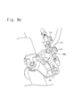
- Fig. 6 is a constructional perspective view showing a main part of the column-type shift lever structure in accordance with the embodiment of the present invention.
- Fig. 7 is a constructional perspective view showing a mode switch part of the column-type shift lever structure in accordance with the embodiment of the present invention.
- Figs. 8a and 8b are constructional views on an enlarged scale showing an upper switch and a select switch of the column-type shift lever structure in accordance with the preferred embodiment of the present invention, respectively;
- Figs. 9a and 9b are a constructional view for explaining a guide plate structure of the column-type shift lever structure in accordance with the embodiment of the present invention and a plan view of a guide plate of the guide plate structure;
- Fig. 10 is a constructional perspective view showing circuitry layout of the column-type shift lever structure in accordance with the embodiment of the present invention.
- Fig. 11 is a constructional perspective view showing a column-type shift lever structure in accordance with another embodiment of the present invention.
- Fig. 12 is a constructional perspective view showing a main part of the column-type shift lever structure in accordance with the embodiment of the present invention.
- Fig. 13 is a constructional perspective view showing a switch part of the column-type shift lever structure in accordance with the embodiment of the present invention.
- Figs. 14a and 14b are constructional perspective views in an enlarged scale showing an upper switch and a select switch of the column-type shift lever structure in accordance with the embodiment of the present invention
- Fig. 15 is a plan view of a guide plate of the column-type shift lever structure in accordance with the present invention.
- Fig. 16 is a constructional perspective view showing circuitry layout of the column-type shift lever structure in accordance with the present invention.
- Fig. 5 is a constructional perspective view of a column-type shift lever structure in accordance with one preferred embodiment of the present invention
- Fig. 6 is a constructional perspective view showing a main part of the column-type shift lever structure in accordance with the embodiment of the present invention
- Fig. 7 is a constructional perspective view showing a mode switch part of the column-type shift lever structure in accordance with the embodiment of the present invention
- Figs. 8a and 8b are constructional views on an enlarged scale showing an upper switch and a select switch of the column-type shift lever structure in accordance with the preferred embodiment of the present invention, respectively, Figs.
- FIG. 9a and 9b are a constructional view for explaining a guide plate structure of the column-type shift lever structure in accordance with the embodiment of the present invention and a plan view of a guide plate of the guide plate structure
- Fig. 10 is a constructional perspective view showing circuitry layout of the column-type shift lever structure in accordance with the embodiment of the present invention.
- a basic structure of the column-type shift lever structure in accordance with this embodiment of the present invention is the same as that of the conventional column-type shift lever structure as described above, but the mode switch part 170 for sensing upward and downward pivoting of the shift lever 110 in a manual shifting mode is further provided in the present invention and the guide plate is formed with locking jaws suitable to the structure in accordance with the present invention.
- the mode switch part 170 for sensing upward and downward pivoting of the shift lever 110 in a manual shifting mode is further provided in the present invention and the guide plate is formed with locking jaws suitable to the structure in accordance with the present invention.
- the column-type shift lever structure in accordance with this embodiment generally comprises a shift lever 110, an upper plate 120, a lower plate 130, a mode switch part 170, a cable actuating lever 140, a T/M control cable 160 and the like.
- Such a shift lever structure is applied to an automatic transmission having shifting ranges of P-R-N-D.
- the mode switch part 170 is operated in such a manner that it senses upward and downward pivoting of the shift lever 110 and transmits its sensing signals to a TCU (Transmission Control Unit) 100 when the shift lever 110 passes to a manual shifting mode position set up in a position next to range D, thereby enabling a driver to control the current shift stage of the automatic transmission by means of his shift lever operation.
- TCU Transmission Control Unit
- the mode switch part 170 senses this driver's operation as an upshift or a downshift, respectively and transmits its sensing signal to the TCU 100. In this way, the gear shifting is effected.
- the mode switch part 170 comprises an upper switch 174, a lower switch 176 and a select switch 172 for sensing upward pivoting of the shift lever, downward pivoting of the shift lever and passage of the shift lever from position D to the manual shifting mode position, respectively.
- the mode switch part 170 is fixedly provided in a proper position on a steering shaft side.
- the upper and lower switches 174, 176 and the select switch 172 are fixed to upper and lower portions and a side portion within the mode switch part 170, respectively. If the shift lever 110 passes to the manual shifting mode position, an actuating member 172a (elastic member) of the select switch 172 is pressed by a switch sensing member 111 formed on the shift lever 110 to turn on the select switch 172.
- an actuating rod 174a of the upper switch 174 is moved upward by the switch sensing member 111 while an end portion of the actuating rod 174a, whose diameter is larger than those of the other portions, presses the upper switch 174, so that the upper switch 174 is turned on.
- the actuating rod 174a is resiliently supported by a return spring 174b, which is fixed by a fixing member 174c, so as to be returned to its original position after it is moved upward.
- the lower switch 176 also has the same construction as that of the upper switch 174.
- the upper and lower switches 174, 176 and the select switch 172 of the mode switch part 170 are connected to their relevant signal parts of the TCU 100, respectively.
- the guide plate 132 attached to the lower plate 130 is formed with locking jaws for differentiating the respective shift stages from each other in a similar manner to in the conventional column-type shift lever structure.
- a locking jaw 132a for preventing direct passage of the shift lever 110 from range D to the manual shifting mode and thus false operation's occurrence is formed in a position next to range D. Since the shift lever 110 is caught by the locking jaw 132a, the shift lever 110 will not rotated from range D to the manual shifting mode only by the lever rotation, but can be rotated only after it is pushed upward.
- the shift lever structure in accordance with this embodiment is operated as follows:
- the select switch 172 of the mode switch part 170 is actuated to be turned on and thus the TCU 100 perceives the conversion from the driving mode to the manual shifting mode to fix a shift stage to the current shift stage. That is, the TCU 100 does not perform automatic shifting control according to vehicle speed and throttle position, but causes the gear shifting to be effected only by signals from the mode switch part 170.
- the mode switch part 170 senses upward or downward movement of the switch sensing member 111 and transmits its sensing signal to the TCU 100, the gear shifting is effected by the transmitted signal.
- the shift lever 110 can be freely pivoted to actuate the mode switch part 170.
- the select switch 172 is "OFF" and the TCU 100 perceives this to convert the transmission from the manual shifting mode to the driving mode again and to automatically control the gear shifting according to vehicle speed and throttle position.
- Fig. 11 is a constructional perspective view showing a column-type shift lever structure in accordance with another embodiment of the present invention
- Fig. 12 is a constructional perspective view showing a main part of the column-type shift lever structure in accordance with the embodiment of the present invention
- Fig. 13 is a constructional perspective view showing a switch part of the column-type shift lever structure in accordance with the embodiment of the present invention
- Figs. 14a and 14b are constructional perspective views in an enlarged scale showing an upper switch and a select switch of the column-type shift lever structure in accordance with the embodiment of the present invention
- Fig. 15 is a plan view of a guide plate of the column-type shift lever structure in accordance with the present invention
- Fig. 16 is a constructional perspective view showing circuitry layout of the column-type shift lever structure in accordance with the present invention.
- a shift lever 210 is provided with a select switch 280 for transmitting a signal causing the transmission to be converted from a driving mode D to a manual shifting mode M or vice versa to a TCU 100, and a switch part 270 is provided for sensing the upward and downward pivoting operations of the shift lever as upward and downward shifting signals, respectively in a state when the transmission is converted from the driving mode D to the manual shifting mode M.
- the column-type shift lever structure in accordance with this embodiment generally comprises a shift lever 210, a select switch 280, an upper plate 220, a lower plate 230, a switch part 270, a cable actuating lever 240, a T/M control cable 260 and the like.
- Such a shift lever structure is applied to an automatic transmission having shifting ranges of P-R-N-D.
- the select switch 280 which is operated in a state when the shift lever 210 is positioned in the driving mode (range D), causes the transmission to be converted from the driving mode to the manual shifting mode or vice versa.
- the select switch 280 is mounted to a knob 214 of the shift lever 210, and is so constructed that a switch wire 282 is drawn out through an inner hollow portion of the shift lever 210.
- the select switch 280 is turned on when a driver pushes down it once and is turn off when the driver pushes down it once more and thus it is returned to its original position.
- the select switch 280 transmit a signal causing the transmission to be converted from the driving mode D to the manual mode M when it is "ON”, and transmits a signal causing the transmission to be inversely converted when it is "OFF".
- the switch part 270 is operated in a state when the shift lever 210 passes from a position of range D to the manual shifting mode position and in such a manner that it senses upward and downward pivoting of the shift lever 210 and transmits its sensing signals to the TCU 100, thereby enabling a driver to control the current shift stage of the automatic transmission by means of his shift lever operation.
- the switch part 270 senses this driver's operation as an upshift or downshift, respectively and transmits its sensing signal to the TCU 100. In this way, the gear shifting is effected.
- the switch part 270 comprises an upper switch 274 and a lower switch 276 for sensing upward pivoting of the shift lever and downward pivoting of the shift lever, respectively.
- the switch part 270 is fixedly provided in a proper position on a steering shaft side.
- the upper and lower switches 274, 276 are fixed to upper and lower portions within the switch part 270, respectively. If the shift lever 210 is so operated as to be pivoted upward, an actuating rod 274a of the upper switch 274 is moved upward by the switch sensing member 211 formed on the shift lever 210 while an end portion of the actuating rod 274a, whose diameter is larger than those of the other portions, presses the upper switch 274, so that the upper switch 274 is turned on.
- the actuating rod 274a is resiliently supported by a return spring 274b, which is fixed by a fixing member 274c, so as to be returned to its original position after it is moved upward.
- the lower switch 276 also has the same construction as that of the upper switch 274.
- the upper and lower switches 274, 276 of the switch part 270 and the select switch 280 are connected to their relevant signal parts of the TCU 100, respectively.
- the guide plate 232 attached to the lower plate 230 is formed with locking jaws for differentiating the respective shift stages from each other in a similar manner to in the conventional column-type shift lever structure.
- any other range than ranges P-R-N-D such as ranges 3-2-L, are not necessary because the column-type shift lever structure of the present invention is provided with the manual shifting mode, by reason of which the guide plate 232 in accordance with this embodiment only has to include locking jaws for differentiating ranges P-R-N-D.
- a cluster 290 is provided for showing the current shifting range and the cluster 290 essentially has indication lamps for indicating the respective shifting ranges of P-R-N-D.
- the cluster 290 is provided with an indication lamp for indicating the manual shifting mode (M). Since the indication lamp for the driving mode (D) is not lighted and the indication lamp for the manual shifting mode (M) is lighted when the select switch is "ON”, and vice versa when the select switch is "OFF", the driver can easily recognize the current mode.
- the shift lever structure in accordance with this embodiment is operated as follows:
- the TCU 100 perceives the conversion from the driving mode to the manual shifting mode to fix a shift stage to the current shift stage. That is, the TCU 100 does not perform automatic shifting control according to vehicle speed and throttle position, but causes the gear shifting to be effected only by signals from the switch part 270.
- the shift lever 210 can be freely pivoted to actuate the switch part 170.
- the select switch 280 is rendered "OFF" and the TCU 100 perceives this to convert the transmission from the manual shifting mode to the driving mode and to automatically control the gear shifting according to vehicle speed and throttle position.
- a column-type shift lever structure for an automatic transmission with a manual shifting mode in accordance with the present invention permits a diver to manually shift a gear at his convenience even in an automatic transmission vehicle employing the column-type shift, thus providing more dynamic driving feel and improving performance and convenience of the vehicle.
Landscapes
- Engineering & Computer Science (AREA)
- General Engineering & Computer Science (AREA)
- Mechanical Engineering (AREA)
- Arrangement Or Mounting Of Control Devices For Change-Speed Gearing (AREA)
- Control Of Transmission Device (AREA)
Abstract
Description
- The present invention relates to a column-type shift lever structure for an automatic transmission with a manual shifting mode, and more particularly to a column-type shift lever structure applied to an automatic transmission vehicle, which is improved into a structure permitting a manual shifting mode, thus allowing a driver to enjoy dynamic driving feel by virtue of the manual shifting mode even in an automatic transmission vehicle with a column-type shift lever mounted thereto.
- A shift lever for handling a vehicle transmission is largely divided into a floor mounting-type shift lever installed on a floor side of a vehicle driver's seat and a column-type shift lever installed on a steering column adjacent to a vehicle steering wheel.
- Fig. 1 is a constructional perspective view showing one example of a conventional column-type shift lever structure, Fig. 2 is a constructional perspective view showing one example of a detent structure of a conventional column-type shift lever, Fig. 3 is a constructional perspective view showing one example of a guide plate structure of a conventional column-type shift lever, and Fig. 4 is a constructional perspective view showing one example of operational conditions of a conventional column-type shift lever. Hereinafter, one example of the conventional column-type shift lever structure for an automatic transmission will be described with reference to these drawings.
- Looking at the illustrated column-type shift lever structure, the column-type shift lever structure includes a
shift lever 10, anupper plate 20, alower plate 30, a cable actuatinglever 40 and a T/M control cable 60. - The
shift lever 10 enables a driver to perform shifting operations and is rotationally fixed to theupper plate 20. Theupper plate 20 is formed with aball joint 22 for rotating a cable actuatinglever 40. - The
lower plate 30, which is disposed on a lower face side of theupper plate 20, controls operation of each shift stage and is provided with a detent part for giving detent feel. The cable actuatinglever 40 is installed on thelower plate 30 to actuate the T/M control cable 60 by means of the rotation of theball joint 22. The T/M control cable 60 rotates a manual shaft on a T/M side as theshift lever 10 is operated. - In shifting operations of the conventional column-type shift lever thus constructed, for example, a shifting process from position P to position R is as follows:
- As shown in Fig. 4, the shift stages of the
shift lever 10 are so constructed that they progress in clockwise order of P R N D 3 2 L. If a driver rotates theshift lever 10 by a predetermined angle starting from position P (an angle toward position R), theball joint 22 of theupper plate 20 is rotated around a center axis of the steering wheel. - At this time, the cable actuating
lever 40 connected to theball joint 22 is rotated to pull the T/M control cable 60 and thus to rotate the manual shaft on the T/M side opposite to the cable side, by which the shifting operation is effected. The shifting operation in other ranges is achieved in the same manner. - Now, a description will be given for detail construction of each part of the column-type shift lever structure.
- Referring to Fig. 2, the column-type shift lever structure includes the detent part for giving detent feel. In order to give the detent feel upon rotation of the
shift lever 10, adetent spring portion 24 of theupper plate 20 is provided with a ball resiliently supported by a spring, and detentholes 34 in which the ball is engaged are formed on thelower plate 30 in a position corresponding to thedetent spring portion 24 and with a distance between the respective shifting positions. - As shown in Fig. 3, a
stopper 12 formed in a body portion of theshift lever 10 is constructed in such a manner that it is caught by locking jaws of aguide plate 32 when theshift lever 10 is rotated for the shifting, as a result of which theshift lever 10 must be pivoted upward before it is rotated at a preset shift stage. - That is, in a case of the
guide plate 32 as illustrated, theshift lever 10 cannot be rotated from position P to position R until it is pivoted upward. This is also applicable to a case when theshift lever 10 is rotated from position 3 toposition 2, fromposition 2 to position N or from position N to position R. - Meanwhile, vehicle transmissions are largely divided into manual transmission type and automatic transmission type. The manual transmission and the automatic transmission have their own advantages and disadvantages, respectively, on the basis of which they have been selectively installed and used according to driver's taste. Since it is difficult to handle the manual transmission compared with the automatic transmission and thus the manual transmission is inconvenient to a driver, a recent tendency is toward preferring a vehicle equipped with an automatic transmission.
- On the other hand, however, the manual transmission has an advantage in that a driver can perform gear shifting in accordance with vehicle's traveling conditions, so that the manual transmission has superior gas mileage over that of the automatic transmission and allows a driver to enjoy dynamic driving feel. For the sake of drivers preferring the convenience of the automatic transmission and the dynamic driving characteristic of the manual transmission, therefore, an automatic transmission with a manual shifting mode similar to the manual transmission's gear shifting has been recently come to be developed and used.
- Many automatic transmission structures with the manual shifting mode have been proposed for a vehicle with the floor mounting-type shift lever, but such an automatic transmission has scarcely been proposed for a vehicle with the column-type shift lever because it is structurally difficult to apply the manual shifting mode to the vehicle with the column-type shift lever, and some proposals even have a problem regarding unfavorable handling properties due to structural complexity or poor durability.
- Consequently, there is an earnest need for developing a column-type shift lever structure capable of applying the manual shifting mode thereto.
- Accordingly, the present invention has been created in order to solve the above-mentioned problems occurring in the prior art, and an object of the present invention is to provide a column-type shift lever structure applied to an automatic transmission vehicle, which is improved into a structure permitting a manual shifting mode, thus allowing a driver to enjoy dynamic driving feel by virtue of the manual shifting mode even in an automatic transmission vehicle with a column-type shift lever mounted thereto.
- To accomplish this object, there is provided a column-type shift lever structure for an automatic transmission in accordance with one aspect of the present invention, the shift lever structure comprising: an upper plate being rotated around a steering shaft by a shift lever; a lower plate being provided in a lower portion of the upper plate and having locking jaws which perform catching and releasing actions at each shifting position of a stopper formed on the shift lever when the shift lever is pivoted upward and downward; and a cable actuating lever being provided on the lower plate and being pivoted by a ball joint formed on the upper plate to actuate a T/M control cable, wherein the locking jaws are so constructed that the shift lever is rotated from a driving mode position to a manual shifting mode position, and a mode switch part is provided in the manual shifting mode position of the shift lever to sense the upward and downward pivoting operations of the shift lever as upward and downward shifting signals, respectively, and to transmit the signals to a TCU (Transmission Control Unit).
- Preferably, the mode switch part comprises a select switch for sensing the rotation of the shift lever from the driving mode position to the manual shifting mode position, and upper and lower switches for sensing upward and downward pivoting operations of the shift lever as upward and downward shifting signals, respectively.
- The select switch preferably transmits its sensing signal to the TCU to convert the transmission from the driving mode to the manual shifting mode when it senses the rotation of the shift lever from the driving mode position to the manual shifting mode position.
- Also, the locking jaws are preferably constructed in such a manner that the shift lever can be rotated only in a state of being pivoted upward when the shift lever is rotated from the driving mode position to the manual shifting mode position, thus preventing direct conversion from the driving mode to the manual shifting mode.
- It is preferred that the locking jaws are formed on a guide plate separately attached to the lower plate.
- In accordance with another aspect of the present invention, there is provided a shift lever structure for an automatic transmission comprising: an upper plate being rotated around a steering shaft by a shift lever; a lower plate being provided in a lower portion of the upper plate and having locking jaws which perform catching and releasing actions at each shifting position of a stopper formed on the shift lever when the shift lever is pivoted upward and downward; and a cable actuating lever being provided on the lower plate and being pivoted by a ball joint formed on the upper plate to actuate a T/M control cable, wherein a select switch is provided on the shift lever to transmit a signal for converting the transmission from a driving mode to a manual shifting mode or vice versa to a TCU when a driver operates the select switch, and a switch part is provided in the manual shifting mode position of the shift lever to sense the upward and downward pivoting operations of the shift lever as upward and downward shifting signals, respectively, and to transmit the signals to the TCU in a state when the transmission is converted from the driving mode to the manual shifting mode.
- Preferably, the select switch transmits a signal for converting the transmission from the driving mode to the manual shifting mode to the TCU when it is "ON" and transmits a signal for inversely converting the transmission to the TCU when it is "OFF".
- More preferably, the select switch is provided on a knob of the shift lever and is so constructed that a switch wire is drawn out through an inner hollow portion of the shift lever.
- The switch part preferably includes upper and lower switches for sensing upward and downward pivoting operations of the shift lever as upward and downward shifting signals, respectively.
- It is preferred that the shift lever structure of the present invention further comprises a cluster for indicating the current shifting range and the cluster is provided with indication lamps for indicating the driving mode and the manual shifting mode, respectively to show the current mode when the mode is converted by the select switch.
- Hereinafter, preferred embodiments of the present invention will be described in detail with reference to the accompanying drawings.
- Fig. 1 is a constructional perspective view showing one example of a conventional column-type shift lever structure;
- Fig. 2 is a constructional perspective view showing one example of a detent structure of the conventional column-type shift lever;
- Fig. 3 is a constructional perspective view showing one example of a guide plate structure of the conventional column-type shift lever;
- Fig. 4 is a constructional perspective view showing one example of operational conditions of the conventional column-type shift lever;
- Fig. 5 is a constructional perspective view of a column-type shift lever structure in accordance with one preferred embodiment of the present invention;
- Fig. 6 is a constructional perspective view showing a main part of the column-type shift lever structure in accordance with the embodiment of the present invention;
- Fig. 7 is a constructional perspective view showing a mode switch part of the column-type shift lever structure in accordance with the embodiment of the present invention;
- Figs. 8a and 8b are constructional views on an enlarged scale showing an upper switch and a select switch of the column-type shift lever structure in accordance with the preferred embodiment of the present invention, respectively;
- Figs. 9a and 9b are a constructional view for explaining a guide plate structure of the column-type shift lever structure in accordance with the embodiment of the present invention and a plan view of a guide plate of the guide plate structure;
- Fig. 10 is a constructional perspective view showing circuitry layout of the column-type shift lever structure in accordance with the embodiment of the present invention;
- Fig. 11 is a constructional perspective view showing a column-type shift lever structure in accordance with another embodiment of the present invention;
- Fig. 12 is a constructional perspective view showing a main part of the column-type shift lever structure in accordance with the embodiment of the present invention;
- Fig. 13 is a constructional perspective view showing a switch part of the column-type shift lever structure in accordance with the embodiment of the present invention;
- Figs. 14a and 14b are constructional perspective views in an enlarged scale showing an upper switch and a select switch of the column-type shift lever structure in accordance with the embodiment of the present invention;
- Fig. 15 is a plan view of a guide plate of the column-type shift lever structure in accordance with the present invention; and
- Fig. 16 is a constructional perspective view showing circuitry layout of the column-type shift lever structure in accordance with the present invention.
- Hereinafter, preferred embodiments of the present invention will be described in detail with reference to the accompanying drawings.
- Fig. 5 is a constructional perspective view of a column-type shift lever structure in accordance with one preferred embodiment of the present invention, Fig. 6 is a constructional perspective view showing a main part of the column-type shift lever structure in accordance with the embodiment of the present invention, Fig. 7 is a constructional perspective view showing a mode switch part of the column-type shift lever structure in accordance with the embodiment of the present invention, Figs. 8a and 8b are constructional views on an enlarged scale showing an upper switch and a select switch of the column-type shift lever structure in accordance with the preferred embodiment of the present invention, respectively, Figs. 9a and 9b are a constructional view for explaining a guide plate structure of the column-type shift lever structure in accordance with the embodiment of the present invention and a plan view of a guide plate of the guide plate structure, and Fig. 10 is a constructional perspective view showing circuitry layout of the column-type shift lever structure in accordance with the embodiment of the present invention.
- A basic structure of the column-type shift lever structure in accordance with this embodiment of the present invention is the same as that of the conventional column-type shift lever structure as described above, but the
mode switch part 170 for sensing upward and downward pivoting of theshift lever 110 in a manual shifting mode is further provided in the present invention and the guide plate is formed with locking jaws suitable to the structure in accordance with the present invention. In the following description and drawings, repetition of the description on the same or similar components will be omitted. - The column-type shift lever structure in accordance with this embodiment generally comprises a
shift lever 110, anupper plate 120, alower plate 130, amode switch part 170, acable actuating lever 140, a T/M control cable 160 and the like. - Such a shift lever structure is applied to an automatic transmission having shifting ranges of P-R-N-D. The
mode switch part 170 is operated in such a manner that it senses upward and downward pivoting of theshift lever 110 and transmits its sensing signals to a TCU (Transmission Control Unit) 100 when theshift lever 110 passes to a manual shifting mode position set up in a position next to range D, thereby enabling a driver to control the current shift stage of the automatic transmission by means of his shift lever operation. - That is, if the driver raises the
shift lever 110 upward and then lets it go or if the driver lowers theshift lever 110 downward and then lets it go, themode switch part 170 senses this driver's operation as an upshift or a downshift, respectively and transmits its sensing signal to theTCU 100. In this way, the gear shifting is effected. - The
mode switch part 170 comprises anupper switch 174, alower switch 176 and aselect switch 172 for sensing upward pivoting of the shift lever, downward pivoting of the shift lever and passage of the shift lever from position D to the manual shifting mode position, respectively. Themode switch part 170 is fixedly provided in a proper position on a steering shaft side. - The upper and
lower switches select switch 172 are fixed to upper and lower portions and a side portion within themode switch part 170, respectively. If theshift lever 110 passes to the manual shifting mode position, an actuatingmember 172a (elastic member) of theselect switch 172 is pressed by aswitch sensing member 111 formed on theshift lever 110 to turn on theselect switch 172. - If the
shift lever 110 is so operated as to be pivoted upward, anactuating rod 174a of theupper switch 174 is moved upward by theswitch sensing member 111 while an end portion of theactuating rod 174a, whose diameter is larger than those of the other portions, presses theupper switch 174, so that theupper switch 174 is turned on. - The
actuating rod 174a is resiliently supported by areturn spring 174b, which is fixed by a fixingmember 174c, so as to be returned to its original position after it is moved upward. Thelower switch 176 also has the same construction as that of theupper switch 174. - In order to transmit the shifting mode conversion signal and the shift stage control signal, the upper and
lower switches select switch 172 of themode switch part 170 are connected to their relevant signal parts of theTCU 100, respectively. - The
guide plate 132 attached to thelower plate 130 is formed with locking jaws for differentiating the respective shift stages from each other in a similar manner to in the conventional column-type shift lever structure. In particular, a lockingjaw 132a for preventing direct passage of theshift lever 110 from range D to the manual shifting mode and thus false operation's occurrence is formed in a position next to range D. Since theshift lever 110 is caught by the lockingjaw 132a, theshift lever 110 will not rotated from range D to the manual shifting mode only by the lever rotation, but can be rotated only after it is pushed upward. - The shift lever structure in accordance with this embodiment is operated as follows:
- If the
shift lever 110 passes from range D to the manual shifting mode as shown, theselect switch 172 of themode switch part 170 is actuated to be turned on and thus theTCU 100 perceives the conversion from the driving mode to the manual shifting mode to fix a shift stage to the current shift stage. That is, theTCU 100 does not perform automatic shifting control according to vehicle speed and throttle position, but causes the gear shifting to be effected only by signals from themode switch part 170. - Thereafter, if the
mode switch part 170 senses upward or downward movement of theswitch sensing member 111 and transmits its sensing signal to theTCU 100, the gear shifting is effected by the transmitted signal. - In the course when the
shift lever 110 passes from range D to the manual shifting mode, direct conversion from range D to the manual shifting mode is prevented by the locking jaw 32a formed on theguide plate 132 in a position next to range D. - Since there are no lower locking jaws as those provided in positions of the automatic shifting ranges after the
shift lever 100 passes to the manual shifting mode, theshift lever 110 can be freely pivoted to actuate themode switch part 170. - If the
shift lever 110 is rotated toward range D in order to pass from the manual shifting mode to the driving mode (range D), theselect switch 172 is "OFF" and theTCU 100 perceives this to convert the transmission from the manual shifting mode to the driving mode again and to automatically control the gear shifting according to vehicle speed and throttle position. - Next, a column-type shift lever structure in accordance with another embodiment of the present invention will be described.
- Fig. 11 is a constructional perspective view showing a column-type shift lever structure in accordance with another embodiment of the present invention, Fig. 12 is a constructional perspective view showing a main part of the column-type shift lever structure in accordance with the embodiment of the present invention, Fig. 13 is a constructional perspective view showing a switch part of the column-type shift lever structure in accordance with the embodiment of the present invention, Figs. 14a and 14b are constructional perspective views in an enlarged scale showing an upper switch and a select switch of the column-type shift lever structure in accordance with the embodiment of the present invention, Fig. 15 is a plan view of a guide plate of the column-type shift lever structure in accordance with the present invention, and Fig. 16 is a constructional perspective view showing circuitry layout of the column-type shift lever structure in accordance with the present invention.
- In the column-type shift lever structure in accordance with this embodiment of the present invention, a
shift lever 210 is provided with aselect switch 280 for transmitting a signal causing the transmission to be converted from a driving mode D to a manual shifting mode M or vice versa to aTCU 100, and aswitch part 270 is provided for sensing the upward and downward pivoting operations of the shift lever as upward and downward shifting signals, respectively in a state when the transmission is converted from the driving mode D to the manual shifting mode M. - The column-type shift lever structure in accordance with this embodiment generally comprises a
shift lever 210, aselect switch 280, anupper plate 220, alower plate 230, aswitch part 270, acable actuating lever 240, a T/M control cable 260 and the like. - Such a shift lever structure is applied to an automatic transmission having shifting ranges of P-R-N-D. The
select switch 280, which is operated in a state when theshift lever 210 is positioned in the driving mode (range D), causes the transmission to be converted from the driving mode to the manual shifting mode or vice versa. - The
select switch 280 is mounted to aknob 214 of theshift lever 210, and is so constructed that aswitch wire 282 is drawn out through an inner hollow portion of theshift lever 210. Theselect switch 280 is turned on when a driver pushes down it once and is turn off when the driver pushes down it once more and thus it is returned to its original position. - By this construction of the
select switch 280, theselect switch 280 transmit a signal causing the transmission to be converted from the driving mode D to the manual mode M when it is "ON", and transmits a signal causing the transmission to be inversely converted when it is "OFF". - The
switch part 270 is operated in a state when theshift lever 210 passes from a position of range D to the manual shifting mode position and in such a manner that it senses upward and downward pivoting of theshift lever 210 and transmits its sensing signals to theTCU 100, thereby enabling a driver to control the current shift stage of the automatic transmission by means of his shift lever operation. - That is, if the driver raises the
shift lever 210 upward and then lets it go or if the driver lowers theshift lever 210 downward and then lets it go, theswitch part 270 senses this driver's operation as an upshift or downshift, respectively and transmits its sensing signal to theTCU 100. In this way, the gear shifting is effected. - The
switch part 270 comprises anupper switch 274 and alower switch 276 for sensing upward pivoting of the shift lever and downward pivoting of the shift lever, respectively. Theswitch part 270 is fixedly provided in a proper position on a steering shaft side. - The upper and
lower switches switch part 270, respectively. If theshift lever 210 is so operated as to be pivoted upward, anactuating rod 274a of theupper switch 274 is moved upward by theswitch sensing member 211 formed on theshift lever 210 while an end portion of theactuating rod 274a, whose diameter is larger than those of the other portions, presses theupper switch 274, so that theupper switch 274 is turned on. - The
actuating rod 274a is resiliently supported by areturn spring 274b, which is fixed by a fixingmember 274c, so as to be returned to its original position after it is moved upward. Thelower switch 276 also has the same construction as that of theupper switch 274. - In order to transmit the shifting mode conversion signal and the shift stage control signal, the upper and
lower switches switch part 270 and theselect switch 280 are connected to their relevant signal parts of theTCU 100, respectively. - The
guide plate 232 attached to thelower plate 230 is formed with locking jaws for differentiating the respective shift stages from each other in a similar manner to in the conventional column-type shift lever structure. On the contrary to the conventional column-type shift lever structure, any other range than ranges P-R-N-D, such as ranges 3-2-L, are not necessary because the column-type shift lever structure of the present invention is provided with the manual shifting mode, by reason of which theguide plate 232 in accordance with this embodiment only has to include locking jaws for differentiating ranges P-R-N-D. - In a vehicle to which the
shift lever 210 in accordance with this embodiment is mounted, acluster 290 is provided for showing the current shifting range and thecluster 290 essentially has indication lamps for indicating the respective shifting ranges of P-R-N-D. - Besides the indication lamp for indicating the driving mode (D), the
cluster 290 is provided with an indication lamp for indicating the manual shifting mode (M). Since the indication lamp for the driving mode (D) is not lighted and the indication lamp for the manual shifting mode (M) is lighted when the select switch is "ON", and vice versa when the select switch is "OFF", the driver can easily recognize the current mode. - The shift lever structure in accordance with this embodiment is operated as follows:
- If the
select switch 280 is turned on in a state when theshift lever 210 is positioned in range D, theTCU 100 perceives the conversion from the driving mode to the manual shifting mode to fix a shift stage to the current shift stage. That is, theTCU 100 does not perform automatic shifting control according to vehicle speed and throttle position, but causes the gear shifting to be effected only by signals from theswitch part 270. - Thereafter, if the
switch part 270 senses upward or downward movement of theswitch sensing member 111 and transmits its sensing signal to theTCU 100, the gear shifting is effected by the transmitted signal. - Since there are no lower locking jaws preventing the downward pivoting of the
shift lever 210 in the manual shifting mode position, theshift lever 210 can be freely pivoted to actuate theswitch part 170. - In order to convert the transmission from the driving mode (range D) to the manual shifting mode (M) again, the
select switch 280 is rendered "OFF" and theTCU 100 perceives this to convert the transmission from the manual shifting mode to the driving mode and to automatically control the gear shifting according to vehicle speed and throttle position. - As stated above, a column-type shift lever structure for an automatic transmission with a manual shifting mode in accordance with the present invention permits a diver to manually shift a gear at his convenience even in an automatic transmission vehicle employing the column-type shift, thus providing more dynamic driving feel and improving performance and convenience of the vehicle.
- Although preferred embodiments of the present invention have been described for illustrative purposes, those skilled in the art will appreciate that various modifications, additions and substitutions are possible, without departing from the scope and spirit of the invention as disclosed in the accompanying claims.
Claims (11)
- A column-type shift lever structure for an automatic transmission with a manual shifting mode comprising:wherein the locking jaws are so constructed that the shift lever is rotated from a driving mode position to a manual shifting mode position, and a mode switch part is provided in the manual shifting mode position of the shift lever to sense the upward and downward pivoting operations of the shift lever as upward and downward shifting signals, respectively, and to transmit the signals to a TCU (Transmission Control Unit).an upper plate being rotated around a steering shaft by a shift lever;a lower plate being provided in a lower portion of the upper plate and having locking jaws which perform catching and releasing actions at each shifting position of a stopper formed on the shift lever when the shift lever is pivoted upward and downward; anda cable actuating lever being provided on the lower plate and being pivoted by a ball joint formed on the upper plate to actuate a T/M control cable,
- A column-type shift lever structure according to claim 1, wherein the mode switch part comprises a select switch for sensing the rotation of the shift lever from the driving mode position to the manual shifting mode position, and upper and lower switches for sensing the upward and downward pivoting operations of the shift lever as the upward and downward shifting signals, respectively.
- A column-type shift lever structure according to claim 2, wherein the select switch transmits its sensing signal to the TCU to convert the transmission from the driving mode to the manual shifting mode when it senses the rotation of the shift lever from the driving mode position to the manual shifting mode position.
- A column-type shift lever structure according to any one of claims 1 to 3, wherein the locking jaws are constructed in such a manner that the shift lever can be rotated only in a state of being pivoted upward when the shift lever is rotated from the driving mode position to the manual shifting mode position, thus preventing direct conversion from the driving mode to the manual shifting mode.
- A column-type shift lever structure according to claim 4, wherein the locking jaws are formed on a guide plate separately attached to the lower plate.
- A column-type shift lever structure for an automatic transmission with a manual shifting mode comprising:wherein a select switch is provided on the shift lever to transmit a signal for converting the transmission from a driving mode to a manual shifting mode or vice versa to a TCU when a driver operates the select switch, and a switch part is provided in the manual shifting mode position of the shift lever to sense the upward and downward pivoting operations of the shift lever as upward and downward shifting signals, respectively, and to transmit the signals to the TCU in a state when the transmission is converted from the driving mode to the manual shifting mode.an upper plate being rotated around a steering shaft by a shift lever;a lower plate being provided in a lower portion of the upper plate and having locking jaws which perform catching and releasing actions at each shifting position of a stopper formed on the shift lever when the shift lever is pivoted upward and downward; anda cable actuating lever being provided on the lower plate and being pivoted by a ball joint formed on the upper plate to actuate a T/M control cable,
- A column-type shift lever structure according to claim 6, wherein the select switch transmits a signal for converting the transmission from the driving mode to the manual shifting mode to the TCU when it is "ON" and transmits a signal for inversely converting the transmission to the TCU when it is "OFF".
- A column-type shift lever structure according to claim 6, wherein the select switch is provided on a knob of the shift lever and is so constructed that a switch wire is drawn out through an inner hollow portion of the shift lever.
- A column-type shift lever structure according to claim 6, wherein the switch part includes upper and lower switches for sensing the upward and downward pivoting operations of the shift lever as the upward and downward shifting signals, respectively.
- A column-type shift lever structure according to claim 6, wherein the shift lever structure further comprises a cluster for indicating the current shifting range and the cluster is provided with indication lamps for indicating the driving mode and the manual shifting mode, respectively to show the current mode when the mode is converted by the select switch.
- A column-type shift lever structure for an automatic transmission with a manual shifting mode comprising:wherein the shift lever can be rotated to a predetermined manual shifting mode set up by the lower plate, a select switch is provided for transmitting a signal causing the transmission to be converted from a driving mode to a manual shifting mode or vice versa to a TCU, and a switch part is provided in the manual shifting mode position of the shift lever to sense the upward and downward pivoting operations of the shift lever as upward and downward shifting signals, respectively, and to transmit the signals to the TCU.an upper plate being rotated around a steering shaft by a shift lever;a lower plate being provided in a lower portion of the upper plate and having locking jaws which perform catching and releasing actions at each shifting position of a stopper formed on the shift lever when the shift lever is pivoted upward and downward; anda cable actuating lever being provided on the lower plate and being pivoted by a ball joint formed on the upper plate to actuate a T/M control cable,
Applications Claiming Priority (4)
| Application Number | Priority Date | Filing Date | Title |
|---|---|---|---|
| KR10-2002-0021724A KR100461832B1 (en) | 2002-04-20 | 2002-04-20 | Structure of column-type shift lever for automatic transmission with manual mode |
| KR10-2002-0021725A KR100461833B1 (en) | 2002-04-20 | 2002-04-20 | Structure of column-type shift lever for automatic transmission with manual mode |
| KR2002021725 | 2002-04-20 | ||
| KR2002021724 | 2002-04-20 |
Publications (2)
| Publication Number | Publication Date |
|---|---|
| EP1355088A1 true EP1355088A1 (en) | 2003-10-22 |
| EP1355088B1 EP1355088B1 (en) | 2008-12-10 |
Family
ID=28677694
Family Applications (1)
| Application Number | Title | Priority Date | Filing Date |
|---|---|---|---|
| EP03000679A Expired - Fee Related EP1355088B1 (en) | 2002-04-20 | 2003-01-16 | Column-type shift lever structure for automatic transmission with manual shifting mode |
Country Status (4)
| Country | Link |
|---|---|
| US (1) | US6945132B2 (en) |
| EP (1) | EP1355088B1 (en) |
| JP (1) | JP2003312301A (en) |
| DE (1) | DE60325133D1 (en) |
Cited By (2)
| Publication number | Priority date | Publication date | Assignee | Title |
|---|---|---|---|---|
| GB2399606A (en) * | 2002-09-04 | 2004-09-22 | Ford Global Tech Llc | Motor vehicle transmission selector mechanisms |
| US10100919B1 (en) | 2016-06-10 | 2018-10-16 | Kongsberg Power Products Systems I, Inc. | Shifter assembly |
Families Citing this family (19)
| Publication number | Priority date | Publication date | Assignee | Title |
|---|---|---|---|---|
| KR100461832B1 (en) * | 2002-04-20 | 2004-12-14 | 기아자동차주식회사 | Structure of column-type shift lever for automatic transmission with manual mode |
| US20050274217A1 (en) * | 2004-05-27 | 2005-12-15 | Dubay Kurt D | Transmission gear selector switch on shift lever |
| JP4937861B2 (en) * | 2007-08-27 | 2012-05-23 | 株式会社東海理化電機製作所 | Column shift switch device |
| US8246515B2 (en) * | 2009-02-27 | 2012-08-21 | Ruimin Zhao | Method for manually shifting an automatic transmission through the accelerator pedal |
| US9377100B2 (en) | 2012-07-06 | 2016-06-28 | Kongsberg Automotive Ab | Shifter assembly |
| CN105257678A (en) * | 2015-11-02 | 2016-01-20 | 重庆御捷汽车部件有限公司 | Automobile gear shifting inhaul cable assembly with friction reducing structure |
| CN105240390A (en) * | 2015-11-02 | 2016-01-13 | 重庆御捷汽车部件有限公司 | Automobile gear shifting inhaul cable with friction reduction and interference sealing structure |
| CN105240393A (en) * | 2015-11-02 | 2016-01-13 | 重庆御捷汽车部件有限公司 | Automobile gear shifting inhaul cable with friction reduction steel wire and interference sealing structure |
| CN105240391A (en) * | 2015-11-02 | 2016-01-13 | 重庆御捷汽车部件有限公司 | Automobile gear shifting inhaul cable with internal friction and shock reducing structure and external friction and shock reducing structure |
| CN105221555A (en) * | 2015-11-02 | 2016-01-06 | 重庆御捷汽车部件有限公司 | There is the automobile gear shifting inhaul cable assembly of interference seal, noise reduction and shock-damping structure |
| CN105257679A (en) * | 2015-11-02 | 2016-01-20 | 重庆御捷汽车部件有限公司 | Automobile gear shifting inhaul cable with antifriction steel wire rope and shock absorption structure |
| CN105221556A (en) * | 2015-11-02 | 2016-01-06 | 重庆御捷汽车部件有限公司 | There is the automobile gear shifting inhaul cable assembly of interference seal and shock-damping structure |
| CN105240392A (en) * | 2015-11-02 | 2016-01-13 | 重庆御捷汽车部件有限公司 | Vehicle gear shifting stay rope assembly having noise reducing structure |
| CN105299025A (en) * | 2015-11-02 | 2016-02-03 | 重庆御捷汽车部件有限公司 | Automobile gear shifting inhaul cable with antifriction, shock absorption and dust prevention function |
| CN105605079A (en) * | 2015-11-02 | 2016-05-25 | 重庆御捷汽车部件有限公司 | Automobile gearshift cable assembly |
| US10072751B2 (en) * | 2016-05-17 | 2018-09-11 | Dura Operating, Llc | Vehicle shifter with offset cable actuator |
| US20170335957A1 (en) * | 2016-05-17 | 2017-11-23 | Dura Operating, Llc | Transmission shifter with multi-position lockout |
| JP7409601B2 (en) * | 2018-01-05 | 2024-01-09 | 株式会社東海理化電機製作所 | shift device |
| CN114857252B (en) * | 2022-05-06 | 2023-09-19 | 岚图汽车科技有限公司 | Electronic gear shifter integrating whole vehicle light control function and control method |
Citations (3)
| Publication number | Priority date | Publication date | Assignee | Title |
|---|---|---|---|---|
| US5280732A (en) * | 1991-11-26 | 1994-01-25 | Toyota Jidosha Kabushiki Kaisha | Column type change lever mechanism for automatic transmission in automotive vehicle |
| EP0725237A1 (en) * | 1995-02-01 | 1996-08-07 | Honda Giken Kogyo Kabushiki Kaisha | Control system for automatic transmission for vehicle |
| US5865705A (en) * | 1996-03-19 | 1999-02-02 | Kabushiki Kaisha Tokai-Rika-Denki-Seisakusho | Operating apparatus for automatic transmission |
Family Cites Families (3)
| Publication number | Priority date | Publication date | Assignee | Title |
|---|---|---|---|---|
| US4966044A (en) * | 1989-05-30 | 1990-10-30 | J. I. Case Company | Directional control system for a tractor transmission |
| JP3358984B2 (en) * | 1997-12-26 | 2002-12-24 | 株式会社アツミテック | Column shift device for automatic transmission |
| JP2001006493A (en) * | 1999-06-16 | 2001-01-12 | Sumitomo Wiring Syst Ltd | Mounting structure of cable reel and winker.lighting switch on steering shaft |
-
2003
- 2003-01-16 EP EP03000679A patent/EP1355088B1/en not_active Expired - Fee Related
- 2003-01-16 JP JP2003008878A patent/JP2003312301A/en active Pending
- 2003-01-16 DE DE60325133T patent/DE60325133D1/en not_active Expired - Lifetime
- 2003-02-28 US US10/378,577 patent/US6945132B2/en not_active Expired - Fee Related
Patent Citations (3)
| Publication number | Priority date | Publication date | Assignee | Title |
|---|---|---|---|---|
| US5280732A (en) * | 1991-11-26 | 1994-01-25 | Toyota Jidosha Kabushiki Kaisha | Column type change lever mechanism for automatic transmission in automotive vehicle |
| EP0725237A1 (en) * | 1995-02-01 | 1996-08-07 | Honda Giken Kogyo Kabushiki Kaisha | Control system for automatic transmission for vehicle |
| US5865705A (en) * | 1996-03-19 | 1999-02-02 | Kabushiki Kaisha Tokai-Rika-Denki-Seisakusho | Operating apparatus for automatic transmission |
Cited By (4)
| Publication number | Priority date | Publication date | Assignee | Title |
|---|---|---|---|---|
| GB2399606A (en) * | 2002-09-04 | 2004-09-22 | Ford Global Tech Llc | Motor vehicle transmission selector mechanisms |
| GB2399606B (en) * | 2002-09-04 | 2005-11-30 | Ford Global Tech Llc | Motor vehicle transmission selector mechanisms |
| US10100919B1 (en) | 2016-06-10 | 2018-10-16 | Kongsberg Power Products Systems I, Inc. | Shifter assembly |
| US10190675B2 (en) | 2016-06-10 | 2019-01-29 | Kongsberg Power Products Systems I, Inc. | Shifter assembly |
Also Published As
| Publication number | Publication date |
|---|---|
| US20030196507A1 (en) | 2003-10-23 |
| EP1355088B1 (en) | 2008-12-10 |
| JP2003312301A (en) | 2003-11-06 |
| DE60325133D1 (en) | 2009-01-22 |
| US6945132B2 (en) | 2005-09-20 |
Similar Documents
| Publication | Publication Date | Title |
|---|---|---|
| EP1355088B1 (en) | Column-type shift lever structure for automatic transmission with manual shifting mode | |
| EP1304507B1 (en) | Manual gearshift device for automotive automatic transmission | |
| US5509322A (en) | Shift control mechanism to manually shift an automatic transmission | |
| US6230579B1 (en) | Multi-mode shifter assembly joint | |
| JPH11141663A (en) | Control device for automatic transmission of automobile | |
| JP2003518464A (en) | Vehicle control device | |
| US3465612A (en) | Remote control linkage mechanism for a multiple ratio power transmission system | |
| US20050235769A1 (en) | Shift-by-wire shifting with P position | |
| JP3447482B2 (en) | Speed change device for vehicle | |
| US5799539A (en) | Manually shifted automatic transmission lever | |
| US20060169085A1 (en) | Drive train comprising a device for selecting driving mode ranges of an automated manual transmission or automatic tansmission of a motor vehicle | |
| US5946976A (en) | Shifting arrangement for automatic transmission | |
| JP3718646B2 (en) | Switch device | |
| US7367420B1 (en) | All terrain vehicle (ATV) having a rider interface for electronic or mechanical shifting | |
| US5870929A (en) | Gear-shift device for an automatic gearbox | |
| JP3477326B2 (en) | Transmission operation device for automatic transmission | |
| KR100461832B1 (en) | Structure of column-type shift lever for automatic transmission with manual mode | |
| JPS63158621A (en) | Tiltable shift lever device for automatic transmission | |
| KR100461833B1 (en) | Structure of column-type shift lever for automatic transmission with manual mode | |
| US5806368A (en) | Gearshift device for a semiautomatically shiftable change-speed gearbox | |
| JPH0438129Y2 (en) | ||
| JPH0412272Y2 (en) | ||
| JP2003127696A (en) | Switch device | |
| JPS6233637Y2 (en) | ||
| JP4633385B2 (en) | Transmission change mechanism |
Legal Events
| Date | Code | Title | Description |
|---|---|---|---|
| PUAI | Public reference made under article 153(3) epc to a published international application that has entered the european phase |
Free format text: ORIGINAL CODE: 0009012 |
|
| AK | Designated contracting states |
Kind code of ref document: A1 Designated state(s): AT BE BG CH CY CZ DE DK EE ES FI FR GB GR HU IE IT LI LU MC NL PT SE SI SK TR |
|
| AX | Request for extension of the european patent |
Extension state: AL LT LV MK RO |
|
| 17P | Request for examination filed |
Effective date: 20040422 |
|
| AKX | Designation fees paid |
Designated state(s): DE |
|
| 17Q | First examination report despatched |
Effective date: 20080108 |
|
| GRAP | Despatch of communication of intention to grant a patent |
Free format text: ORIGINAL CODE: EPIDOSNIGR1 |
|
| GRAS | Grant fee paid |
Free format text: ORIGINAL CODE: EPIDOSNIGR3 |
|
| GRAA | (expected) grant |
Free format text: ORIGINAL CODE: 0009210 |
|
| AK | Designated contracting states |
Kind code of ref document: B1 Designated state(s): DE |
|
| REF | Corresponds to: |
Ref document number: 60325133 Country of ref document: DE Date of ref document: 20090122 Kind code of ref document: P |
|
| PLBE | No opposition filed within time limit |
Free format text: ORIGINAL CODE: 0009261 |
|
| STAA | Information on the status of an ep patent application or granted ep patent |
Free format text: STATUS: NO OPPOSITION FILED WITHIN TIME LIMIT |
|
| 26N | No opposition filed |
Effective date: 20090911 |
|
| PGFP | Annual fee paid to national office [announced via postgrant information from national office to epo] |
Ref country code: DE Payment date: 20100114 Year of fee payment: 8 |
|
| REG | Reference to a national code |
Ref country code: DE Ref legal event code: R119 Ref document number: 60325133 Country of ref document: DE Effective date: 20110802 |
|
| PG25 | Lapsed in a contracting state [announced via postgrant information from national office to epo] |
Ref country code: DE Free format text: LAPSE BECAUSE OF NON-PAYMENT OF DUE FEES Effective date: 20110802 |