EP1354703A2 - Bogenleiteinrichtung - Google Patents
Bogenleiteinrichtung Download PDFInfo
- Publication number
- EP1354703A2 EP1354703A2 EP03006277A EP03006277A EP1354703A2 EP 1354703 A2 EP1354703 A2 EP 1354703A2 EP 03006277 A EP03006277 A EP 03006277A EP 03006277 A EP03006277 A EP 03006277A EP 1354703 A2 EP1354703 A2 EP 1354703A2
- Authority
- EP
- European Patent Office
- Prior art keywords
- sheet
- sheet guiding
- guiding device
- release agent
- container
- Prior art date
- Legal status (The legal status is an assumption and is not a legal conclusion. Google has not performed a legal analysis and makes no representation as to the accuracy of the status listed.)
- Granted
Links
- 239000003795 chemical substances by application Substances 0.000 claims abstract description 35
- 239000000654 additive Substances 0.000 claims abstract description 10
- 239000002105 nanoparticle Substances 0.000 claims abstract description 8
- 230000005660 hydrophilic surface Effects 0.000 claims abstract description 6
- 239000007788 liquid Substances 0.000 claims abstract description 4
- 239000000203 mixture Substances 0.000 claims abstract description 4
- VYPSYNLAJGMNEJ-UHFFFAOYSA-N Silicium dioxide Chemical compound O=[Si]=O VYPSYNLAJGMNEJ-UHFFFAOYSA-N 0.000 claims abstract 2
- GWEVSGVZZGPLCZ-UHFFFAOYSA-N Titan oxide Chemical compound O=[Ti]=O GWEVSGVZZGPLCZ-UHFFFAOYSA-N 0.000 claims abstract 2
- TWNQGVIAIRXVLR-UHFFFAOYSA-N oxo(oxoalumanyloxy)alumane Chemical compound O=[Al]O[Al]=O TWNQGVIAIRXVLR-UHFFFAOYSA-N 0.000 claims abstract 2
- 229910052814 silicon oxide Inorganic materials 0.000 claims abstract 2
- OGIDPMRJRNCKJF-UHFFFAOYSA-N titanium oxide Inorganic materials [Ti]=O OGIDPMRJRNCKJF-UHFFFAOYSA-N 0.000 claims abstract 2
- -1 polysiloxane Polymers 0.000 claims description 8
- 229920001296 polysiloxane Polymers 0.000 claims description 6
- 150000001875 compounds Chemical class 0.000 claims description 4
- 239000013013 elastic material Substances 0.000 claims description 3
- 239000004094 surface-active agent Substances 0.000 claims description 3
- IAYPIBMASNFSPL-UHFFFAOYSA-N Ethylene oxide Chemical compound C1CO1 IAYPIBMASNFSPL-UHFFFAOYSA-N 0.000 claims description 2
- 125000003158 alcohol group Chemical group 0.000 claims description 2
- 125000000217 alkyl group Chemical group 0.000 claims description 2
- 125000004432 carbon atom Chemical group C* 0.000 claims description 2
- 150000002772 monosaccharides Chemical class 0.000 claims description 2
- 150000002482 oligosaccharides Polymers 0.000 claims description 2
- 229920001282 polysaccharide Polymers 0.000 claims description 2
- 239000005017 polysaccharide Substances 0.000 claims description 2
- 239000007864 aqueous solution Substances 0.000 claims 1
- 229920001542 oligosaccharide Polymers 0.000 claims 1
- 230000000694 effects Effects 0.000 description 5
- XLYOFNOQVPJJNP-UHFFFAOYSA-N water Chemical compound O XLYOFNOQVPJJNP-UHFFFAOYSA-N 0.000 description 5
- LZZYPRNAOMGNLH-UHFFFAOYSA-M Cetrimonium bromide Chemical compound [Br-].CCCCCCCCCCCCCCCC[N+](C)(C)C LZZYPRNAOMGNLH-UHFFFAOYSA-M 0.000 description 3
- 239000000463 material Substances 0.000 description 3
- 239000011248 coating agent Substances 0.000 description 2
- 238000000576 coating method Methods 0.000 description 2
- 238000000151 deposition Methods 0.000 description 2
- 239000005871 repellent Substances 0.000 description 2
- 229910018072 Al 2 O 3 Inorganic materials 0.000 description 1
- FBPFZTCFMRRESA-FSIIMWSLSA-N D-Glucitol Natural products OC[C@H](O)[C@H](O)[C@@H](O)[C@H](O)CO FBPFZTCFMRRESA-FSIIMWSLSA-N 0.000 description 1
- 229910004298 SiO 2 Inorganic materials 0.000 description 1
- DBMJMQXJHONAFJ-UHFFFAOYSA-M Sodium laurylsulphate Chemical compound [Na+].CCCCCCCCCCCCOS([O-])(=O)=O DBMJMQXJHONAFJ-UHFFFAOYSA-M 0.000 description 1
- 229910010413 TiO 2 Inorganic materials 0.000 description 1
- 230000002745 absorbent Effects 0.000 description 1
- 239000002250 absorbent Substances 0.000 description 1
- 230000001476 alcoholic effect Effects 0.000 description 1
- 238000001816 cooling Methods 0.000 description 1
- 230000008021 deposition Effects 0.000 description 1
- 239000012530 fluid Substances 0.000 description 1
- 230000005484 gravity Effects 0.000 description 1
- 230000003993 interaction Effects 0.000 description 1
- 239000000314 lubricant Substances 0.000 description 1
- 239000012046 mixed solvent Substances 0.000 description 1
- 229920000620 organic polymer Polymers 0.000 description 1
- 239000003973 paint Substances 0.000 description 1
- 239000002245 particle Substances 0.000 description 1
- 125000005010 perfluoroalkyl group Chemical group 0.000 description 1
- 230000000737 periodic effect Effects 0.000 description 1
- 229920001467 poly(styrenesulfonates) Polymers 0.000 description 1
- 229960002796 polystyrene sulfonate Drugs 0.000 description 1
- 239000011970 polystyrene sulfonate Substances 0.000 description 1
- 239000000843 powder Substances 0.000 description 1
- 230000001105 regulatory effect Effects 0.000 description 1
- 229920002379 silicone rubber Polymers 0.000 description 1
- 239000004945 silicone rubber Substances 0.000 description 1
- 238000003980 solgel method Methods 0.000 description 1
- 239000007787 solid Substances 0.000 description 1
- 239000000600 sorbitol Substances 0.000 description 1
- BDHFUVZGWQCTTF-UHFFFAOYSA-M sulfonate Chemical compound [O-]S(=O)=O BDHFUVZGWQCTTF-UHFFFAOYSA-M 0.000 description 1
- 230000007723 transport mechanism Effects 0.000 description 1
Images

Classifications
-
- B—PERFORMING OPERATIONS; TRANSPORTING
- B41—PRINTING; LINING MACHINES; TYPEWRITERS; STAMPS
- B41F—PRINTING MACHINES OR PRESSES
- B41F22/00—Means preventing smudging of machine parts or printed articles
Definitions
- the invention relates to a sheet guiding device in sheet delivery and / or under sheet guiding cylinders of printing machines.
- the sheet In printing machines, the sheet is transported in the sheet delivery with the help of grippers, which grasp the sheet at its front edge and feed it to the individual function groups. Only the front part of the arch, which is fixed by means of the grippers, moves along the straight or curved gripper impact path, while the rear region can deviate considerably therefrom.
- the deflection of the arc from its prescribed path can be caused by gravity, centrifugal forces, inertial forces and the wide range of fluid mechanical influences such as pressure differences and turbulence.
- the sheet particularly if it has been printed in face and reverse printing, can be lubricated on machine parts below the sheet conveying path. The same applies to the sheet guiding elements between the printing units.
- release agent layer in the form of powder is intended to prevent the sheets that are stacked on top of one another in the delivery stack from smearing each other. The same applies to the sheet guiding elements between the printing units.
- the release agent layer does not provide protection for the moving printing sheet which touches the stationary guide device. If the sheet touches the guide device, the sheet smears in the printed image.
- the document DE 197 16 424 A1 discloses a device for avoiding depositing of ink on cylinders of printing machines.
- the sheet lies with a printed one Area on the cylinder. There is therefore a risk that the freshly applied on the sheet Color deposits on the surface of the cylinder and there is color on the cylinder can build up.
- the outer surface of the cylinder with a closed color-repellent silicone rubber layer. Also the cylinder cooled.
- the deposition of color and the build-up of color should be avoided by applying a layer of moisture on the cylinder jacket.
- the moisture layer acts as a separating layer.
- the jacket of the impression cylinder is cooled below the dew point of the air surrounding the impression cylinder.
- Air enriched with water vapor is supplied to the cooled cylinder jacket, so that the amount of moisture contained in the air can be deposited on the printing cylinder jacket as a damp film.
- the application of the water layer proves to be energy-intensive due to the cooling required.
- sheet guiding device consisting of a container for receiving of a liquid release agent
- the sheet guide surface on the side facing the sheet has, are provided in the openings through the release agent from the inside of the Container can be conveyed to the sheet guide surface, a release agent film in an energy-saving manner be generated.
- release agent is water.
- Additives e.g. in the form of surfactants be added, which lower the surface tension of the water.
- the Release agent film also acts in the manner of a coefficient of friction Sheet guiding device and printed sheet-reducing lubricant, whereby the mechanical stress on the printed sheet is reduced.
- the release agent can be conveyed from the interior of the container to the sheet guiding surface under the effect of capillary effects, the suction effect of wicks arranged in the openings of the sheet guiding surface or under the effect of an overpressure that can be generated in the container.
- the distribution of the release agent conveyed onto the sheet guide surface depends on the interactions between the release agent molecules and the molecules of the surface of the sheet guide surface.
- the sheet guide surface is therefore provided with a hydrophilic surface. This ensures that a separating layer of constant thickness is formed.
- the hydrophilicity of the surface can be increased in such a way that even a small amount of release agent produces a closed release agent film of the smallest layer thickness covering the entire sheet guiding surface. Even a few molecular layers thick aqueous release agent film between the sheet guiding device and the side of the sheet printed with color is sufficient to largely avoid the problems of ink smearing on sheet guiding devices in the sheet delivery and in the printing unit with sheets printed on both sides.
- the hydrophilicity of the sheet guide surface also acts as a transport mechanism for condensed water along the sheet guide surface. This effect proves to be particularly advantageous if the release agent film is partially disturbed by contact with a series of sheets. Due to the strong hydrophilicity of the sheet guide surface, the release agent layer is completely regenerated until the subsequent sheet arrives.
- the invention is to be described with the aid of a sheet guiding device in a sheet delivery 1 become. However, it can also be used under sheet-guiding cylinders in the printing unit, if shows a printed side of the sheet 6 to the sheet guide.
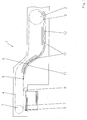
- Fig. 1 shows a schematic representation of a side view of a sheet delivery 1 with delivery extension.
- the front and rear chain guide wheels 2, 3 are shown, via which the closed gripper chain 4 with the grippers 5 is guided.
- the grippers 5 are used to convey the printing material, for example sheets 6 to the delivery stack 7.
- the suction roll 8 and the front sheet stops 9 are also shown.
- dryers 10 are arranged above the conveyor run of the delivery chain.
- the sheet guide device according to the invention which has the structure described below, is provided under the gripper chain 4 below the sheet conveying path.
- the sheet guiding device which extends over the width of the sheet conveying path, has a smooth sheet guide surface 11 on the side facing the sheet 6.
- a flat container 13 is provided for receiving the liquid release agent 10. This is connected via lines 16 to a storage tank 14 from which the container 13 is fed by means of a pump 15 with release agent 10.
- a device for processing the release agent (not shown in the drawing) is provided his.
- the sheet guide surface 11 forms the top of the container 13 and is of openings 12 perforated, which are arranged regularly. These openings 12 can in a first embodiment with a correspondingly small diameter as capillaries be so that the release agent 10 under the action of capillary pressure on the sheet guide surface 11 is promoted.
- the openings are enlarged executed.
- a pump 15 is provided to promote the release agent 10 an overpressure is generated in the container interior 13.
- Line path 16 can also be arranged a valve 19.
- the overpressure can also be adjusted by regulating the delivery rate of the pump 15.
- FIG 3 In a further embodiment, shown in Figure 3, are in the openings 12 of the sheet guide surface 11 stopper 17 made of elastic material. These have a continuous Opening, in each of which an absorbent wick 18 under the clamping action of the elastic Material is fixed. At the end of each plug facing the bend 6 a step is formed which in corresponding recesses in the sheet guide surface 11th is insertable.
- the sheet guide surface 11 can have a hydrophilic surface.
- This consists of inorganic nanocrystalline particles modified with additives or another suitable material.
- the modified inorganic nanosols consist of two components.
- the first component includes inorganic oxidic nanoparticles of elements from II. - V. main and sub-group of the periodic table or their mixtures. These are preferably nanoparticles consisting of SiO 2 , TiO 2 ; Al 2 O 3 or mixtures thereof in aqueous, alcoholic or mixed solvents.
- the second component consists of the coating material of admixable additives to achieve the hydrophilic behavior and increase the surface energy of the coating.
- the additives mentioned above can be used individually or in combination of two or more be used.
- the nanosol layer can be easily produced using the sol-gel method be generated.
- the function of the sheet guiding device is as follows: The sheets 6 are conveyed through the machine in the gripper closure, so that they reach the delivery stack 7 almost without contact.
- the subject matter of the invention becomes effective when the sheet 6 touches the sheet guide surface 11.
- release agent 10 is conveyed from the container 13 onto the sheet guide surface 11 and spreads to a release agent film. This forms an ink-repellent separating layer, so that a freshly printed surface does not smear when it contacts the sheet guide plate 11.
Landscapes
- Supply, Installation And Extraction Of Printed Sheets Or Plates (AREA)
- Feeding Of Articles By Means Other Than Belts Or Rollers (AREA)
Abstract
Description
Infolge seiner Abweichung von der vorgeschriebenen Greiferaufschlagbahn kann der Bogen, insbesondere wenn er im Schön- und Widerdruck bedruckt worden ist, an Maschinenteilen unterhalb des Bogenförderweges abschmieren. Gleiches trifft für die Bogenführungselemente zwischen den Druckwerken.
Einen Schutz für den bewegten Druckbogen, der die feststehende Leiteinrichtung berührt, gewährleistet die Trennmittelschicht nicht. Berührt der Bogen die Leiteinrichtung, schmiert der Bogen im Druckbild ab.
Das Aufbringen der Wasserschicht erweist sich infolge der benötigten Kühlung als energieintensiv.
Die Verteilung des auf die Bogenleitfläche geförderten Trennmittels ist von den Wechselwirkungen zwischen den Trennmittelmolekülen und den Molekülen der Oberfläche der Bogenleitfläche abhängig. Bei einer bevorzugten Ausführungsform ist die Bogenleitfläche deshalb mit einer hydrophilen Oberfläche versehen. Dadurch wird erreicht, dass sich eine Trennschicht konstanter Dicke ausbildet. Durch die Ausgestaltung der hydrophilen Oberfläche in Form einer Schicht von modifizierten anorganischen nanokristallinen Partikeln lässt sich die Hydrophilie der Oberfläche derart steigern, dass bereits aus geringen Trennmittelmengen ein geschlossener, die gesamte Bogenleitfläche überziehender Trennmittelfilm geringster Schichtdicke entsteht. Bereits ein wenige Moleküllagen dicker wässriger Trennmittelfilm zwischen der Bogenleiteinrichtung und der mit Farbe bedruckten Seite des Bogens reicht aus, um die Probleme des Farbabschmierens an Bogenleiteinrichtungen im Bogenausleger und im Druckwerk bei beidseitig bedruckten Bogen weitestgehend zu vermeiden.
Die Hydrophilie der Bogenleitfläche wirkt als zudem Transportmechanismus für auskondensiertes Wasser entlang der Bogenleitfläche. Dieser Effekt erweist sich als besonders vorteilhaft, wenn der Trennmittelfilm durch Kontakt mit einer Folge von Bögen partiell gestört wird. Infolge der starken Hydrophilie der Bogenleitfläche wird die Trennmittelschicht bis zum Eintreffen des jeweiligen Folgebogens wieder vollständig regeneriert.
In den dazugehörenden Zeichnungen zeigen
- Fig. 1:
- die schematische Darstellung einer Bogenleiteinrichtung in einem Bogenausleger mit Auslageverlängerung;
- Fig. 2:
- die Ausführung einer Bogenleiteinrichtung bei der die Förderung des Trennmittels durch Überdruck erfolgt;
- Fig. 3:
- die Ausführung einer Bogenleiteinrichtung bei der die Förderung des Trennmittels durch die Saugwirkung von Dochten erfolgt.
Unter der Greiferkette 4 unterhalb des Bogenförderweges ist die erfindungsgemäße Bogenleiteinrichtung vorgesehen, die den nachfolgend beschriebenen Aufbau aufweist.
Die zweite Komponente besteht aus dem Beschichtungsmaterial zumischbaren Additiven zur Erreichung des hydrophilen Verhaltens und Erhöhung der Oberflächenenergie der Beschichtung.
- Tensid-Verbindungen, bestehend aus langkettigen Alkyl- oder Fluoralkylresten mit mehr als 8 Kohlenstoffatomen und ein oder mehreren positiv oder negativ geladenen ionischen Endgruppen (z.B. 8% Cetyltrimethylammoniumbromid CTAB oder 2% Natriumdodecylsulfat oder 15% Perfluoralkylsulfonat FT2)
- Polysiloxan-Verbindungen mit hydrophilen Seiten- oder Endgruppen, vorzugsweise E-thylenoxid- oder Alkoholgruppen (z.B. 16% Polysiloxan NM4 oder 50% Polysiloxan A200)
- organische Polymere mit positiv oder negativ geladenen ionischen Seiten- oder Endgruppen (z.B. 2% Polystyrensulfonat 3000)
- wasserlösliche Mono-, Oligo- und Polysaccharid-Verbindungen und Derivate (z.B. 20% Sorbit)
- anorganische Iso- und Heteropolysäuren (z.B. 20% P2O5)
Die Bögen 6 werden im Greiferschluss durch die Maschine gefördert, so dass sie nahezu berührungslos bis zum Auslegerstapel 7 gelangen.
Der Erfindungsgegenstand wird wirksam bei Berührung des Bogens 6 mit der Bogenleitfläche 11.
Dazu wird aus dem Behälter 13 Trennmittel 10 auf die Bogenleitfläche 11 gefördert und spreitet zu einem Trennmittelfilm. Dieser bildet eine farbabstoßende Trennschicht, so dass eine frisch bedruckte Fläche bei Berührung mit dem Bogenleitblech 11 nicht abschmiert.
- 1
- Bogenausleger
- 2
- vorderes Kettenumlenkrad
- 3
- hinteres Kettenumlenkrad
- 4
- Greiferkette
- 5
- Greifer
- 6
- Bogen
- 7
- Auslegerstapel
- 8
- Saugwalze
- 9
- Bogenanschlag
- 10
- Trennmittel
- 11
- Bogenleitfläche
- 12
- Öffnungen
- 13
- Behälter
- 14
- Vorratstank
- 15
- Pumpe
- 16
- Leitungen
- 17
- Stopfen
- 18
- Dochte
- 19
- Ventil
Claims (14)
- Bogenleiteinrichtung in Bogenauslegern und/oder unter Bogenführungszylindern von Druckmaschinen, in denen eine bedruckte Fläche des von Greifern (5) geförderten Bogens (6) auf die Bogenleiteinrichtung zeigt, wobeidie Bogenleiteinrichtung aus einem Behälter (13) zur Aufnahme eines flüssigen Trennmittels (10) besteht,der Behälter (13) auf der dem Bogen (6) zugewandten Seite eine Bogenleitfläche (11) aufweist,in der Öffnungen (12) vorgesehen sind, durch die das Trennmittel (10) aus dem Inneren des Behälters (13) auf die Bogenleitfläche (11) förderbar ist.
- Bogenleiteinrichtung nach Anspruch 1, wobei die Bogenleitfläche (11) eine hydrophile Oberfläche aufweist.
- Bogenleiteinrichtung nach Anspruch 2, wobei als hydrophile Oberfläche eine Nanosolschicht aus mit Additiven modifizierten anorganischen nanokristallinen Partikeln vorgesehen ist.
- Bogenleiteinrichtung nach Anspruch 3, wobei die nanokristallinen Partikel aus Siliziumoxid, Titanoxid oder Aluminiumoxid oder aus Gemischen der genannten Oxide bestehen.
- Bogenleiteinrichtung nach Anspruch 3 oder 4, wobei als Additive Tensid-Verbindungen aus langkettigen Alkyl- oder Fluoralkylresten mit mehr als acht Kohlenstoffatomen und ein oder mehreren positiv oder negativ geladenen ionischen Endgruppen eingesetzt werden.
- Bogenleiteinrichtung nach Anspruch 3 oder 4, wobei als Additive Polysiloxan-Verbindungen mit hydrophilen Seiten- oder Endgruppen, vorzugsweise Ethylenoxidoder Alkoholgruppen eingesetzt werden.
- Bogenleiteinrichtung nach Anspruch 3 oder 4, wobei als Additive wasserlösliche Mono-, Oligo- und Polysaccharid-Verbindungen und Derivate eingesetzt werden.
- Bogenleiteinrichtung nach Anspruch 3 oder 4, wobei als Additive anorganische Iso- und Heteropolysäuren eingesetzt werden.
- Bogenleiteinrichtung nach einem der Ansprüche 1 bis 8, wobei die Öffnungen (12) so dimensioniert sind, dass die Förderung des Trennmittels (19) auf die Bogenleitfläche (11) unter Wirkung des Kapillardruck erfolgt.
- Bogenleiteinrichtung nach einem der Ansprüche 1 bis 8, wobei in den Öffnungen (12) die Förderung des Trennmittels (10) bewirkende Dochte (18) angeordnet sind.
- Bogenleiteinrichtung nach Anspruch 10, wobei die Öffnungen (12) in der Bogenleitfläche (11) mit Stopfen aus elastischem Material ausgekleidet sind, die eine Durchgangsöffnung aufweisen, in der die Dochte (18) fixiert sind.
- Bogenleiteinrichtung nach einem der Ansprüche 1 bis 8, wobei Mittel vorgesehen sind, mit denen im Behälter (13) ein Überdruck erzeugbar ist, der die Förderung des Trennmittels (10) auf die Bogenleitfläche (11) bewirkt.
- Bogenleiteinrichtung nach einem der vorhergehenden Ansprüche, wobei der Behälter (13) mit einer Einrichtung zur Aufbereitung des Trennmittels (10) verbunden ist.
- Bogenleiteinrichtung nach einem der vorhergehenden Ansprüche, wobei als Trennmittel (10) eine wässrige Lösung vorgesehen ist, welche die Oberflächenspannung erniedrigende Zusätze enthält.
Applications Claiming Priority (2)
| Application Number | Priority Date | Filing Date | Title |
|---|---|---|---|
| DE10217708 | 2002-04-20 | ||
| DE2002117708 DE10217708A1 (de) | 2002-04-20 | 2002-04-20 | Bogenleiteinrichtung |
Publications (3)
| Publication Number | Publication Date |
|---|---|
| EP1354703A2 true EP1354703A2 (de) | 2003-10-22 |
| EP1354703A3 EP1354703A3 (de) | 2004-10-27 |
| EP1354703B1 EP1354703B1 (de) | 2006-05-24 |
Family
ID=28458945
Family Applications (1)
| Application Number | Title | Priority Date | Filing Date |
|---|---|---|---|
| EP20030006277 Expired - Lifetime EP1354703B1 (de) | 2002-04-20 | 2003-03-21 | Bogenleiteinrichtung |
Country Status (2)
| Country | Link |
|---|---|
| EP (1) | EP1354703B1 (de) |
| DE (2) | DE10217708A1 (de) |
Citations (3)
| Publication number | Priority date | Publication date | Assignee | Title |
|---|---|---|---|---|
| DE2127021A1 (de) | 1970-07-23 | 1972-01-27 | VEB Polygraph Leipzig, Kombinat für polygraphische Maschinen und Ausrüstungen, χ 7050 Leipzig | Anordnung zur Regulierung der Feuchtigkeitsfilmdicke auf Zylindermantelflächen von Druckmaschinen |
| DE4341566A1 (de) | 1993-12-07 | 1995-06-08 | Heidelberger Druckmasch Ag | Einrichtung zum Oberflächenschutz frisch bedruckter Bogen |
| DE19716424A1 (de) | 1997-04-18 | 1998-11-05 | Kba Planeta Ag | Einrichtung zum Vermeiden des Ablegens von Farbe |
Family Cites Families (6)
| Publication number | Priority date | Publication date | Assignee | Title |
|---|---|---|---|---|
| DE263343C (de) * | ||||
| US1336995A (en) * | 1919-07-31 | 1920-04-13 | Allen B Beck | Device for preventing offset in printing-presses |
| US4312268A (en) * | 1979-12-10 | 1982-01-26 | The Standard Register Company | Apparatus and method for coating of inks applied at high speed |
| DE3422443C2 (de) * | 1984-06-16 | 1989-11-23 | Heidelberger Druckmaschinen Ag, 6900 Heidelberg | Folie für bogenführende Zylinder und Trommeln in Rotations-Offsetdruckmaschinen |
| DE3644446A1 (de) * | 1986-12-24 | 1988-07-07 | Roland Man Druckmasch | Vorrichtung zum verhindern des abhebens von bogen von einem zylinder einer druckmaschine |
| DE4200767A1 (de) * | 1991-11-21 | 1993-05-27 | Windmoeller & Hoelscher | Druckmaschine |
-
2002
- 2002-04-20 DE DE2002117708 patent/DE10217708A1/de not_active Withdrawn
-
2003
- 2003-03-21 EP EP20030006277 patent/EP1354703B1/de not_active Expired - Lifetime
- 2003-03-21 DE DE50303426T patent/DE50303426D1/de not_active Expired - Lifetime
Patent Citations (3)
| Publication number | Priority date | Publication date | Assignee | Title |
|---|---|---|---|---|
| DE2127021A1 (de) | 1970-07-23 | 1972-01-27 | VEB Polygraph Leipzig, Kombinat für polygraphische Maschinen und Ausrüstungen, χ 7050 Leipzig | Anordnung zur Regulierung der Feuchtigkeitsfilmdicke auf Zylindermantelflächen von Druckmaschinen |
| DE4341566A1 (de) | 1993-12-07 | 1995-06-08 | Heidelberger Druckmasch Ag | Einrichtung zum Oberflächenschutz frisch bedruckter Bogen |
| DE19716424A1 (de) | 1997-04-18 | 1998-11-05 | Kba Planeta Ag | Einrichtung zum Vermeiden des Ablegens von Farbe |
Also Published As
| Publication number | Publication date |
|---|---|
| EP1354703A3 (de) | 2004-10-27 |
| DE10217708A1 (de) | 2003-11-06 |
| EP1354703B1 (de) | 2006-05-24 |
| DE50303426D1 (de) | 2006-06-29 |
Similar Documents
| Publication | Publication Date | Title |
|---|---|---|
| EP0074045A1 (de) | Vorrichtung zum Aufbringen von Puderteilchen | |
| EP0978467B1 (de) | Ausleger für eine Druckmaschine | |
| DE102008061216A1 (de) | Lackiereinrichtung für UV-Lack | |
| EP0703072A1 (de) | Bogenüberführtrommel | |
| DE9416106U1 (de) | Bogenleitblech für eine Wendeeinrichtung | |
| DE2648986B1 (de) | Bogenglaetter an Druckmaschinen | |
| DE10102221A1 (de) | Vorrichtung zum Verlangsamen von Signaturen | |
| DE19914177A1 (de) | Ausleger einer Bogen verarbeitenden Druckmaschine | |
| DE3114581C2 (de) | Fördervorrichtung für eine Bogen-Rotationsdruckmaschine | |
| DE19814006C1 (de) | Verfahren und Einrichtung zur Bogenführung an einer Leitrakel in Druckmaschinen | |
| DE10056018B4 (de) | Einrichtung zur Unterstützung der Bogenführung und Bogenablage | |
| EP1354703B1 (de) | Bogenleiteinrichtung | |
| DE4344039C2 (de) | Bogenleiteinrichtung in umstellbaren Druckmaschinen | |
| EP0922577A1 (de) | Bogenführungseinrichtung in einer Druckmaschine | |
| DE19713361B4 (de) | Verfahren und Vorrichtung zum abschmierfreien Führen eines bedruckten Bogens auf einem bogenführenden Zylinder einer Druckmaschine, insbesondere auf einer Wendetrommel einer Bogenrotations-Offsetdruckmaschine, im Schöndruckbetrieb | |
| EP1354702B1 (de) | Bogenleiteinrichtung | |
| DE3308844A1 (de) | Greiferwagen in auslegern von bogendruckmaschinen | |
| DE10304617B4 (de) | Bogenförderer für eine Bogen verarbeitende Maschine | |
| DE19513427C2 (de) | Bogenführungseinrichtung an Bogenführungszylindern in Druckmaschinen | |
| DE102006048081B4 (de) | Greifersystemkörper für ein endlos umlaufendes Fördersystem in einer Verarbeitungsmaschine | |
| DE679390C (de) | Vorrichtung zum Foerdern von Bogen in Falzmaschinen | |
| DE10144159A1 (de) | Bogenleiteinrichtung | |
| DE3509696A1 (de) | Einrichtung in bogenauslegern | |
| DD225411B1 (de) | Einrichtung zur einwirkung auf den bogen in bogenauslegern | |
| DE3628788A1 (de) | Blaseinrichtung in druckmaschinen |
Legal Events
| Date | Code | Title | Description |
|---|---|---|---|
| PUAI | Public reference made under article 153(3) epc to a published international application that has entered the european phase |
Free format text: ORIGINAL CODE: 0009012 |
|
| AK | Designated contracting states |
Kind code of ref document: A2 Designated state(s): AT BE BG CH CY CZ DE DK EE ES FI FR GB GR HU IE IT LI LU MC NL PT RO SE SI SK TR |
|
| AX | Request for extension of the european patent |
Extension state: AL LT LV MK |
|
| PUAL | Search report despatched |
Free format text: ORIGINAL CODE: 0009013 |
|
| AK | Designated contracting states |
Kind code of ref document: A3 Designated state(s): AT BE BG CH CY CZ DE DK EE ES FI FR GB GR HU IE IT LI LU MC NL PT RO SE SI SK TR |
|
| AX | Request for extension of the european patent |
Extension state: AL LT LV MK |
|
| RIC1 | Information provided on ipc code assigned before grant |
Ipc: 7B 41F 21/00 A Ipc: 7B 41F 22/00 B Ipc: 7B 65H 29/52 B |
|
| 17P | Request for examination filed |
Effective date: 20041011 |
|
| 17Q | First examination report despatched |
Effective date: 20050301 |
|
| AKX | Designation fees paid |
Designated state(s): DE FR GB IT |
|
| GRAP | Despatch of communication of intention to grant a patent |
Free format text: ORIGINAL CODE: EPIDOSNIGR1 |
|
| GRAS | Grant fee paid |
Free format text: ORIGINAL CODE: EPIDOSNIGR3 |
|
| GRAA | (expected) grant |
Free format text: ORIGINAL CODE: 0009210 |
|
| AK | Designated contracting states |
Kind code of ref document: B1 Designated state(s): DE FR GB IT |
|
| PG25 | Lapsed in a contracting state [announced via postgrant information from national office to epo] |
Ref country code: IT Free format text: LAPSE BECAUSE OF FAILURE TO SUBMIT A TRANSLATION OF THE DESCRIPTION OR TO PAY THE FEE WITHIN THE PRESCRIBED TIME-LIMIT;WARNING: LAPSES OF ITALIAN PATENTS WITH EFFECTIVE DATE BEFORE 2007 MAY HAVE OCCURRED AT ANY TIME BEFORE 2007. THE CORRECT EFFECTIVE DATE MAY BE DIFFERENT FROM THE ONE RECORDED. Effective date: 20060524 |
|
| REG | Reference to a national code |
Ref country code: GB Ref legal event code: FG4D Free format text: NOT ENGLISH |
|
| REF | Corresponds to: |
Ref document number: 50303426 Country of ref document: DE Date of ref document: 20060629 Kind code of ref document: P |
|
| GBT | Gb: translation of ep patent filed (gb section 77(6)(a)/1977) |
Effective date: 20060920 |
|
| ET | Fr: translation filed | ||
| PLBE | No opposition filed within time limit |
Free format text: ORIGINAL CODE: 0009261 |
|
| STAA | Information on the status of an ep patent application or granted ep patent |
Free format text: STATUS: NO OPPOSITION FILED WITHIN TIME LIMIT |
|
| 26N | No opposition filed |
Effective date: 20070227 |
|
| PGFP | Annual fee paid to national office [announced via postgrant information from national office to epo] |
Ref country code: IT Payment date: 20120328 Year of fee payment: 10 |
|
| PGFP | Annual fee paid to national office [announced via postgrant information from national office to epo] |
Ref country code: GB Payment date: 20130321 Year of fee payment: 11 Ref country code: FR Payment date: 20130408 Year of fee payment: 11 |
|
| PGFP | Annual fee paid to national office [announced via postgrant information from national office to epo] |
Ref country code: DE Payment date: 20130330 Year of fee payment: 11 |
|
| REG | Reference to a national code |
Ref country code: DE Ref legal event code: R119 Ref document number: 50303426 Country of ref document: DE |
|
| GBPC | Gb: european patent ceased through non-payment of renewal fee |
Effective date: 20140321 |
|
| REG | Reference to a national code |
Ref country code: FR Ref legal event code: ST Effective date: 20141128 |
|
| REG | Reference to a national code |
Ref country code: DE Ref legal event code: R119 Ref document number: 50303426 Country of ref document: DE Effective date: 20141001 |
|
| PG25 | Lapsed in a contracting state [announced via postgrant information from national office to epo] |
Ref country code: FR Free format text: LAPSE BECAUSE OF NON-PAYMENT OF DUE FEES Effective date: 20140331 Ref country code: DE Free format text: LAPSE BECAUSE OF NON-PAYMENT OF DUE FEES Effective date: 20141001 Ref country code: GB Free format text: LAPSE BECAUSE OF NON-PAYMENT OF DUE FEES Effective date: 20140321 |
|
| PG25 | Lapsed in a contracting state [announced via postgrant information from national office to epo] |
Ref country code: IT Free format text: LAPSE BECAUSE OF NON-PAYMENT OF DUE FEES Effective date: 20140321 |