EP1354652B1 - Verteilervorrichtung zur Verwendung beim Metallgiessen - Google Patents
Verteilervorrichtung zur Verwendung beim Metallgiessen Download PDFInfo
- Publication number
- EP1354652B1 EP1354652B1 EP03013924A EP03013924A EP1354652B1 EP 1354652 B1 EP1354652 B1 EP 1354652B1 EP 03013924 A EP03013924 A EP 03013924A EP 03013924 A EP03013924 A EP 03013924A EP 1354652 B1 EP1354652 B1 EP 1354652B1
- Authority
- EP
- European Patent Office
- Prior art keywords
- distributor device
- distributor
- mould
- aluminium
- outlet opening
- Prior art date
- Legal status (The legal status is an assumption and is not a legal conclusion. Google has not performed a legal analysis and makes no representation as to the accuracy of the status listed.)
- Expired - Lifetime
Links
Images


Classifications
-
- B—PERFORMING OPERATIONS; TRANSPORTING
- B22—CASTING; POWDER METALLURGY
- B22D—CASTING OF METALS; CASTING OF OTHER SUBSTANCES BY THE SAME PROCESSES OR DEVICES
- B22D41/00—Casting melt-holding vessels, e.g. ladles, tundishes, cups or the like
- B22D41/003—Casting melt-holding vessels, e.g. ladles, tundishes, cups or the like with impact pads
-
- B—PERFORMING OPERATIONS; TRANSPORTING
- B22—CASTING; POWDER METALLURGY
- B22C—FOUNDRY MOULDING
- B22C9/00—Moulds or cores; Moulding processes
- B22C9/08—Features with respect to supply of molten metal, e.g. ingates, circular gates, skim gates
- B22C9/082—Sprues, pouring cups
-
- B—PERFORMING OPERATIONS; TRANSPORTING
- B22—CASTING; POWDER METALLURGY
- B22D—CASTING OF METALS; CASTING OF OTHER SUBSTANCES BY THE SAME PROCESSES OR DEVICES
- B22D11/00—Continuous casting of metals, i.e. casting in indefinite lengths
- B22D11/10—Supplying or treating molten metal
- B22D11/103—Distributing the molten metal, e.g. using runners, floats, distributors
-
- B—PERFORMING OPERATIONS; TRANSPORTING
- B22—CASTING; POWDER METALLURGY
- B22D—CASTING OF METALS; CASTING OF OTHER SUBSTANCES BY THE SAME PROCESSES OR DEVICES
- B22D11/00—Continuous casting of metals, i.e. casting in indefinite lengths
- B22D11/10—Supplying or treating molten metal
- B22D11/11—Treating the molten metal
- B22D11/116—Refining the metal
- B22D11/119—Refining the metal by filtering
-
- B—PERFORMING OPERATIONS; TRANSPORTING
- B22—CASTING; POWDER METALLURGY
- B22D—CASTING OF METALS; CASTING OF OTHER SUBSTANCES BY THE SAME PROCESSES OR DEVICES
- B22D35/00—Equipment for conveying molten metal into beds or moulds
- B22D35/04—Equipment for conveying molten metal into beds or moulds into moulds, e.g. base plates, runners
-
- B—PERFORMING OPERATIONS; TRANSPORTING
- B22—CASTING; POWDER METALLURGY
- B22D—CASTING OF METALS; CASTING OF OTHER SUBSTANCES BY THE SAME PROCESSES OR DEVICES
- B22D41/00—Casting melt-holding vessels, e.g. ladles, tundishes, cups or the like
- B22D41/50—Pouring-nozzles
-
- B—PERFORMING OPERATIONS; TRANSPORTING
- B22—CASTING; POWDER METALLURGY
- B22D—CASTING OF METALS; CASTING OF OTHER SUBSTANCES BY THE SAME PROCESSES OR DEVICES
- B22D7/00—Casting ingots, e.g. from ferrous metals
- B22D7/12—Appurtenances, e.g. for sintering, for preventing splashing
-
- C—CHEMISTRY; METALLURGY
- C22—METALLURGY; FERROUS OR NON-FERROUS ALLOYS; TREATMENT OF ALLOYS OR NON-FERROUS METALS
- C22B—PRODUCTION AND REFINING OF METALS; PRETREATMENT OF RAW MATERIALS
- C22B21/00—Obtaining aluminium
- C22B21/0084—Obtaining aluminium melting and handling molten aluminium
Definitions
- the invention relates to a distributor device for use in an aluminium casting operation.
- the molten aluminium is cast into ingots or billets that are subsequently used in processes for manufacturing aluminium products, for example aluminium foil.
- the molten aluminium is transferred from a holding furnace into a water-cooled mould above a casting pit, where it solidifies to form an aluminium ingot.
- the molten aluminium is usually poured into the mould through a distributor device.
- a distributor device Conventionally, this consists of a flexible bag of coated woven glass fibres, known as a "combo bag", having an outer shell of solid woven fabric with normally two large openings through which the molten aluminium flows, and an inner liner of open-weave fabric.
- the molten aluminium flows through the small pores of the open-weave liner, then through the openings in the outer shell, which helps to prevent turbulence in the flow of aluminium.
- fibres can occasionally come loose from the fabric of the distributor and become entrained in the molten aluminium, thereby introducing impurities into the aluminium ingot and potentially causing considerable difficulties in subsequent manufacturing processes.
- Another distributor device described in US 5207974 has a "bag-in-bag” design, comprising an inner bag of impermeable fabric and an outer bag having outlet openings. The device is suspended above the mould and liquid metal is poured into the inner bag. When the metal reached the top of the inner bag, it overflows into the outer bag, then flows through the openings into the mould.
- the bag is flexible and is susceptible to the disadvantages mentioned above.
- US 5871660 describes two different distributor devices.
- One of these is a flexible bag type, which is susceptible to the disadvantages mentioned above.
- the other device comprises a rigid nozzle having four outlet openings that are angled to direct the molten metal towards the sides of the mould.
- the nozzle is geometrically complex and is difficult and expensive to produce.
- a distributor device for use in an aluminium casting operation to direct the flow of molten aluminium into a mould
- the distributor device including a rigid, substantially bowl-shaped receptacle of a refractory material having a base member and a peripheral wall that extends upwards from the base, said receptacle having an inlet opening towards the upper end thereof and at least one outlet opening towards the base thereof, the device being constructed and arranged such that, in use, molten aluminium poured into the distributor device through the inlet opening is redirected by the distributor device and flows outwards into the mould through the at least one outlet opening.
- the distributor device includes a porous element constructed and arranged such that, in use, molten aluminium poured into the distributor device flows through said porous element.
- the porous element helps to reduce turbulence. It also acts as a filter device that traps inclusions and any large particles that may be washed into the distributor.
- the porous element includes a substantially bowl-shaped mesh of woven material that fits into and is supported by the receptacle, the arrangement being such that molten aluminium poured into the distributor device through the inlet opening flows through the mesh of woven material before exiting through the at least one outlet opening.
- the porous element includes a mesh of coated glass fibres.
- the distributor device serves to direct the metal flow during casting.
- One of the advantages of using a rigid material is that it allows far more complex geometries to be made than can be achieved with conventional non-rigid systems, and allows those geometries to be reproduced consistently. This allows greater control and optimisation of the flow patterns emerging from the distributor, as well as opening up new ways of predicting the flow patterns (since 3-D fluid flow computer models work better with rigid structures).
- the device is not wetted by liquid aluminium and so is easy to clean. It may be slightly more expensive to manufacture than a disposable combo bag, but it can be re-used many times, thereby reducing wastage and providing a significant overall saving in costs. Also, the risk of loose fibres being trapped within the aluminium is avoided.
- Any refractory material that is suitable for prolonged contact with molten aluminium may be used. These include fused silica, alumina, mullite, silicon carbide, silicon nitride, silicon aluminium oxy-nitride, zircon, magnesia, zirconia, graphite, wollastonite, calcium silicate, boron nitride (solid BN), aluminium titanate, aluminium nitride (AIN) and titanium diboride (TiB2) etc., or any composite of these materials. Alternatively, a suitable metal may be used, for example grey cast iron or titanium.
- At least one outlet opening is provided in the peripheral wall, the device being constructed and arranged such that, in use, molten aluminium flows substantially horizontally outwards through said at least one outlet opening. This produces a good, non-turbulent flow pattern.
- At least one outlet opening may be provided in the lower part of the peripheral wall, adjacent the base member, and the base member may be inclined towards the or each outlet opening. This provides good drainage.
- the peripheral wall includes two side wall members and two end wall members. At least one outlet opening may be provided in each end wall member.
- the separation of the side wall members increases towards the ends thereof.
- the side wall members are curved. These features also promote a good, non-turbulent flow pattern.
- the base member may include a raised flow deflector, to redirect the flow of aluminium as it is poured into the distributor device.
- the peripheral wall is inclined outwards.
- the distributor device may include a heating element for pre-heating the device, to prevent the metal freezing when pouring begins.
- the distributor device may include a support structure, which may be designed to allow the device to be removed and replaced easily.
- the porous element includes a support frame that, in use, engages and is supported by the receptacle.
- a distributor device for use in aluminium casting, the distributor device including a rigid, substantially bowl-shaped receptacle of a refractory material having an inlet opening at the top and at least one outlet opening towards the base thereof, and an inner liner including a substantially bowl-shaped mesh of woven material that fits into and is supported by said rigid receptacle, the arrangement being such that molten aluminium poured into the distributor device through the inlet opening flows through the mesh of woven material before exiting through the at least one outlet opening.
- the rigid receptacle supports the inner liner during the casting process and directs the flow of molten aluminium, while the inner liner helps to prevent turbulence.
- the receptacle can be used several times. It is therefore only necessary to replace the relatively inexpensive inner lining for each casting process, thereby reducing the cost of the process.
- the rigid receptacle includes a ceramic shell.
- the ceramic shell can withstand the extremely high temperature of the molten aluminium and provide a rigid support for the inner liner. It is also relatively inexpensive. Further, because a fabric outer support is not required, the risk of loose fibres becoming entrained in the molten aluminium is significantly reduced.
- the device includes means for supporting the rigid receptacle, which preferably allows the receptacle to be replaced relatively quickly and easily, when necessary.
- the base of the rigid receptacle has an upper surface that is convex, to ensure good drainage of the device at the end of the casting process.
- the rigid receptacle includes at least one heating element. This allows the receptacle to be pre-heated in situ prior to pouring the molten aluminium.
- the inner liner includes a mesh of woven material, preferably of coated glass. This material can withstand the very high temperature of the molten aluminium.
- the inner liner includes a support frame that, in use, engages and is supported by the rigid receptacle. This retains the inner liner in position and prevents it floating on the molten aluminium.
- an aluminium casting installation including a mould, a delivery device for delivering molten aluminium into the mould and a distributor device according to any one of the accompanying claims, the distributor device being mounted below the delivery device and above the mould, the installation being constructed and arranged such that, in use, molten aluminium is poured from the delivery device into the mould through the distributor device.
- the distributor device is positioned so that, during pouring, it is partially immersed in the liquid metal in the mould with the at least one outlet opening below the surface of the liquid metal.
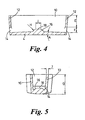
- a distributor device 2 according to a first embodiment of the invention is shown in Figs. 1 to 5 of the drawings.
- the device is intended for use in an aluminium casting operation to direct the flow of molten aluminium into a mould, the device being located in use just above the mould, so that during pouring it is partially submerged below the surface of the molten metal in the mould.
- the distributor device 2 includes a rigid, substantially bowl-shaped receptacle of a refractory material having a base member 4 and a peripheral wall 6 that extends upwards from the base and is inclined slightly outwards, forming an inlet opening 8 towards the upper end of the device.
- the peripheral wall 6 is four-sided and includes two side wall members 10 and two end wall members 12.
- the side wall members 10 are curved inwards lending the device a bi-concave shape, the separation of the side wall members increasing towards the ends of those walls.
- An outlet opening 14 is provided in the lower part of each end wall member 12, the lower edge of each opening being flush with the upper surface of the base member 4.
- Each opening 14 extends substantially horizontally through the walls and is constructed and arranged such that, in use, molten aluminium flows substantially horizontally outwards through it.
- the base member 4 is inclined towards the outlet openings 14 and includes a raised flow deflector element 16 that deflects the flow of molten aluminium poured into the device and directs it towards the outlet openings 14.
- the flow deflector element 16 is substantially hemi-spherical but has a flat top surface 18.
- the distributor device 2 may be made from any refractory material that is suitable for prolonged contact with molten aluminium. These include fused silica, alumina, mullite, silicon carbide, silicon nitride, silicon aluminium oxy-nitride, zircon, magnesia, zirconia, graphite, wollastonite, calcium silicate, boron nitride (solid BN), aluminium titanate, aluminium nitride (AIN) and titanium diboride (TiB2) etc. Furthermore, the device may be made from a composite material formed from a combination of the materials listed above, or it may be formed by impregnating a combination of these materials into a fibrous mat substrate. Alternatively, the distributor device may be made of a suitable metal, for example grey cast iron or titanium.
- the distributor device 2 is mounted within the upper part of a water-cooled mould 20, as shown in Fig. 6, with the outlet openings 14 just below the surface 22 of the molten aluminium in the mould.
- the distributor device is supported by two horizontal support rods 24 that pass through support loops 26 attached to the sides of the distributor device.
- Molten aluminium is poured from a holding furnace into a launder trough 28, from which it flows through a spout 30 into the open top of the distributor device 2.
- the liquid aluminium is deflected outwards by the deflector element 16 and is directed towards the end walls 12 by the curved side walls 10.
- the aluminium then flows outwards through the outlet openings 14 into the mould 20, where it solidifies to form an aluminium ingot.
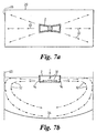
- the flow of aluminium through the distributor device (which is illustrated by arrows 32) is determined by the shape of the device and the geometry of its outlets, which are designed to produce a smooth, controlled flow pattern of metal in the mould, with a predictable heat distribution.
- the flow pattern is illustrated in Figures 7a and 7b.
- the distributor device 2 directs the liquid metal towards the short sides 33 of the mould 20, and produces a diverging flow pattern with metal flowing towards the corners as well as the middle of those sides.
- the flow of metal from the distributor device is substantially horizontal initially, as shown in side section in Fig. 7b, and then turns downwards and inwards as it reaches the sides 33 of the mould, producing a heart-shaped pattern above the metal solidification front 34.
- This pattern is generally considered to be ideal, and results in a very high quality ingot or billet.
- the device provides numerous advantages when used in the aluminium casting process. It is not wetted by liquid aluminium and so is easy to clean
- the device is re-useable, reducing wastage. It is inexpensive to manufacture, reducing costs. It has a sloped base so that metal runs out at the end of the cast and it drains easily.
- the flow deflector reduces or eliminates turbulence at the point of the direction change between spout and distributor.
- the rigid receptacle walls are curved to generate the desired metal flow pattern. With an appropriate mounting system, the device can be replaced quickly and easily when necessary, allowing consistent placement and thus reliable metal distribution.
- the device may include a mounting system for mounting it within the mould, for example by clamping or fixing a metal bracket to the top, sides, end or base of the device, or by integrating a suitable bracket into the device.
- the device may include a porous element for reducing turbulence further and trapping surface based oxide inclusions generated by turbulence in the metal or any large particles that may be washed into the distributor.
- This element may be formed from any suitable porous material. It can be made, for example, by sewing coated woven glass fibre cloth, thermally forming a resin coated woven glass fibre cloth, by incorporating a steel wire into the woven glass fibre cloth, by producing a ceramic replica of a reticulated polyurethane foam, etc.
- the device may include a heating element for heating the device in situ prior to use, to prevent the metal freezing when it first comes into contact with the device.
- a heating element for heating the device in situ prior to use, to prevent the metal freezing when it first comes into contact with the device.
- electrical heating elements can be incorporated into the walls and base of the device.
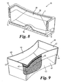
- FIG. 8 A second form of the distributor device is shown in Figs. 8 and 9.
- This device 36 includes a rigid, bowl-shaped receptacle 2 and a woven fabric inner liner 38 that forms an inner part of the distributor device and fits inside the receptacle 2.
- the receptacle 2 is substantially identical to the first distributor device described above, and will not be further described.
- the same reference numbers have been used to refer to similar parts.
- the inner liner 38 is made from a coated open weave fabric of glass fibres.
- the coating can be either organic or inorganic.
- An organic coating may for example be a derivative of polyvinyl alcohol, whereas an inorganic coating can be a colloidal silica with a small quantity of starch to add stiffness.
- the liner 38 is substantially bowl-shaped and designed to fit into the rigid receptacle 2. As shown in Figure 9, it has a peripheral wall 40 with curved sides 41 and flat ends 42, and a substantially flat base 43. The upper part of the peripheral wall 40 is reinforced with a second layer 44 of woven glass fabric, which encapsulates a wire frame 45.
- the frame 45 is relatively springy, and provides additional stiffness to support the liner 38 in the outer receptacle 2.
- the inner liner 38 is placed in the outer ceramic receptacle 2.
- the frame 45 supports the liner against the walls 10,12 of the receptacle 2, and the liner adopts the internal shape of the receptacle, moulding itself over the deflector element 16, as shown in Figure 8.
- the mesh extends over the outlet openings 14, so that liquid metal flowing through the distributor passes through the mesh.
- the distributor device is suspended above the casting pit, substantially as shown in Fig. 6. As molten aluminium is poured into the distributor, it flows through the pores in the fabric inner liner 38, and out through the openings 14 in the receptacle 2.
- the rigid receptacle 2 directs the flow of molten aluminium, controlling the distribution and temperature profile of the metal in the mould, while the inner liner 38 reduces turbulence and traps surface based oxide inclusions and any large particles that may be washed into the distributor.
- the inner fabric liner 38 can be removed and discarded, leaving the ceramic receptacle 2 in place.
- the receptacle 2 may be used many times before it has to be replaced. It is not therefore necessary to replace the entire distributor after every casting operation, thereby simplifying the manufacturing process and reducing cost and waste.
- the rigid receptacle 2 may include electric heating elements (not shown), allowing it to be pre-heated in situ to the temperature of the molten aluminium prior to the casting process.
- the distributor need not necessarily have exactly the shape shown in the drawings but may be any shape, according to the dimensions and shape of the casting mould and the desired flow pattern. Additional windows and drain holes may also be provided, if required.
Landscapes
- Engineering & Computer Science (AREA)
- Mechanical Engineering (AREA)
- Chemical & Material Sciences (AREA)
- Manufacturing & Machinery (AREA)
- Materials Engineering (AREA)
- Metallurgy (AREA)
- Organic Chemistry (AREA)
- Continuous Casting (AREA)
- Casting Support Devices, Ladles, And Melt Control Thereby (AREA)
- Manufacture Of Alloys Or Alloy Compounds (AREA)
- Valve-Gear Or Valve Arrangements (AREA)
- Molds, Cores, And Manufacturing Methods Thereof (AREA)
- Ignition Installations For Internal Combustion Engines (AREA)
- Injection Moulding Of Plastics Or The Like (AREA)
- Eye Examination Apparatus (AREA)
- Spinning Methods And Devices For Manufacturing Artificial Fibers (AREA)
- Casting Or Compression Moulding Of Plastics Or The Like (AREA)
- Devices For Post-Treatments, Processing, Supply, Discharge, And Other Processes (AREA)
Claims (16)
- Verteilervorrichtung zur Verwendung beim Aluminiumgießen um den Fluß des geschmolzenen Aluminiums in eine Gießform zu leiten, wobei die Verteilervorrichtung ein steifes, im wesentlichen schalenförmiges Behältnis (2) aus feuerfestem Material mit einem Bodenteil (4) und einer umgebenden Wand (6), die sich von dem Bodenteil nach oben erstreckt, aufweist, wobei das Behältnis eine Einlaßöffnung (8) in Richtung ihres oberen Endes, ein poröses Element (38) und zumindest eine Auslaßöffnung (14) im Bereich ihres Bodens aufweist, wobei die Vorrichtung derart konstruiert und angeordnet ist, daß das im Betrieb durch die Einlaßöffnung (8) in die Verteilervorrichtung fließende geschmolzene Aluminium durch die Verteilervorrichtung umgeleitet wird und durch das genannte poröse Element (38) auswärts durch die zumindest eine Auslaßöffnung (14) in die Gießform fließt, dadurch gekennzeichnet, daß das poröse Element (38) ein im wesentlichen schalenförmiges Gitter aus gewebtem Material ist, das in das Behältnis (2) paßt und von dem Behältnis (2) unterstützt wird.
- Verteilervorrichtung nach Anspruch 1, wobei mindestens eine Auslaßöffnung (14) in der umgebenden Wand (6) angeordnet ist, wobei die Vorrichtung derart ausgelegt und angeordnet ist, daß das geschmolzene Aluminium im Betrieb im wesentlichen horizontal durch die wenigstens eine Auslaßöffnung (14) auswärts fließt.
- Verteilervorrichtung nach Anspruch 2, wobei zumindest eine Auslaßöffnung (14) im unteren Teil der umgebenden Wand (6) dem Bodenteil (4) benachbart vorgesehen ist.
- Verteilervorrichtung nach Anspruch (3), wobei die obere Oberfläche des Bodenteils (4) in Richtung auf die oder jede Auslaßöffnung (14) geneigt ist.
- Verteilervorrichtung nach einem der voranstehenden Ansprüche, wobei die umgebende Wand (6) zwei Seitenwandteile (10) und zwei Endwandteile (12) aufweist.
- Verteilervorrichtung nach Anspruch 5, wobei zumindest eine Auslaßöffnung (14) in jedem Endwandteil (12) vorgesehen ist.
- Verteilervorrichtung nach Anspruch 5 oder 6, wobei der Abstand zwischen den Seitenwandteilen (10) in Richtung auf ihre Enden zunimmt.
- Verteilervorrichtung nach Anspruch 7, wobei die Seitenwandteile (10) gewölbt sind.
- Verteilervorrichtung nach einem der voranstehenden Ansprüche, wobei das Bodenteil (4) einen erhöhten Flußablenker (16) enthält.
- Verteilervorrichtung nach einem der voranstehenden Ansprüche, wobei die Umgebungswand (6) auswärts geneigt ist.
- Verteilervorrichtung nach einem der voranstehenden Ansprüche, die ein Heizelement zum Vorheizen der Vorrichtung aufweist.
- Verteilervorrichtung nach einem der voranstehenden Ansprüche, die eine Unterstützungsstruktur (24,26) enthält.
- Verteilervorrichtung nach einem der voranstehenden Ansprüche, bei der das poröse Element (38) ein Gitter aus beschichteten Glasfasern enthält.
- Verteilervorrichtung nach einem der voranstehenden Ansprüche 12 und 14, bei der das poröse Element (38) einen Unterstützungsrahmen (45) enthält, der im Betrieb das Behältnis (2) berührt und von diesem unterstützt wird.
- Eine Aluminiumgießeinrichtung mit einer Gießform (20), einer Abgabevorrichtung (28,30) zur Abgabe flüssigen Aluminiums in die Gießform und einer Verteilervorrichtung (2) nach einem der voranstehenden Ansprüche, wobei die Verteilervorrichtung (2) unter der Abgabevorrichtung (28,30) und über der Gießform (20) befestigt ist, wobei die Einrichtung derart gebaut und angeordnet ist, daß das geschmolzene Aluminium im Betrieb von der Abgabevorrichtung durch die Verteilervorrichtung in die Gießform gegossen wird.
- Aluminiumgießeinrichtung nach Anspruch 15, wobei die Verteilereinrichtung (2) derart positioniert ist, daß sie während des Gießens teilweise in das flüssige Metall in der Gießform (20) eingetaucht ist mit der zumindest einen Auslaßöffnung (14) unterhalb der Oberfläche (22) des flüssigen Metalls.
Applications Claiming Priority (3)
| Application Number | Priority Date | Filing Date | Title |
|---|---|---|---|
| GB9918350A GB2352992B (en) | 1999-08-05 | 1999-08-05 | Distributor device |
| GB9918350 | 1999-08-05 | ||
| EP00953275A EP1198314B1 (de) | 1999-08-05 | 2000-08-04 | Verteilervorrichtung zur verwendung beim metallgiessen |
Related Parent Applications (1)
| Application Number | Title | Priority Date | Filing Date |
|---|---|---|---|
| EP00953275A Division EP1198314B1 (de) | 1999-08-05 | 2000-08-04 | Verteilervorrichtung zur verwendung beim metallgiessen |
Publications (3)
| Publication Number | Publication Date |
|---|---|
| EP1354652A2 EP1354652A2 (de) | 2003-10-22 |
| EP1354652A3 EP1354652A3 (de) | 2004-01-14 |
| EP1354652B1 true EP1354652B1 (de) | 2004-12-08 |
Family
ID=10858545
Family Applications (4)
| Application Number | Title | Priority Date | Filing Date |
|---|---|---|---|
| EP04020511A Expired - Lifetime EP1504834B1 (de) | 1999-08-05 | 2000-08-04 | Verteilervorrichtung zur Verwendung beim Metallgiessen |
| EP05013742A Expired - Lifetime EP1591177B1 (de) | 1999-08-05 | 2000-08-04 | Verteiler |
| EP00953275A Expired - Lifetime EP1198314B1 (de) | 1999-08-05 | 2000-08-04 | Verteilervorrichtung zur verwendung beim metallgiessen |
| EP03013924A Expired - Lifetime EP1354652B1 (de) | 1999-08-05 | 2000-08-04 | Verteilervorrichtung zur Verwendung beim Metallgiessen |
Family Applications Before (3)
| Application Number | Title | Priority Date | Filing Date |
|---|---|---|---|
| EP04020511A Expired - Lifetime EP1504834B1 (de) | 1999-08-05 | 2000-08-04 | Verteilervorrichtung zur Verwendung beim Metallgiessen |
| EP05013742A Expired - Lifetime EP1591177B1 (de) | 1999-08-05 | 2000-08-04 | Verteiler |
| EP00953275A Expired - Lifetime EP1198314B1 (de) | 1999-08-05 | 2000-08-04 | Verteilervorrichtung zur verwendung beim metallgiessen |
Country Status (15)
| Country | Link |
|---|---|
| US (2) | US7036555B1 (de) |
| EP (4) | EP1504834B1 (de) |
| JP (1) | JP3826229B2 (de) |
| AT (4) | ATE284287T1 (de) |
| AU (1) | AU757704B2 (de) |
| BR (1) | BR0013027A (de) |
| CA (4) | CA2479558C (de) |
| DE (4) | DE60023572T2 (de) |
| DK (4) | DK1198314T3 (de) |
| GB (1) | GB2352992B (de) |
| IS (1) | IS6243A (de) |
| NO (1) | NO20020484L (de) |
| RU (1) | RU2220817C2 (de) |
| WO (1) | WO2001010584A1 (de) |
| ZA (1) | ZA200200255B (de) |
Families Citing this family (49)
| Publication number | Priority date | Publication date | Assignee | Title |
|---|---|---|---|---|
| US7470392B2 (en) | 2003-07-14 | 2008-12-30 | Cooper Paul V | Molten metal pump components |
| US20050013715A1 (en) | 2003-07-14 | 2005-01-20 | Cooper Paul V. | System for releasing gas into molten metal |
| US20070253807A1 (en) | 2006-04-28 | 2007-11-01 | Cooper Paul V | Gas-transfer foot |
| US7731891B2 (en) | 2002-07-12 | 2010-06-08 | Cooper Paul V | Couplings for molten metal devices |
| US7507367B2 (en) | 2002-07-12 | 2009-03-24 | Cooper Paul V | Protective coatings for molten metal devices |
| US7402276B2 (en) | 2003-07-14 | 2008-07-22 | Cooper Paul V | Pump with rotating inlet |
| US7906068B2 (en) | 2003-07-14 | 2011-03-15 | Cooper Paul V | Support post system for molten metal pump |
| DE102005024957A1 (de) * | 2005-05-31 | 2006-12-07 | Saint-Gobain Industriekeramik Rödental GmbH | Mehrteiliger, dünnwandiger Tiegel mit Einlage aus Quarzglasgewebe oder Quarzglasfilz zum Abkühlen von Si-Schmelzen |
| DE602007007192D1 (de) | 2006-03-20 | 2010-07-29 | Aleris Aluminum Koblenz Gmbh | Verteilervorrichtung zur verwendung beim metallgiessen |
| KR20090013812A (ko) * | 2006-05-31 | 2009-02-05 | 유니프랙스 아이 엘엘씨 | 백업 단열판 |
| US9410744B2 (en) | 2010-05-12 | 2016-08-09 | Molten Metal Equipment Innovations, Llc | Vessel transfer insert and system |
| US8613884B2 (en) | 2007-06-21 | 2013-12-24 | Paul V. Cooper | Launder transfer insert and system |
| US9205490B2 (en) | 2007-06-21 | 2015-12-08 | Molten Metal Equipment Innovations, Llc | Transfer well system and method for making same |
| US9156087B2 (en) | 2007-06-21 | 2015-10-13 | Molten Metal Equipment Innovations, Llc | Molten metal transfer system and rotor |
| US9643247B2 (en) | 2007-06-21 | 2017-05-09 | Molten Metal Equipment Innovations, Llc | Molten metal transfer and degassing system |
| US8366993B2 (en) | 2007-06-21 | 2013-02-05 | Cooper Paul V | System and method for degassing molten metal |
| US9409232B2 (en) | 2007-06-21 | 2016-08-09 | Molten Metal Equipment Innovations, Llc | Molten metal transfer vessel and method of construction |
| US8337746B2 (en) | 2007-06-21 | 2012-12-25 | Cooper Paul V | Transferring molten metal from one structure to another |
| US8066935B2 (en) * | 2007-12-14 | 2011-11-29 | The Harrison Steel Castings Company | Turbulence inhibiting impact well for submerged shroud or sprue poured castings |
| DE102008063906B4 (de) * | 2008-12-19 | 2016-03-03 | Edelstahlwerke Schmees Gmbh | Verteilervorrichtung |
| US8444911B2 (en) | 2009-08-07 | 2013-05-21 | Paul V. Cooper | Shaft and post tensioning device |
| US10428821B2 (en) | 2009-08-07 | 2019-10-01 | Molten Metal Equipment Innovations, Llc | Quick submergence molten metal pump |
| US8449814B2 (en) | 2009-08-07 | 2013-05-28 | Paul V. Cooper | Systems and methods for melting scrap metal |
| US8535603B2 (en) | 2009-08-07 | 2013-09-17 | Paul V. Cooper | Rotary degasser and rotor therefor |
| US8524146B2 (en) | 2009-08-07 | 2013-09-03 | Paul V. Cooper | Rotary degassers and components therefor |
| US8714914B2 (en) | 2009-09-08 | 2014-05-06 | Paul V. Cooper | Molten metal pump filter |
| US9108244B2 (en) | 2009-09-09 | 2015-08-18 | Paul V. Cooper | Immersion heater for molten metal |
| CN102699288A (zh) * | 2012-06-28 | 2012-10-03 | 西南铝业(集团)有限责任公司 | 一种铸锭加工装置及其铸锭流盘 |
| US9903383B2 (en) | 2013-03-13 | 2018-02-27 | Molten Metal Equipment Innovations, Llc | Molten metal rotor with hardened top |
| US9011761B2 (en) | 2013-03-14 | 2015-04-21 | Paul V. Cooper | Ladle with transfer conduit |
| US10052688B2 (en) | 2013-03-15 | 2018-08-21 | Molten Metal Equipment Innovations, Llc | Transfer pump launder system |
| FR3014905B1 (fr) * | 2013-12-13 | 2015-12-11 | Constellium France | Produits en alliage d'aluminium-cuivre-lithium a proprietes en fatigue ameliorees |
| US10465688B2 (en) | 2014-07-02 | 2019-11-05 | Molten Metal Equipment Innovations, Llc | Coupling and rotor shaft for molten metal devices |
| US10947980B2 (en) | 2015-02-02 | 2021-03-16 | Molten Metal Equipment Innovations, Llc | Molten metal rotor with hardened blade tips |
| CN104785763A (zh) * | 2015-04-27 | 2015-07-22 | 张家港市金邦铝业有限公司 | 具有外保温层的铝液盛放装置 |
| CN104785764A (zh) * | 2015-04-27 | 2015-07-22 | 张家港市金邦铝业有限公司 | 具有至少两个连接柄的铝液盛放装置 |
| US10267314B2 (en) | 2016-01-13 | 2019-04-23 | Molten Metal Equipment Innovations, Llc | Tensioned support shaft and other molten metal devices |
| WO2017213839A1 (en) | 2016-06-06 | 2017-12-14 | Unifrax I Llc | Refractory coating material containing low biopersistent fibers and method for making the same |
| AR109299A1 (es) | 2016-08-08 | 2018-11-14 | Vesuvius Crucible Co | Placa de impacto |
| US11149747B2 (en) | 2017-11-17 | 2021-10-19 | Molten Metal Equipment Innovations, Llc | Tensioned support post and other molten metal devices |
| US20200360990A1 (en) | 2019-05-17 | 2020-11-19 | Molten Metal Equipment Innovations, Llc | Molten Metal Transfer System and Method |
| EP3986636B1 (de) * | 2019-06-21 | 2023-11-15 | Schunk Kohlenstofftechnik GmbH | Giessrinne zum transport einer schmelze sowie verfahren zum herstellen der giessrinne |
| DE212021000471U1 (de) * | 2020-10-01 | 2023-06-05 | Novelis Inc. | Direktgekühlter, stranggegossener Aluminiumbarren mit einem Zusammensetzungsgradienten zur reduzierten Rissbildung |
| US11873845B2 (en) | 2021-05-28 | 2024-01-16 | Molten Metal Equipment Innovations, Llc | Molten metal transfer device |
| CN113442265A (zh) * | 2021-06-29 | 2021-09-28 | 贵州安吉航空精密铸造有限责任公司 | 一种引流槽熔模铸造成型方法 |
| US12146508B2 (en) | 2022-05-26 | 2024-11-19 | Molten Metal Equipment Innovations, Llc | Axial pump and riser |
| CN116174665B (zh) * | 2022-12-31 | 2025-08-29 | 创明(韶关)绿色能源材料技术研究院有限公司 | 一种纳米晶母合金浇道及浇注设备 |
| CN116984576A (zh) * | 2023-07-31 | 2023-11-03 | 西南铝业(集团)有限责任公司 | 一种铸造分流装置及其制作方法 |
| US20250383023A1 (en) * | 2024-06-17 | 2025-12-18 | John Grassi | Flexible sleeve, and devices and methods incorporating the same |
Family Cites Families (38)
| Publication number | Priority date | Publication date | Assignee | Title |
|---|---|---|---|---|
| US2757425A (en) | 1952-11-18 | 1956-08-07 | Aluminium Lab Ltd | Apparatus and procedure for treatment of molten aluminum |
| US2876509A (en) * | 1953-06-19 | 1959-03-10 | Kaiser Aluminium Chem Corp | Apparatus for continuous casting of metal |
| US3111732A (en) * | 1958-01-30 | 1963-11-26 | Kaiser Aluminium Chem Corp | Metallurgy |
| US3303032A (en) * | 1964-05-27 | 1967-02-07 | Valley Dolomite Corp | Magnesia-zircon refractories |
| FR1408395A (fr) * | 1964-07-01 | 1965-08-13 | Procédé et dispositif perfectionnés destinés à l'amélioration de la contexture des métaux ferreux coulés en lingots ou en produits de coulées continues | |
| BE754558A (fr) | 1969-08-08 | 1971-02-08 | Alcan Res & Dev | Procede et appareil de filtrage de metaux en fusion |
| CA934170A (en) | 1970-04-01 | 1973-09-25 | L. W. Collins Donald | Filtration of molten metal |
| US3850684A (en) * | 1971-10-12 | 1974-11-26 | Olin Corp | Protective coating for materials exposed to molten aluminum and its alloys |
| US4016924A (en) * | 1975-09-17 | 1977-04-12 | Aluminum Company Of America | Method of continuous casting with weighted float-distributor |
| SU716704A1 (ru) * | 1977-06-23 | 1980-02-28 | Предприятие П/Я М-5409 | Стопорно-разливочное устройство дл подвода металла в кристаллизатор |
| EP0042897B1 (de) * | 1980-07-02 | 1984-08-29 | Aikoh Co. Ltd. | Verfahren zur Herstellung einer Auskleidung eines Behälters für geschmolzenes Metall und mit dem Verfahren hergestellte Auskleidung eines solchen Behälters |
| SU980938A1 (ru) * | 1981-03-05 | 1982-12-15 | Предприятие П/Я Р-6762 | Устройство дл фильтрации жидкого металла |
| US4697632A (en) * | 1982-06-11 | 1987-10-06 | Howmet Turbine Components Corporation | Ceramic porous bodies suitable for use with superalloys |
| EP0302975A1 (de) * | 1987-08-13 | 1989-02-15 | Consolidated Ceramic Products, Inc. | Verfahren zur Herstellung einer aus Zirkon und Magnesiumoxid bestehenden, vorwärmbaren isolierenden, feuerfesten Auskleidung und ihre Verwendung |
| EP0302976A1 (de) * | 1987-08-13 | 1989-02-15 | Consolidated Ceramic Products, Inc. | Verfahren zur Herstellung vorheizbarer, isolierender, feuerfester Auskleidungen aus Aluminiumoxid und Mg0 und Verfahren zu deren Verwendung |
| DE3443281A1 (de) * | 1984-11-28 | 1986-06-05 | Lichtenberg Feuerfest GmbH, 5200 Siegburg | Pfanne zum aufnehmen und ggf. nachbehandeln und/oder transportieren von heissen, fluessigen metallen |
| GB8510143D0 (en) * | 1985-04-20 | 1985-05-30 | Foseco Trading Ag | Pouring tubes |
| AU601315B2 (en) * | 1988-01-30 | 1990-09-06 | Foseco International Limited | Moulds for metal casting and sleeves containing filters for use therein |
| US4834876A (en) * | 1988-03-14 | 1989-05-30 | Walker Nicholas G | Filtration assembly having integral heating means for maintaining the metallic material being filtered in the molten state |
| US4913408A (en) * | 1988-09-06 | 1990-04-03 | Vesuvius Crucible Company | Refractory liner compositions |
| GB8822643D0 (en) * | 1988-09-27 | 1988-11-02 | Hepworth Refractories | Locking pouring cup |
| DE3915619A1 (de) * | 1989-05-12 | 1990-11-15 | Mannesmann Ag | Verfahren zum erzielen einer temperatur einer metallschmelze |
| US5072916A (en) | 1990-05-29 | 1991-12-17 | Magneco/Metrel, Inc. | Tundish impact pad |
| US5207974A (en) * | 1991-07-29 | 1993-05-04 | Aluminum Company Of America | Partitioned receptacle for distributing molten metal from a spout to form an ingot |
| US5244032A (en) * | 1992-03-25 | 1993-09-14 | Reynolds Metals Company | One piece spout sock and channel bag assembly for aluminum ingot casting |
| JP2706201B2 (ja) | 1992-04-13 | 1998-01-28 | 黒崎窯業株式会社 | 連続鋳造用ノズル内孔体 |
| US5227078A (en) * | 1992-05-20 | 1993-07-13 | Reynolds Metals Company | Flow-vectored downspout assembly and method for using same |
| DE4322316C1 (de) * | 1993-07-05 | 1995-03-16 | Vaw Ver Aluminium Werke Ag | Einlaufsystem für eine Aluminiumstranggußanlage |
| JPH0737445A (ja) | 1993-07-19 | 1995-02-07 | Furukawa Electric Co Ltd:The | 化合物超電導線 |
| JP2992675B2 (ja) | 1995-10-17 | 1999-12-20 | 昭和アルミニウム株式会社 | 半連続鋳造装置 |
| GB9522217D0 (en) * | 1995-10-31 | 1996-01-03 | Shaw Richard D | Gas-porous nozzle |
| JPH09295108A (ja) | 1996-04-25 | 1997-11-18 | Dowa Mining Co Ltd | 鋳造用フロートを用いた鋳造法及びその装置 |
| FR2756762B1 (fr) * | 1996-12-11 | 1998-12-31 | Ugine Savoie Sa | Reservoir d'alimentation destine a retenir un metal fondu et notamment un acier |
| US5871660A (en) * | 1997-03-26 | 1999-02-16 | The Regents Of The University Of California | Liquid metal delivery system for continuous casting |
| GB2331262A (en) * | 1997-11-17 | 1999-05-19 | Vesuvius Crucible Co | A ceramic pouring tube |
| JP3252320B2 (ja) | 1997-11-25 | 2002-02-04 | 昭和電工株式会社 | アルミニウムの半連続鋳造装置 |
| US6270717B1 (en) * | 1998-03-04 | 2001-08-07 | Les Produits Industriels De Haute Temperature Pyrotek Inc. | Molten metal filtration and distribution device and method for manufacturing the same |
| DE19809446A1 (de) * | 1998-03-05 | 1999-09-09 | Schloemann Siemag Ag | Verteilerrinnenwagen |
-
1999
- 1999-08-05 GB GB9918350A patent/GB2352992B/en not_active Expired - Fee Related
-
2000
- 2000-08-04 DE DE60023572T patent/DE60023572T2/de not_active Expired - Fee Related
- 2000-08-04 US US10/048,695 patent/US7036555B1/en not_active Expired - Lifetime
- 2000-08-04 AT AT03013924T patent/ATE284287T1/de not_active IP Right Cessation
- 2000-08-04 CA CA002479558A patent/CA2479558C/en not_active Expired - Fee Related
- 2000-08-04 CA CA002479561A patent/CA2479561C/en not_active Expired - Fee Related
- 2000-08-04 EP EP04020511A patent/EP1504834B1/de not_active Expired - Lifetime
- 2000-08-04 EP EP05013742A patent/EP1591177B1/de not_active Expired - Lifetime
- 2000-08-04 DK DK00953275T patent/DK1198314T3/da active
- 2000-08-04 BR BR0013027-3A patent/BR0013027A/pt not_active Application Discontinuation
- 2000-08-04 WO PCT/GB2000/002951 patent/WO2001010584A1/en not_active Ceased
- 2000-08-04 CA CA002479565A patent/CA2479565C/en not_active Expired - Fee Related
- 2000-08-04 AT AT05013742T patent/ATE409535T1/de not_active IP Right Cessation
- 2000-08-04 CA CA002378352A patent/CA2378352C/en not_active Expired - Fee Related
- 2000-08-04 DE DE60016637T patent/DE60016637T2/de not_active Expired - Lifetime
- 2000-08-04 DE DE60024998T patent/DE60024998T2/de not_active Expired - Fee Related
- 2000-08-04 JP JP2001515085A patent/JP3826229B2/ja not_active Expired - Fee Related
- 2000-08-04 AU AU65793/00A patent/AU757704B2/en not_active Ceased
- 2000-08-04 AT AT04020511T patent/ATE307695T1/de not_active IP Right Cessation
- 2000-08-04 EP EP00953275A patent/EP1198314B1/de not_active Expired - Lifetime
- 2000-08-04 DK DK05013742T patent/DK1591177T3/da active
- 2000-08-04 DE DE60040421T patent/DE60040421D1/de not_active Expired - Fee Related
- 2000-08-04 DK DK04020511T patent/DK1504834T3/da active
- 2000-08-04 AT AT00953275T patent/ATE313403T1/de not_active IP Right Cessation
- 2000-08-04 EP EP03013924A patent/EP1354652B1/de not_active Expired - Lifetime
- 2000-08-04 DK DK03013924T patent/DK1354652T3/da active
- 2000-08-04 RU RU2002105615/02A patent/RU2220817C2/ru not_active IP Right Cessation
-
2002
- 2002-01-11 ZA ZA200200255A patent/ZA200200255B/xx unknown
- 2002-01-22 IS IS6243A patent/IS6243A/is unknown
- 2002-01-30 NO NO20020484A patent/NO20020484L/no not_active Application Discontinuation
-
2003
- 2003-10-24 US US10/693,351 patent/US7131482B2/en not_active Expired - Lifetime
Also Published As
Similar Documents
| Publication | Publication Date | Title |
|---|---|---|
| EP1354652B1 (de) | Verteilervorrichtung zur Verwendung beim Metallgiessen | |
| AU699807B2 (en) | Tundish | |
| JPH01245959A (ja) | 鋳型の注湯装置 | |
| JP2000301297A (ja) | タンディッシュ | |
| GB2149699A (en) | Method and apparatus for avoiding vortexing in a bottom pour vessel | |
| JPH0673724B2 (ja) | タンディッシュストッパー | |
| CN221603244U (zh) | 一种重力铸造的浇注用舀水勺 | |
| JPS60191638A (ja) | 鋳造用ストレ−ナ | |
| WO1998017422A1 (en) | Molten steel transfer element and its manufacturing | |
| JP3510053B2 (ja) | 熱間排滓用タンディッシュ及び熱間排滓方法 | |
| KR101149183B1 (ko) | 불순물 혼입 방지장치 | |
| KR100530102B1 (ko) | 연속주조 턴디쉬의 용강 분배판 | |
| JPH0724566A (ja) | アルミニウム鋳造装置 | |
| JPH052417B2 (de) | ||
| JPH03294051A (ja) | 双ドラム式連続鋳造装置用注湯ノズル | |
| JPS6321957Y2 (de) | ||
| CN106001428A (zh) | 过滤网支撑座、浇注系统及浇注方法 | |
| JPH0525585B2 (de) | ||
| JPH04104254U (ja) | 連続鋳造用のタンデイツシユ | |
| RU2024132781A (ru) | Промежуточный ковш и способ непрерывного литья с его использованием | |
| HU176025B (en) | Device for uniform feeding metal melt during continuous vertical casting carried out in electromagnetic field |
Legal Events
| Date | Code | Title | Description |
|---|---|---|---|
| PUAI | Public reference made under article 153(3) epc to a published international application that has entered the european phase |
Free format text: ORIGINAL CODE: 0009012 |
|
| AC | Divisional application: reference to earlier application |
Ref document number: 1198314 Country of ref document: EP Kind code of ref document: P |
|
| AK | Designated contracting states |
Kind code of ref document: A2 Designated state(s): AT BE CH CY DE DK ES FI FR GB GR IE IT LI LU MC NL PT SE |
|
| PUAL | Search report despatched |
Free format text: ORIGINAL CODE: 0009013 |
|
| RIC1 | Information provided on ipc code assigned before grant |
Ipc: 7B 22D 11/103 B Ipc: 7B 22D 7/12 B Ipc: 7B 22D 41/50 B Ipc: 7B 22D 11/10 B Ipc: 7B 22D 35/04 A Ipc: 7C 22B 21/06 B Ipc: 7B 22D 11/119 B |
|
| AK | Designated contracting states |
Kind code of ref document: A3 Designated state(s): AT BE CH CY DE DK ES FI FR GB GR IE IT LI LU MC NL PT SE |
|
| 17P | Request for examination filed |
Effective date: 20040318 |
|
| GRAP | Despatch of communication of intention to grant a patent |
Free format text: ORIGINAL CODE: EPIDOSNIGR1 |
|
| GRAS | Grant fee paid |
Free format text: ORIGINAL CODE: EPIDOSNIGR3 |
|
| AKX | Designation fees paid |
Designated state(s): AT BE CH CY DE DK ES FI FR GB GR IE IT LI LU MC NL PT SE |
|
| GRAA | (expected) grant |
Free format text: ORIGINAL CODE: 0009210 |
|
| AC | Divisional application: reference to earlier application |
Ref document number: 1198314 Country of ref document: EP Kind code of ref document: P |
|
| AK | Designated contracting states |
Kind code of ref document: B1 Designated state(s): AT BE CH CY DE DK ES FI FR GB GR IE IT LI LU MC NL PT SE |
|
| PG25 | Lapsed in a contracting state [announced via postgrant information from national office to epo] |
Ref country code: IT Free format text: LAPSE BECAUSE OF FAILURE TO SUBMIT A TRANSLATION OF THE DESCRIPTION OR TO PAY THE FEE WITHIN THE PRESCRIBED TIME-LIMIT;WARNING: LAPSES OF ITALIAN PATENTS WITH EFFECTIVE DATE BEFORE 2007 MAY HAVE OCCURRED AT ANY TIME BEFORE 2007. THE CORRECT EFFECTIVE DATE MAY BE DIFFERENT FROM THE ONE RECORDED. Effective date: 20041208 Ref country code: CH Free format text: LAPSE BECAUSE OF FAILURE TO SUBMIT A TRANSLATION OF THE DESCRIPTION OR TO PAY THE FEE WITHIN THE PRESCRIBED TIME-LIMIT Effective date: 20041208 Ref country code: BE Free format text: LAPSE BECAUSE OF FAILURE TO SUBMIT A TRANSLATION OF THE DESCRIPTION OR TO PAY THE FEE WITHIN THE PRESCRIBED TIME-LIMIT Effective date: 20041208 Ref country code: LI Free format text: LAPSE BECAUSE OF FAILURE TO SUBMIT A TRANSLATION OF THE DESCRIPTION OR TO PAY THE FEE WITHIN THE PRESCRIBED TIME-LIMIT Effective date: 20041208 |
|
| REG | Reference to a national code |
Ref country code: GB Ref legal event code: FG4D |
|
| REG | Reference to a national code |
Ref country code: CH Ref legal event code: EP |
|
| REG | Reference to a national code |
Ref country code: IE Ref legal event code: FG4D |
|
| REF | Corresponds to: |
Ref document number: 60016637 Country of ref document: DE Date of ref document: 20050113 Kind code of ref document: P |
|
| REG | Reference to a national code |
Ref country code: SE Ref legal event code: TRGR |
|
| PG25 | Lapsed in a contracting state [announced via postgrant information from national office to epo] |
Ref country code: ES Free format text: LAPSE BECAUSE OF FAILURE TO SUBMIT A TRANSLATION OF THE DESCRIPTION OR TO PAY THE FEE WITHIN THE PRESCRIBED TIME-LIMIT Effective date: 20050319 |
|
| REG | Reference to a national code |
Ref country code: GR Ref legal event code: EP Ref document number: 20050400305 Country of ref document: GR |
|
| REG | Reference to a national code |
Ref country code: DK Ref legal event code: T3 |
|
| REG | Reference to a national code |
Ref country code: CH Ref legal event code: PL |
|
| PG25 | Lapsed in a contracting state [announced via postgrant information from national office to epo] |
Ref country code: IE Free format text: LAPSE BECAUSE OF NON-PAYMENT OF DUE FEES Effective date: 20050804 Ref country code: CY Free format text: LAPSE BECAUSE OF FAILURE TO SUBMIT A TRANSLATION OF THE DESCRIPTION OR TO PAY THE FEE WITHIN THE PRESCRIBED TIME-LIMIT Effective date: 20050804 Ref country code: LU Free format text: LAPSE BECAUSE OF NON-PAYMENT OF DUE FEES Effective date: 20050804 |
|
| PG25 | Lapsed in a contracting state [announced via postgrant information from national office to epo] |
Ref country code: MC Free format text: LAPSE BECAUSE OF NON-PAYMENT OF DUE FEES Effective date: 20050831 |
|
| PLBE | No opposition filed within time limit |
Free format text: ORIGINAL CODE: 0009261 |
|
| STAA | Information on the status of an ep patent application or granted ep patent |
Free format text: STATUS: NO OPPOSITION FILED WITHIN TIME LIMIT |
|
| 26N | No opposition filed |
Effective date: 20050909 |
|
| ET | Fr: translation filed | ||
| REG | Reference to a national code |
Ref country code: IE Ref legal event code: MM4A |
|
| PG25 | Lapsed in a contracting state [announced via postgrant information from national office to epo] |
Ref country code: PT Free format text: LAPSE BECAUSE OF NON-PAYMENT OF DUE FEES Effective date: 20050508 |
|
| PGFP | Annual fee paid to national office [announced via postgrant information from national office to epo] |
Ref country code: FR Payment date: 20090814 Year of fee payment: 10 Ref country code: DK Payment date: 20090813 Year of fee payment: 10 |
|
| PGFP | Annual fee paid to national office [announced via postgrant information from national office to epo] |
Ref country code: GB Payment date: 20090729 Year of fee payment: 10 Ref country code: NL Payment date: 20090803 Year of fee payment: 10 Ref country code: AT Payment date: 20090812 Year of fee payment: 10 Ref country code: DE Payment date: 20090730 Year of fee payment: 10 Ref country code: FI Payment date: 20090813 Year of fee payment: 10 Ref country code: SE Payment date: 20090806 Year of fee payment: 10 |
|
| PGFP | Annual fee paid to national office [announced via postgrant information from national office to epo] |
Ref country code: GR Payment date: 20090717 Year of fee payment: 10 |
|
| REG | Reference to a national code |
Ref country code: NL Ref legal event code: V1 Effective date: 20110301 |
|
| REG | Reference to a national code |
Ref country code: DK Ref legal event code: EBP |
|
| EUG | Se: european patent has lapsed | ||
| GBPC | Gb: european patent ceased through non-payment of renewal fee |
Effective date: 20100804 |
|
| REG | Reference to a national code |
Ref country code: FR Ref legal event code: ST Effective date: 20110502 |
|
| PG25 | Lapsed in a contracting state [announced via postgrant information from national office to epo] |
Ref country code: AT Free format text: LAPSE BECAUSE OF NON-PAYMENT OF DUE FEES Effective date: 20100804 Ref country code: FI Free format text: LAPSE BECAUSE OF NON-PAYMENT OF DUE FEES Effective date: 20100804 Ref country code: NL Free format text: LAPSE BECAUSE OF NON-PAYMENT OF DUE FEES Effective date: 20110301 |
|
| REG | Reference to a national code |
Ref country code: DE Ref legal event code: R119 Ref document number: 60016637 Country of ref document: DE Effective date: 20110301 |
|
| PG25 | Lapsed in a contracting state [announced via postgrant information from national office to epo] |
Ref country code: GR Free format text: LAPSE BECAUSE OF NON-PAYMENT OF DUE FEES Effective date: 20110302 |
|
| PG25 | Lapsed in a contracting state [announced via postgrant information from national office to epo] |
Ref country code: FR Free format text: LAPSE BECAUSE OF NON-PAYMENT OF DUE FEES Effective date: 20100831 Ref country code: DE Free format text: LAPSE BECAUSE OF NON-PAYMENT OF DUE FEES Effective date: 20110301 |
|
| PG25 | Lapsed in a contracting state [announced via postgrant information from national office to epo] |
Ref country code: DK Free format text: LAPSE BECAUSE OF NON-PAYMENT OF DUE FEES Effective date: 20100831 Ref country code: GB Free format text: LAPSE BECAUSE OF NON-PAYMENT OF DUE FEES Effective date: 20100804 |
|
| PG25 | Lapsed in a contracting state [announced via postgrant information from national office to epo] |
Ref country code: SE Free format text: LAPSE BECAUSE OF NON-PAYMENT OF DUE FEES Effective date: 20100805 |