EP1354620A1 - Device for clarifying exhaust gas from internal combustion engine - Google Patents
Device for clarifying exhaust gas from internal combustion engine Download PDFInfo
- Publication number
- EP1354620A1 EP1354620A1 EP01958484A EP01958484A EP1354620A1 EP 1354620 A1 EP1354620 A1 EP 1354620A1 EP 01958484 A EP01958484 A EP 01958484A EP 01958484 A EP01958484 A EP 01958484A EP 1354620 A1 EP1354620 A1 EP 1354620A1
- Authority
- EP
- European Patent Office
- Prior art keywords
- exhaust gas
- amount
- carried
- emission control
- perovskite
- Prior art date
- Legal status (The legal status is an assumption and is not a legal conclusion. Google has not performed a legal analysis and makes no representation as to the accuracy of the status listed.)
- Granted
Links
Images




Classifications
-
- B—PERFORMING OPERATIONS; TRANSPORTING
- B01—PHYSICAL OR CHEMICAL PROCESSES OR APPARATUS IN GENERAL
- B01J—CHEMICAL OR PHYSICAL PROCESSES, e.g. CATALYSIS OR COLLOID CHEMISTRY; THEIR RELEVANT APPARATUS
- B01J35/00—Catalysts, in general, characterised by their form or physical properties
- B01J35/19—Catalysts containing parts with different compositions
-
- B—PERFORMING OPERATIONS; TRANSPORTING
- B01—PHYSICAL OR CHEMICAL PROCESSES OR APPARATUS IN GENERAL
- B01D—SEPARATION
- B01D53/00—Separation of gases or vapours; Recovering vapours of volatile solvents from gases; Chemical or biological purification of waste gases, e.g. engine exhaust gases, smoke, fumes, flue gases, aerosols
- B01D53/34—Chemical or biological purification of waste gases
- B01D53/92—Chemical or biological purification of waste gases of engine exhaust gases
- B01D53/94—Chemical or biological purification of waste gases of engine exhaust gases by catalytic processes
- B01D53/9445—Simultaneously removing carbon monoxide, hydrocarbons or nitrogen oxides making use of three-way catalysts [TWC] or four-way-catalysts [FWC]
- B01D53/945—Simultaneously removing carbon monoxide, hydrocarbons or nitrogen oxides making use of three-way catalysts [TWC] or four-way-catalysts [FWC] characterised by a specific catalyst
-
- B—PERFORMING OPERATIONS; TRANSPORTING
- B01—PHYSICAL OR CHEMICAL PROCESSES OR APPARATUS IN GENERAL
- B01D—SEPARATION
- B01D53/00—Separation of gases or vapours; Recovering vapours of volatile solvents from gases; Chemical or biological purification of waste gases, e.g. engine exhaust gases, smoke, fumes, flue gases, aerosols
- B01D53/34—Chemical or biological purification of waste gases
- B01D53/92—Chemical or biological purification of waste gases of engine exhaust gases
- B01D53/94—Chemical or biological purification of waste gases of engine exhaust gases by catalytic processes
- B01D53/9459—Removing one or more of nitrogen oxides, carbon monoxide, or hydrocarbons by multiple successive catalytic functions; systems with more than one different function, e.g. zone coated catalysts
- B01D53/9463—Removing one or more of nitrogen oxides, carbon monoxide, or hydrocarbons by multiple successive catalytic functions; systems with more than one different function, e.g. zone coated catalysts with catalysts positioned on one brick
- B01D53/9472—Removing one or more of nitrogen oxides, carbon monoxide, or hydrocarbons by multiple successive catalytic functions; systems with more than one different function, e.g. zone coated catalysts with catalysts positioned on one brick in different zones
-
- B—PERFORMING OPERATIONS; TRANSPORTING
- B01—PHYSICAL OR CHEMICAL PROCESSES OR APPARATUS IN GENERAL
- B01J—CHEMICAL OR PHYSICAL PROCESSES, e.g. CATALYSIS OR COLLOID CHEMISTRY; THEIR RELEVANT APPARATUS
- B01J23/00—Catalysts comprising metals or metal oxides or hydroxides, not provided for in group B01J21/00
- B01J23/002—Mixed oxides other than spinels, e.g. perovskite
-
- B—PERFORMING OPERATIONS; TRANSPORTING
- B01—PHYSICAL OR CHEMICAL PROCESSES OR APPARATUS IN GENERAL
- B01J—CHEMICAL OR PHYSICAL PROCESSES, e.g. CATALYSIS OR COLLOID CHEMISTRY; THEIR RELEVANT APPARATUS
- B01J23/00—Catalysts comprising metals or metal oxides or hydroxides, not provided for in group B01J21/00
- B01J23/38—Catalysts comprising metals or metal oxides or hydroxides, not provided for in group B01J21/00 of noble metals
- B01J23/40—Catalysts comprising metals or metal oxides or hydroxides, not provided for in group B01J21/00 of noble metals of the platinum group metals
- B01J23/46—Ruthenium, rhodium, osmium or iridium
- B01J23/464—Rhodium
-
- B—PERFORMING OPERATIONS; TRANSPORTING
- B01—PHYSICAL OR CHEMICAL PROCESSES OR APPARATUS IN GENERAL
- B01J—CHEMICAL OR PHYSICAL PROCESSES, e.g. CATALYSIS OR COLLOID CHEMISTRY; THEIR RELEVANT APPARATUS
- B01J23/00—Catalysts comprising metals or metal oxides or hydroxides, not provided for in group B01J21/00
- B01J23/38—Catalysts comprising metals or metal oxides or hydroxides, not provided for in group B01J21/00 of noble metals
- B01J23/54—Catalysts comprising metals or metal oxides or hydroxides, not provided for in group B01J21/00 of noble metals combined with metals, oxides or hydroxides provided for in groups B01J23/02 - B01J23/36
- B01J23/56—Platinum group metals
- B01J23/63—Platinum group metals with rare earths or actinides
-
- B—PERFORMING OPERATIONS; TRANSPORTING
- B01—PHYSICAL OR CHEMICAL PROCESSES OR APPARATUS IN GENERAL
- B01D—SEPARATION
- B01D2255/00—Catalysts
- B01D2255/10—Noble metals or compounds thereof
- B01D2255/102—Platinum group metals
- B01D2255/1021—Platinum
-
- B—PERFORMING OPERATIONS; TRANSPORTING
- B01—PHYSICAL OR CHEMICAL PROCESSES OR APPARATUS IN GENERAL
- B01D—SEPARATION
- B01D2255/00—Catalysts
- B01D2255/10—Noble metals or compounds thereof
- B01D2255/102—Platinum group metals
- B01D2255/1023—Palladium
-
- B—PERFORMING OPERATIONS; TRANSPORTING
- B01—PHYSICAL OR CHEMICAL PROCESSES OR APPARATUS IN GENERAL
- B01D—SEPARATION
- B01D2255/00—Catalysts
- B01D2255/10—Noble metals or compounds thereof
- B01D2255/102—Platinum group metals
- B01D2255/1025—Rhodium
-
- B—PERFORMING OPERATIONS; TRANSPORTING
- B01—PHYSICAL OR CHEMICAL PROCESSES OR APPARATUS IN GENERAL
- B01D—SEPARATION
- B01D2255/00—Catalysts
- B01D2255/40—Mixed oxides
- B01D2255/402—Perovskites
-
- B—PERFORMING OPERATIONS; TRANSPORTING
- B01—PHYSICAL OR CHEMICAL PROCESSES OR APPARATUS IN GENERAL
- B01D—SEPARATION
- B01D2255/00—Catalysts
- B01D2255/90—Physical characteristics of catalysts
- B01D2255/908—O2-storage component incorporated in the catalyst
-
- B—PERFORMING OPERATIONS; TRANSPORTING
- B01—PHYSICAL OR CHEMICAL PROCESSES OR APPARATUS IN GENERAL
- B01J—CHEMICAL OR PHYSICAL PROCESSES, e.g. CATALYSIS OR COLLOID CHEMISTRY; THEIR RELEVANT APPARATUS
- B01J23/00—Catalysts comprising metals or metal oxides or hydroxides, not provided for in group B01J21/00
- B01J23/02—Catalysts comprising metals or metal oxides or hydroxides, not provided for in group B01J21/00 of the alkali- or alkaline earth metals or beryllium
-
- B—PERFORMING OPERATIONS; TRANSPORTING
- B01—PHYSICAL OR CHEMICAL PROCESSES OR APPARATUS IN GENERAL
- B01J—CHEMICAL OR PHYSICAL PROCESSES, e.g. CATALYSIS OR COLLOID CHEMISTRY; THEIR RELEVANT APPARATUS
- B01J23/00—Catalysts comprising metals or metal oxides or hydroxides, not provided for in group B01J21/00
- B01J23/10—Catalysts comprising metals or metal oxides or hydroxides, not provided for in group B01J21/00 of rare earths
-
- B—PERFORMING OPERATIONS; TRANSPORTING
- B01—PHYSICAL OR CHEMICAL PROCESSES OR APPARATUS IN GENERAL
- B01J—CHEMICAL OR PHYSICAL PROCESSES, e.g. CATALYSIS OR COLLOID CHEMISTRY; THEIR RELEVANT APPARATUS
- B01J23/00—Catalysts comprising metals or metal oxides or hydroxides, not provided for in group B01J21/00
- B01J23/16—Catalysts comprising metals or metal oxides or hydroxides, not provided for in group B01J21/00 of arsenic, antimony, bismuth, vanadium, niobium, tantalum, polonium, chromium, molybdenum, tungsten, manganese, technetium or rhenium
- B01J23/32—Manganese, technetium or rhenium
- B01J23/34—Manganese
-
- B—PERFORMING OPERATIONS; TRANSPORTING
- B01—PHYSICAL OR CHEMICAL PROCESSES OR APPARATUS IN GENERAL
- B01J—CHEMICAL OR PHYSICAL PROCESSES, e.g. CATALYSIS OR COLLOID CHEMISTRY; THEIR RELEVANT APPARATUS
- B01J2523/00—Constitutive chemical elements of heterogeneous catalysts
-
- Y—GENERAL TAGGING OF NEW TECHNOLOGICAL DEVELOPMENTS; GENERAL TAGGING OF CROSS-SECTIONAL TECHNOLOGIES SPANNING OVER SEVERAL SECTIONS OF THE IPC; TECHNICAL SUBJECTS COVERED BY FORMER USPC CROSS-REFERENCE ART COLLECTIONS [XRACs] AND DIGESTS
- Y02—TECHNOLOGIES OR APPLICATIONS FOR MITIGATION OR ADAPTATION AGAINST CLIMATE CHANGE
- Y02T—CLIMATE CHANGE MITIGATION TECHNOLOGIES RELATED TO TRANSPORTATION
- Y02T10/00—Road transport of goods or passengers
- Y02T10/10—Internal combustion engine [ICE] based vehicles
- Y02T10/12—Improving ICE efficiencies
Definitions
- the present invention relates to an exhaust emission control system for an internal combustion engine.
- an exhaust emission control system using a noble metal-based three-way catalyst has an advantage that the control of an air-fuel ratio for increasing the exhaust emission control rate is relatively easy to carry out.
- the exhaust emission control system suffers from a problem that the manufacture cost is high due to the use of the noble metal-based three-way catalyst.
- an exhaust emission control system for an internal combustion engine comprising a monolith catalyst that includes an oxygen storage agent and a noble metal-based three-way catalyst comprising Pd, Rh, and Pt disposed at an upstream location in the exhaust gas flow in the internal combustion engine, and a perovskite-type double oxide having a three-way catalytic function disposed at a downstream location in the exhaust gas flow, the amount C1 of Pd carried being 0.97 g/L ⁇ C1 ⁇ 1.68 g/L, the amount C2 of Rh carried being 0.11 g/L ⁇ C2 ⁇ 0.2 g/L, the amount C3 of Pt carried being 0.06 g/L ⁇ C3 ⁇ 0.11 g/L, the amount C4 of the oxygen storage agent carried being 25 g/L ⁇ C4 ⁇ 75 g/L, and the amount C5 of the perovskite-type double oxide carried being 5 g/L ⁇ C5
- the three-way catalytic function of the perovskite-type double oxide is substantially identical to that of the noble metal-based three-way catalyst comprising Pd, Rh and Pt. Combining the noble metal-based three-way catalyst with the perovskite-type double oxide can reduce the amount of expensive noble metal-based three-way catalyst used, thereby reducing the production cost of the exhaust emission control system.
- the air-fuel ratio of exhaust gas from the internal combustion engine is controlled at a theoretical air-fuel ratio, although the air-fuel ratio of the exhaust gas at the inlet of a purification region that includes the noble metal-based three-way catalyst has a relatively large variation due to various external factors and the like, since the noble metal-based three-way catalyst has a wide A/F Window, in spite of the variation it can exhibit an exhaust emission control capability.
- the oxygen storage agent exhibits an oxygen storage effect, and the air-fuel ratio of the exhaust gas at the outlet of the purification region is therefore made to converge to a substantially straight line so as to minimize the variation (A/F stabilization effect).
- the A/F Window of the perovskite-type double oxide is significantly narrower than that of the noble metal-based three-way catalyst, the convergence of the air-fuel ratio of the exhaust gas by the oxygen storage agent can make the air-fuel ratio of the exhaust gas fall within the narrow A/F Window, and the perovskite-type double oxide can thereby exhibit an excellent exhaust emission control capability.
- the perovskite-type double oxide having the three-way catalytic function has A-site defects in its crystal structure, and it is conceivable that the A-site defects are involved in purification of the exhaust gas. That is, NOx in the exhaust gas is adsorbed on the A-site defects, the O atom thereof enters the A-site defect, the bonding state of the NOx thereby becomes electronically unstable, and the bond between the O atom and the N atom is broken.
- the N atom is reduced to become N 2 , and the O atom remaining in the A-site defect adsorbs HC, CO, and H 2 in the exhaust gas and leaves the A-site defect, thus regenerating the A-site defect and at the same time oxidizing the HC, CO, and H 2 into H 2 O and CO 2 .
- Pd, Rh, and Pt can exhibit an exhaust emission control capability even in a state in which the exhaust gas temperature is low when the internal combustion engine is started and the perovskite-type double oxide is not yet activated. Furthermore, when the exhaust gas flow rate is high (high SV), the perovskite-type double oxide tends to have a low NOx control capability, but this can be compensated for by Rh and Pt.
- the amount C4 of the oxygen storage agent carried is C4 ⁇ 25 g/L. the above-mentioned stabilization effect cannot be obtained, and when C4 is more than 75 g/L, the effect is not changed.
- the amount C4 of the oxygen storage agent carried is preferably 35 g/L ⁇ C4 ⁇ 65 g/L.
- the amount C5 of the perovskite-type double oxide carried is C5 ⁇ 5 g/L, there is no effect therefrom, and when C5 is more than 15 g/L, there is a possibility that the flow of exhaust gas might be disrupted.
- the amount C5 of the perovskite-type double oxide carried is preferably 7 g/L ⁇ C5 ⁇ 14 g/L.
- an exhaust emission control system for an internal combustion engine comprising a monolith catalyst that includes a noble metal-based three-way catalyst disposed at an upstream location in the exhaust gas flow in the internal combustion engine, and a perovskite-type double oxide having three-way catalytic function disposed at a downstream location in the exhaust gas flow, wherein an oxygen storage agent is disposed together with the noble metal-based three-way catalyst, and the amount C4 of the oxygen storage agent carried is 25 g/L ⁇ C4 ⁇ 75 g/L.
- the air-fuel ratio of the exhaust gas from the internal combustion engine is controlled so as to become equal to a theoretical air-fuel ratio, although the air-fuel ratio of the exhaust gas at the inlet of a purification region that includes the noble metal-based three-way catalyst has a relatively large variation due to various external factors and the like, since the noble metal-based three-way catalyst has a wide A/F window, in spite of the variation it can exhibit an excellent exhaust emission control capability.
- the oxygen storage agent is disposed together with the noble metal-based three-way catalyst, since the oxygen storage agent exhibits an oxygen storage effect, the air-fuel ratio of the exhaust gas at the outlet of the purification region is made to converge to a substantially straight line so as to minimize the variation (A/F stabilization effect).
- the A/F Window of the perovskite-type double oxide is significantly narrower than that of the noble metal-based three-way catalyst, the convergence of the air-fuel ratio of the exhaust gas by the oxygen storage agent can make the air-fuel ratio of the exhaust gas fall within the narrow A/F Window, and the perovskite-type double oxide can thereby exhibit an excellent exhaust emission control capability.
- the amount C4 of the oxygen storage agent carried is C4 ⁇ 25 g/L, the above-mentioned stabilization effect cannot be obtained, and when C4 is more than 75 g/L, the effect is not changed.
- the amount C4 of the oxygen storage agent carried is preferably 35 g/L ⁇ C4 ⁇ 65 g/L.
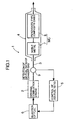
- FIG. 1 is a block diagram of a first embodiment
- FIG. 2 is a graph showing the relationship between the air-fuel ratio of an exhaust gas and the exhaust emission control rate provided by a noble metal-based three-way catalyst
- FIG. 3 is a graph showing the relationship between the air-fuel ratio of an exhaust gas and the exhaust emission control rate provided by a perovskite-type double oxide
- FIG. 4 is a graph showing changes in the air-fuel ratio of exhaust gas at the inlet of a conventional catalyst section with the passage of time
- FIG. 5 is a graph showing changes in the air-fuel ratio of exhaust gas at the outlet of the conventional catalyst section with the passage of time
- FIG. 1 is a block diagram of a first embodiment
- FIG. 2 is a graph showing the relationship between the air-fuel ratio of an exhaust gas and the exhaust emission control rate provided by a noble metal-based three-way catalyst
- FIG. 3 is a graph showing the relationship between the air-fuel ratio of an exhaust gas and the exhaust emission control rate provided by a perovskite
- FIG. 6 is a graph showing changes in the air-fuel ratio of exhaust gas at the outlet of a first catalyst section with the passage of time;
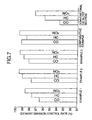
- FIG. 7 is a graph showing an exhaust emission control rate;
- FIG. 8 is a block diagram of a second embodiment; and
- FIG. 9 is a block diagram of a third embodiment.
- an exhaust emission control system 1 includes an exhaust gas purification device 4 disposed in an exhaust pipe 3 of an internal combustion engine 2, and an air-fuel ratio control device 5 for controlling the air-fuel ratio (A/F) of an air/fuel mixture supplied to the internal combustion engine 2.
- a fuel injection device 6 injects into the internal combustion engine 2 an amount of fuel determined based on a control signal from the air-fuel ratio control device 5.
- the exhaust gas purification device 4 comprises a monolith catalyst MC that includes an oxygen storage agent (OSC agent) and a noble metal-based three-way catalyst comprising Pd, Rh, and Pt disposed at an upstream location in the exhaust gas flow, that is, the exhaust pipe 3, and that includes a perovskite-type double oxide having three-way catalytic function disposed at a downstream location in the exhaust gas flow, that is, the exhaust pipe 3.
- OSC agent oxygen storage agent
- Pd, Rh, and Pt disposed at an upstream location in the exhaust gas flow, that is, the exhaust pipe 3
- a perovskite-type double oxide having three-way catalytic function disposed at a downstream location in the exhaust gas flow, that is, the exhaust pipe 3.
- the amount C1 of Pd carried is 0.97 g/L ⁇ C1 ⁇ 1.68 g/L
- the amount C2 of Rh carried is 0.11 g/L ⁇ C2 ⁇ 0.2 g/L
- the amount C3 of Pt carried is 0.06 g/L ⁇ C3 ⁇ 0.11 g/L
- the amount C4 of the oxygen storage agent carried is 25 g/L ⁇ C4 ⁇ 75 g/L
- the amount C5 of the perovskite-type double oxide carried is 5 g/L ⁇ C5 ⁇ 15 g/L.
- the noble metal-based three-way catalyst and the oxygen storage agent are present in a first catalyst section 7 of the monolith catalyst MC, and the perovskite-type double oxide is present in a second catalyst section 8 of the monolith catalyst MC.
- an air-fuel ratio sensor (an O 2 sensor) 9 is disposed at a location upstream of the exhaust gas purification device 4, and the air-fuel ratio sensor 9 detects, in terms of an oxygen concentration, an air-fuel ratio of the exhaust gas discharged from the internal combustion engine 2 and introduced into the exhaust gas purification device 4, and thus, an air-fuel ratio of the air/fuel mixture supplied to the internal combustion engine 2.
- the detection signal is fed back to the air-fuel ratio control device 5.
- an amount of fuel to be injected is calculated, based on the detection signal, so that a target air-fuel ratio is obtained, that is, the air-fuel ratio of the exhaust gas at a location upstream of the exhaust gas purification device 4 is equal to the theoretical air-fuel ratio, and such an amount of fuel is injected from the fuel injection device 6 into the internal combustion engine 2.
- the air-fuel ratio of the exhaust gas from the internal combustion engine 2 is controlled so as to become equal to the theoretical air-fuel ratio, although the air-fuel ratio of the exhaust gas at the inlet of a purification region that includes the noble metal-based three-way catalyst, that is, the first catalyst section 7, has a relatively large variation due to various external factors and the like, since the noble metal-based three-way catalyst has a wide A/F Window, in spite of the variation it can exhibit an exhaust emission control capability.
- the oxygen storage agent exhibits an oxygen storage effect and the air-fuel ratio of the exhaust gas at the outlet of the first catalyst section 7 is thus made to converge to a substantially straight line so as to minimize the variation.
- the A/F Window of the perovskite-type double oxide of the second catalyst section 8 is considerably narrower than that of the noble metal-based three-way catalyst, the air-fuel ratio of the exhaust gas can be contained within the narrow A/F Window by the oxygen storage agent exhibiting an effect in converging the air-fuel ratio of the exhaust gas, thus allowing the perovskite-type double oxide to exhibit an excellent exhaust emission control capability.
- the perovskite-type double oxide having the three-way catalytic function has A-site defects in its crystal structure, and it is conceivable that the A-site defects are involved in purification of the exhaust gas. That is, NOx in the exhaust gas is adsorbed on the A-site defects, the O atom thereof enters the A-site defect, the bonding state of the NOx thereby becomes electronically unstable, and the bond between the O atom and the N atom is broken.
- the N atom is reduced to become N 2 , and the O atom remaining in the A-site defect adsorbs HC, CO, and H 2 in the exhaust gas and leaves the A-site defect, thus regenerating the A-site defect and at the same time oxidizing the HC, CO, and H 2 into H 2 O and CO 2 .
- Pd, Rh, and Pt can exhibit an exhaust emission control capability even in a state in which the exhaust gas temperature is low when the internal combustion engine is started and the perovskite-type double oxide is not yet activated. Furthermore, when the exhaust gas flow rate is high (high SV), the perovskite-type double oxide tends to have a low NOx control capability, but this can be compensated for by Rh and Pt.
- oxygen storage agent a known compound such as CeZrO or CeO 2 is used.
- a perovskite-type double oxide containing a lanthanide mixture extracted from bastnaesite it may be one represented by the general formula A a-x B a-x MO b , wherein A is the lanthanide mixture extracted from the bastnaesite; B is a bivalent or monovalent cation; M is at least one element selected from the group consisting of elements having atomic numbers of 22 to 30, 40 to 51 and 73 to 80; a is 1 or 2, b is 3 when a is 1, or 4 when a is 2; and x is in the range of 0 ⁇ x ⁇ 0.7.
- the perovskite-type double oxides include, for example, Ln 0.6 Ca 0.4 CoO 3 (Ln is a lanthanoid and includes La, Ce, Pr, Nd or the like, and hereinafter referred to likewise), Ln 0.83 Sr 0.17 MnO 3 , Ln 0.7 Sr 0.3 CrO 3 , Ln 0.6 Ca 0.4 Fe 0.8 Mn 0.2 O 3 , Ln 0.8 Sr 0.2 Mn 0.9 Ni 0.04 Ru 0.06 O 3 , Ln 0.8 K 0.2 Mn 0.95 Ru 0.05 O 3 , Ln 0.7 Sr 0.3 Cr 0.95 RU 0.05 O 3 , LnNiO 3 , Ln 2 (Cu 0.6 Co 0.2 Ni 0.2 )O 4 , Ln 0.8 K 0.2 Mn 0.95 Ru 0.05 O 3 and the like.
- Such perovskite-type double oxides are disclosed in the specification and drawings of International Application Laid-open No. W097/37760. Any of the perovskite-type double oxides disclosed in this International Application can be used in the present invention.
- Such an air-fuel control device 5 as described above is disclosed in Japanese Patent Application Laid-open No. 60-1342 filed by the present applicant, and an electronic control unit 5 disclosed in this publication is used in the embodiments of the present invention.
- the conventional catalyst section was incorporated in an exhaust pipe of a 1.6 L gasoline internal combustion engine, and an exhaust emission control bench test was carried out.
- An air-fuel ratio sensor was disposed in the exhaust pipe at a location upstream of the conventional catalyst section, as in FIG. 1.
- Another exhaust emission control bench test was carried out in a similar manner for the second catalyst section 8.
- Fig. 2 shows the relationship between the air-fuel ratio of an exhaust gas and the exhaust emission control rate for the conventional catalyst section
- the A/F Window in the perovskite-type double oxide in the second catalyst section 8 is narrower than that of the noble metal-based three-way catalyst in the conventional catalyst section, and is about 18 % of that of the noble metal-based three-way catalyst.
- the conventional catalyst section was incorporated in an exhaust pipe of an automobile having a 1.6 L gasoline engine mounted therein, and first and second air-fuel ratio sensors were disposed in the exhaust pipe at locations upstream and downstream of the conventional catalyst section. Changes in the air-fuel ratio were measured with the passage of time at the inlet and the outlet of the conventional catalyst section. The detection signal from the second air-fuel ratio sensor disposed at the downstream location was used to correct the amount of fuel to be injected, which was calculated based on a result of the detection by the first air-fuel ratio sensor.
- Fig. 4 shows changes in the air-fuel ratio of exhaust gas at the inlet of the conventional catalyst section with the passage of time. It can be seen from Fig. 4 that a relatively large variation was generated in the air-fuel ratio of exhaust gas at the inlet, as described above.
- Fig. 5 shows changes in the air-fuel ratio of exhaust gas at the outlet of the conventional catalyst section with the passage of time. It can be seen from Fig. 5 that the air-fuel ratio of exhaust gas at the outlet was made to converge to a substantially straight line, as described above, by the oxygen storage effect of CeZrO.
- the second catalyst section 8 can exhibit a high exhaust emission control rate.
- a first catalyst section 7 was prepared in which Pt, Pd, Rh, and CeZrO were carried on ⁇ -Al 2 O 3 , and this was retained on a 0.7 L honeycomb support.
- the amount C1 of Pd carried was 0.97 g/L
- the amount C2 of Rh carried was 0.11 g/L
- the amount C3 of Pt carried was 0.06 g/L
- the amount C4 of CeZrO carried was 50 g/L.
- This first catalyst section 7 was subjected to an actual automobile test in the same manner as above to measure changes in the air-fuel ratio of exhaust gas at the outlet of the first catalyst section 7 with the passage of time.
- Fig. 6 shows changes in the air-fuel ratio of exhaust gas at the outlet of the first catalyst section 7 with the passage of time.
- the air-fuel ratio of exhaust gas at the outlet was made to converge to a substantially straight line, as described above, by the oxygen storage effect of CeZrO.
- the converged air-fuel ratio of the exhaust gas was contained within the A/F Window of the perovskite-type double oxide shown in FIG. 3, i.e., 14.73 ⁇ A/F ⁇ 14.76.
- first catalyst sections 7 were prepared by changing the amounts of Pd, Rh, and Pt carried, and four types of second catalyst sections 8 were prepared by changing the amount of perovskite-type double oxide (Ln 0.83 Sr 0,17 MnO 3 ) of the same type as above.
- Monolith catalysts MC of Examples 1 to 3 and a Comparative Example were then prepared by combining the first and second catalyst sections 7, 8.
- TABLE 1 shows the structures of Examples 1 to 3 and the Comparative Example.
- the structure of the conventional catalyst section is also given in TABLE 1 for reference.
- FIG. 7 is a graph showing the exhaust emission control rate of Examples 1 to 3 and the like, based on the results shown in TABLE 2. As is clear from TABLE 2 and FIG. 7, Examples 1 to 3 showed excellent exhaust emission control rates compared with the conventional catalyst section having no second catalyst section 8 and, moreover, the amount of Pd was less by about 17% to about 52%. The exhaust emission control rates of Examples 1 to 3 were close to that of the Comparative Example and, moreover, the amount of Pd was less than that of the Comparative Example by about 17%.
- FIG. 8 shows a second embodiment.
- a first catalyst section 7 is used mainly to regulate the air-fuel ratio of exhaust gas that is to be introduced into a second catalyst section 8. Purification of the exhaust gas is carried out mainly by the second catalyst section 8.
- the first catalyst section 7 can be constructed at a small size, whereby the amount of noble metal-based three-way catalyst used can be decreased.
- FIG. 9 shows a third embodiment.
- a first catalyst section 7 is constructed at a small size and disposed in an exhaust pipe 3 at a location immediately downstream of an internal combustion engine 2. With this construction, the first catalyst section 7 is activated soon after starting the engine and exhibits an exhaust emission control capability. After the engine is warmed up, the first catalyst section 7 is used to regulate the air-fuel ratio of exhaust gas that is to be introduced into a second catalyst section 8, and purification of the exhaust gas is thus conducted solely by the second catalyst section 8.
Landscapes
- Chemical & Material Sciences (AREA)
- Engineering & Computer Science (AREA)
- Chemical Kinetics & Catalysis (AREA)
- Materials Engineering (AREA)
- Organic Chemistry (AREA)
- Health & Medical Sciences (AREA)
- Combustion & Propulsion (AREA)
- Biomedical Technology (AREA)
- Environmental & Geological Engineering (AREA)
- Analytical Chemistry (AREA)
- General Chemical & Material Sciences (AREA)
- Oil, Petroleum & Natural Gas (AREA)
- Exhaust Gas Treatment By Means Of Catalyst (AREA)
- Catalysts (AREA)
- Exhaust Gas After Treatment (AREA)
Abstract
Description
| Monolith catalyst | First catalyst section (g/L) | Second catalyst section (g/L) | |||
| Pd | Rh | Pt | CeZrO | ||
| Example 1 | 0.97 | 0.11 | 0.06 | 50 | 7.8 |
| Example 2 | 1.45 | 0.17 | 0.10 | 50 | 11.7 |
| Example 3 | 1.68 | 0.20 | 0.11 | 50 | 13.6 |
| Comparative Example | 2.02 | 0.21 | 0.11 | 50 | 13.6 |
| Conventional catalyst section | 2.02 | 0.10 | - | 50 | - |
| Monolith catalyst | Exhaust emission control rate (%) | ||
| CO | HC | NOx | |
| Example 1 | 96.5 | 97.6 | 98.6 |
| Example 2 | 97.7 | 99.0 | 99.5 |
| Example 3 | 98.1 | 98.8 | 99.4 |
| Comparative Example | 99.2 | 98.4 | 99.5 |
| Conventional catalyst section | 93.7 | 95.8 | 97.2 |
Claims (4)
- An exhaust emission control system for an internal combustion engine, the system comprising a monolith catalyst (MC) that comprises an oxygen storage agent and a noble metal-based three-way catalyst comprising Pd, Rh, and Pt disposed at an upstream location in the exhaust gas flow in the internal combustion engine (2), and a perovskite-type double oxide having a three-way catalytic function disposed at a downstream location in the exhaust gas flow, the amount C1 of Pd carried being 0.97 g/L ≤ C1 ≤ 1.68 g/L, the amount C2 of Rh carried being 0.11 g/L ≤ C2 ≤ 0.2 g/L, the amount C3 of Pt carried being 0.06 g/L ≤ C3 ≤ 0.11 g/L, the amount C4 of the oxygen storage agent carried being 25 g/L ≤ C4 ≤ 75 g/L, and the amount C5 of the perovskite-type double oxide carried being 5 g/L ≤ C5 ≤ 15 g/L.
- An exhaust emission control system for an internal combustion engine, the system comprising a monolith catalyst (MC) that comprises a noble metal-based three-way catalyst disposed at an upstream location in the exhaust gas flow in the internal combustion engine (2), and a perovskite-type double oxide having three-way catalytic function disposed at a downstream location in the exhaust gas flow, wherein an oxygen storage agent is disposed together with the noble metal-based three-way catalyst, and the amount C4 of the oxygen storage agent carried is 25 g/L ≤ C4 ≤ 75 g/L.
- An exhaust emission control system for an internal combustion engine, the system comprising a first catalyst section (7) comprising a noble metal-based three-way catalyst and an oxygen storage agent disposed at an upstream location in the exhaust gas flow in the internal combustion engine (2), and a second catalyst section (8) comprising a perovskite-type double oxide having a three-way catalytic function disposed at a downstream location in the exhaust gas flow, the oxygen storage agent having a function of regulating the air-fuel ratio of an exhaust gas that is to be introduced into the second catalyst section (8) so as to fall within an A/F Window of the perovskite-type double oxide.
- The exhaust emission control system for an internal combustion engine according to Claim 1, 2 or 3, wherein the perovskite-type double oxide includes a lanthanide mixture extracted from bastnaesite.
Applications Claiming Priority (5)
| Application Number | Priority Date | Filing Date | Title |
|---|---|---|---|
| JP2000271401 | 2000-09-07 | ||
| JP2000271401 | 2000-09-07 | ||
| JP2001106327 | 2001-04-04 | ||
| JP2001106327A JP3715211B2 (en) | 2000-09-07 | 2001-04-04 | Exhaust gas purification device for internal combustion engine |
| PCT/JP2001/007279 WO2002020140A1 (en) | 2000-09-07 | 2001-08-24 | Device for clarifying exhaust gas from internal combustion engine |
Publications (3)
| Publication Number | Publication Date |
|---|---|
| EP1354620A1 true EP1354620A1 (en) | 2003-10-22 |
| EP1354620A4 EP1354620A4 (en) | 2006-07-19 |
| EP1354620B1 EP1354620B1 (en) | 2008-07-09 |
Family
ID=26599432
Family Applications (1)
| Application Number | Title | Priority Date | Filing Date |
|---|---|---|---|
| EP01958484A Expired - Lifetime EP1354620B1 (en) | 2000-09-07 | 2001-08-24 | Device for clarifying exhaust gas from internal combustion engine |
Country Status (6)
| Country | Link |
|---|---|
| US (1) | US7157405B2 (en) |
| EP (1) | EP1354620B1 (en) |
| JP (1) | JP3715211B2 (en) |
| CA (1) | CA2421404C (en) |
| DE (1) | DE60134783D1 (en) |
| WO (1) | WO2002020140A1 (en) |
Families Citing this family (8)
| Publication number | Priority date | Publication date | Assignee | Title |
|---|---|---|---|---|
| KR100581290B1 (en) * | 2003-12-10 | 2006-05-17 | 한국전자통신연구원 | Base station apparatus and terminal for location measurement, location measurement method |
| JP4654746B2 (en) * | 2005-04-14 | 2011-03-23 | マツダ株式会社 | Exhaust gas purification catalyst device |
| JP2009180202A (en) * | 2008-01-31 | 2009-08-13 | Honda Motor Co Ltd | Vehicle exhaust gas purification device |
| JP5339302B2 (en) * | 2008-02-27 | 2013-11-13 | 独立行政法人産業技術総合研究所 | Metal recovery method |
| WO2010041525A1 (en) | 2008-10-09 | 2010-04-15 | 独立行政法人産業技術総合研究所 | Composition for collecting metal component |
| JP5652765B2 (en) | 2010-03-31 | 2015-01-14 | 独立行政法人産業技術総合研究所 | Metal component recovery agent and metal component recovery method |
| EP2650042B2 (en) * | 2012-04-13 | 2020-09-02 | Umicore AG & Co. KG | Pollutant abatement system for gasoline vehicles |
| WO2015174102A1 (en) * | 2014-05-13 | 2015-11-19 | 日産自動車株式会社 | Exhaust gas purification catalyst |
Family Cites Families (17)
| Publication number | Priority date | Publication date | Assignee | Title |
|---|---|---|---|---|
| JPS601342A (en) | 1983-06-17 | 1985-01-07 | Honda Motor Co Ltd | Air-fuel ratio feed-back control method for internal-combustion engine |
| JPS6377543A (en) * | 1986-09-17 | 1988-04-07 | Toyota Motor Corp | Catalyst for purifying exhaust gas |
| JPS63267805A (en) * | 1987-04-23 | 1988-11-04 | Mitsubishi Heavy Ind Ltd | Oxidizing catalyst for high temperature service |
| JPH0394818A (en) * | 1989-09-07 | 1991-04-19 | Nippon Shokubai Kagaku Kogyo Co Ltd | Catalytic converter |
| JPH06304449A (en) * | 1993-04-23 | 1994-11-01 | Toyota Central Res & Dev Lab Inc | Nitrogen oxide removal device |
| DE69503527T2 (en) * | 1994-01-20 | 1999-04-29 | Toyota Jidosha K.K., Toyota, Aichi | Catalytic converter for cleaning exhaust gases |
| US6497851B1 (en) * | 1994-12-06 | 2002-12-24 | Englehard Corporation | Engine exhaust treatment apparatus and method of use |
| US5977017A (en) * | 1996-04-10 | 1999-11-02 | Catalytic Solutions, Inc. | Perovskite-type metal oxide compounds |
| US6087298A (en) * | 1996-05-14 | 2000-07-11 | Engelhard Corporation | Exhaust gas treatment system |
| WO1998011978A1 (en) * | 1996-09-19 | 1998-03-26 | Precision Combustion Inc. | Catalytic method |
| JP4092441B2 (en) * | 1997-02-24 | 2008-05-28 | 日産自動車株式会社 | Exhaust gas purification catalyst |
| JP4006061B2 (en) * | 1997-07-28 | 2007-11-14 | 日本碍子株式会社 | Exhaust gas purification system |
| JP4450396B2 (en) * | 1997-10-08 | 2010-04-14 | 日産自動車株式会社 | Exhaust gas purification device using NOx occlusion reduction type three-way catalyst |
| KR100326747B1 (en) * | 1998-03-09 | 2002-03-13 | 하나와 요시카즈 | Device for Purifying Oxygen Rich Exhaust Gas |
| US6634168B1 (en) * | 1998-10-19 | 2003-10-21 | Nissan Motor Co., Ltd. | Exhaust gas purification system |
| JP3952617B2 (en) * | 1998-12-11 | 2007-08-01 | 株式会社日立製作所 | Exhaust gas purification device, exhaust gas purification method and exhaust gas purification catalyst for internal combustion engine |
| US6375910B1 (en) * | 1999-04-02 | 2002-04-23 | Engelhard Corporation | Multi-zoned catalytic trap and methods of making and using the same |
-
2001
- 2001-04-04 JP JP2001106327A patent/JP3715211B2/en not_active Expired - Fee Related
- 2001-08-24 EP EP01958484A patent/EP1354620B1/en not_active Expired - Lifetime
- 2001-08-24 US US10/362,967 patent/US7157405B2/en not_active Expired - Fee Related
- 2001-08-24 CA CA002421404A patent/CA2421404C/en not_active Expired - Fee Related
- 2001-08-24 DE DE60134783T patent/DE60134783D1/en not_active Expired - Lifetime
- 2001-08-24 WO PCT/JP2001/007279 patent/WO2002020140A1/en not_active Ceased
Also Published As
| Publication number | Publication date |
|---|---|
| US7157405B2 (en) | 2007-01-02 |
| WO2002020140A1 (en) | 2002-03-14 |
| JP3715211B2 (en) | 2005-11-09 |
| CA2421404A1 (en) | 2003-03-06 |
| CA2421404C (en) | 2006-08-08 |
| US20040038814A1 (en) | 2004-02-26 |
| JP2002155734A (en) | 2002-05-31 |
| DE60134783D1 (en) | 2008-08-21 |
| EP1354620A4 (en) | 2006-07-19 |
| EP1354620B1 (en) | 2008-07-09 |
Similar Documents
| Publication | Publication Date | Title |
|---|---|---|
| US6823662B1 (en) | Exhaust gas purifying system | |
| USRE44802E1 (en) | Cerium-zirconium composite metal oxide | |
| CN101711944B (en) | Method and architecture for oxidizing nitric oxide in exhaust gas from hydrocarbon fuel source with a fuel lean combustion mixture | |
| US20160288096A1 (en) | Exhaust gas control catalyst | |
| US20050049143A1 (en) | Exhaust gas treatment catalyst and exhaust gas treatment method | |
| EP1064985B1 (en) | Exhaust gas purifying system | |
| EP3925701A1 (en) | Catalyst for purifying exhaust gas | |
| EP4166229A1 (en) | Exhaust gas purification catalyst | |
| EP0905354A2 (en) | Exhaust gas purifying catalyst and system and method of producing the catalyst | |
| US20220154621A1 (en) | Exhaust Gas Purification Catalyst | |
| US7157405B2 (en) | Device for clarifying exhaust gas from internal combustion engine | |
| EP4205848A1 (en) | Exhaust gas purification catalyst | |
| EP1516855A1 (en) | Cerium-Zirconium composite metal oxide with a cerium oxide core surrounded by zirconium oxide | |
| CA2525808C (en) | Catalyst for purifying exhaust gases and method of evaluating low-temperature purifying ability of the same | |
| EP1867389A1 (en) | Apparatus for purifying exhaust gas and catalyst for purifying exhaust gas | |
| JP4450396B2 (en) | Exhaust gas purification device using NOx occlusion reduction type three-way catalyst | |
| JP2009178625A (en) | Exhaust gas purification device | |
| JP2010227799A (en) | Exhaust gas purification catalyst | |
| JP3696524B2 (en) | Exhaust gas purification device for lean burn engine | |
| US20260097363A1 (en) | Catalyst for Exhaust Gas Purification | |
| JP4138277B2 (en) | Exhaust gas purification system for internal combustion engine | |
| CN116438139B (en) | Catalysts for exhaust gas purification | |
| JPH11247654A (en) | Exhaust gas purifier using NOx storage reduction type three-way catalyst | |
| JPH09225306A (en) | Exhaust gas purification catalyst and method for producing the same | |
| CN120693210A (en) | Catalysts for exhaust gas purification |
Legal Events
| Date | Code | Title | Description |
|---|---|---|---|
| PUAI | Public reference made under article 153(3) epc to a published international application that has entered the european phase |
Free format text: ORIGINAL CODE: 0009012 |
|
| 17P | Request for examination filed |
Effective date: 20030401 |
|
| AK | Designated contracting states |
Kind code of ref document: A1 Designated state(s): AT BE CH CY DE DK ES FI FR GB GR IE IT LI LU MC NL PT SE TR |
|
| RBV | Designated contracting states (corrected) |
Designated state(s): AT BE CH DE FR GB LI |
|
| A4 | Supplementary search report drawn up and despatched |
Effective date: 20060619 |
|
| 17Q | First examination report despatched |
Effective date: 20061214 |
|
| GRAP | Despatch of communication of intention to grant a patent |
Free format text: ORIGINAL CODE: EPIDOSNIGR1 |
|
| GRAS | Grant fee paid |
Free format text: ORIGINAL CODE: EPIDOSNIGR3 |
|
| GRAA | (expected) grant |
Free format text: ORIGINAL CODE: 0009210 |
|
| AK | Designated contracting states |
Kind code of ref document: B1 Designated state(s): DE FR GB |
|
| RBV | Designated contracting states (corrected) |
Designated state(s): DE FR GB |
|
| REG | Reference to a national code |
Ref country code: GB Ref legal event code: FG4D |
|
| REF | Corresponds to: |
Ref document number: 60134783 Country of ref document: DE Date of ref document: 20080821 Kind code of ref document: P |
|
| PLBE | No opposition filed within time limit |
Free format text: ORIGINAL CODE: 0009261 |
|
| STAA | Information on the status of an ep patent application or granted ep patent |
Free format text: STATUS: NO OPPOSITION FILED WITHIN TIME LIMIT |
|
| 26N | No opposition filed |
Effective date: 20090414 |
|
| REG | Reference to a national code |
Ref country code: GB Ref legal event code: 746 Effective date: 20120521 |
|
| REG | Reference to a national code |
Ref country code: DE Ref legal event code: R084 Ref document number: 60134783 Country of ref document: DE Effective date: 20120523 |
|
| PGFP | Annual fee paid to national office [announced via postgrant information from national office to epo] |
Ref country code: GB Payment date: 20120822 Year of fee payment: 12 |
|
| PGFP | Annual fee paid to national office [announced via postgrant information from national office to epo] |
Ref country code: FR Payment date: 20120823 Year of fee payment: 12 |
|
| GBPC | Gb: european patent ceased through non-payment of renewal fee |
Effective date: 20130824 |
|
| REG | Reference to a national code |
Ref country code: FR Ref legal event code: ST Effective date: 20140430 |
|
| PG25 | Lapsed in a contracting state [announced via postgrant information from national office to epo] |
Ref country code: GB Free format text: LAPSE BECAUSE OF NON-PAYMENT OF DUE FEES Effective date: 20130824 |
|
| PG25 | Lapsed in a contracting state [announced via postgrant information from national office to epo] |
Ref country code: FR Free format text: LAPSE BECAUSE OF NON-PAYMENT OF DUE FEES Effective date: 20130902 |
|
| PGFP | Annual fee paid to national office [announced via postgrant information from national office to epo] |
Ref country code: DE Payment date: 20170815 Year of fee payment: 17 |
|
| REG | Reference to a national code |
Ref country code: DE Ref legal event code: R119 Ref document number: 60134783 Country of ref document: DE |
|
| PG25 | Lapsed in a contracting state [announced via postgrant information from national office to epo] |
Ref country code: DE Free format text: LAPSE BECAUSE OF NON-PAYMENT OF DUE FEES Effective date: 20190301 |