EP1353130B1 - Einrichtung zum Eisfreihalten eines Wärmeaustauscherapparats - Google Patents
Einrichtung zum Eisfreihalten eines Wärmeaustauscherapparats Download PDFInfo
- Publication number
- EP1353130B1 EP1353130B1 EP03008249A EP03008249A EP1353130B1 EP 1353130 B1 EP1353130 B1 EP 1353130B1 EP 03008249 A EP03008249 A EP 03008249A EP 03008249 A EP03008249 A EP 03008249A EP 1353130 B1 EP1353130 B1 EP 1353130B1
- Authority
- EP
- European Patent Office
- Prior art keywords
- heat exchanger
- heat pump
- heat
- circuit
- condenser
- Prior art date
- Legal status (The legal status is an assumption and is not a legal conclusion. Google has not performed a legal analysis and makes no representation as to the accuracy of the status listed.)
- Expired - Lifetime
Links
Images

Classifications
-
- F—MECHANICAL ENGINEERING; LIGHTING; HEATING; WEAPONS; BLASTING
- F24—HEATING; RANGES; VENTILATING
- F24D—DOMESTIC- OR SPACE-HEATING SYSTEMS, e.g. CENTRAL HEATING SYSTEMS; DOMESTIC HOT-WATER SUPPLY SYSTEMS; ELEMENTS OR COMPONENTS THEREFOR
- F24D19/00—Details
- F24D19/0095—Devices for preventing damage by freezing
-
- F—MECHANICAL ENGINEERING; LIGHTING; HEATING; WEAPONS; BLASTING
- F24—HEATING; RANGES; VENTILATING
- F24D—DOMESTIC- OR SPACE-HEATING SYSTEMS, e.g. CENTRAL HEATING SYSTEMS; DOMESTIC HOT-WATER SUPPLY SYSTEMS; ELEMENTS OR COMPONENTS THEREFOR
- F24D5/00—Hot-air central heating systems; Exhaust gas central heating systems
- F24D5/02—Hot-air central heating systems; Exhaust gas central heating systems operating with discharge of hot air into the space or area to be heated
-
- F—MECHANICAL ENGINEERING; LIGHTING; HEATING; WEAPONS; BLASTING
- F24—HEATING; RANGES; VENTILATING
- F24D—DOMESTIC- OR SPACE-HEATING SYSTEMS, e.g. CENTRAL HEATING SYSTEMS; DOMESTIC HOT-WATER SUPPLY SYSTEMS; ELEMENTS OR COMPONENTS THEREFOR
- F24D5/00—Hot-air central heating systems; Exhaust gas central heating systems
- F24D5/12—Hot-air central heating systems; Exhaust gas central heating systems using heat pumps
-
- F—MECHANICAL ENGINEERING; LIGHTING; HEATING; WEAPONS; BLASTING
- F24—HEATING; RANGES; VENTILATING
- F24F—AIR-CONDITIONING; AIR-HUMIDIFICATION; VENTILATION; USE OF AIR CURRENTS FOR SCREENING
- F24F12/00—Use of energy recovery systems in air conditioning, ventilation or screening
- F24F12/001—Use of energy recovery systems in air conditioning, ventilation or screening with heat-exchange between supplied and exhausted air
- F24F12/002—Use of energy recovery systems in air conditioning, ventilation or screening with heat-exchange between supplied and exhausted air using an intermediate heat-transfer fluid
- F24F12/003—Use of energy recovery systems in air conditioning, ventilation or screening with heat-exchange between supplied and exhausted air using an intermediate heat-transfer fluid using a heat pump
-
- F—MECHANICAL ENGINEERING; LIGHTING; HEATING; WEAPONS; BLASTING
- F24—HEATING; RANGES; VENTILATING
- F24F—AIR-CONDITIONING; AIR-HUMIDIFICATION; VENTILATION; USE OF AIR CURRENTS FOR SCREENING
- F24F5/00—Air-conditioning systems or apparatus not covered by F24F1/00 or F24F3/00, e.g. using solar heat or combined with household units such as an oven or water heater
- F24F5/0096—Air-conditioning systems or apparatus not covered by F24F1/00 or F24F3/00, e.g. using solar heat or combined with household units such as an oven or water heater combined with domestic apparatus
-
- F—MECHANICAL ENGINEERING; LIGHTING; HEATING; WEAPONS; BLASTING
- F24—HEATING; RANGES; VENTILATING
- F24D—DOMESTIC- OR SPACE-HEATING SYSTEMS, e.g. CENTRAL HEATING SYSTEMS; DOMESTIC HOT-WATER SUPPLY SYSTEMS; ELEMENTS OR COMPONENTS THEREFOR
- F24D2220/00—Components of central heating installations excluding heat sources
- F24D2220/07—Heat pipes
-
- F—MECHANICAL ENGINEERING; LIGHTING; HEATING; WEAPONS; BLASTING
- F24—HEATING; RANGES; VENTILATING
- F24F—AIR-CONDITIONING; AIR-HUMIDIFICATION; VENTILATION; USE OF AIR CURRENTS FOR SCREENING
- F24F11/00—Control or safety arrangements
- F24F11/30—Control or safety arrangements for purposes related to the operation of the system, e.g. for safety or monitoring
- F24F11/41—Defrosting; Preventing freezing
-
- Y—GENERAL TAGGING OF NEW TECHNOLOGICAL DEVELOPMENTS; GENERAL TAGGING OF CROSS-SECTIONAL TECHNOLOGIES SPANNING OVER SEVERAL SECTIONS OF THE IPC; TECHNICAL SUBJECTS COVERED BY FORMER USPC CROSS-REFERENCE ART COLLECTIONS [XRACs] AND DIGESTS
- Y02—TECHNOLOGIES OR APPLICATIONS FOR MITIGATION OR ADAPTATION AGAINST CLIMATE CHANGE
- Y02B—CLIMATE CHANGE MITIGATION TECHNOLOGIES RELATED TO BUILDINGS, e.g. HOUSING, HOUSE APPLIANCES OR RELATED END-USER APPLICATIONS
- Y02B30/00—Energy efficient heating, ventilation or air conditioning [HVAC]
- Y02B30/13—Hot air central heating systems using heat pumps
-
- Y—GENERAL TAGGING OF NEW TECHNOLOGICAL DEVELOPMENTS; GENERAL TAGGING OF CROSS-SECTIONAL TECHNOLOGIES SPANNING OVER SEVERAL SECTIONS OF THE IPC; TECHNICAL SUBJECTS COVERED BY FORMER USPC CROSS-REFERENCE ART COLLECTIONS [XRACs] AND DIGESTS
- Y02—TECHNOLOGIES OR APPLICATIONS FOR MITIGATION OR ADAPTATION AGAINST CLIMATE CHANGE
- Y02B—CLIMATE CHANGE MITIGATION TECHNOLOGIES RELATED TO BUILDINGS, e.g. HOUSING, HOUSE APPLIANCES OR RELATED END-USER APPLICATIONS
- Y02B30/00—Energy efficient heating, ventilation or air conditioning [HVAC]
- Y02B30/52—Heat recovery pumps, i.e. heat pump based systems or units able to transfer the thermal energy from one area of the premises or part of the facilities to a different one, improving the overall efficiency
-
- Y—GENERAL TAGGING OF NEW TECHNOLOGICAL DEVELOPMENTS; GENERAL TAGGING OF CROSS-SECTIONAL TECHNOLOGIES SPANNING OVER SEVERAL SECTIONS OF THE IPC; TECHNICAL SUBJECTS COVERED BY FORMER USPC CROSS-REFERENCE ART COLLECTIONS [XRACs] AND DIGESTS
- Y02—TECHNOLOGIES OR APPLICATIONS FOR MITIGATION OR ADAPTATION AGAINST CLIMATE CHANGE
- Y02B—CLIMATE CHANGE MITIGATION TECHNOLOGIES RELATED TO BUILDINGS, e.g. HOUSING, HOUSE APPLIANCES OR RELATED END-USER APPLICATIONS
- Y02B30/00—Energy efficient heating, ventilation or air conditioning [HVAC]
- Y02B30/56—Heat recovery units
Definitions
- the invention relates to a device for defrosting or Eiskahalten a heat exchanger apparatus, on the heated rooms outside air can be supplied and room air is discharged.
- Such a heat exchanger apparatus is described in the air conditioner of DE 197 02 903 A1.
- the heat exchanger apparatus is an air / air cross flow or cross countercurrent or countercurrent heat exchanger which transfers the heat of the exhaust air to the supplied outside air.
- a heat pump is provided for space heating, which works with an air-refrigerant evaporator. This is in the exhaust air stream of the heat exchanger apparatus. It is described that the evaporator can freeze. To defrost it, the heat pump cycle is switched. During defrosting the heat recovery is interrupted for the Nutz Vietnamese.
- GB 1551647 discloses a plant for recovering heat from exhaust air, wherein, knowing the problem of icing of a heat exchanger, a heat exchanger in the fresh air branch is arranged upstream of the air-air heat exchanger. This heat exchanger receives the heat necessary for preheating the fresh air through a second coupled thereto heat exchanger, which is arranged in the exhaust air branch of this device.
- the two heat exchangers are coupled together as an evaporator and condenser in a closed and a heat transfer fluid system.
- the object of the invention is to propose a device with which the heat exchanger apparatus can be defrosted with improved efficiency or kept free of ice.
- a heat exchanger apparatus on the heated rooms outside air can be supplied and air is discharged, in which a heat exchanger (6) and in the outside air flow (AU) of the Heat exchanger apparatus (1) arranged heating register (7) to a, a medium leading defrosting circuit (5) are connected, the heat exchanger in the heating circuit of the rooms is arranged, wherein the medium evaporates in the heat exchanger and condenses in the heating coil.
- the defrosting circuit works on the principle of a heat pipe.
- the medium is evaporated in the heat exchanger lying in the heating circuit and transfers heat to the heating coil and thus the supplied outside air flow, where it condenses in the heating coil and flows back to the heat exchanger. There must be no additional energy supplied to the device.
- the medium circulates in the defrost cycle under gravity. An electric heating of the heating register is not necessary. An elaborate soil heat exchanger for Eiszyhalten the air / air heat exchanger is unnecessary.
- the heating coil Since the heating coil is not flowed through by water but by a medium which does not change into the solid state even at temperatures below 0 ° C., there is no risk that the heating coil will freeze.
- the medium is a refrigerant which evaporates at the flow temperature or the return temperature of the heating circuit of the rooms.
- Suitable medium is a refrigerant, as it is also used in heat pumps or refrigeration units.
- the heat exchanger apparatus is defrosted with room air. It is therefore not necessary to switch or switch off air flows in the heat exchanger apparatus.
- This is particularly favorable in so-called passive houses, because no negative pressure in the house is generated by the described device and then uncontrolled outdoor air can flow into the house as a result of leaks in the building envelope, whereby the energy balance of the house would be strongly negatively affected.
- the supply air volume flow is not interrupted. This is important for the ventilation of a passive house, because there the supply air volume often takes over the heating of the rooms.
- a ventilation system of a building has for heat recovery on a heat exchanger apparatus 1, which may be an air / air cross-flow or cross-countercurrent heat exchanger with supply fan and exhaust fan.
- a heat exchanger apparatus 1 By the heat exchanger apparatus 1 outside air AU is supplied from the environment as supply air to the rooms of the building. From the rooms exhaust air AB is discharged. Heat of the exhaust air AB is transferred to the supply air ZU. The cooled exhaust air is then transported outside as exhaust air.
- the ventilation system has to heat the rooms on a heating circuit 2, in which usually conveys a circulating pump 3 from a not shown solar, oil or gas heater heated water to radiators, not shown.
- the radiators can be installed in the rooms and / or arranged in the supply air flow ZU.
- the heat exchanger apparatus 1 can freeze.
- a device 4 is provided.
- the device 4 forms a defrost 5, in which a heat exchanger 6, a heater 7 and a turn-off Abtau Vietnameseventil 8, in particular solenoid valve, are arranged.
- the heat exchanger 6 is arranged in the return or flow of the heating circuit 2.
- the heater 7 is located in the outside air flow AU.
- the Abtau Vietnamese 5 includes a medium which evaporates in the heat exchanger 6 at the temperature of the heating circuit 2, then flows in vapor form to the heating coil 7 where it gives off heat to the cold outside air AU, thereby condensing and flowing back to the heat exchanger 6 by gravity.
- the device thus works as a heat pipe (heat pipe). As a result, from the heat of the heating circuit 2, the heat exchanger apparatus 1 is kept free of ice or defrosted.
- the Abtaunik 5 also works when the circulation pump 3 fails, as well as due to the temperature and density differences of the water in the heating circuit 2 adjusts a flow from which the heat exchanger 6 can transfer heat to the heater 7.
- the defrost cycle valve 8 is closed unless there is a risk of icing of the heat exchanger apparatus 1. Switching on and off can be done outside temperature dependent.
- the heating circuit 2 is heated in a conventional manner by a condenser 9 of a heat pump 10 having a compressor 11, an air-refrigerant evaporator 12 and an expansion valve 13.
- a further valve 14 is provided in the heat pump circuit.
- the condenser 9 also forms the heat exchanger 6 of the Abtau Vietnamesees 5.
- the refrigerant of the heat pump cycle is the medium of the Abtau Vietnamesees.
- the heating register 7 is connected to the condenser 9.
- the defrost circuit valve 8 is closed and the further valve 14 is opened.
- the heating register 7 lies in the flow direction of the refrigerant behind the condenser 9 and is heated by the refrigerant, so that it transfers heat to the outside air AU. Thereby, the heat exchanger apparatus 1 is kept ice-free and the refrigerant is supercooled. This is described in the earlier patent application 101 03 150.5.
- the other valve 14 is closed. This is in the flow direction of the refrigerant before the expansion valve 13.
- the further valve 14 may be a pump-down valve. Depending on the refrigerant charge and internal volumes of the aggregates, the refrigerant can now be pumped via the further valve 14 from the low pressure side of the heat pump circuit still on the high pressure side, so that a sufficient amount of working fluid is available for the heat pipe effect.
- the defrost cycle valve 8 is opened.
- FIG. 3 corresponds to that of Figure 2, but with the heater 7 is connected in parallel to the condenser 9. If the Abtau Vietnamese disconnectil 8 is opened and the heat pump 10 is turned off, then the Abtau Vietnamese 5 operates in the manner described. If the heat pump 10 is in operation and the defrost cycle valve 8 is opened, then the condenser 9 and the heating register 7 are flowed through in parallel by the refrigerant. If the Abtau Vietnameseventil 8 is closed, only the condenser 9 is flowed through.
- FIGS. 2 and 3 additionally show a bypass 15 with valve 16 to the valves 13, 14 and a bypass 17 with valve 18 to the compressor 11.
- By opening the bypasses 15,17 can be thaw with the described means and the evaporator 12 of the heat pump 10.
- FIG. 2 additionally shows a bypass 19 with valve 20. This is opened when the refrigerant during defrosting of the evaporator 12 is not to flow through the heater 7.
- the heat exchanger 6 or condenser 9 serves both the Eisokohalten the heat exchanger apparatus 1 and the compressor 12th
Landscapes
- Engineering & Computer Science (AREA)
- Chemical & Material Sciences (AREA)
- Combustion & Propulsion (AREA)
- Mechanical Engineering (AREA)
- General Engineering & Computer Science (AREA)
- Physics & Mathematics (AREA)
- Thermal Sciences (AREA)
- Life Sciences & Earth Sciences (AREA)
- Sustainable Development (AREA)
- Air Conditioning Control Device (AREA)
- Devices That Are Associated With Refrigeration Equipment (AREA)
Description
- Die Erfindung betrifft eine Einrichtung zum Abtauen oder Eisfreihalten eines Wärmeaustauscherapparats, über den beheizbaren Räumen Außenluft zuführbar und Raumluft abführbar ist.
- Ein derartiger Wärmeaustauscherapparat ist bei der Klimaanlage der DE 197 02 903 A1 beschrieben. Der Wärmeaustauscherapparat ist ein Luft/Luft-Kreuzstrom- oder Kreuzgegenstrom- oder Gegenstrom-Wärmeaustauscher, der die Wärme der Abluft auf die zugeführte Außenluft überträgt. In der DE 197 02 903 A1 ist zur Raumheizung eine Wärmepumpe vorgesehen, die mit einem Luft-Kältemittel-Verdampfer arbeitet. Dieser liegt im Fortluftstrom des Wärmeaustauscherapparats. Es ist beschrieben, dass der Verdampfer vereisen kann. Um ihn abzutauen, wird der Wärmepumpenkreis umgeschaltet. Während des Abtauens ist die Wärmegewinnung für den Nutzkreis unterbrochen.
- Die Gefahr einer Vereisung des Wärmeaustauscherapparats ist in der DE 197 02 903 A1 nicht gesehen.
- In der nicht vorveröffentlichten Patentanmeldung DE-A-101 03 150.5 ist angegeben, wie der vom Außenluftstrom beaufschlagte Wärmeaustauscherapparat reiffrei und eisfrei zu halten ist. Hierfür ist im Außenluftstrom ein Wärmeaustauscher angeordnet, der in Reihe zum Verflüssiger der Wärmepumpe geschaltet ist und vom Kältemittel der Wärmepumpe durchströmt ist. Ein Abtauen bzw. Eisfreihalten kann nur erfolgen, wenn die Wärmepumpe im Betrieb ist.
- Die GB 1551647 offenbart eine Anlage zur Wärmerückgewinnung aus Abluft, wobei unter Kenntnis des Problems eines Vereisens eines Wärmetauschers ein Wärmeübertrager im Frischluftzweig dem Luft-Luft-Wärmetauscher vorgelagert angeordnet ist. Dieser Wärmeübertrager erhält die zur Vorheizung der Frischluft notwendige Wärme durch einen zweiten mit ihm gekoppelten Wärmeübertrager, der im Fortluftzweig dieser Vorrichtung angeordnet ist. Die beiden Wärmeübertrager sind als Verdampfer und Kondensator in einem geschlossenen und ein wärmeübertragendes Fluid enthaltenes System miteinander gekoppelt.
- Aufgabe der Erfindung ist es, eine Einrichtung vorzuschlagen, mit der der Wärmeaustauscherapparat bei verbessertem Wirkungsgrad abzutauen bzw. eisfrei zu halten ist.
- Erfindungsgemäß ist obige Aufgabe durch die Merkmale des Patentanspruchs 1 dadurch gelöst, dass bei einer Einrichtung zum Abtauen oder Eisfreihalten eines Wärmeaustauscherapparates, über den beheizbaren Räumen Außenluft zuführbar und Raumluft abführbar ist, bei der ein Wärmeaustauscher (6) und ein im Außenluftstrom (AU) des Wärmeaustauscherapparates (1) angeordnetes Heizregister (7) zu einem, ein Medium führenden Abtaukreis (5) geschaltet sind, der Wärmeaustauscher im Heizkreis der Räume angeordnet ist, wobei das Medium im Wärmeaustauscher verdampft und im Heizregister kondensiert.
- Der Abtaukreis arbeitet nach dem Prinzip eines Wärmerohrs (heat pipe). Das Medium wird in dem im Heizkreis liegenden Wärmeaustauscher verdampft und überträgt Wärme auf das Heizregister und damit den zugeführten Außenluftstrom, wobei es im Heizregister kondensiert und zum Wärmeaustauscher zurückfließt. Es muss der Einrichtung damit keine zusätzliche Energie zugeführt werden. Vorzugsweise zirkuliert das Medium im Abtaukreis unter Schwerkraftwirkung. Eine elektrische Beheizung des Heizregisters ist nicht nötig. Ein aufwändiger Erdreich Wärmeaustauscher zum Eisfreihalten des Luft/Luft-Wärmeaustauschers erübrigt sich.
- Da das Heizregister nicht von Wasser, sondern von einem Medium durchströmt ist, welches auch bei Temperaturen unter 0°C nicht in den festen Aggregatzustand übergeht, besteht nicht die Gefahr, dass das Heizregister einfriert.
- Das Medium ist ein Kältemittel, das bei der Vorlauftemperatur oder der Rücklauftemperatur des Heizkreises der Räume verdampft. Als Medium eignet sich ein Kältemittel, wie es auch bei Wärmepumpen oder in Kühlaggregaten zur Verwendung kommt.
- Bei der beschriebenen Einrichtung ist auch vermieden, dass der Wärmeaustauscherapparat mit Raumluft abgetaut wird. Es ist also nicht notwendig, im Wärmeaustauscherapparat Luftströme umzuschalten oder abzuschalten. Dies ist insbesondere bei sogenannten Passivhäusern günstig, weil durch die beschriebene Einrichtung kein Unterdruck im Haus erzeugt wird und dann infolge von Undichtigkeiten in der Gebäudehülle unkontrolliert Außenluft ins Haus strömen kann, wodurch die Energiebillanz des Hauses stark negativ verändert würde. Bei der Funktion der beschriebenen Einrichtung wird der Zuluftvolumenstrom nicht unterbrochen. Dies ist für die Lüftung eines Passivhauses wichtig, weil dort der Zuluftvolumenstrom oft die Heizung der Räume übernimrnt.
- Weitere vorteilhafte Ausgestaltungen der Erfindung ergeben sich aus der folgenden Beschreibung von Ausführungsbeispielen. In der Zeichnung zeigen:
- Figur 1 ein Blockschaltbild einer Lüftungsanlage eines Gebäudes mit einer Abtaueinrichtung,
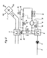
- Figur 2 eine Lüftungsanlage nach Fig. 1, wobei zur Beheizung eines Wärmepumpe vorgesehen ist, und
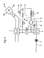
- Figur 3 eine Alternative zu Fig. 2.
- Eine Lüftungsanlage eines Gebäudes weist zur Wärmerückgewinnung einen Wärmeaustauscherapparat 1 auf, der ein Luft/Luft-Kreuzstrom- oder Kreuzgegenstrom-Wärmeaustauscher mit Zuluftlüfter und Abluftlüfter sein kann. Durch den Wärmeaustauscherapparat 1 wird Außenluft AU aus der Umgebung als Zuluft ZU den Räumen des Gebäudes zugeführt. Aus den Räumen wird Abluft AB abgeführt. Wärme der Abluft AB wird auf die Zuluft ZU übertragen. Die entwärmte Abluft wird anschließend als Fortluft nach draußen gefördert.
- Die Lüftungsanlage weist zur Beheizung der Räume einen Heizkreis 2 auf, in dem üblicherweise eine Umwälzpumpe 3 von einem nicht dargestellten Solar-, Öl- oder Gas-Heizgerät erwärmtes Wasser zu nicht dargestellten Heizkörpern fördert. Die Heizkörper können in den Räumen installiert sein und/oder im Zuluftstrom ZU angeordnet sein.
- Bei niedrigen Außentemperaturen unter ca. -3°C kann der Wärmeaustauscherapparat 1 vereisen. Um ein Vereisen, Bereifen zu vermeiden und den Wärmeaustauscherapparat 1 gegebenenfalls abzutauen, ist eine Einrichtung 4 vorgesehen.
- Die Einrichtung 4 bildet einen Abtaukreis 5, in dem ein Wärmeaustauscher 6, ein Heizregister 7 und ein ein-ausschaltbares Abtaukreisventil 8, insbesondere Magnetventil, angeordnet sind. Der Wärmeaustauscher 6 ist im Rücklauf oder Vorlauf des Heizkreises 2 angeordnet. Das Heizregister 7 liegt im Außenluftstrom AU.
- Der Abtaukreis 5 beinhaltet ein Medium, das im Wärmeaustauscher 6 bei der Temperatur des Heizkreises 2 verdampft, dann dampfförmig zum Heizregister 7 strömt, dort an die kalte Außenluft AU Wärme abgibt, dadurch kondensiert und über Schwerkraftwirkung zum Wärmeaustauscher 6 zurückfließt. Die Einrichtung arbeitet also als Wärmerohr (heat pipe). Dadurch wird aus der Wärme des Heizkreises 2 der Wärmeaustauscherapparat 1 eisfrei gehalten bzw. abgetaut.
- Der Abtaukreis 5 arbeitet auch, wenn die Umwälzpumpe 3 ausfällt, da sich auch dann aufgrund der Temperatur- und Dichteunterschiede des Wassers im Heizkreis 2 eine Strömung einstellt, aus der der Wärmeaustauscher 6 Wärme auf das Heizregister 7 übertragen kann.
- Das Abtaukreisventil 8 wird geschlossen, wenn nicht die Gefahr eines Vereisens des Wärmeaustauscherapparats 1 besteht. Das Ein- und Ausschalten kann außentemperaturabhängig erfolgen.
- Nach Figur 2 ist der Heizkreis 2 in an sich bekannter Weise von einem Verflüssiger 9 einer Wärmepumpe 10 beheizt, die einen Verdichter 11, einen Luft-Kältemittel-Verdampfer 12 und ein Expansionsventil 13 aufweist. Im Wärmepumpenkreis ist ein weiteres Ventil 14 vorgesehen.
- Der Verflüssiger 9 bildet zugleich den Wärmeaustauscher 6 des Abtaukreises 5. Das Kältemittel des Wärmepumpenkreises ist das Medium des Abtaukreises. Das Heizregister 7 ist an den Verflüssiger 9 angeschlossen.
- Beim Betrieb der Wärmepumpe 10 nach Figur 2 ist das Abtaukreisventil 8 geschlossen und das weitere Ventil 14 geöffnet. Das Heizregister 7 liegt dabei in Strömungsrichtung des Kältemittels hinter dem Verflüssiger 9 und wird vom Kältemittel erwärmt, so dass es Wärme auf die Außenluft AU überträgt. Dadurch wird der Wärmeaustauscherapparat 1 eisfrei gehalten und das Kältemittel wird unterkühlt. Dies ist in der älteren Patentanmeldung 101 03 150.5 beschrieben.
- Wird die Wärmepumpe 10 abgeschaltet, weil kein Wärmebedarf besteht, dann wird das weitere Ventil 14 geschlossen. Dieses liegt in Strömungsrichtung des Kältemittels vor dem Expansionsventil 13. Das weitere Ventil 14 kann ein Pump-down-Ventil sein. Je nach der Kältemittelfüllmenge und internen Volumina der Aggregate kann das Kältemittel über das weitere Ventil 14 von der Niederdruckseite des Wärmepumpenkreises jetzt noch auf die Hochdruckseite gepumpt werden, so dass für den Wärmerohreffekt eine ausreichende Menge von Arbeitsmedium zur Verfügung steht. Das Abtaukreisventil 8 wird geöffnet. Im Verflüssiger 9 wird nun dem Wasser des Heizkreises 2 Wärme entzogen, so dass das Kältemittel verdampft und zum Heizregister 7 strömt, dort an die Außenluft AU Wärme abgibt, kondensiert und zum Verflüssiger 9 unter Schwerkraftwirkung im Heizregister 7 kein Wärmetausch mehr stattfindet oder das Abtaukreisventil 8 geschlossen wird und die Wärmepumpe 10 wieder eingeschaltet wird.
- Das Ausführungsbeispiel nach Figur 3 entspricht dem von Figur 2, wobei jedoch das Heizregister 7 dem Verflüssiger 9 parallelgeschaltet ist. Ist das Abtaukreisventil 8 geöffnet und die Wärmepumpe 10 abgeschaltet, dann arbeitet der Abtaukreis 5 in der beschriebenen Weise. Ist die Wärmepumpe 10 in Betrieb und das Abtaukreisventil 8 geöffnet, dann wird der Verflüssiger 9 und das Heizregister 7 parallel vom Kältemittel durchströmt. Ist das Abtaukreisventil 8 geschlossen, wird nur der Verflüssiger 9 durchströmt.
- In den Figuren 2 und 3 sind zusätzlich ein Bypass 15 mit Ventil 16 zu den Ventilen 13,14 und ein Bypass 17 mit Ventil 18 zu dem Verdichter 11 gezeigt. Durch Öffnen der Bypässe 15,17 lässt sich mit denbeschriebenen Mitteln auch der Verdampfer 12 der Wärmepumpe 10 abtauen. In Figur 2 ist ergänzend ein Bypass 19 mit Ventil 20 gezeigt. Dieser wird geöffnet, wenn das Kältemittel beim Abtauen des Verdampfers 12 nicht durch das Heizregister 7 strömen soll. Damit dient der Wärmeaustauscher 6 bzw. Verflüssiger 9 sowohl dem Eisfreihalten des Wärmeaustauscherapparats 1 als auch des Verdichters 12.
Claims (12)
- Einrichtung zum Abtauen oder Eisfreihalten eines Wärmeaustauscherapparates, über den beheizbaren Räumen Außenluft zuführbar und Raumluft abführbar ist, bei der ein Wärmeaustauscher (6) und ein im Außenluftstrom (AU) des Wärmeaustauscherapparates (1) angeordnetes Heizregister (7) zu einem, ein Medium führenden Abtaukreis (5) geschaltet sind,
dadurch gekennzeichnet,
dass der Wärmeaustauscher (6) im Heizkreis (2) der Räume angeordnet ist,
wobei das Medium im Wärmeaustauscher (6) verdampft und im Heizregister (7) kondensiert. - Einrichtung nach Anspruch 1,
dadurch gekennzeichnet,
dass im Abtaukreis (5) ein ein-/ ausschaltbares Abtaukreisventil (8) angeordnet ist. - Einrichtung nach Anspruch 1 oder 2,
dadurch gekennzeichnet,
dass das Medium im Abtaukreis (5) unter Schwerkraftwirkung zirkuliert. - Einrichtung nach Anspruch 3,
dadurch gekennzeichnet,
dass das Medium derart gewählt ist, dass es bei Temperaturen unter 0°C flüssig oder gasförmig bleibt. - Einrichtung nach Anspruch 3,
dadurch gekennzeichnet,
dass das Medium ein Kältemittel ist, das bei der Vorlauftemperatur oder der Rücklauftemperatur des Heizkreises (2) verdampft. - Einrichtung nach einem der vorhergehenden Ansprüche, wobei der Heizkreis (2) von einem Verflüssiger (9) einer Wärmepumpe (10) beheizbar ist,
dadurch gekennzeichnet,
dass der Verflüssiger (9) der Wärmepumpe (10) den Wärmeaustauscher (6) des Abtaukreises (5) bildet, wobei das Medium des Abtaukreises (5) vom Kältemittel der Wärmepumpe (10) gebildet ist. - Einrichtung nach Anspruch 6,
dadurch gekennzeichnet,
dass das Heizregister (7) bei geschlossenem Abtaukreisventil (8) in Reihe zum Verflüssiger (9) der Wärmepumpe (10) liegt und dass bei geöffnetem Abtaukreisventil (8) und abgeschalteter Wärmepumpe (10) der Abtaukreis (5) wirksam ist. - Einrichtung nach Anspruch 7,
dadurch gekennzeichnet,
dass das Heizregister (7) in Strömungsrichtung des Kältemittels hinter dem Verflüssiger (9) liegt, wobei es im Betrieb der Wärmepumpe (9) das Kältemittel unterkühlt. - Einrichtung nach Anspruch 6,
dadurch gekennzeichnet,
dass das Heizregister (7) parallel zum Verflüssiger (9) der Wärmepumpe (10) geschaltet ist. - Einrichtung nach einem der vorhergehenden Ansprüche 6 bis 9,
dadurch gekennzeichnet,
dass im Wärmepumpenkreis (10) ein weiteres Ventil (14) angeordnet ist, das bei geöffnetem Abtaukreisventil (8) geschlossen ist. - Einrichtung nach Anspruch 10,
dadurch gekennzeichnet,
dass das weitere Ventil (14) mit Hilfe des Kompressors Kältemittel von der Niederdruckseite der Wärmepumpe (10) auf die Hochdruckseite der Wärmepumpe (10) gelangen lässt. - Einrichtung nach einem der vorhergehenden Ansprüche 6 bis 11,
dadurch gekennzeichnet,
dass mittels des Verflüssigers (9) des Abtaukreises (5) der Verdampfer (12) der Wärmepumpe (10) abtaubar ist.
Applications Claiming Priority (2)
| Application Number | Priority Date | Filing Date | Title |
|---|---|---|---|
| DE10215587 | 2002-04-10 | ||
| DE10215587A DE10215587B4 (de) | 2002-04-10 | 2002-04-10 | Einrichtung zum Eisfreihalten eines Wärmeaustauscherapparats |
Publications (2)
| Publication Number | Publication Date |
|---|---|
| EP1353130A1 EP1353130A1 (de) | 2003-10-15 |
| EP1353130B1 true EP1353130B1 (de) | 2006-06-28 |
Family
ID=28051224
Family Applications (1)
| Application Number | Title | Priority Date | Filing Date |
|---|---|---|---|
| EP03008249A Expired - Lifetime EP1353130B1 (de) | 2002-04-10 | 2003-04-09 | Einrichtung zum Eisfreihalten eines Wärmeaustauscherapparats |
Country Status (3)
| Country | Link |
|---|---|
| EP (1) | EP1353130B1 (de) |
| AT (1) | ATE331918T1 (de) |
| DE (2) | DE10215587B4 (de) |
Families Citing this family (3)
| Publication number | Priority date | Publication date | Assignee | Title |
|---|---|---|---|---|
| EP3255356B1 (de) * | 2016-06-08 | 2019-04-24 | Vestel Elektronik Sanayi ve Ticaret A.S. | Heizvorrichtung mit zwei kombinierten wärmeeinheiten und heizverfahren |
| CN108731292A (zh) * | 2018-07-09 | 2018-11-02 | 广东申菱环境系统股份有限公司 | 一种热虹吸式融霜双通道油气回收冷凝机组 |
| DE102020106625B4 (de) | 2020-03-11 | 2024-08-08 | Audi Aktiengesellschaft | Nachheizverfahren zum Betreiben einer Kälteanlage für ein Kraftfahrzeug, Kälteanlage und Kraftfahrzeug mit einer solchen Kälteanlage |
Family Cites Families (10)
| Publication number | Priority date | Publication date | Assignee | Title |
|---|---|---|---|---|
| JPS5818566B2 (ja) * | 1976-07-08 | 1983-04-13 | ダイキン工業株式会社 | 熱回収装置 |
| JP2726941B2 (ja) * | 1989-06-27 | 1998-03-11 | 昭和アルミニウム株式会社 | 換気用熱交換器 |
| US5189884A (en) * | 1991-05-02 | 1993-03-02 | Sami Samuel M | Passive heat pump with non-azeotropic refrigerant |
| US5325676A (en) * | 1992-08-24 | 1994-07-05 | Milton Meckler | Desiccant assisted multi-use air pre-conditioner unit with system heat recovery capability |
| DE19500527A1 (de) * | 1995-01-11 | 1996-07-18 | Kulmbacher Klimageraete | Klimagerät |
| DE19702903C2 (de) * | 1997-01-28 | 2000-08-24 | Stiebel Eltron Gmbh & Co Kg | Klimaanlage mit einer Wärmepumpe |
| DE19827511A1 (de) * | 1997-12-11 | 1999-06-24 | Fraunhofer Ges Forschung | Vorrichtung und Verfahren zur Lüftung und Wärmeenergieversorgung für Niedrig-Energie-Gebäude oder Passivhäuser |
| DE10007077A1 (de) * | 1999-02-17 | 2000-08-31 | Walter Schoepf | Heizungs- und Lüftungssystem für Wohnräume |
| DE19913861C1 (de) * | 1999-03-26 | 2000-07-06 | Stiebel Eltron Gmbh & Co Kg | Klimaanlage mit einer Wärmepumpe |
| DE20122902U1 (de) * | 2001-01-24 | 2009-09-24 | Stiebel Eltron Gmbh & Co. Kg | Lüftungsanlage |
-
2002
- 2002-04-10 DE DE10215587A patent/DE10215587B4/de not_active Expired - Lifetime
-
2003
- 2003-04-09 EP EP03008249A patent/EP1353130B1/de not_active Expired - Lifetime
- 2003-04-09 AT AT03008249T patent/ATE331918T1/de active
- 2003-04-09 DE DE50304018T patent/DE50304018D1/de not_active Expired - Lifetime
Also Published As
| Publication number | Publication date |
|---|---|
| DE50304018D1 (de) | 2006-08-10 |
| DE10215587A1 (de) | 2003-11-06 |
| ATE331918T1 (de) | 2006-07-15 |
| EP1353130A1 (de) | 2003-10-15 |
| DE10215587B4 (de) | 2006-03-23 |
Similar Documents
| Publication | Publication Date | Title |
|---|---|---|
| EP1397265B1 (de) | Klimaanlage | |
| EP0945291B1 (de) | Vorrichtung und Verfahren zum Heizen und Kühlen eines Nutzraumes eines Kraftfahrzeuges | |
| EP2620715B1 (de) | Verfahren zum Betrieb eines Lüftungsheizgerätes und Lüftungsheizgerät | |
| EP2821727B1 (de) | Verfahren zum Betrieb eines Lüftungsheizgerätes und Lüftungsheizgerät | |
| EP2093083A2 (de) | Klimaanlage | |
| DE19702903A1 (de) | Klimaanlage mit einer Wärmepumpe | |
| DE112019006489T5 (de) | Fahrzeugluftkonditioniereinrichtung | |
| DE102017118425A1 (de) | Kreislaufsystem für ein Fahrzeug und Verfahren dazu | |
| EP1876402A2 (de) | Wärmepumpe mit einer Temperiereinrichtung | |
| DE202009006988U1 (de) | Warmwasserversorgungsanlage mit einem Warmwasserspeicher | |
| DE3301303C2 (de) | ||
| DE112016003261T5 (de) | Klimaanlagengerät für Fahrzeuge | |
| WO2010043399A2 (de) | Kühlsystem | |
| AT412911B (de) | Vorrichtung zum erwärmen eines wärmeträgers | |
| KR100734904B1 (ko) | 냉난방 겸용 히트펌프 시스템 | |
| DE10215587B4 (de) | Einrichtung zum Eisfreihalten eines Wärmeaustauscherapparats | |
| KR200411589Y1 (ko) | 냉난방 겸용 히트펌프 시스템 | |
| EP3314178A1 (de) | Einrichtung und verfahren zum enteisen eines wärmetauschers im verdampferbetrieb einer kälteanlage sowie fahrzeug mit einer solchen einrichtung | |
| DE2954402C2 (de) | ||
| DE10313097B4 (de) | Wärmepumpenanlage mit einer Wärmepumpe und einem Wärmequellenkreis | |
| DE602004008761T2 (de) | Kühlsystem und verfahren zum betrieb eines solchen systems | |
| EP3885661A1 (de) | Verfahren zum betreiben eines lüftungsheizsystems und lüftungsheizsystem | |
| DE10103150B4 (de) | Lüftungsanlage | |
| CH696410A5 (de) | Verfahren und Einrichtung zum Abtauen des Verdampfers einer Wärmepumpe. | |
| DE102023004618A1 (de) | Kompressionskältemaschine mit umschaltbaren Wärmetauschern und optionaler Füllmengenregulierung |
Legal Events
| Date | Code | Title | Description |
|---|---|---|---|
| PUAI | Public reference made under article 153(3) epc to a published international application that has entered the european phase |
Free format text: ORIGINAL CODE: 0009012 |
|
| AK | Designated contracting states |
Kind code of ref document: A1 Designated state(s): AT BE BG CH CY CZ DE DK EE ES FI FR GB GR HU IE IT LI LU MC NL PT RO SE SI SK TR |
|
| AX | Request for extension of the european patent |
Extension state: AL LT LV MK |
|
| 17P | Request for examination filed |
Effective date: 20031017 |
|
| AKX | Designation fees paid |
Designated state(s): AT BE BG CH CY CZ DE DK EE ES FI FR GB GR HU IE IT LI LU MC NL PT RO SE SI SK TR |
|
| 17Q | First examination report despatched |
Effective date: 20041012 |
|
| GRAP | Despatch of communication of intention to grant a patent |
Free format text: ORIGINAL CODE: EPIDOSNIGR1 |
|
| GRAS | Grant fee paid |
Free format text: ORIGINAL CODE: EPIDOSNIGR3 |
|
| GRAA | (expected) grant |
Free format text: ORIGINAL CODE: 0009210 |
|
| AK | Designated contracting states |
Kind code of ref document: B1 Designated state(s): AT BE BG CH CY CZ DE DK EE ES FI FR GB GR HU IE IT LI LU MC NL PT RO SE SI SK TR |
|
| PG25 | Lapsed in a contracting state [announced via postgrant information from national office to epo] |
Ref country code: IE Free format text: LAPSE BECAUSE OF FAILURE TO SUBMIT A TRANSLATION OF THE DESCRIPTION OR TO PAY THE FEE WITHIN THE PRESCRIBED TIME-LIMIT Effective date: 20060628 Ref country code: RO Free format text: LAPSE BECAUSE OF FAILURE TO SUBMIT A TRANSLATION OF THE DESCRIPTION OR TO PAY THE FEE WITHIN THE PRESCRIBED TIME-LIMIT Effective date: 20060628 Ref country code: IT Free format text: LAPSE BECAUSE OF FAILURE TO SUBMIT A TRANSLATION OF THE DESCRIPTION OR TO PAY THE FEE WITHIN THE PRESCRIBED TIME-LIMIT;WARNING: LAPSES OF ITALIAN PATENTS WITH EFFECTIVE DATE BEFORE 2007 MAY HAVE OCCURRED AT ANY TIME BEFORE 2007. THE CORRECT EFFECTIVE DATE MAY BE DIFFERENT FROM THE ONE RECORDED. Effective date: 20060628 Ref country code: NL Free format text: LAPSE BECAUSE OF FAILURE TO SUBMIT A TRANSLATION OF THE DESCRIPTION OR TO PAY THE FEE WITHIN THE PRESCRIBED TIME-LIMIT Effective date: 20060628 Ref country code: SI Free format text: LAPSE BECAUSE OF FAILURE TO SUBMIT A TRANSLATION OF THE DESCRIPTION OR TO PAY THE FEE WITHIN THE PRESCRIBED TIME-LIMIT Effective date: 20060628 Ref country code: CZ Free format text: LAPSE BECAUSE OF FAILURE TO SUBMIT A TRANSLATION OF THE DESCRIPTION OR TO PAY THE FEE WITHIN THE PRESCRIBED TIME-LIMIT Effective date: 20060628 Ref country code: SK Free format text: LAPSE BECAUSE OF FAILURE TO SUBMIT A TRANSLATION OF THE DESCRIPTION OR TO PAY THE FEE WITHIN THE PRESCRIBED TIME-LIMIT Effective date: 20060628 Ref country code: FI Free format text: LAPSE BECAUSE OF FAILURE TO SUBMIT A TRANSLATION OF THE DESCRIPTION OR TO PAY THE FEE WITHIN THE PRESCRIBED TIME-LIMIT Effective date: 20060628 |
|
| REG | Reference to a national code |
Ref country code: GB Ref legal event code: FG4D Free format text: NOT ENGLISH |
|
| REG | Reference to a national code |
Ref country code: CH Ref legal event code: EP |
|
| REG | Reference to a national code |
Ref country code: IE Ref legal event code: FG4D Free format text: LANGUAGE OF EP DOCUMENT: GERMAN |
|
| REF | Corresponds to: |
Ref document number: 50304018 Country of ref document: DE Date of ref document: 20060810 Kind code of ref document: P |
|
| REG | Reference to a national code |
Ref country code: SE Ref legal event code: TRGR |
|
| REG | Reference to a national code |
Ref country code: CH Ref legal event code: NV Representative=s name: BRAUNPAT BRAUN EDER AG |
|
| PG25 | Lapsed in a contracting state [announced via postgrant information from national office to epo] |
Ref country code: DK Free format text: LAPSE BECAUSE OF FAILURE TO SUBMIT A TRANSLATION OF THE DESCRIPTION OR TO PAY THE FEE WITHIN THE PRESCRIBED TIME-LIMIT Effective date: 20060928 |
|
| PG25 | Lapsed in a contracting state [announced via postgrant information from national office to epo] |
Ref country code: ES Free format text: LAPSE BECAUSE OF FAILURE TO SUBMIT A TRANSLATION OF THE DESCRIPTION OR TO PAY THE FEE WITHIN THE PRESCRIBED TIME-LIMIT Effective date: 20061009 |
|
| GBT | Gb: translation of ep patent filed (gb section 77(6)(a)/1977) |
Effective date: 20060919 |
|
| PG25 | Lapsed in a contracting state [announced via postgrant information from national office to epo] |
Ref country code: PT Free format text: LAPSE BECAUSE OF FAILURE TO SUBMIT A TRANSLATION OF THE DESCRIPTION OR TO PAY THE FEE WITHIN THE PRESCRIBED TIME-LIMIT Effective date: 20061128 |
|
| NLV1 | Nl: lapsed or annulled due to failure to fulfill the requirements of art. 29p and 29m of the patents act | ||
| ET | Fr: translation filed | ||
| REG | Reference to a national code |
Ref country code: IE Ref legal event code: FD4D |
|
| PLBE | No opposition filed within time limit |
Free format text: ORIGINAL CODE: 0009261 |
|
| STAA | Information on the status of an ep patent application or granted ep patent |
Free format text: STATUS: NO OPPOSITION FILED WITHIN TIME LIMIT |
|
| 26N | No opposition filed |
Effective date: 20070329 |
|
| PG25 | Lapsed in a contracting state [announced via postgrant information from national office to epo] |
Ref country code: GR Free format text: LAPSE BECAUSE OF FAILURE TO SUBMIT A TRANSLATION OF THE DESCRIPTION OR TO PAY THE FEE WITHIN THE PRESCRIBED TIME-LIMIT Effective date: 20060929 |
|
| PG25 | Lapsed in a contracting state [announced via postgrant information from national office to epo] |
Ref country code: BG Free format text: LAPSE BECAUSE OF FAILURE TO SUBMIT A TRANSLATION OF THE DESCRIPTION OR TO PAY THE FEE WITHIN THE PRESCRIBED TIME-LIMIT Effective date: 20060928 |
|
| PG25 | Lapsed in a contracting state [announced via postgrant information from national office to epo] |
Ref country code: EE Free format text: LAPSE BECAUSE OF FAILURE TO SUBMIT A TRANSLATION OF THE DESCRIPTION OR TO PAY THE FEE WITHIN THE PRESCRIBED TIME-LIMIT Effective date: 20060628 |
|
| PG25 | Lapsed in a contracting state [announced via postgrant information from national office to epo] |
Ref country code: MC Free format text: LAPSE BECAUSE OF NON-PAYMENT OF DUE FEES Effective date: 20070430 |
|
| PG25 | Lapsed in a contracting state [announced via postgrant information from national office to epo] |
Ref country code: CY Free format text: LAPSE BECAUSE OF FAILURE TO SUBMIT A TRANSLATION OF THE DESCRIPTION OR TO PAY THE FEE WITHIN THE PRESCRIBED TIME-LIMIT Effective date: 20060628 Ref country code: LU Free format text: LAPSE BECAUSE OF NON-PAYMENT OF DUE FEES Effective date: 20070409 |
|
| PG25 | Lapsed in a contracting state [announced via postgrant information from national office to epo] |
Ref country code: HU Free format text: LAPSE BECAUSE OF FAILURE TO SUBMIT A TRANSLATION OF THE DESCRIPTION OR TO PAY THE FEE WITHIN THE PRESCRIBED TIME-LIMIT Effective date: 20061229 Ref country code: TR Free format text: LAPSE BECAUSE OF FAILURE TO SUBMIT A TRANSLATION OF THE DESCRIPTION OR TO PAY THE FEE WITHIN THE PRESCRIBED TIME-LIMIT Effective date: 20060628 |
|
| PGFP | Annual fee paid to national office [announced via postgrant information from national office to epo] |
Ref country code: IT Payment date: 20140428 Year of fee payment: 12 |
|
| PGFP | Annual fee paid to national office [announced via postgrant information from national office to epo] |
Ref country code: BE Payment date: 20140418 Year of fee payment: 12 |
|
| PG25 | Lapsed in a contracting state [announced via postgrant information from national office to epo] |
Ref country code: IT Free format text: LAPSE BECAUSE OF NON-PAYMENT OF DUE FEES Effective date: 20150409 |
|
| REG | Reference to a national code |
Ref country code: FR Ref legal event code: PLFP Year of fee payment: 14 |
|
| REG | Reference to a national code |
Ref country code: FR Ref legal event code: PLFP Year of fee payment: 15 |
|
| PG25 | Lapsed in a contracting state [announced via postgrant information from national office to epo] |
Ref country code: BE Free format text: LAPSE BECAUSE OF NON-PAYMENT OF DUE FEES Effective date: 20150430 |
|
| REG | Reference to a national code |
Ref country code: FR Ref legal event code: PLFP Year of fee payment: 16 |
|
| REG | Reference to a national code |
Ref country code: CH Ref legal event code: PCAR Free format text: NEW ADDRESS: HOLEESTRASSE 87, 4054 BASEL (CH) |
|
| PGFP | Annual fee paid to national office [announced via postgrant information from national office to epo] |
Ref country code: SE Payment date: 20220421 Year of fee payment: 20 Ref country code: GB Payment date: 20220420 Year of fee payment: 20 Ref country code: FR Payment date: 20220420 Year of fee payment: 20 Ref country code: DE Payment date: 20220420 Year of fee payment: 20 |
|
| PGFP | Annual fee paid to national office [announced via postgrant information from national office to epo] |
Ref country code: CH Payment date: 20220421 Year of fee payment: 20 Ref country code: AT Payment date: 20220421 Year of fee payment: 20 |
|
| REG | Reference to a national code |
Ref country code: DE Ref legal event code: R071 Ref document number: 50304018 Country of ref document: DE |
|
| REG | Reference to a national code |
Ref country code: CH Ref legal event code: PL |
|
| REG | Reference to a national code |
Ref country code: GB Ref legal event code: PE20 Expiry date: 20230408 |
|
| REG | Reference to a national code |
Ref country code: AT Ref legal event code: MK07 Ref document number: 331918 Country of ref document: AT Kind code of ref document: T Effective date: 20230409 |
|
| REG | Reference to a national code |
Ref country code: SE Ref legal event code: EUG |
|
| PG25 | Lapsed in a contracting state [announced via postgrant information from national office to epo] |
Ref country code: GB Free format text: LAPSE BECAUSE OF EXPIRATION OF PROTECTION Effective date: 20230408 |