EP1353109A2 - Kupplungsteil einer Druckmittel-Steckkupplung - Google Patents
Kupplungsteil einer Druckmittel-Steckkupplung Download PDFInfo
- Publication number
- EP1353109A2 EP1353109A2 EP03007898A EP03007898A EP1353109A2 EP 1353109 A2 EP1353109 A2 EP 1353109A2 EP 03007898 A EP03007898 A EP 03007898A EP 03007898 A EP03007898 A EP 03007898A EP 1353109 A2 EP1353109 A2 EP 1353109A2
- Authority
- EP
- European Patent Office
- Prior art keywords
- valve
- coupling
- coupling part
- pressure relief
- part according
- Prior art date
- Legal status (The legal status is an assumption and is not a legal conclusion. Google has not performed a legal analysis and makes no representation as to the accuracy of the status listed.)
- Granted
Links
- 238000010168 coupling process Methods 0.000 title claims abstract description 70
- 230000008878 coupling Effects 0.000 title claims abstract description 69
- 238000005859 coupling reaction Methods 0.000 title claims abstract description 69
- 239000012530 fluid Substances 0.000 title description 2
- 239000002184 metal Substances 0.000 claims abstract description 5
- 238000007789 sealing Methods 0.000 claims abstract description 4
- 230000007935 neutral effect Effects 0.000 claims description 5
- 230000005540 biological transmission Effects 0.000 claims description 2
- 239000013013 elastic material Substances 0.000 claims description 2
- 238000006073 displacement reaction Methods 0.000 description 2
- 230000003628 erosive effect Effects 0.000 description 2
- 238000000034 method Methods 0.000 description 2
- 230000036316 preload Effects 0.000 description 2
- 238000009472 formulation Methods 0.000 description 1
- 238000003780 insertion Methods 0.000 description 1
- 230000037431 insertion Effects 0.000 description 1
- 239000000203 mixture Substances 0.000 description 1
Images


Classifications
-
- F—MECHANICAL ENGINEERING; LIGHTING; HEATING; WEAPONS; BLASTING
- F16—ENGINEERING ELEMENTS AND UNITS; GENERAL MEASURES FOR PRODUCING AND MAINTAINING EFFECTIVE FUNCTIONING OF MACHINES OR INSTALLATIONS; THERMAL INSULATION IN GENERAL
- F16L—PIPES; JOINTS OR FITTINGS FOR PIPES; SUPPORTS FOR PIPES, CABLES OR PROTECTIVE TUBING; MEANS FOR THERMAL INSULATION IN GENERAL
- F16L37/00—Couplings of the quick-acting type
- F16L37/28—Couplings of the quick-acting type with fluid cut-off means
- F16L37/30—Couplings of the quick-acting type with fluid cut-off means with fluid cut-off means in each of two pipe-end fittings
- F16L37/32—Couplings of the quick-acting type with fluid cut-off means with fluid cut-off means in each of two pipe-end fittings at least one of two lift valves being opened automatically when the coupling is applied
-
- F—MECHANICAL ENGINEERING; LIGHTING; HEATING; WEAPONS; BLASTING
- F16—ENGINEERING ELEMENTS AND UNITS; GENERAL MEASURES FOR PRODUCING AND MAINTAINING EFFECTIVE FUNCTIONING OF MACHINES OR INSTALLATIONS; THERMAL INSULATION IN GENERAL
- F16L—PIPES; JOINTS OR FITTINGS FOR PIPES; SUPPORTS FOR PIPES, CABLES OR PROTECTIVE TUBING; MEANS FOR THERMAL INSULATION IN GENERAL
- F16L37/00—Couplings of the quick-acting type
- F16L37/22—Couplings of the quick-acting type in which the connection is maintained by means of balls, rollers or helical springs under radial pressure between the parts
- F16L37/23—Couplings of the quick-acting type in which the connection is maintained by means of balls, rollers or helical springs under radial pressure between the parts by means of balls
Definitions
- the present invention relates to a coupling part one of two which can be plugged together and which have mutually opening main valves Coupling parts existing pressure medium plug-in coupling, in particular Coupling sleeve for the socket of a coupling plug, with a Pressure relief device that both engages and disengages under internal residual pressure of the pressure medium and at least one automatically each briefly opening and thereby pressure medium when engaging and disengaging Has pressure reduction to the outside relieving pressure relief valve.
- Such plug-in couplings serve in particular as quick couplings for Hydraulic lines of hydraulic pressure units.
- Locking means for releasably locking the coupling parts in the inserted Coupling position provided.
- Ball detent the coupling sleeve in the area of a receiving opening Scope distributed balls are arranged, which in the inserted state of the Areas of the coupling plug engage radially in a plug ring groove.
- the balls sit radially movable in openings of an inner body of the coupling sleeve, which has an outer sleeve in this area, which is in a first relative position the balls are locked from the outside against a radial release movement and in a second, axially displaced relative spring force the balls for a Release movement releases.
- an internal residual pressure of the pressure medium For example, up to 200 bar can be so high that coupling and uncoupling is not is easily possible. When engaging this is because the main valve cannot be opened against the existing residual pressure.
- disengaging the residual pressure acts on the locking means in such a way that it engages with high force are practically locked against unlocking, so they cannot be released manually.
- the pressure relief valve executed in the manner of an axial slide valve, wherein by axial control movements of the inner base body, a valve slide axially is moved relative to at least one radial flow opening.
- a pressure relief in both directions that means both when engaging and also possible when disengaging.
- some of them have to be very low high residual pressure soft seals are run over due to high pressure Flow rates of the flowing pressure medium a very high Wear caused by so-called erosion phenomena. this leads to a high susceptibility to failure or a short shelf life, so that the known coupling part is very maintenance-intensive.
- the present invention has for its object a coupling part to create mentioned type, which with low coupling forces both a coupling as well as disengaging in each case despite a high residual operating pressure of in particular up to at least 250 bar with little wear and long durability also possible across numerous coupling processes.
- the pressure relief valve as Metallic seat valve with a metallic valve element and a metallic valve seat is formed, the valve element with respect to its Closing and opening direction is arranged transversely to a coupling longitudinal axis.
- the pressure relief valve as desired open by a control movement in both axial directions.
- This can be a Metallic seat valve for pressure relief both when engaging and when Uncoupling are used, which ensures high durability because the metallic valve parts against flow-related erosion phenomena are resistant.
- the pressure medium plug-in coupling shown in the drawing is a quick release coupling with a known ball lock formed and consists of two coupling parts, namely a coupling sleeve 2 and a coupling plug 4.
- the coupling plug 4 is in some areas Insert opening of the coupling sleeve 2 insertable and shown in Fig. 1 Coupling position releasably lockable by locking means 6.
- the locking means 6 is a known one Locking ball-lock. The details of this interlock are state of the art and therefore need no further explanation.
- Each coupling part 2, 4 has an inner main flow channel 8 and 10, respectively each automatically by a main valve 12 or 14 in the uncoupled state is lockable.
- the two main valves 12, 14 are each other arranged opposite to each other by plug-in coupling Open the front system (see Fig. 1, 3 and 5).
- the coupling sleeve 2 has a Pressure relief device 16, but in principle could also - alternatively or additionally - the coupling plug 4 with such a pressure relief device be equipped.
- the pressure relief device 16 enables both Engaging and disengaging under an internal residual pressure of the pressure medium and has at least one automatically for a short time each time it is engaged and disengaged opening and thereby pressure medium for lowering pressure to the outside, in particular in a pressure relief valve 18 draining a collecting container (tank).
- the Pressure relief device 16 acts with an inner coupling base body 20 together in an outer clutch housing 22 from a middle Neutral position ( Figures 1 and 2) axially against spring force in both directions is displaceable relative to the clutch housing 22, namely when coupling into a Engaging position ( Figures 3 and 4) or when disengaging - at times together with a locking sleeve 23 of the locking means 6 - in a disengaging position (FIGS. 5 and 6).
- the shifting movements also act as axial control movements to open on the pressure relief valve 18 until after a corresponding pressure drop, the base body 20 due to spring force automatically moves back to the neutral position, causing the pressure relief valve 18 closes again.
- the base body 20 is essentially sleeve-shaped and encloses at its front end the insertion opening for the coupling plug 4. At its at the other end, the base body 20 has a closure element 24, in front of which Cross openings 26 branches off the flow channel 8.
- the closure element 24 separates so the main flow channel 8 from a relief chamber 28 that at least a relief channel (not recognizable in the interfaces) to the outside leads in particular to a collecting container (tank). It is Pressure relief valve 18 in a passage between the main flow channel 8 and the relief chamber 28.
- valve element 30 is according to the invention with respect to it Closing and opening direction (chain line 34) transversely, in particular radially, d. H. arranged perpendicular to a coupling longitudinal axis 36.
- chain line 34 transversely, in particular radially, d. H. arranged perpendicular to a coupling longitudinal axis 36.
- a control element 38 in particular in Form of an axial, central pin is arranged stationary.
- Pressure relief valve 18 in the region of the closure element 24 of the displaceable Base body 20 is arranged, it moves together with the base body 20th relative to the stationary control element 38.
- the control element 38 has a Control surface 40, the cam-like against an intermediate element 42 against Valve element 30 acts.
- the control surface 40 is preferably formed by an annular groove Recess 44 formed on the outer circumference of the pin-shaped control element 38, the recess 44 two oppositely inclined, in particular flat conical Has flank surfaces 44a, 44b.
- both the valve element 30 and the intermediate element 42 are each formed by a ball.
- the ball forming the intermediate element 42 is with a compared with the smaller diameter ball forming the valve element 30 and with a sufficient for a fluid passage in a radial, itself valve channel 46 adjoining valve seat 32.
- This valve channel 46 opens into an axial drain channel 48 leading to the relief chamber 28 extends the control element 38 with one for the pressure medium passage sufficient play in or through the drain channel 48.
- the valve element 30 is expediently provided with a spring-loaded preload.
- the valve element 30 sits in one radial bore of a bush-like, arranged in the closure element 24 Carrier element 50.
- the carrier element 50 is in the region of the bore of enclosed a ring 52 made of rubber-elastic material that the ring 52 the Valve element 30 is subjected to the radially inward biasing force.
- other types of spring elements for generating the Preload possible.
- the Pressure relief device 16 at least two of the same type, with the same Control element 38 has cooperating pressure relief valves 18, which then are arranged in particular on diametrically opposite sides. Therefore in the half-sectional view only one of the pressure relief valves 18 can be seen.
- Another pressure relief valve would be of the same type and to the coupling longitudinal axis 36 symmetrical.
- the invention is not limited to that shown and described Embodiments limited, but also includes all within the meaning of the invention equivalent designs. Furthermore, the invention is not yet open the combination of features defined in claim 1 limits, but can also through any other combination of certain characteristics of all overall disclosed individual features can be defined. This means that basically omitted practically every single feature of claim 1 or by at least one individual feature disclosed elsewhere in the application can be replaced. In this respect, claim 1 is only a first To understand formulation attempt for an invention.
Landscapes
- Engineering & Computer Science (AREA)
- General Engineering & Computer Science (AREA)
- Mechanical Engineering (AREA)
- Safety Valves (AREA)
- Quick-Acting Or Multi-Walled Pipe Joints (AREA)
- Pens And Brushes (AREA)
- External Artificial Organs (AREA)
- Lift Valve (AREA)
Abstract
Description
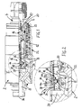
- Fig. 1
- eine halbgeschnittene Seitenansicht einer Steckkupplung mit einer erfindungsgemäßen Kupplungsmuffe und einem eingesteckten und verriegelten Kupplungsstecker mit geöffneten Hauptventilen in einer geschlossenen Neutralstellung der Druckentlastungseinrichtung,
- Fig.2
- eine vergrößerte Darstellung des Bereichs II gemäß Fig. 1 zur Erläuterung des Druckentlastungsventils,
- Fig. 3
- eine Darstellung analog zu Fig. 1, jedoch zur Erläuterung des Vorgangs beim Einkuppeln in einer ersten Öffnungsstellung der Druckentlastungseinrichtung,
- Fig. 4
- eine zu Fig. 2 analoge Darstellung des Bereichs IV in Fig. 3,
- Fig.5
- eine Darstellung analog zu Fig. 1 bzw. 3 zur Erläuterung des Auskuppelvorganges in einer zweiten Öffnungsstellung der Druckentlastungseinrichtung und
- Fig. 6
- eine Vergrößerung des Bereichs VI in Fig. 5.
Claims (12)
- Kupplungsteil (2) einer aus zwei zusammensteckbaren und sich dabei gegenseitig öffnende Hauptventile (12, 14) aufweisenden Kupplungsteilen (2, 4) bestehenden Druckmittel-Steckkupplung, insbesondere Kupplungsmuffe (2) zur Steckaufnahme eines Kupplungssteckers (4), mit einer Druckentlastungseinrichtung (16), die sowohl ein Einkuppeln als auch ein Auskuppeln unter innerem Druck des Druckmittels ermöglicht und dazu mindestens ein selbsttätig jeweils beim Ein- und Auskuppeln kurzzeitig öffnendes und dadurch Druckmittel zur Druckabsenkung nach außen ablassendes Druckentlastungsventil (18) aufweist,
dadurch gekennzeichnet, dass das Druckentlastungsventil (18) als metallisch dichtendes Sitzventil mit einem metallischen Ventilelement (30) und einem metallischen Ventilsitz (32) ausgebildet ist, wobei das Ventilelement (30) bezüglich seiner Schließ- und Öffnungsrichtung (34) quer zu einer Kupplungslängsachse (36) angeordnet ist. - Kupplungsteil nach Anspruch 1,
dadurch gekennzeichnet, dassdie Druckentlastungseinrichtung (16) mit einem inneren Kupplungs-Grundkörper (20) zusammenwirkt, der in einem äußeren Kupplungsgehäuse (22) derart aus einer mittleren Neutralstellung (Fig. 12) jeweils gegen Federkraft axial in beiden Richtungen relativ zum Kupplungsgehäuse (22) bewegbar ist, und zwar beim Einkuppeln in eine Einkuppelstellung (Fig. 3, 4) bzw. beim Auskuppeln in eine Auskuppelstellung (Fig. 5, 6), dass jeweils durch diese axiale Steuerbewegung das Druckentlastungsventil (18) zum Öffnen betätigt wird. - Kupplungsteil nach Anspruch 1 oder 2,
dadurch gekennzeichnet, dass die axiale Grundkörper-Steuerbewegung über Übertragungselemente in eine im Wesentlichen radiale Öffnungsbewegung des Ventilelementes (30) umgesetzt wird. - Kupplungsteil nach Anspruch 3,
dadurch gekennzeichnet, dass das Druckentlastungsventil (18) gemeinsam mit dem Grundkörper (20) relativ zu einem innerhalb des Kupplungsgehäuses (22) ortsfest angeordneten Steuerelement (38) beweglich ist, wobei das Steuerelement (38) radial mit einer Steuerfläche (40) über ein Zwischenelement (42) gegen das Ventilelement (30) wirkt. - Kupplungsteil nach einem der Ansprüche 1 bis 4,
dadurch gekennzeichnet, dass das Ventilelement (30) in einer Schließstellung radial nach innen gegen den Ventilsitz (32) wirkt und radial nach außen in eine Öffnungsstellung bewegbar ist. - Kupplungsteil nach Anspruch 4 oder 5,
dadurch gekennzeichnet, dass das Steuerelement (38) durch einen axialen, insbesondere zentrischen Stift gebildet ist, der als Steuerfläche (40) auf seinem Außenumfang eine ringnutartige Vertiefung (44) mit zwei entgegengesetzt schrägen, insbesondere flach konischen Flankenflächen (44a, 44b) aufweist. - Kupplungsteil nach einem der Ansprüche 1 bis 6,
dadurch gekennzeichnet, dass das Ventilelement(30)durch eine Kugel gebildet ist. - Kupplungsteil nach einem der Ansprüche 4 bis 7,
dadurch gekennzeichnet, dass das Zwischenelement (42) durch eine Kugel gebildet ist. - Kupplungsteil nach Anspruch 7 und 8,
dadurch gekennzeichnet, dass die das Zwischenelement (42) bildende Kugel mit einem gegenüber der das Ventilelement (30) bildenden Kugel kleineren Durchmesser und mit einem für einen Druckmitteldurchlaß ausreichenden Spiel in einem radialen, sich an den Ventilsitz (32) anschließenden Ventilkanal (46) angeordnet ist, der in einen axialen Abflußkanal (48) mündet, wobei sich das Steuerelement (38) mit einem für den Druckmitteldurchlaß ausreichenden Spiel in den Abflußkanal (48) erstreckt. - Kupplungsteil nach einem der Ansprüche 1 bis 9,
dadurch gekennzeichnet, dass das Ventilelement (30) in Schließrichtung mit einer federelastischen Vorspannkraft beaufschlagt ist. - Kupplungsteil nach Anspruch 10,
dadurch gekennzeichnet, dass das Ventilelement (30) in einer radialen Bohrung eines Trägerelementes (50) sitzt, wobei das Trägerelement (50) im Bereich der Bohrung von einem Ring (52) aus gummielastischem Material so umschlossen ist, dass der Ring (52) das Ventilelement (30) mit der Vorspannkraft beaufschlagt. - Kupplungsteil nach einem der Ansprüche 1 bis 11,
dadurch gekennzeichnet, dass die Druckentlastungseinrichtung (16) mindestens zwei gleichartige, mit dem gleichen Steuerelement (38) zusammenwirkende Druckentlastungsventile (18) aufweist.
Applications Claiming Priority (2)
| Application Number | Priority Date | Filing Date | Title |
|---|---|---|---|
| DE20205441U DE20205441U1 (de) | 2002-04-08 | 2002-04-08 | Kupplungsteil einer Druckmittel-Steckkupplung |
| DE20205441U | 2002-04-08 |
Publications (3)
| Publication Number | Publication Date |
|---|---|
| EP1353109A2 true EP1353109A2 (de) | 2003-10-15 |
| EP1353109A3 EP1353109A3 (de) | 2003-12-03 |
| EP1353109B1 EP1353109B1 (de) | 2010-08-18 |
Family
ID=7969803
Family Applications (1)
| Application Number | Title | Priority Date | Filing Date |
|---|---|---|---|
| EP03007898A Expired - Lifetime EP1353109B1 (de) | 2002-04-08 | 2003-04-07 | Kupplungsteil einer Druckmittel-Steckkupplung |
Country Status (3)
| Country | Link |
|---|---|
| EP (1) | EP1353109B1 (de) |
| AT (1) | ATE478298T1 (de) |
| DE (2) | DE20205441U1 (de) |
Cited By (2)
| Publication number | Priority date | Publication date | Assignee | Title |
|---|---|---|---|---|
| EP1707863A1 (de) * | 2005-03-30 | 2006-10-04 | Voswinkel KG | Kupplungsteil einer Druckmittel-Steckkupplung |
| US10094502B2 (en) | 2015-12-23 | 2018-10-09 | Staubli Faverges | Male or female quick coupling element and quick coupling including such an element |
Families Citing this family (1)
| Publication number | Priority date | Publication date | Assignee | Title |
|---|---|---|---|---|
| DE102007008143B4 (de) * | 2006-03-02 | 2015-01-29 | Voswinkel Entwicklungs- Und Verwaltungs-Gmbh & Co. Kg | Kupplungsteil einer Hydraulik-Steckkupplung |
Citations (1)
| Publication number | Priority date | Publication date | Assignee | Title |
|---|---|---|---|---|
| US5918633A (en) | 1997-02-10 | 1999-07-06 | Snap-Tite Technologies, Inc. | Farm coupling |
Family Cites Families (1)
| Publication number | Priority date | Publication date | Assignee | Title |
|---|---|---|---|---|
| DE3728577A1 (de) * | 1987-08-27 | 1989-03-16 | Aeroquip Gmbh | Schnellverschlusskupplung fuer insbesondere hydraulikleitungen |
-
2002
- 2002-04-08 DE DE20205441U patent/DE20205441U1/de not_active Expired - Lifetime
-
2003
- 2003-04-07 AT AT03007898T patent/ATE478298T1/de active
- 2003-04-07 EP EP03007898A patent/EP1353109B1/de not_active Expired - Lifetime
- 2003-04-07 DE DE50312987T patent/DE50312987D1/de not_active Expired - Lifetime
Patent Citations (1)
| Publication number | Priority date | Publication date | Assignee | Title |
|---|---|---|---|---|
| US5918633A (en) | 1997-02-10 | 1999-07-06 | Snap-Tite Technologies, Inc. | Farm coupling |
Cited By (2)
| Publication number | Priority date | Publication date | Assignee | Title |
|---|---|---|---|---|
| EP1707863A1 (de) * | 2005-03-30 | 2006-10-04 | Voswinkel KG | Kupplungsteil einer Druckmittel-Steckkupplung |
| US10094502B2 (en) | 2015-12-23 | 2018-10-09 | Staubli Faverges | Male or female quick coupling element and quick coupling including such an element |
Also Published As
| Publication number | Publication date |
|---|---|
| EP1353109A3 (de) | 2003-12-03 |
| ATE478298T1 (de) | 2010-09-15 |
| DE20205441U1 (de) | 2002-06-20 |
| EP1353109B1 (de) | 2010-08-18 |
| DE50312987D1 (de) | 2010-09-30 |
Similar Documents
| Publication | Publication Date | Title |
|---|---|---|
| DE69003467T2 (de) | Schnellvervindungs- und Schnellöse-Kupplung. | |
| DE19882860B4 (de) | Hochdruck-Fluidleitungsverbinder | |
| EP0381069B1 (de) | Kupplungsmuffe für hydraulische Leitungsverbindung | |
| EP0034312B1 (de) | Auch unter Druck kuppelbare Schnellverschlusskupplung | |
| EP0013393A1 (de) | Rohrleitungskupplung | |
| EP0038056A2 (de) | Schnellkupplung für Schläuche o.dgl. | |
| DE4000210A1 (de) | Kupplung fuer eine kaelteanlage | |
| DE3804077A1 (de) | Druckentlastete hydraulische kupplung | |
| DE4140995A1 (de) | Schnelltrennkupplung | |
| DE3433787A1 (de) | Druckmindervorrichtung fuer eine rohr- oder schlauchleitungs-schnellkupplung | |
| DE102009024899B4 (de) | Hydraulische Kupplung mit Tellerventil mit glatter Bohrung | |
| DE3036141A1 (de) | Anschlussverbindungsstueck zum anschliessen von leitungen | |
| DE1959737A1 (de) | Unter hohem Druck verbindbare Kupplung fuer Fluessigkeitsleitungen | |
| DE10147657B4 (de) | Hydraulische Unterwasserkupplung mit innerem Schutz für Strömungsöffnung | |
| EP1066460A2 (de) | Druckventil | |
| EP0184799A2 (de) | Entlüftungskupplung | |
| DE3509371A1 (de) | Unter druck kuppelbare hydraulik-kupplung | |
| DE4114480C2 (de) | Leckagefreie Hydraulik-Kupplung | |
| DE69602278T2 (de) | Schnellkupplung für druckleitungen | |
| EP1353109A2 (de) | Kupplungsteil einer Druckmittel-Steckkupplung | |
| DE2900601A1 (de) | Absperrorgan | |
| EP2016324B1 (de) | Leckarme fluidkupplung | |
| DE1115998B (de) | Steckkupplung fuer unter Druck stehende Schlauchleitungen | |
| DE3039072C2 (de) | Auch unter Druck kuppelbare Schnellverschlußkupplung | |
| DE1068962B (de) |
Legal Events
| Date | Code | Title | Description |
|---|---|---|---|
| PUAI | Public reference made under article 153(3) epc to a published international application that has entered the european phase |
Free format text: ORIGINAL CODE: 0009012 |
|
| AK | Designated contracting states |
Kind code of ref document: A2 Designated state(s): AT BE BG CH CY CZ DE DK EE ES FI FR GB GR HU IE IT LI LU MC NL PT RO SE SI SK TR |
|
| AX | Request for extension of the european patent |
Extension state: AL LT LV MK |
|
| PUAL | Search report despatched |
Free format text: ORIGINAL CODE: 0009013 |
|
| AK | Designated contracting states |
Kind code of ref document: A3 Designated state(s): AT BE BG CH CY CZ DE DK EE ES FI FR GB GR HU IE IT LI LU MC NL PT RO SE SI SK TR |
|
| AX | Request for extension of the european patent |
Extension state: AL LT LV MK |
|
| AKX | Designation fees paid | ||
| REG | Reference to a national code |
Ref country code: DE Ref legal event code: 8566 |
|
| 17P | Request for examination filed |
Effective date: 20040521 |
|
| RBV | Designated contracting states (corrected) |
Designated state(s): DE FI FR GB |
|
| RBV | Designated contracting states (corrected) |
Designated state(s): AT BE BG CH CY CZ DE DK EE ES FI FR GB GR HU IE IT LI LU MC NL PT RO SE SI SK TR |
|
| RIN1 | Information on inventor provided before grant (corrected) |
Inventor name: FIRUS, ARTUR, DIPL.-ING. Inventor name: HARTMANN, JUERGEN, DIPL.-ING. |
|
| R17P | Request for examination filed (corrected) |
Effective date: 20040521 |
|
| 17Q | First examination report despatched |
Effective date: 20090722 |
|
| GRAP | Despatch of communication of intention to grant a patent |
Free format text: ORIGINAL CODE: EPIDOSNIGR1 |
|
| GRAS | Grant fee paid |
Free format text: ORIGINAL CODE: EPIDOSNIGR3 |
|
| GRAA | (expected) grant |
Free format text: ORIGINAL CODE: 0009210 |
|
| AK | Designated contracting states |
Kind code of ref document: B1 Designated state(s): AT BE BG CH CY CZ DE DK EE ES FI FR GB GR HU IE IT LI LU MC NL PT RO SE SI SK TR |
|
| REG | Reference to a national code |
Ref country code: GB Ref legal event code: FG4D Free format text: NOT ENGLISH |
|
| REG | Reference to a national code |
Ref country code: CH Ref legal event code: EP |
|
| REG | Reference to a national code |
Ref country code: IE Ref legal event code: FG4D Free format text: LANGUAGE OF EP DOCUMENT: GERMAN |
|
| REF | Corresponds to: |
Ref document number: 50312987 Country of ref document: DE Date of ref document: 20100930 Kind code of ref document: P |
|
| REG | Reference to a national code |
Ref country code: NL Ref legal event code: VDEP Effective date: 20100818 |
|
| PG25 | Lapsed in a contracting state [announced via postgrant information from national office to epo] |
Ref country code: FI Free format text: LAPSE BECAUSE OF FAILURE TO SUBMIT A TRANSLATION OF THE DESCRIPTION OR TO PAY THE FEE WITHIN THE PRESCRIBED TIME-LIMIT Effective date: 20100818 |
|
| PG25 | Lapsed in a contracting state [announced via postgrant information from national office to epo] |
Ref country code: PT Free format text: LAPSE BECAUSE OF FAILURE TO SUBMIT A TRANSLATION OF THE DESCRIPTION OR TO PAY THE FEE WITHIN THE PRESCRIBED TIME-LIMIT Effective date: 20101220 Ref country code: SI Free format text: LAPSE BECAUSE OF FAILURE TO SUBMIT A TRANSLATION OF THE DESCRIPTION OR TO PAY THE FEE WITHIN THE PRESCRIBED TIME-LIMIT Effective date: 20100818 Ref country code: CY Free format text: LAPSE BECAUSE OF FAILURE TO SUBMIT A TRANSLATION OF THE DESCRIPTION OR TO PAY THE FEE WITHIN THE PRESCRIBED TIME-LIMIT Effective date: 20100818 Ref country code: BG Free format text: LAPSE BECAUSE OF FAILURE TO SUBMIT A TRANSLATION OF THE DESCRIPTION OR TO PAY THE FEE WITHIN THE PRESCRIBED TIME-LIMIT Effective date: 20101118 |
|
| REG | Reference to a national code |
Ref country code: IE Ref legal event code: FD4D |
|
| PG25 | Lapsed in a contracting state [announced via postgrant information from national office to epo] |
Ref country code: SE Free format text: LAPSE BECAUSE OF FAILURE TO SUBMIT A TRANSLATION OF THE DESCRIPTION OR TO PAY THE FEE WITHIN THE PRESCRIBED TIME-LIMIT Effective date: 20100818 Ref country code: NL Free format text: LAPSE BECAUSE OF FAILURE TO SUBMIT A TRANSLATION OF THE DESCRIPTION OR TO PAY THE FEE WITHIN THE PRESCRIBED TIME-LIMIT Effective date: 20100818 Ref country code: GR Free format text: LAPSE BECAUSE OF FAILURE TO SUBMIT A TRANSLATION OF THE DESCRIPTION OR TO PAY THE FEE WITHIN THE PRESCRIBED TIME-LIMIT Effective date: 20101119 |
|
| PG25 | Lapsed in a contracting state [announced via postgrant information from national office to epo] |
Ref country code: DK Free format text: LAPSE BECAUSE OF FAILURE TO SUBMIT A TRANSLATION OF THE DESCRIPTION OR TO PAY THE FEE WITHIN THE PRESCRIBED TIME-LIMIT Effective date: 20100818 Ref country code: IE Free format text: LAPSE BECAUSE OF FAILURE TO SUBMIT A TRANSLATION OF THE DESCRIPTION OR TO PAY THE FEE WITHIN THE PRESCRIBED TIME-LIMIT Effective date: 20100818 |
|
| PG25 | Lapsed in a contracting state [announced via postgrant information from national office to epo] |
Ref country code: EE Free format text: LAPSE BECAUSE OF FAILURE TO SUBMIT A TRANSLATION OF THE DESCRIPTION OR TO PAY THE FEE WITHIN THE PRESCRIBED TIME-LIMIT Effective date: 20100818 Ref country code: RO Free format text: LAPSE BECAUSE OF FAILURE TO SUBMIT A TRANSLATION OF THE DESCRIPTION OR TO PAY THE FEE WITHIN THE PRESCRIBED TIME-LIMIT Effective date: 20100818 Ref country code: SK Free format text: LAPSE BECAUSE OF FAILURE TO SUBMIT A TRANSLATION OF THE DESCRIPTION OR TO PAY THE FEE WITHIN THE PRESCRIBED TIME-LIMIT Effective date: 20100818 Ref country code: CZ Free format text: LAPSE BECAUSE OF FAILURE TO SUBMIT A TRANSLATION OF THE DESCRIPTION OR TO PAY THE FEE WITHIN THE PRESCRIBED TIME-LIMIT Effective date: 20100818 |
|
| PLBE | No opposition filed within time limit |
Free format text: ORIGINAL CODE: 0009261 |
|
| STAA | Information on the status of an ep patent application or granted ep patent |
Free format text: STATUS: NO OPPOSITION FILED WITHIN TIME LIMIT |
|
| PG25 | Lapsed in a contracting state [announced via postgrant information from national office to epo] |
Ref country code: ES Free format text: LAPSE BECAUSE OF FAILURE TO SUBMIT A TRANSLATION OF THE DESCRIPTION OR TO PAY THE FEE WITHIN THE PRESCRIBED TIME-LIMIT Effective date: 20101129 |
|
| REG | Reference to a national code |
Ref country code: DE Ref legal event code: R082 Ref document number: 50312987 Country of ref document: DE Representative=s name: PATENTANWAELTE DR. SOLF & ZAPF, DE |
|
| 26N | No opposition filed |
Effective date: 20110519 |
|
| REG | Reference to a national code |
Ref country code: DE Ref legal event code: R097 Ref document number: 50312987 Country of ref document: DE Effective date: 20110519 |
|
| REG | Reference to a national code |
Ref country code: DE Ref legal event code: R081 Ref document number: 50312987 Country of ref document: DE Owner name: U.M. GEWERBEIMMOBILIEN GMBH CO. KG, DE Free format text: FORMER OWNER: VOSWINKEL KG, 58540 MEINERZHAGEN, DE Effective date: 20110725 Ref country code: DE Ref legal event code: R082 Ref document number: 50312987 Country of ref document: DE Representative=s name: PATENT- UND RECHTSANWAELTE DR. SOLF & ZAPF, DE Effective date: 20110725 Ref country code: DE Ref legal event code: R081 Ref document number: 50312987 Country of ref document: DE Owner name: VOSWINKEL ENTWICKLUNGS- UND VERWALTUNGS-GMBH &, DE Free format text: FORMER OWNER: VOSWINKEL KG, 58540 MEINERZHAGEN, DE Effective date: 20110725 Ref country code: DE Ref legal event code: R081 Ref document number: 50312987 Country of ref document: DE Owner name: U.M. GEWERBEIMMOBILIEN GMBH & CO. KG, DE Free format text: FORMER OWNER: VOSWINKEL KG, 58540 MEINERZHAGEN, DE Effective date: 20110725 Ref country code: DE Ref legal event code: R082 Ref document number: 50312987 Country of ref document: DE Representative=s name: PATENTANWAELTE DOERNER & KOETTER PARTG MBB, DE Effective date: 20110725 |
|
| REG | Reference to a national code |
Ref country code: FR Ref legal event code: CD Owner name: VOSWINKEL ENTWICKLUNGS-UND VERWALTUNGS-GMBH & , DE Effective date: 20110826 |
|
| BERE | Be: lapsed |
Owner name: VOSWINKEL K.G. Effective date: 20110430 |
|
| PG25 | Lapsed in a contracting state [announced via postgrant information from national office to epo] |
Ref country code: MC Free format text: LAPSE BECAUSE OF NON-PAYMENT OF DUE FEES Effective date: 20110430 |
|
| REG | Reference to a national code |
Ref country code: CH Ref legal event code: PL |
|
| GBPC | Gb: european patent ceased through non-payment of renewal fee |
Effective date: 20110407 |
|
| PG25 | Lapsed in a contracting state [announced via postgrant information from national office to epo] |
Ref country code: CH Free format text: LAPSE BECAUSE OF NON-PAYMENT OF DUE FEES Effective date: 20110430 Ref country code: BE Free format text: LAPSE BECAUSE OF NON-PAYMENT OF DUE FEES Effective date: 20110430 Ref country code: LI Free format text: LAPSE BECAUSE OF NON-PAYMENT OF DUE FEES Effective date: 20110430 |
|
| PG25 | Lapsed in a contracting state [announced via postgrant information from national office to epo] |
Ref country code: GB Free format text: LAPSE BECAUSE OF NON-PAYMENT OF DUE FEES Effective date: 20110407 |
|
| REG | Reference to a national code |
Ref country code: AT Ref legal event code: MM01 Ref document number: 478298 Country of ref document: AT Kind code of ref document: T Effective date: 20110407 |
|
| PG25 | Lapsed in a contracting state [announced via postgrant information from national office to epo] |
Ref country code: AT Free format text: LAPSE BECAUSE OF NON-PAYMENT OF DUE FEES Effective date: 20110407 |
|
| PG25 | Lapsed in a contracting state [announced via postgrant information from national office to epo] |
Ref country code: LU Free format text: LAPSE BECAUSE OF NON-PAYMENT OF DUE FEES Effective date: 20110407 |
|
| PG25 | Lapsed in a contracting state [announced via postgrant information from national office to epo] |
Ref country code: HU Free format text: LAPSE BECAUSE OF FAILURE TO SUBMIT A TRANSLATION OF THE DESCRIPTION OR TO PAY THE FEE WITHIN THE PRESCRIBED TIME-LIMIT Effective date: 20100818 |
|
| PGFP | Annual fee paid to national office [announced via postgrant information from national office to epo] |
Ref country code: TR Payment date: 20140404 Year of fee payment: 12 |
|
| REG | Reference to a national code |
Ref country code: FR Ref legal event code: PLFP Year of fee payment: 14 |
|
| REG | Reference to a national code |
Ref country code: FR Ref legal event code: TP Owner name: U.M. GEWERBEIMMOBILIEN GMBH & CO .KG, DE Effective date: 20160405 |
|
| REG | Reference to a national code |
Ref country code: DE Ref legal event code: R082 Ref document number: 50312987 Country of ref document: DE Representative=s name: PATENT- UND RECHTSANWAELTE DR. SOLF & ZAPF, DE Ref country code: DE Ref legal event code: R081 Ref document number: 50312987 Country of ref document: DE Owner name: U.M. GEWERBEIMMOBILIEN GMBH & CO. KG, DE Free format text: FORMER OWNER: VOSWINKEL ENTWICKLUNGS- UND VERWALTUNGS-GMBH & CO. KG, 58540 MEINERZHAGEN, DE Ref country code: DE Ref legal event code: R082 Ref document number: 50312987 Country of ref document: DE Representative=s name: PATENTANWAELTE DOERNER & KOETTER PARTG MBB, DE |
|
| REG | Reference to a national code |
Ref country code: FR Ref legal event code: PLFP Year of fee payment: 15 |
|
| PG25 | Lapsed in a contracting state [announced via postgrant information from national office to epo] |
Ref country code: TR Free format text: LAPSE BECAUSE OF NON-PAYMENT OF DUE FEES Effective date: 20150407 |
|
| REG | Reference to a national code |
Ref country code: FR Ref legal event code: PLFP Year of fee payment: 16 |
|
| REG | Reference to a national code |
Ref country code: DE Ref legal event code: R082 Ref document number: 50312987 Country of ref document: DE Representative=s name: PATENTANWAELTE DOERNER & KOETTER PARTG MBB, DE |
|
| PGFP | Annual fee paid to national office [announced via postgrant information from national office to epo] |
Ref country code: IT Payment date: 20220429 Year of fee payment: 20 Ref country code: FR Payment date: 20220420 Year of fee payment: 20 Ref country code: DE Payment date: 20220317 Year of fee payment: 20 |
|
| REG | Reference to a national code |
Ref country code: DE Ref legal event code: R071 Ref document number: 50312987 Country of ref document: DE |