EP1352873B1 - Beverage dispenser - Google Patents
Beverage dispenser Download PDFInfo
- Publication number
- EP1352873B1 EP1352873B1 EP20020007998 EP02007998A EP1352873B1 EP 1352873 B1 EP1352873 B1 EP 1352873B1 EP 20020007998 EP20020007998 EP 20020007998 EP 02007998 A EP02007998 A EP 02007998A EP 1352873 B1 EP1352873 B1 EP 1352873B1
- Authority
- EP
- European Patent Office
- Prior art keywords
- bottle
- tap
- inert gas
- chamber
- liquid
- Prior art date
- Legal status (The legal status is an assumption and is not a legal conclusion. Google has not performed a legal analysis and makes no representation as to the accuracy of the status listed.)
- Expired - Lifetime
Links
- 235000013361 beverage Nutrition 0.000 title abstract description 6
- 239000007788 liquid Substances 0.000 claims abstract description 25
- 239000011261 inert gas Substances 0.000 claims abstract description 12
- 238000000034 method Methods 0.000 claims description 2
- 230000001105 regulatory effect Effects 0.000 claims description 2
- 230000004913 activation Effects 0.000 claims 1
- 238000004140 cleaning Methods 0.000 abstract description 3
- 238000006467 substitution reaction Methods 0.000 abstract description 3
- 239000007789 gas Substances 0.000 description 11
- 239000000463 material Substances 0.000 description 2
- 235000014101 wine Nutrition 0.000 description 2
- 241000894006 Bacteria Species 0.000 description 1
- 230000001276 controlling effect Effects 0.000 description 1
- 239000007799 cork Substances 0.000 description 1
- 239000003344 environmental pollutant Substances 0.000 description 1
- 230000005484 gravity Effects 0.000 description 1
- 239000012528 membrane Substances 0.000 description 1
- 231100000719 pollutant Toxicity 0.000 description 1
- 230000003019 stabilising effect Effects 0.000 description 1
Images


Classifications
-
- B—PERFORMING OPERATIONS; TRANSPORTING
- B67—OPENING, CLOSING OR CLEANING BOTTLES, JARS OR SIMILAR CONTAINERS; LIQUID HANDLING
- B67D—DISPENSING, DELIVERING OR TRANSFERRING LIQUIDS, NOT OTHERWISE PROVIDED FOR
- B67D1/00—Apparatus or devices for dispensing beverages on draught
- B67D1/04—Apparatus utilising compressed air or other gas acting directly or indirectly on beverages in storage containers
-
- B—PERFORMING OPERATIONS; TRANSPORTING
- B67—OPENING, CLOSING OR CLEANING BOTTLES, JARS OR SIMILAR CONTAINERS; LIQUID HANDLING
- B67D—DISPENSING, DELIVERING OR TRANSFERRING LIQUIDS, NOT OTHERWISE PROVIDED FOR
- B67D1/00—Apparatus or devices for dispensing beverages on draught
- B67D2001/0095—Constructional details
- B67D2001/0096—Means for pressurizing liquid
- B67D2001/0098—Means for pressurizing liquid using a gas
-
- Y—GENERAL TAGGING OF NEW TECHNOLOGICAL DEVELOPMENTS; GENERAL TAGGING OF CROSS-SECTIONAL TECHNOLOGIES SPANNING OVER SEVERAL SECTIONS OF THE IPC; TECHNICAL SUBJECTS COVERED BY FORMER USPC CROSS-REFERENCE ART COLLECTIONS [XRACs] AND DIGESTS
- Y10—TECHNICAL SUBJECTS COVERED BY FORMER USPC
- Y10T—TECHNICAL SUBJECTS COVERED BY FORMER US CLASSIFICATION
- Y10T137/00—Fluid handling
- Y10T137/2931—Diverse fluid containing pressure systems
- Y10T137/3115—Gas pressure storage over or displacement of liquid
Definitions
- the invention refers to an apparatus for the automatic drawing out of beverages from bottles wherein the bottles are kept in their normal vertical position.
- Apparatuses for the automatic drawing out of beverages, in particular bottled beverages are well known and widely employed. Some of them, wherein the bottles are upside down, allows the drawing by opening a suitable valve which allows the falling by gravity of the liquid, others allow the drawing from bottles kept in they normal vertical position by way of two pipes passing through the bottle cork, an inert gas is insufflated in the bottle through one the above said pipe, so maintaining the bottled liquid under pressure; when the corresponding drawing tap for drawing the liquid is open, the gas under pressure pushes the liquid through the second pipe.
- the second method is particularly suitable for those beverages which would suffer from the upside down position of the bottles, for example wines.
- Such an apparatus is known from FR 2 616 767.
- the present invention refers to an apparatus for the automatic drawing out of liquids from bottles, wherein the bottles are kept in their normal vertical position, comprising a drawing tap, equipped with an electric valve.
- a drawing tap equipped with an electric valve.
- suitable channels are present which allow the entry of the inert pushing gas, the drawing of the liquid and the cleaning of the drawing tap after the drawing.
- the present invention overcomes the above said drawbacks by means of an apparatus as defined in claim 1.
- the apparatus has a body 10, on the inferior surface of which is present a lifting means 11.
- the drawing tap 12 which is connected to a suitable switch 12' and to the gas and electric circuits (not shown in the figure).
- the drawing tap 12 consists of a body 13, an electric valve 14 (and the corresponding magnet 14') and a tap 15 which can engage with the bottle neck through its conical mouth 15'.
- the electric valve 14 is, preferably, a membrane electric valve.
- the channel 17 presents a chamber 20 closed by the piston of the electric valve 14 and a branch 21 which is also connected with the inert gas circuit (not shown in the figure).
- the tap 15 can be solidly connected to the body 13 through a chamber 22 or, according to a preferred embodiment of the invention, can be free to move up and down in such chamber 22, in this case a spring 23 is present in the chamber 22 and pushes the tap 15 downwards.
- a gasket 24 (normally a rubber ring) is present .
- the channel 16 at the end which enters into chamber 22 is closed by a needle valve 25.
- the tap 15, when moving upwards will act on such needle valve 25, allowing the automatic entry of the gas from channel 16 into the bottle.
- the lifting means 11 can be moved manually, mechanically, electrically or pneumatically (possibly connected to the inert gas circuit) and will lift the bottle until the bottle neck enters the conic mouth 15' of the tap 15 and adheres to the gasket 24.
- the upper surface of the lifting means is preferably made of, or covered with, anti-slipping materials.
- Suitable gaskets 26 assure the seal of the electric valve and the tap 15 (when in the moving version).
- the apparatus obviously comprises the necessary hydraulic and electric circuits, and the inert gas tank, used for the apparatuses already known in the art for the same purposes.
- the hydraulic circuit connects the gas tank to the drawing tap and possibly to the lifting mechanism of the lifting means 11, and comprises the suitable means (valves, manometers etc.) for controlling and stabilising the gas pressure to the wanted predetermined values, while the electric circuit will activate the electric parts of the apparatus (switchers, electric valve etc).
- the means regulating hydraulic and electric functions can be controlled by a suitable software, which can possibly be activated by the user through a personalised magnetic card allowing also the automatic debiting of the draught.
- the pipe 18 is threaded into the bottle and the bottle is placed on the lifting means 11.
- the gas is loaded into the bottle through the channel 16 bringing the liquid under the desired pressure. If the tap 15 is fitted with the needle valve (as illustrated in Fig. 3) the loading of the gas will take place automatically when the bottle neck pushes on the tap 15.
- the user will switch on the apparatus, for example acting on a suitable switch or by introducing in the suitable inlet a magnetic card (which can be personalised by a code number) and thereafter acting on the suitable switch 12' will open the corresponding electric valve.
- the gas under pressure contained in the bottle will push the liquid through the pipe 18, the channel 17 and the chamber 22, up to the spout 19 where it will be collected by the user.
- the electric valve will close and, after a short interval of time necessary to permit the flowing of the liquid remaining in channel 17 under the branch 21, a jet of gas is blown in through such branch 21, cleaning perfectly the drops of liquid remaining in the channel 17 and the spout 19.
- the apparatus will be ready for a new draught.
- the apparatus according to the invention can obviously house more than one bottle each containing the same or different liquids (for example different vintages of the same wine), in this case the presence of the software will make easier a quick debiting of the costs depending on the liquid drawn.
Abstract
Description
- The invention refers to an apparatus for the automatic drawing out of beverages from bottles wherein the bottles are kept in their normal vertical position.
- Apparatuses for the automatic drawing out of beverages, in particular bottled beverages, are well known and widely employed. Some of them, wherein the bottles are upside down, allows the drawing by opening a suitable valve which allows the falling by gravity of the liquid, others allow the drawing from bottles kept in they normal vertical position by way of two pipes passing through the bottle cork, an inert gas is insufflated in the bottle through one the above said pipe, so maintaining the bottled liquid under pressure; when the corresponding drawing tap for drawing the liquid is open, the gas under pressure pushes the liquid through the second pipe.
- The second method is particularly suitable for those beverages which would suffer from the upside down position of the bottles, for example wines.
- Such an apparatus, according to the preamble of claim 1, is known from FR 2 616 767.
- However, the apparatuses known up to now present various drawbacks. In fact, they do not allow a complete drawing of the liquid since some drops always remain in the channels or in the drawing tap and, when dried, leave a deposit which goes bad under the action of the air and can pollute the subsequent draught; the liquid while stopping in the pipes can change its taste, moreover the substitution of the empty bottles is rather complicated and it is always possible that the pipes come into contact with the surface on which the bottles rest, collecting bacteria or other pollutants which can alter the taste of the liquid.
- The present invention refers to an apparatus for the automatic drawing out of liquids from bottles, wherein the bottles are kept in their normal vertical position, comprising a drawing tap, equipped with an electric valve. In the body of such drawing tap suitable channels are present which allow the entry of the inert pushing gas, the drawing of the liquid and the cleaning of the drawing tap after the drawing.
-
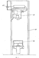
- Figure 1 schematically shows a section of an apparatus according to the invention;
- Figure 2 represent, in detail, a section of the drawing tap;
- Figure 3 shows a section of a particular embodiment of the drawing tap.
- The present invention overcomes the above said drawbacks by means of an apparatus as defined in claim 1.
- As it is shown in Figure 1 the apparatus has a
body 10, on the inferior surface of which is present a lifting means 11. - In the upper part of the
body 10, front to the lifting means 11, is placed thedrawing tap 12 which is connected to a suitable switch 12' and to the gas and electric circuits (not shown in the figure). - As shown in Figure 2 the
drawing tap 12 consists of abody 13, an electric valve 14 (and the corresponding magnet 14') and atap 15 which can engage with the bottle neck through its conical mouth 15'. - The
electric valve 14 is, preferably, a membrane electric valve. - Inside the
body 13 of thedrawing tap 12 are present: - a
channel 16 permitting the entry into the bottle of the inert gas (connected with the pipe of the gas circuit not shown in the figure); - a
channel 17 wherein flows the drawn liquid, connected on one side to thepipe 18 and to the opposite side to thespout 19. - The
channel 17 presents achamber 20 closed by the piston of theelectric valve 14 and abranch 21 which is also connected with the inert gas circuit (not shown in the figure). - The
tap 15 can be solidly connected to thebody 13 through achamber 22 or, according to a preferred embodiment of the invention, can be free to move up and down insuch chamber 22, in this case aspring 23 is present in thechamber 22 and pushes thetap 15 downwards. - On the external part of the tap 15 a gasket 24 (normally a rubber ring) is present .
- According to this second preferred embodiment, the
channel 16 at the end which enters intochamber 22 is closed by aneedle valve 25. In this case, as it can be seen from Fig. 3, thetap 15, when moving upwards will act onsuch needle valve 25, allowing the automatic entry of the gas fromchannel 16 into the bottle. - Through the mouth 15' of the
tap 15 passes the pipe 18 (preferably in flexible material) which is connected to thechannel 17 and through which the liquid flows from the bottle to thespout 19. - The lifting means 11 can be moved manually, mechanically, electrically or pneumatically (possibly connected to the inert gas circuit) and will lift the bottle until the bottle neck enters the conic mouth 15' of the
tap 15 and adheres to thegasket 24. - The upper surface of the lifting means is preferably made of, or covered with, anti-slipping materials.
- Suitable gaskets 26 (for example O-Rings) assure the seal of the electric valve and the tap 15 (when in the moving version).
- The apparatus obviously comprises the necessary hydraulic and electric circuits, and the inert gas tank, used for the apparatuses already known in the art for the same purposes. The hydraulic circuit connects the gas tank to the drawing tap and possibly to the lifting mechanism of the lifting means 11, and comprises the suitable means (valves, manometers etc.) for controlling and stabilising the gas pressure to the wanted predetermined values, while the electric circuit will activate the electric parts of the apparatus (switchers, electric valve etc).
- According to a particular embodiment of the invention the means regulating hydraulic and electric functions (pressure, switching on/off, drawing times, etc.) can be controlled by a suitable software, which can possibly be activated by the user through a personalised magnetic card allowing also the automatic debiting of the draught.
- The functioning of the apparatus according to the invention is extremely simple.
- The
pipe 18 is threaded into the bottle and the bottle is placed on the lifting means 11. - Acting on the lifting means 11 the bottle is lifted until the top of the neck adheres to the
gasket 24. - Acting on a suitable switch the gas is loaded into the bottle through the
channel 16 bringing the liquid under the desired pressure. If thetap 15 is fitted with the needle valve (as illustrated in Fig. 3) the loading of the gas will take place automatically when the bottle neck pushes on thetap 15. - The apparatus is now ready for the drawing out of the liquid.
- The user will switch on the apparatus, for example acting on a suitable switch or by introducing in the suitable inlet a magnetic card (which can be personalised by a code number) and thereafter acting on the suitable switch 12' will open the corresponding electric valve. The gas under pressure contained in the bottle will push the liquid through the
pipe 18, thechannel 17 and thechamber 22, up to thespout 19 where it will be collected by the user. - Once the predetermined quantity of liquid has been drawn the electric valve will close and, after a short interval of time necessary to permit the flowing of the liquid remaining in
channel 17 under thebranch 21, a jet of gas is blown in throughsuch branch 21, cleaning perfectly the drops of liquid remaining in thechannel 17 and thespout 19. - The apparatus will be ready for a new draught.
- Once the bottle is empty the lifting means 11 are lowered and the bottle is unthreaded from the
pipe 18 and a new bottle is installed. It is worth considering that during the substitution thepipe 18 hangs in the air and can not come into contact with possible sources of organic or inorganic polluters - Moreover it should also be noted that the whole operation can be performed by the operator with just one hand.
- The apparatus according to the invention can obviously house more than one bottle each containing the same or different liquids (for example different vintages of the same wine), in this case the presence of the software will make easier a quick debiting of the costs depending on the liquid drawn.
Claims (9)
- Apparatus for the automatic drawing out of liquids from bottles, by applying a pressure on the liquid by an inert gas being supplied by an inert gas circuit, wherein the bottles are kept in upright position, the apparatus comprising a first body (10), lifting means (11) which can be moved manually, mechanically, electrically or pneumatically the lifting means being placed at the inferior part of the first body (10), a spout and a drawing tap (12) consisting of a second body (13) characterised in that said drawing tap (12) (15) having a conical mouth (15') and inside said second body (13) are present:- a channel (16), permitting the entry of said inert gas into the bottle, being connected to the pipe of the inert gas circuit;- a channel (17) connected with its first side to a pipe (18) through which said liquid is drawn out of the bottle and with its second side to the spout (19) and presenting a chamber (20) closed by a piston of an electric valve (14) and a branch (21) being also connected to said inert gas circuit.
- Apparatus according to claim 1 wherein the tap (15) is solidly connected to the body (13) through a chamber (22).
- Apparatus according to Claim 1 wherein the tap (15) is free to move up and down in a chamber (22).
- Apparatus according to Claim 3 wherein in said chamber (22) is present a spring (23) which pushes the tap (15) downwards.
- Apparatus according to Claim 4 wherein the channel (16), at the end which enters into chamber (22), is closed by a needle valve (25).
- Apparatus according to claims 1 - 5 wherein the means regulating the hydraulic and electric functions are controlled by a software.
- Apparatus according to Claims 1 - 6 wherein the activation of the apparatus is performed by introducing a magnetic card in the suitable inlet.
- Apparatus according to claims 1 - 7 wherein the body (10) houses more than one bottle.
- Method for drawing liquids from a bottle through the action of an inert gas pushing on the liquid contained in the bottle, wherein an apparatus according to claims 1 - 8 is used.
Priority Applications (17)
| Application Number | Priority Date | Filing Date | Title |
|---|---|---|---|
| EP20020007998 EP1352873B1 (en) | 2002-04-10 | 2002-04-10 | Beverage dispenser |
| PT02007998T PT1352873E (en) | 2002-04-10 | 2002-04-10 | Beverage dispenser |
| ES02007998T ES2273938T3 (en) | 2002-04-10 | 2002-04-10 | DRINK DISPENSER. |
| AT02007998T ATE341522T1 (en) | 2002-04-10 | 2002-04-10 | DRINK DISPENSER |
| DK02007998T DK1352873T3 (en) | 2002-04-10 | 2002-04-10 | beverage dispenser |
| DE2002615116 DE60215116T2 (en) | 2002-04-10 | 2002-04-10 | Soda Fountain |
| KR1020047016138A KR100938711B1 (en) | 2002-04-10 | 2003-04-09 | Beverage dispenser |
| CA 2482256 CA2482256A1 (en) | 2002-04-10 | 2003-04-09 | Beverage dispenser |
| CN03808127A CN100590061C (en) | 2002-04-10 | 2003-04-09 | Beverage dispenser |
| US10/511,590 US7478737B2 (en) | 2002-04-10 | 2003-04-09 | Beverage dispenser |
| AU2003224053A AU2003224053B2 (en) | 2002-04-10 | 2003-04-09 | Beverage dispenser |
| JP2003582069A JP4417725B2 (en) | 2002-04-10 | 2003-04-09 | Beverage dispenser |
| PCT/EP2003/003671 WO2003084860A1 (en) | 2002-04-10 | 2003-04-09 | Beverage dispenser |
| NZ535712A NZ535712A (en) | 2002-04-10 | 2003-04-09 | Beverage dispenser |
| HK04102661A HK1059769A1 (en) | 2002-04-10 | 2004-04-15 | Beverage dispenser |
| ZA200409072A ZA200409072B (en) | 2002-04-10 | 2004-11-09 | Beverage dispenser. |
| CY061101854T CY1107318T1 (en) | 2002-04-10 | 2006-12-27 | Refrigerator Distributor |
Applications Claiming Priority (1)
| Application Number | Priority Date | Filing Date | Title |
|---|---|---|---|
| EP20020007998 EP1352873B1 (en) | 2002-04-10 | 2002-04-10 | Beverage dispenser |
Publications (2)
| Publication Number | Publication Date |
|---|---|
| EP1352873A1 EP1352873A1 (en) | 2003-10-15 |
| EP1352873B1 true EP1352873B1 (en) | 2006-10-04 |
Family
ID=28051764
Family Applications (1)
| Application Number | Title | Priority Date | Filing Date |
|---|---|---|---|
| EP20020007998 Expired - Lifetime EP1352873B1 (en) | 2002-04-10 | 2002-04-10 | Beverage dispenser |
Country Status (17)
| Country | Link |
|---|---|
| US (1) | US7478737B2 (en) |
| EP (1) | EP1352873B1 (en) |
| JP (1) | JP4417725B2 (en) |
| KR (1) | KR100938711B1 (en) |
| CN (1) | CN100590061C (en) |
| AT (1) | ATE341522T1 (en) |
| AU (1) | AU2003224053B2 (en) |
| CA (1) | CA2482256A1 (en) |
| CY (1) | CY1107318T1 (en) |
| DE (1) | DE60215116T2 (en) |
| DK (1) | DK1352873T3 (en) |
| ES (1) | ES2273938T3 (en) |
| HK (1) | HK1059769A1 (en) |
| NZ (1) | NZ535712A (en) |
| PT (1) | PT1352873E (en) |
| WO (1) | WO2003084860A1 (en) |
| ZA (1) | ZA200409072B (en) |
Families Citing this family (25)
| Publication number | Priority date | Publication date | Assignee | Title |
|---|---|---|---|---|
| US20070181602A1 (en) | 2006-02-07 | 2007-08-09 | Napa Technology, Llc | Method and apparatus for liquid dispensing head and system |
| US10631558B2 (en) | 2006-03-06 | 2020-04-28 | The Coca-Cola Company | Methods and apparatuses for making compositions comprising an acid and an acid degradable component and/or compositions comprising a plurality of selectable components |
| US8033431B2 (en) | 2007-05-07 | 2011-10-11 | Wine Gadgets, Llc | Wine preservation and dispensing apparatus |
| US8162176B2 (en) | 2007-09-06 | 2012-04-24 | The Coca-Cola Company | Method and apparatuses for providing a selectable beverage |
| ITFI20080073A1 (en) * | 2008-04-10 | 2009-10-11 | Egraf Lineadue S R L | DRINKING DRINKING EQUIPMENT, IN PARTICULAR BUT NOT ONLY WINES |
| US20100005811A1 (en) * | 2008-07-11 | 2010-01-14 | Danene Jaffe | Beverage Preservation, Chilling, and Dispensing System |
| US20110000250A1 (en) * | 2008-12-22 | 2011-01-06 | Sommerfield Matthew A | Beverage preservation and dispensing apparatus incorporated within a refrigerator door |
| ITFI20100137A1 (en) * | 2010-06-28 | 2011-12-29 | Enomatic Srl | BATH DISPENSING DEVICE FROM CONTAINERS SUCH AS BOTTLES AND SIMILAR, PROVIDED WITH ENVIRONMENTAL PARAMETER SENSORS AND ASSOCIATED CONTROL METHOD. |
| IT1400676B1 (en) * | 2010-06-29 | 2013-06-28 | Enomatic Srl | TAP FOR DISPOSAL DEVICES FOR DRINKS FROM CONTAINERS SUCH AS BOTTLES AND THE LIKE. |
| ITPO20110015A1 (en) | 2011-07-16 | 2013-01-17 | Barnini Francesca | DEVICE FOR DISTRIBUTION OF LIQUIDS, IN PARTICULAR DRINKS |
| JP5877522B2 (en) * | 2011-08-23 | 2016-03-08 | 株式会社ヨナタン | A device that automatically extracts the liquid in the bottle |
| US9856128B2 (en) | 2012-04-25 | 2018-01-02 | Richard A. Bishel | Motorized liquid dispenser |
| ITFI20130124A1 (en) | 2013-05-28 | 2014-11-29 | Enomatic S R L | AUTOMATIC CENTERING SYSTEM FOR BOTTLES AND CONTAINERS INSIDE THE EQUIPMENT FOR DRINKING BEVERAGES. |
| JP2016527148A (en) * | 2013-06-14 | 2016-09-08 | コラヴィン,インコーポレイテッド | Beverage extraction method and apparatus having improved gas cylinder access |
| FR3007999B1 (en) | 2013-07-03 | 2015-07-17 | 10 Vins | PROCESS AND INSTALLATION FOR THE PREPARATION FOR THE TASTING OF BEVERAGE, IN PARTICULAR WINE |
| KR101482732B1 (en) | 2013-08-21 | 2015-01-14 | 김용 | Wine dispenser |
| KR101438428B1 (en) * | 2013-09-10 | 2014-11-03 | (주)에스이랩 | Wine dispenser |
| BE1022304B1 (en) | 2014-06-02 | 2016-03-14 | TACHENY Thierry | BOX WITH INSIDE BAG FOR LIQUID FOOD |
| US11795046B2 (en) | 2015-11-25 | 2023-10-24 | Coravin, Inc. | Beverage dispenser with container engagement features |
| EP3380432A1 (en) | 2015-11-25 | 2018-10-03 | Coravin, Inc. | Beverage extractor with controller |
| IT201600107213A1 (en) | 2016-10-25 | 2018-04-25 | Enomatic S R L | Device for dispensing beverages by the glass equipped with a space-saving container |
| FR3064994B1 (en) | 2017-04-07 | 2019-06-21 | Noxoe, Unipessoal Lda | GLASS SERVICE DEVICE |
| JP6508847B2 (en) * | 2017-06-19 | 2019-05-08 | 株式會社塩山製作所 | Wine server |
| CN113412233B (en) | 2018-11-21 | 2023-07-07 | 科拉温股份有限公司 | Beverage dispenser with conduit purge feature |
| IT201900000659A1 (en) * | 2019-01-16 | 2020-07-16 | Gilardi Massimo | DEVICE FOR THE STORAGE OF LIQUIDS |
Family Cites Families (13)
| Publication number | Priority date | Publication date | Assignee | Title |
|---|---|---|---|---|
| US4350187A (en) * | 1980-06-25 | 1982-09-21 | Pneumatic Scale Corporation | Filling machine |
| JPS63163191U (en) * | 1987-04-13 | 1988-10-25 | ||
| FR2616767B1 (en) * | 1987-06-22 | 1990-02-16 | Cruover Sa | DEVICE FOR PROVIDING BOTTLED LIQUID BEVERAGE, ESPECIALLY WINE |
| US5031799A (en) * | 1989-02-17 | 1991-07-16 | Charlie O Company, Inc. | Seltzer dispenser for use with a home soda dispensing system |
| US5505349A (en) * | 1990-02-09 | 1996-04-09 | Berg Company, A Division Of Dec International, Inc. | Electronic dispensing heads |
| US5163584A (en) * | 1990-12-18 | 1992-11-17 | Polyfoam Products, Inc. | Method and apparatus for mixing and dispensing foam with injected low pressure gas |
| DE9300928U1 (en) * | 1993-01-23 | 1993-03-11 | Schulze, Norbert, 4790 Paderborn, De | |
| DE9307040U1 (en) * | 1993-05-08 | 1993-07-15 | Fac Frank Abels Consulting & Technology Gmbh, 3042 Munster, De | |
| US5524683A (en) * | 1994-09-23 | 1996-06-11 | Osgood Industries, Inc. | Method and apparatus for filling containers |
| US5913454A (en) * | 1998-04-09 | 1999-06-22 | Mchale; Jay T. | Drink dispensing machine |
| DE19948471C2 (en) | 1999-10-08 | 2001-11-08 | Till Gea Gmbh & Co | Dispensing system and its use |
| JP4250314B2 (en) * | 2000-07-19 | 2009-04-08 | ホシザキ電機株式会社 | Correction method and apparatus for cock driving device in beverage dispenser |
| ATE535060T1 (en) * | 2004-05-13 | 2011-12-15 | Ntt Docomo Inc | APPARATUS AND METHOD FOR PATH SEARCHING IN A CDMA RECEIVER |
-
2002
- 2002-04-10 DE DE2002615116 patent/DE60215116T2/en not_active Expired - Lifetime
- 2002-04-10 AT AT02007998T patent/ATE341522T1/en active
- 2002-04-10 ES ES02007998T patent/ES2273938T3/en not_active Expired - Lifetime
- 2002-04-10 EP EP20020007998 patent/EP1352873B1/en not_active Expired - Lifetime
- 2002-04-10 DK DK02007998T patent/DK1352873T3/en active
- 2002-04-10 PT PT02007998T patent/PT1352873E/en unknown
-
2003
- 2003-04-09 AU AU2003224053A patent/AU2003224053B2/en not_active Ceased
- 2003-04-09 JP JP2003582069A patent/JP4417725B2/en not_active Expired - Fee Related
- 2003-04-09 CA CA 2482256 patent/CA2482256A1/en not_active Abandoned
- 2003-04-09 CN CN03808127A patent/CN100590061C/en not_active Expired - Fee Related
- 2003-04-09 WO PCT/EP2003/003671 patent/WO2003084860A1/en active Application Filing
- 2003-04-09 NZ NZ535712A patent/NZ535712A/en not_active IP Right Cessation
- 2003-04-09 KR KR1020047016138A patent/KR100938711B1/en not_active IP Right Cessation
- 2003-04-09 US US10/511,590 patent/US7478737B2/en not_active Expired - Fee Related
-
2004
- 2004-04-15 HK HK04102661A patent/HK1059769A1/en not_active IP Right Cessation
- 2004-11-09 ZA ZA200409072A patent/ZA200409072B/en unknown
-
2006
- 2006-12-27 CY CY061101854T patent/CY1107318T1/en unknown
Also Published As
| Publication number | Publication date |
|---|---|
| NZ535712A (en) | 2009-11-27 |
| AU2003224053A1 (en) | 2003-10-20 |
| KR100938711B1 (en) | 2010-01-25 |
| KR20050012231A (en) | 2005-01-31 |
| JP2005522381A (en) | 2005-07-28 |
| CA2482256A1 (en) | 2003-10-16 |
| ZA200409072B (en) | 2005-06-01 |
| DK1352873T3 (en) | 2007-01-15 |
| JP4417725B2 (en) | 2010-02-17 |
| HK1059769A1 (en) | 2004-07-16 |
| WO2003084860A1 (en) | 2003-10-16 |
| CN100590061C (en) | 2010-02-17 |
| AU2003224053B2 (en) | 2009-09-17 |
| US20050150549A1 (en) | 2005-07-14 |
| US7478737B2 (en) | 2009-01-20 |
| ATE341522T1 (en) | 2006-10-15 |
| DE60215116D1 (en) | 2006-11-16 |
| ES2273938T3 (en) | 2007-05-16 |
| CN1646414A (en) | 2005-07-27 |
| DE60215116T2 (en) | 2007-05-03 |
| PT1352873E (en) | 2007-01-31 |
| EP1352873A1 (en) | 2003-10-15 |
| CY1107318T1 (en) | 2012-11-21 |
Similar Documents
| Publication | Publication Date | Title |
|---|---|---|
| EP1352873B1 (en) | Beverage dispenser | |
| US7469726B2 (en) | Beverage bottling plant for filling bottles with a liquid beverage, having a filling machine with a rotary construction for filling bottles with a liquid beverage | |
| US10370234B2 (en) | Filling device for filling machine | |
| AU756968B2 (en) | Method for the preservation of an opened drink bottle | |
| US6213169B1 (en) | Single-chamber filling system | |
| US6192946B1 (en) | Bottling system | |
| US9187196B2 (en) | Tap for beverage dispensing from receptacles such as bottles and the like | |
| US6397909B1 (en) | Apparatus and method for dispensing a carbonated beverage with minimal/controlled foaming under system pressure | |
| ATA345887A (en) | DEVICE FOR DRINKING PRESSURE BEVERAGES, IN PARTICULAR BEER | |
| US20060283518A1 (en) | Counter-pressure filling device and method of counter-pressure filling | |
| JPH07187292A (en) | Method and device to fill carbonated beverage | |
| US3880330A (en) | Liquid dispensing system and receptacle therefor | |
| US5620117A (en) | Exchangeable closing and pouring cap | |
| US9630827B2 (en) | Dispenser device of carbonated beverages | |
| EP0783433B1 (en) | Gas actuator assembly | |
| WO2015065705A1 (en) | System for re-pressurization of bottles | |
| RU160755U1 (en) | MANUFACTURER FOR MANUAL DOUBLE-THREAD FILLING OF FOAMING BEVERAGES | |
| CA2202359C (en) | Gas actuator assembly | |
| DE60101715D1 (en) | Hand operated device for pulling stoppers from containers for carbonated drinks, sparkling wines and the like | |
| EP0077973A3 (en) | Liquid dispenser device | |
| WO1997042122A2 (en) | Control volume liquid filling apparatus and method | |
| GB190917762A (en) | Improvements in Apparatus for Withdrawing Small Quantities of Aerated Liquids from Bottles and similar Vessels. | |
| CZ2003992A3 (en) | Bottle cap, especially PET bottles, equipped with a valve for easy pouring of liquids | |
| GB190220610A (en) | Improvements in Portable Vessels or Receptacles for Containing Beer and other Liquids. | |
| GB2323895A (en) | Device for dispensing liquids |
Legal Events
| Date | Code | Title | Description |
|---|---|---|---|
| PUAI | Public reference made under article 153(3) epc to a published international application that has entered the european phase |
Free format text: ORIGINAL CODE: 0009012 |
|
| AK | Designated contracting states |
Kind code of ref document: A1 Designated state(s): AT BE CH CY DE DK ES FI FR GB GR IE IT LI LU MC NL PT SE TR |
|
| AX | Request for extension of the european patent |
Extension state: AL LT LV MK RO SI |
|
| 17P | Request for examination filed |
Effective date: 20040409 |
|
| AKX | Designation fees paid |
Designated state(s): AT BE CH CY DE DK ES FI FR GB GR IE IT LI LU MC NL PT SE TR |
|
| REG | Reference to a national code |
Ref country code: HK Ref legal event code: DE Ref document number: 1059769 Country of ref document: HK |
|
| 17Q | First examination report despatched |
Effective date: 20040930 |
|
| GRAP | Despatch of communication of intention to grant a patent |
Free format text: ORIGINAL CODE: EPIDOSNIGR1 |
|
| GRAS | Grant fee paid |
Free format text: ORIGINAL CODE: EPIDOSNIGR3 |
|
| GRAA | (expected) grant |
Free format text: ORIGINAL CODE: 0009210 |
|
| AK | Designated contracting states |
Kind code of ref document: B1 Designated state(s): AT BE CH CY DE DK ES FI FR GB GR IE IT LI LU MC NL PT SE TR |
|
| PG25 | Lapsed in a contracting state [announced via postgrant information from national office to epo] |
Ref country code: IT Free format text: LAPSE BECAUSE OF FAILURE TO SUBMIT A TRANSLATION OF THE DESCRIPTION OR TO PAY THE FEE WITHIN THE PRESCRIBED TIME-LIMIT;WARNING: LAPSES OF ITALIAN PATENTS WITH EFFECTIVE DATE BEFORE 2007 MAY HAVE OCCURRED AT ANY TIME BEFORE 2007. THE CORRECT EFFECTIVE DATE MAY BE DIFFERENT FROM THE ONE RECORDED. Effective date: 20061004 |
|
| REG | Reference to a national code |
Ref country code: GB Ref legal event code: FG4D |
|
| REG | Reference to a national code |
Ref country code: CH Ref legal event code: EP |
|
| REG | Reference to a national code |
Ref country code: IE Ref legal event code: FG4D |
|
| REF | Corresponds to: |
Ref document number: 60215116 Country of ref document: DE Date of ref document: 20061116 Kind code of ref document: P |
|
| REG | Reference to a national code |
Ref country code: DK Ref legal event code: T3 |
|
| REG | Reference to a national code |
Ref country code: SE Ref legal event code: TRGR |
|
| REG | Reference to a national code |
Ref country code: PT Ref legal event code: SC4A Free format text: AVAILABILITY OF NATIONAL TRANSLATION Effective date: 20061221 |
|
| REG | Reference to a national code |
Ref country code: GR Ref legal event code: EP Ref document number: 20070400027 Country of ref document: GR |
|
| REG | Reference to a national code |
Ref country code: CH Ref legal event code: NV Representative=s name: N&G PATENT SERVICES SA |
|
| ET | Fr: translation filed | ||
| REG | Reference to a national code |
Ref country code: HK Ref legal event code: GR Ref document number: 1059769 Country of ref document: HK |
|
| REG | Reference to a national code |
Ref country code: ES Ref legal event code: FG2A Ref document number: 2273938 Country of ref document: ES Kind code of ref document: T3 |
|
| PLBE | No opposition filed within time limit |
Free format text: ORIGINAL CODE: 0009261 |
|
| STAA | Information on the status of an ep patent application or granted ep patent |
Free format text: STATUS: NO OPPOSITION FILED WITHIN TIME LIMIT |
|
| 26N | No opposition filed |
Effective date: 20070705 |
|
| PGRI | Patent reinstated in contracting state [announced from national office to epo] |
Ref country code: IT Effective date: 20110616 |
|
| PGFP | Annual fee paid to national office [announced via postgrant information from national office to epo] |
Ref country code: LU Payment date: 20120411 Year of fee payment: 11 Ref country code: TR Payment date: 20120411 Year of fee payment: 11 Ref country code: NL Payment date: 20120412 Year of fee payment: 11 Ref country code: BE Payment date: 20120423 Year of fee payment: 11 Ref country code: CH Payment date: 20120411 Year of fee payment: 11 Ref country code: MC Payment date: 20120412 Year of fee payment: 11 Ref country code: DK Payment date: 20120411 Year of fee payment: 11 Ref country code: IE Payment date: 20120411 Year of fee payment: 11 |
|
| PGFP | Annual fee paid to national office [announced via postgrant information from national office to epo] |
Ref country code: SE Payment date: 20120411 Year of fee payment: 11 Ref country code: FI Payment date: 20120411 Year of fee payment: 11 Ref country code: GR Payment date: 20120412 Year of fee payment: 11 |
|
| PGFP | Annual fee paid to national office [announced via postgrant information from national office to epo] |
Ref country code: CY Payment date: 20120504 Year of fee payment: 11 |
|
| PGFP | Annual fee paid to national office [announced via postgrant information from national office to epo] |
Ref country code: ES Payment date: 20120413 Year of fee payment: 11 |
|
| PGFP | Annual fee paid to national office [announced via postgrant information from national office to epo] |
Ref country code: PT Payment date: 20120411 Year of fee payment: 11 |
|
| PGFP | Annual fee paid to national office [announced via postgrant information from national office to epo] |
Ref country code: AT Payment date: 20120412 Year of fee payment: 11 |
|
| PGFP | Annual fee paid to national office [announced via postgrant information from national office to epo] |
Ref country code: GB Payment date: 20130312 Year of fee payment: 12 |
|
| PGFP | Annual fee paid to national office [announced via postgrant information from national office to epo] |
Ref country code: DE Payment date: 20130321 Year of fee payment: 12 |
|
| REG | Reference to a national code |
Ref country code: PT Ref legal event code: MM4A Free format text: LAPSE DUE TO NON-PAYMENT OF FEES Effective date: 20131010 |
|
| BERE | Be: lapsed |
Owner name: ENOMATIC S.R.L. Effective date: 20130430 |
|
| REG | Reference to a national code |
Ref country code: NL Ref legal event code: V1 Effective date: 20131101 |
|
| PG25 | Lapsed in a contracting state [announced via postgrant information from national office to epo] |
Ref country code: MC Free format text: LAPSE BECAUSE OF NON-PAYMENT OF DUE FEES Effective date: 20130430 |
|
| REG | Reference to a national code |
Ref country code: CH Ref legal event code: PL |
|
| REG | Reference to a national code |
Ref country code: SE Ref legal event code: EUG |
|
| REG | Reference to a national code |
Ref country code: DK Ref legal event code: EBP Effective date: 20130430 |
|
| REG | Reference to a national code |
Ref country code: AT Ref legal event code: MM01 Ref document number: 341522 Country of ref document: AT Kind code of ref document: T Effective date: 20130430 |
|
| REG | Reference to a national code |
Ref country code: GR Ref legal event code: ML Ref document number: 20070400027 Country of ref document: GR Effective date: 20131104 |
|
| REG | Reference to a national code |
Ref country code: IE Ref legal event code: MM4A |
|
| PG25 | Lapsed in a contracting state [announced via postgrant information from national office to epo] |
Ref country code: LI Free format text: LAPSE BECAUSE OF NON-PAYMENT OF DUE FEES Effective date: 20130430 Ref country code: SE Free format text: LAPSE BECAUSE OF NON-PAYMENT OF DUE FEES Effective date: 20130411 Ref country code: CH Free format text: LAPSE BECAUSE OF NON-PAYMENT OF DUE FEES Effective date: 20130430 Ref country code: CY Free format text: LAPSE BECAUSE OF FAILURE TO SUBMIT A TRANSLATION OF THE DESCRIPTION OR TO PAY THE FEE WITHIN THE PRESCRIBED TIME-LIMIT Effective date: 20130619 Ref country code: PT Free format text: LAPSE BECAUSE OF NON-PAYMENT OF DUE FEES Effective date: 20131010 Ref country code: BE Free format text: LAPSE BECAUSE OF NON-PAYMENT OF DUE FEES Effective date: 20130430 Ref country code: AT Free format text: LAPSE BECAUSE OF NON-PAYMENT OF DUE FEES Effective date: 20130430 |
|
| PG25 | Lapsed in a contracting state [announced via postgrant information from national office to epo] |
Ref country code: NL Free format text: LAPSE BECAUSE OF NON-PAYMENT OF DUE FEES Effective date: 20131101 Ref country code: FI Free format text: LAPSE BECAUSE OF NON-PAYMENT OF DUE FEES Effective date: 20130410 Ref country code: GR Free format text: LAPSE BECAUSE OF NON-PAYMENT OF DUE FEES Effective date: 20131104 |
|
| PG25 | Lapsed in a contracting state [announced via postgrant information from national office to epo] |
Ref country code: CY Free format text: LAPSE BECAUSE OF FAILURE TO SUBMIT A TRANSLATION OF THE DESCRIPTION OR TO PAY THE FEE WITHIN THE PRESCRIBED TIME-LIMIT Effective date: 20130410 |
|
| PG25 | Lapsed in a contracting state [announced via postgrant information from national office to epo] |
Ref country code: DK Free format text: LAPSE BECAUSE OF NON-PAYMENT OF DUE FEES Effective date: 20130430 Ref country code: IE Free format text: LAPSE BECAUSE OF NON-PAYMENT OF DUE FEES Effective date: 20130410 |
|
| PGFP | Annual fee paid to national office [announced via postgrant information from national office to epo] |
Ref country code: FR Payment date: 20140313 Year of fee payment: 13 |
|
| REG | Reference to a national code |
Ref country code: ES Ref legal event code: FD2A Effective date: 20140610 |
|
| PG25 | Lapsed in a contracting state [announced via postgrant information from national office to epo] |
Ref country code: ES Free format text: LAPSE BECAUSE OF NON-PAYMENT OF DUE FEES Effective date: 20130411 |
|
| PGFP | Annual fee paid to national office [announced via postgrant information from national office to epo] |
Ref country code: IT Payment date: 20140402 Year of fee payment: 13 |
|
| REG | Reference to a national code |
Ref country code: DE Ref legal event code: R119 Ref document number: 60215116 Country of ref document: DE |
|
| GBPC | Gb: european patent ceased through non-payment of renewal fee |
Effective date: 20140410 |
|
| REG | Reference to a national code |
Ref country code: DE Ref legal event code: R119 Ref document number: 60215116 Country of ref document: DE Effective date: 20141101 |
|
| PG25 | Lapsed in a contracting state [announced via postgrant information from national office to epo] |
Ref country code: DE Free format text: LAPSE BECAUSE OF NON-PAYMENT OF DUE FEES Effective date: 20141101 Ref country code: GB Free format text: LAPSE BECAUSE OF NON-PAYMENT OF DUE FEES Effective date: 20140410 |
|
| PG25 | Lapsed in a contracting state [announced via postgrant information from national office to epo] |
Ref country code: LU Free format text: LAPSE BECAUSE OF NON-PAYMENT OF DUE FEES Effective date: 20130410 |
|
| PG25 | Lapsed in a contracting state [announced via postgrant information from national office to epo] |
Ref country code: TR Free format text: LAPSE BECAUSE OF NON-PAYMENT OF DUE FEES Effective date: 20130410 |
|
| PG25 | Lapsed in a contracting state [announced via postgrant information from national office to epo] |
Ref country code: IT Free format text: LAPSE BECAUSE OF FAILURE TO SUBMIT A TRANSLATION OF THE DESCRIPTION OR TO PAY THE FEE WITHIN THE PRESCRIBED TIME-LIMIT Effective date: 20150410 |
|
| REG | Reference to a national code |
Ref country code: FR Ref legal event code: ST Effective date: 20151231 |
|
| PG25 | Lapsed in a contracting state [announced via postgrant information from national office to epo] |
Ref country code: FR Free format text: LAPSE BECAUSE OF NON-PAYMENT OF DUE FEES Effective date: 20150430 |