EP1352690B1 - Swivel pump dispenser for dispensing liquid from a selected one of a plurality of liquid compartments - Google Patents
Swivel pump dispenser for dispensing liquid from a selected one of a plurality of liquid compartments Download PDFInfo
- Publication number
- EP1352690B1 EP1352690B1 EP03445044A EP03445044A EP1352690B1 EP 1352690 B1 EP1352690 B1 EP 1352690B1 EP 03445044 A EP03445044 A EP 03445044A EP 03445044 A EP03445044 A EP 03445044A EP 1352690 B1 EP1352690 B1 EP 1352690B1
- Authority
- EP
- European Patent Office
- Prior art keywords
- liquid
- swivel
- pump
- openings
- vent
- Prior art date
- Legal status (The legal status is an assumption and is not a legal conclusion. Google has not performed a legal analysis and makes no representation as to the accuracy of the status listed.)
- Expired - Lifetime
Links
- 239000007788 liquid Substances 0.000 title claims abstract description 61
- 238000004891 communication Methods 0.000 claims description 9
- 239000012530 fluid Substances 0.000 claims description 3
- 230000000694 effects Effects 0.000 claims description 2
- 238000013022 venting Methods 0.000 abstract description 6
- 238000007789 sealing Methods 0.000 abstract 1
- 239000000047 product Substances 0.000 description 15
- 230000006835 compression Effects 0.000 description 4
- 238000007906 compression Methods 0.000 description 4
- 239000012263 liquid product Substances 0.000 description 3
- 230000001788 irregular Effects 0.000 description 2
- 238000005086 pumping Methods 0.000 description 2
- 235000008694 Humulus lupulus Nutrition 0.000 description 1
- 238000004140 cleaning Methods 0.000 description 1
- 230000008878 coupling Effects 0.000 description 1
- 238000010168 coupling process Methods 0.000 description 1
- 238000005859 coupling reaction Methods 0.000 description 1
- 239000011521 glass Substances 0.000 description 1
- 230000014759 maintenance of location Effects 0.000 description 1
- 238000012986 modification Methods 0.000 description 1
- 230000004048 modification Effects 0.000 description 1
- 238000000926 separation method Methods 0.000 description 1
Images
Classifications
-
- B—PERFORMING OPERATIONS; TRANSPORTING
- B05—SPRAYING OR ATOMISING IN GENERAL; APPLYING FLUENT MATERIALS TO SURFACES, IN GENERAL
- B05B—SPRAYING APPARATUS; ATOMISING APPARATUS; NOZZLES
- B05B11/00—Single-unit hand-held apparatus in which flow of contents is produced by the muscular force of the operator at the moment of use
- B05B11/01—Single-unit hand-held apparatus in which flow of contents is produced by the muscular force of the operator at the moment of use characterised by the means producing the flow
- B05B11/10—Pump arrangements for transferring the contents from the container to a pump chamber by a sucking effect and forcing the contents out through the dispensing nozzle
- B05B11/1081—Arrangements for pumping several liquids or other fluent materials from several containers, e.g. for mixing them at the moment of pumping
-
- B—PERFORMING OPERATIONS; TRANSPORTING
- B05—SPRAYING OR ATOMISING IN GENERAL; APPLYING FLUENT MATERIALS TO SURFACES, IN GENERAL
- B05B—SPRAYING APPARATUS; ATOMISING APPARATUS; NOZZLES
- B05B11/00—Single-unit hand-held apparatus in which flow of contents is produced by the muscular force of the operator at the moment of use
- B05B11/01—Single-unit hand-held apparatus in which flow of contents is produced by the muscular force of the operator at the moment of use characterised by the means producing the flow
- B05B11/10—Pump arrangements for transferring the contents from the container to a pump chamber by a sucking effect and forcing the contents out through the dispensing nozzle
- B05B11/1001—Piston pumps
- B05B11/1009—Piston pumps actuated by a lever
- B05B11/1011—Piston pumps actuated by a lever without substantial movement of the nozzle in the direction of the pressure stroke
-
- B—PERFORMING OPERATIONS; TRANSPORTING
- B05—SPRAYING OR ATOMISING IN GENERAL; APPLYING FLUENT MATERIALS TO SURFACES, IN GENERAL
- B05B—SPRAYING APPARATUS; ATOMISING APPARATUS; NOZZLES
- B05B12/00—Arrangements for controlling delivery; Arrangements for controlling the spray area
- B05B12/14—Arrangements for controlling delivery; Arrangements for controlling the spray area for supplying a selected one of a plurality of liquids or other fluent materials or several in selected proportions to a spray apparatus, e.g. to a single spray outlet
- B05B12/1409—Arrangements for controlling delivery; Arrangements for controlling the spray area for supplying a selected one of a plurality of liquids or other fluent materials or several in selected proportions to a spray apparatus, e.g. to a single spray outlet the selection means being part of the discharge apparatus, e.g. part of the spray gun
Definitions
- This invention relates generally to a liquid pump dispenser capable of dispensing liquid from a selected one of a plurality of liquid compartments of a single compartmented container or of separate container sections.
- Various household and commercial cleaning products are used for a variety of purposes in a room of the home or office requiring a number of separate containers each of which must be dispensed separately.
- a carpet spot removal is a special product and a wall and floor cleaner is yet another product while a glass cleaner is yet another. All these products must be stored in their on own containers with their own dispensers, causing clutter and frustration.
- a multi-compartmented container of these different products can be utilized with a single swivel pump dispenser which selects one product at a time upon rotation of the dispenser about its axis. Such reduces the need for separate containers of various household and commercial cleaners with their own dispensers, thereby saving storage space and providing for convenient multi-product dispensing.
- a single pump assembly is detachably mounted on a multi-compartmented container and rotates relative thereto to select the liquid to be pumped.
- An inlet tube of the pump assembly connects to one of several openings of a base plate of the pump assembly, from which a dip tube extends into each compartment, upon dispenser rotation for selecting the product to be dispensed.
- the pump dispenser is coupled to a base plate of the container closure by the provision of spring-biased rivet fasteners permitting the lower end of an inlet tube to be aligned with an opening in the base plate from which a dip tube extends upon dispenser rotation. To effect rotation, the pump body must be lifted against the bias of the spring and rotated.
- the upper end of each dip tube has annular recesses in which are seated O rings.
- US Patent 5152431 may be described as a swivel pump dispenser for dispensing liquid from a selected one of a plurality of liquid compartments arranged side by side, comprising a housing including a pump cylinder defining a pump chamber together with a manually reciprocable pump piston, an inlet tube in fluid communication with the pump chamber; a cap having liquid openings; dip tubes supported by the cap and each extending into a compartment from the liquid openings.
- the dispenser includes:
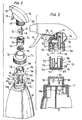
- a swivel pump dispenser assembly according to the invention as shown in Figs. 1, 2 and 3 includes a known trigger operated pump dispenser of the type disclosed in U.S. patent 6,095,377 .
- the dispenser includes a pump piston 10 operating in a cylinder 11 against the bias of a piston return spring 12 so as to form together with the cylinder a variable volume pump chamber 13.
- An inlet pipe 14 supported on a disc 15 which may be press-fitted into pump housing 16 supports the inlet pipe which defines an inlet passage 17 valved as at 18 for delivering liquid product into the pump chamber on each return stroke of the piston on relaxation of trigger lever 19.
- vent pipe 21 which defines a vent passage 22 in communication with a vent port 23 formed in the piston cylinder outboard of chamber 13 and being exposed to atmosphere during each pumping stroke as described in more detail in the aforementioned 6,095,377 patent.
- the pump housing has coupled thereto a container closure 24 which would normally be mounted to a single container of a single product. Instead, closure 24 may be thread coupled to a swivel element 25 having sleeves 26, 27 respectively telescoped with pipes 14, 21 upon coupling, forming air and liquid seals respectively.
- Base wall 28 of the swivel has a liquid opening 29 formed therein as well as a vent opening 31. Adhered, molded onto, or otherwise secured to the outer face of wall 28 is an elastomeric disc seal 32 having openings 33, 34 therein respectively in alignment with openings 29, 31.
- a cap 35 having a base wall 36 has an upwardly extended castellated sleeve 37 formed by cutouts 38 for a purpose to be described hereinafter.
- An interrupted annular inwardly extending rib 39 is formed at the upper end of sleeve 37 for the reception in annular groove 41 formed in the outer wall of swivel element 25.
- Base wall 36 of cap 35 has formed therein pairs of openings 42, 43; 44, 45; 46, 47. Openings 42, 44, 46 are liquid openings, and openings 43, 45, 47 are vent openings of the pairs. (See Figs. 4 and 6 to 8 ).
- Short sleeves 48, 49, 51 surround the respective pairs of liquid and vent openings and extend through like sized openings 52, 53, 54 in upper walls 55, 56, 57 of container sections 58, 59, 61 ( Fig. 1 ) each containing a separate liquid product (not shown) to be dispensed with the three sections being coupled together in some typical manner forming no part of the invention. Otherwise, sleeves 48, 49, 51 extend through corresponding openings in a single top wall of a single container 62 (see Fig. 5 ) formed internally in some manner with separation walls defining compartments 63, 64, 65.
- sleeves 48, 49, 51 are respectively smaller diameter and shorter tube retention sleeves 66, 67, 68 ( Fig. 4 ) respectively supporting dip tubes 76, 77, 78 each extending into the liquid in the respective containers 58, 59, 61 or in compartments 63, 64, 65 of single container 62.
- An internally threaded container closure 71 has an upstanding sleeve 70 through which castellated sleeve 37 extends upon assembly as swivel element 25 is coupled to sleeve 37 and the swivel element is coupled to the pump housing via closure 24.
- the castellated sleeve 37 thus slightly expands to permit easy reception of swivel element 25 during assembly.
- the upstanding sleeve of the internally threaded container closure (71) keeps the rib (39) in the annular groove (41) when the closure is placed over the cap (35).
- Disc seal 32 has through openings, a liquid opening 33 and a vent opening 34 extending therethrough.
- a passageway 73 of much shorter length and formed as either a groove in the disc seal or as a through opening, is associated with vent opening 34.
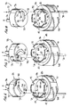
- passageway 72 interconnects one of the liquid openings 42, 44, 46 with liquid opening 33 and with liquid opening 29 of liquid inlet pipe 26 upon rotation of the pump dispenser and its swivel element selectively from Fig. 6 to Fig. 7 to Fig. 8 to Fig. 6 .
- Indexing is provided for determining the particular liquid to be dispensed upon dispenser rotation.
- Such indexing may be in the form of one or more vertical grooves 74 (keyways) provided in the inner surface of sleeve 37 for the reception of a detent 75 (key) on the outer wall of swivel element 25.
- Each groove 74 is associated with one of the liquid openings 42, 44, 46.
- the openings 42 to 47 are covered by elastomeric disc seal 32 to thereby prevent leakage of product through the vent openings in conditions of non-use, such as during shipping and storage, and in the event the dispenser package is dropped, or tipped or falls on its side.
- the operator must then choose which of the three liquids stored in containers 58, 59, 61 (or compartments 63, 64, 65 of a single container if that be the case) is selected for dispensing.
- passageway 72 overlies opening 46 from which a dip tube 76 extends as supported by sleeve 68 depending from base wall 36 of cap 35 into the liquid stored in container 58. And, passageway 73 overlies vent opening 47 which communicates with the interior of container 58 (comparably container 53 section).
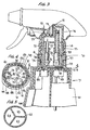
- the operator then actuates the pump by pulling on trigger 19 such that during each compression stroke (assuming the pump chamber 12 is primed with liquid) product is discharged through the discharge orifice (not shown) in nozzle cap 20.
- vent port 23 in the pump housing is open to atmosphere, as explained in more detail in the 6,095,377 patent, such that the interior of container 58 is vented to atmosphere via pipe 21, vent sleeve 27, vent opening 31, vent opening 34, passageway 73, and vent opening 47 all as in the direction of the downwardly directed arrows shown in Fig. 3 .
- liquid product stored in container 58 (comparable to container section 63) is suctioned into pump chamber 12 via dip tube 76, opening 46, passageway 72, opening 33, opening 29, sleeve 26, and inlet pipe 14, in the direction of the upwardly directed arrows seen in Fig. 3 .
- passageway 72 overlies liquid opening 42
- passageway 73 overlies vent opening 43.
- the venting during each ensuing piston compression stroke follows a similar path through 21, 27 and 31 but, compared to that of Fig. 7 , continues through vent opening 34, passageway 37, vent opening 43 and into container 59.
- passageway 72 overlies liquid opening 44
- passageway 73 overlies vent opening 45.
- Liquid is drawn up from container 61 via dip tube 78 during each piston suction stroke, and through 45, 72, 33, 26 and 14. Venting during each piston compression stroke into container 61 is via 23, 21, 27, 31, 34, 73 and 45.
- a simple and economical yet highly effective single pump dispenser package has been devised for selectively dispensing liquids from a multi-compartmented vessel or from adjoining containers in a manner which facilitates positive venting of each container compartment or each container directly to the atmosphere during the pumping of product therefrom.
- the vents from the containers are sealed closed by an elastomeric seal preventing any leakage during shipping and storage and, in the event the dispensing package is dropped or falls on its side.
- swivel element 25 could be eliminated as a separate element and made unitary with disc 15, without departing from the invention.
- passageways 72 and 73 in the elastomeric disc can be provided as either through openings as shown or as grooves of irregular configuration.
- pump dispensers having positive container venting of a type other than that disclosed herein can be utilized as a selective swivel dispenser within the purview of the invention. It is therefore to be understood that within the scope of the appended claims the invention may be practiced otherwise than as specifically described.
Landscapes
- Containers And Packaging Bodies Having A Special Means To Remove Contents (AREA)
- Closures For Containers (AREA)
- Reciprocating Pumps (AREA)
- Package Specialized In Special Use (AREA)
Applications Claiming Priority (2)
| Application Number | Priority Date | Filing Date | Title |
|---|---|---|---|
| US119071 | 2002-04-10 | ||
| US10/119,071 US6659311B2 (en) | 2002-04-10 | 2002-04-10 | Swivel pump dispenser for dispensing liquid from a selected one of plurality of liquid compartments |
Publications (2)
| Publication Number | Publication Date |
|---|---|
| EP1352690A1 EP1352690A1 (en) | 2003-10-15 |
| EP1352690B1 true EP1352690B1 (en) | 2010-06-09 |
Family
ID=28453977
Family Applications (1)
| Application Number | Title | Priority Date | Filing Date |
|---|---|---|---|
| EP03445044A Expired - Lifetime EP1352690B1 (en) | 2002-04-10 | 2003-04-07 | Swivel pump dispenser for dispensing liquid from a selected one of a plurality of liquid compartments |
Country Status (6)
| Country | Link |
|---|---|
| US (1) | US6659311B2 (enExample) |
| EP (1) | EP1352690B1 (enExample) |
| JP (1) | JP4022165B2 (enExample) |
| AT (1) | ATE470508T1 (enExample) |
| CA (1) | CA2424161A1 (enExample) |
| DE (1) | DE60332888D1 (enExample) |
Cited By (1)
| Publication number | Priority date | Publication date | Assignee | Title |
|---|---|---|---|---|
| US10138110B2 (en) | 2015-09-21 | 2018-11-27 | S. C. Johnson & Son, Inc. | Attachment and system for mixing and dispensing a chemical and diluent |
Families Citing this family (47)
| Publication number | Priority date | Publication date | Assignee | Title |
|---|---|---|---|---|
| US6769573B1 (en) * | 2002-09-13 | 2004-08-03 | Randal N. Kazarian | Multi-chambered container fluid selection valve |
| KR100494658B1 (ko) * | 2003-02-17 | 2005-06-13 | 주식회사 에프에스코리아 | 내용물 배출구조를 개선시킨 자동혼합 화장품 용기 |
| US7984832B2 (en) * | 2006-10-23 | 2011-07-26 | The Clorox Company | Pump dispenser for use with substrates |
| US7938299B2 (en) * | 2006-11-03 | 2011-05-10 | S.C. Johnson & Son, Inc. | Device for attaching a dip tube to a fluid container |
| US7871217B2 (en) * | 2006-12-12 | 2011-01-18 | The Clorox Company | Pump systems for pump dispensers |
| US20080138143A1 (en) * | 2006-12-12 | 2008-06-12 | O'connell Tami | Fluid Dispensing Systems For Pump Dispenser for Use With Substrates |
| US7980777B2 (en) * | 2007-01-09 | 2011-07-19 | The Clorox Company | Fluid dispensing system with separate pump actuator and dispensing pad |
| WO2008118446A2 (en) * | 2007-03-27 | 2008-10-02 | S. C. Johnson & Son, Inc. | Handheld device for dispensing fluids |
| US20080273915A1 (en) * | 2007-05-01 | 2008-11-06 | O'connell Tami | Sensory Cue For Pump Dispenser For Use With Substrates |
| US20080314925A1 (en) * | 2007-06-25 | 2008-12-25 | Timothy Kennedy | Gravity-Flow Liquid Drain-Back System for a Dispensing Package |
| US7775401B2 (en) | 2007-06-25 | 2010-08-17 | S.C. Johnson & Son, Inc. | Fluid delivery system for dispensing primary and secondary fluids |
| US7726517B2 (en) * | 2007-06-27 | 2010-06-01 | The Clorox Company | Liquid draw-back system for a dispensing package |
| US7712633B2 (en) * | 2007-07-02 | 2010-05-11 | The Clorox Company | Through-pump liquid drain-back system for a dispensing package |
| US20090101676A1 (en) * | 2007-10-22 | 2009-04-23 | O'connell Tami | Pump Dispenser With Indented Actuator Skirt |
| US20240226935A9 (en) * | 2009-02-19 | 2024-07-11 | Bkb Holdings Llc | Multi-chamber fluid dispenser |
| USD696747S1 (en) | 2009-06-17 | 2013-12-31 | S.C. Johnson & Son, Inc. | Container for a fluid dispensing device |
| CN104875966B (zh) | 2009-06-17 | 2017-09-22 | 约翰逊父子公司 | 用于分配流体的手持装置 |
| USD647998S1 (en) | 2009-06-17 | 2011-11-01 | S.C. Johnson & Son, Inc. | Container for a fluid dispensing device |
| USD646351S1 (en) | 2009-06-17 | 2011-10-04 | S.C. Johnson & Son, Inc. | Handheld fluid dispensing device |
| US20120018458A1 (en) * | 2010-07-26 | 2012-01-26 | Ecolab Usa Inc. | Metered dosing bottle |
| US8800818B2 (en) * | 2010-08-04 | 2014-08-12 | Evan Greenberg | Multi-chamber dispenser |
| IT1401659B1 (it) | 2010-09-16 | 2013-08-02 | Guala Dispensing Spa | Dispositivo di erogazione per liquidi |
| US8534497B2 (en) | 2010-09-20 | 2013-09-17 | Prince Castle, LLC | Dispensing method and apparatus utilizing a sensor to determine a time that a dispensing valve is open |
| US8376310B2 (en) | 2010-09-20 | 2013-02-19 | Prince Castle, LLC | Pinch valve |
| US9827581B2 (en) | 2011-03-15 | 2017-11-28 | Silgan Dispensing Systems Corporation | Dip tube connectors and pump systems using the same |
| US8844768B2 (en) | 2011-06-27 | 2014-09-30 | Prince Castle LLC | Liquid dispenser with storage tanks |
| US8636180B2 (en) | 2011-06-27 | 2014-01-28 | Prince Castle, LLC | Pinch valve |
| US8636176B2 (en) | 2011-06-27 | 2014-01-28 | Prince Castle, LLC | Liquid dispenser pinch valve |
| US8727304B2 (en) | 2011-06-27 | 2014-05-20 | Prince Castle, LLC. | Pinch bar |
| US20130248538A1 (en) | 2012-03-23 | 2013-09-26 | Prince Castle, LLC | Holding Tank With Internally Reinforced Sidewalls and Liquid Dispenser Using Same |
| GB2518854B (en) * | 2013-10-02 | 2015-08-26 | Melissa Grant | A nozzle head |
| USD717666S1 (en) | 2014-03-14 | 2014-11-18 | The Clorox Company | Fluid dispenser |
| KR101569709B1 (ko) | 2014-12-03 | 2015-11-17 | 광주여자대학교 산학협력단 | 샴푸린스 용기 |
| GB2542575A (en) * | 2015-09-22 | 2017-03-29 | Medimauve Ltd | Twin bottle manifold |
| US9988257B2 (en) | 2015-12-21 | 2018-06-05 | Prince Castle LLC | Manual dispensing valve |
| CN107089437A (zh) * | 2016-04-16 | 2017-08-25 | 宁波市鄞州乐可机电科技有限公司 | 一种按压式的清洁液瓶 |
| TWI730981B (zh) * | 2016-08-24 | 2021-06-21 | 侯欣妤 | 容器結構 |
| WO2018184064A1 (en) * | 2017-04-05 | 2018-10-11 | Kirill Petrov | Multi container dispensing arrangement |
| CA2977635A1 (en) * | 2017-08-30 | 2019-02-28 | Siamons International Inc. | Dual compartment container adapter |
| US11135609B2 (en) | 2017-12-28 | 2021-10-05 | Marene Corona | Multi-nozzle multi-container fluid spray device |
| WO2019193568A1 (en) | 2018-04-06 | 2019-10-10 | Id Packaging Inc. | Dispensing pump and manufacturing method thereof |
| CN112689539A (zh) * | 2018-07-25 | 2021-04-20 | 里克有限责任公司 | 带防泄漏通气口的喷雾分配器 |
| US12084258B1 (en) * | 2019-04-23 | 2024-09-10 | Brenda Bickford | Bottle apparatus |
| US10618705B1 (en) * | 2019-11-13 | 2020-04-14 | Rodney Laible | Dual draw cap adapter |
| USD980069S1 (en) | 2020-07-14 | 2023-03-07 | Ball Corporation | Metallic dispensing lid |
| US12168551B2 (en) | 2021-03-01 | 2024-12-17 | Ball Corporation | Metal container and end closure with seal |
| KR102637887B1 (ko) * | 2021-09-09 | 2024-02-19 | 주식회사 엔공구 | 복수의 용액이 배출되는 분무용기 |
Family Cites Families (15)
| Publication number | Priority date | Publication date | Assignee | Title |
|---|---|---|---|---|
| DE2940564A1 (de) * | 1979-10-06 | 1981-04-16 | Henkel KGaA, 4000 Düsseldorf | Fluessigkeits-vorratsbehaelter zum ankoppeln an eine spruehpumpe |
| DE3011634A1 (de) * | 1980-03-26 | 1981-10-08 | Gerhart 3000 Hannover Daubner | Mehrkammer handspraydose mit verschliessbaren duesen, oder aushebbaren drehschieber |
| GB2116261B (en) * | 1982-03-09 | 1985-07-17 | Girair Hagop Alticosalian | Perfume dispenser |
| US5009342A (en) * | 1989-08-14 | 1991-04-23 | Mark R. Miller | Dual liquid spraying assembly |
| US5152431A (en) | 1991-06-21 | 1992-10-06 | Sterling Drug, Inc. | Pump apparatus for dispensing a selected one of a plurality of liquids |
| US5370275A (en) * | 1992-09-11 | 1994-12-06 | Mills; David P. | Pump-mountable valve for selecting one of a plurality of fluids for dispensing |
| US5385270A (en) * | 1993-06-29 | 1995-01-31 | Cataneo; Ralph J. | Selectable ratio dispensing apparatus |
| US5433350A (en) * | 1994-03-15 | 1995-07-18 | Reckitt & Colman Inc. | Pump apparatus for dispensing a selected one of a plurality of liquids from a container |
| DE9413316U1 (de) * | 1994-08-18 | 1994-11-03 | Mastnak, Dirk, 86453 Dasing | Mehrkammer-Flüssigkeitsdispenser |
| US5472119A (en) * | 1994-08-22 | 1995-12-05 | S. C. Johnson & Son, Inc. | Assembly for dispensing fluids from multiple containers, while simultaneously and instantaneously venting the fluid containers |
| US5752626A (en) * | 1995-09-08 | 1998-05-19 | Owens-Illinois Closure Inc. | Simulataneous pump dispenser |
| US5626259A (en) * | 1995-11-16 | 1997-05-06 | Afa Products, Inc. | Two liquid sprayer assembly |
| US5769275A (en) * | 1996-07-08 | 1998-06-23 | Vernay Laboratories, Inc. | Dual dispensing valve assembly |
| TR199902285T2 (xx) * | 1997-03-27 | 1999-12-21 | Unilever N.V. | Bir s�v�y�, �zellikle sprey p�sk�rt�c�yle birlikte �al��t�r�labilen inceltilebilir bir konsantreyi muhafaza etmek i�in cihaz. |
| US6095377A (en) | 1999-03-26 | 2000-08-01 | Calmar Inc. | Liquid dispensing pump |
-
2002
- 2002-04-10 US US10/119,071 patent/US6659311B2/en not_active Expired - Lifetime
-
2003
- 2003-04-01 CA CA002424161A patent/CA2424161A1/en not_active Abandoned
- 2003-04-07 DE DE60332888T patent/DE60332888D1/de not_active Expired - Lifetime
- 2003-04-07 AT AT03445044T patent/ATE470508T1/de not_active IP Right Cessation
- 2003-04-07 EP EP03445044A patent/EP1352690B1/en not_active Expired - Lifetime
- 2003-04-10 JP JP2003106760A patent/JP4022165B2/ja not_active Expired - Fee Related
Cited By (2)
| Publication number | Priority date | Publication date | Assignee | Title |
|---|---|---|---|---|
| US10138110B2 (en) | 2015-09-21 | 2018-11-27 | S. C. Johnson & Son, Inc. | Attachment and system for mixing and dispensing a chemical and diluent |
| US10669146B2 (en) | 2015-09-21 | 2020-06-02 | S.C. Johnson & Son, Inc. | Attachment and system for mixing and dispensing a chemical and diluent |
Also Published As
| Publication number | Publication date |
|---|---|
| CA2424161A1 (en) | 2003-10-10 |
| JP4022165B2 (ja) | 2007-12-12 |
| US6659311B2 (en) | 2003-12-09 |
| US20030192913A1 (en) | 2003-10-16 |
| DE60332888D1 (de) | 2010-07-22 |
| ATE470508T1 (de) | 2010-06-15 |
| EP1352690A1 (en) | 2003-10-15 |
| JP2004114031A (ja) | 2004-04-15 |
Similar Documents
| Publication | Publication Date | Title |
|---|---|---|
| EP1352690B1 (en) | Swivel pump dispenser for dispensing liquid from a selected one of a plurality of liquid compartments | |
| US6729560B2 (en) | Dual component trigger sprayer which mixes components in discharge passage | |
| AU692046B2 (en) | Multiple component mixing trigger sprayer | |
| US6869027B2 (en) | Dual component and dual valve trigger sprayer which mixes components in discharge passage | |
| AU687565B2 (en) | Dual in-line trigger sprayer | |
| US6923346B2 (en) | Foaming liquid dispenser | |
| AU720329B2 (en) | Trigger sprayer for dispensing liquids combined from separate compartments | |
| US9204765B2 (en) | Off-axis inverted foam dispensers and refill units | |
| US6644516B1 (en) | Foaming liquid dispenser | |
| EP2209558B1 (en) | Device for dispensing fluid | |
| MXPA97007777A (en) | Sprayer with trigger to supply combined liquids from separa compartments | |
| US5609299A (en) | Bottle adapter for dual piston trigger sprayer | |
| US3991914A (en) | Easily assembled, leakproof liquid dispensing pump | |
| JPH08215617A (ja) | トリガー式流体ディスペンサー | |
| EP0553546B1 (en) | Liquid pump dispenser | |
| JP3996194B2 (ja) | 手動流体分配ポンプ | |
| US6672485B2 (en) | Metering device for fluid products | |
| US5474210A (en) | Fluid dispensing device | |
| HK1143776B (en) | Device for dispensing fluid |
Legal Events
| Date | Code | Title | Description |
|---|---|---|---|
| PUAI | Public reference made under article 153(3) epc to a published international application that has entered the european phase |
Free format text: ORIGINAL CODE: 0009012 |
|
| AK | Designated contracting states |
Kind code of ref document: A1 Designated state(s): AT BE BG CH CY CZ DE DK EE ES FI FR GB GR HU IE IT LI LU MC NL PT RO SE SI SK TR |
|
| AX | Request for extension of the european patent |
Extension state: AL LT LV MK |
|
| 17P | Request for examination filed |
Effective date: 20040415 |
|
| AKX | Designation fees paid |
Designated state(s): AT BE BG CH CY CZ DE DK EE ES FI FR GB GR HU IE IT LI LU MC NL PT RO SE SI SK TR |
|
| 17Q | First examination report despatched |
Effective date: 20081124 |
|
| GRAP | Despatch of communication of intention to grant a patent |
Free format text: ORIGINAL CODE: EPIDOSNIGR1 |
|
| GRAS | Grant fee paid |
Free format text: ORIGINAL CODE: EPIDOSNIGR3 |
|
| GRAA | (expected) grant |
Free format text: ORIGINAL CODE: 0009210 |
|
| AK | Designated contracting states |
Kind code of ref document: B1 Designated state(s): AT BE BG CH CY CZ DE DK EE ES FI FR GB GR HU IE IT LI LU MC NL PT RO SE SI SK TR |
|
| REG | Reference to a national code |
Ref country code: CH Ref legal event code: EP |
|
| REG | Reference to a national code |
Ref country code: IE Ref legal event code: FG4D |
|
| REF | Corresponds to: |
Ref document number: 60332888 Country of ref document: DE Date of ref document: 20100722 Kind code of ref document: P |
|
| REG | Reference to a national code |
Ref country code: NL Ref legal event code: VDEP Effective date: 20100609 |
|
| PG25 | Lapsed in a contracting state [announced via postgrant information from national office to epo] |
Ref country code: SE Free format text: LAPSE BECAUSE OF FAILURE TO SUBMIT A TRANSLATION OF THE DESCRIPTION OR TO PAY THE FEE WITHIN THE PRESCRIBED TIME-LIMIT Effective date: 20100609 |
|
| PG25 | Lapsed in a contracting state [announced via postgrant information from national office to epo] |
Ref country code: FI Free format text: LAPSE BECAUSE OF FAILURE TO SUBMIT A TRANSLATION OF THE DESCRIPTION OR TO PAY THE FEE WITHIN THE PRESCRIBED TIME-LIMIT Effective date: 20100609 Ref country code: AT Free format text: LAPSE BECAUSE OF FAILURE TO SUBMIT A TRANSLATION OF THE DESCRIPTION OR TO PAY THE FEE WITHIN THE PRESCRIBED TIME-LIMIT Effective date: 20100609 Ref country code: SI Free format text: LAPSE BECAUSE OF FAILURE TO SUBMIT A TRANSLATION OF THE DESCRIPTION OR TO PAY THE FEE WITHIN THE PRESCRIBED TIME-LIMIT Effective date: 20100609 |
|
| PG25 | Lapsed in a contracting state [announced via postgrant information from national office to epo] |
Ref country code: CY Free format text: LAPSE BECAUSE OF FAILURE TO SUBMIT A TRANSLATION OF THE DESCRIPTION OR TO PAY THE FEE WITHIN THE PRESCRIBED TIME-LIMIT Effective date: 20100609 Ref country code: GR Free format text: LAPSE BECAUSE OF FAILURE TO SUBMIT A TRANSLATION OF THE DESCRIPTION OR TO PAY THE FEE WITHIN THE PRESCRIBED TIME-LIMIT Effective date: 20100910 |
|
| PG25 | Lapsed in a contracting state [announced via postgrant information from national office to epo] |
Ref country code: EE Free format text: LAPSE BECAUSE OF FAILURE TO SUBMIT A TRANSLATION OF THE DESCRIPTION OR TO PAY THE FEE WITHIN THE PRESCRIBED TIME-LIMIT Effective date: 20100609 Ref country code: NL Free format text: LAPSE BECAUSE OF FAILURE TO SUBMIT A TRANSLATION OF THE DESCRIPTION OR TO PAY THE FEE WITHIN THE PRESCRIBED TIME-LIMIT Effective date: 20100609 |
|
| PG25 | Lapsed in a contracting state [announced via postgrant information from national office to epo] |
Ref country code: RO Free format text: LAPSE BECAUSE OF FAILURE TO SUBMIT A TRANSLATION OF THE DESCRIPTION OR TO PAY THE FEE WITHIN THE PRESCRIBED TIME-LIMIT Effective date: 20100609 Ref country code: BE Free format text: LAPSE BECAUSE OF FAILURE TO SUBMIT A TRANSLATION OF THE DESCRIPTION OR TO PAY THE FEE WITHIN THE PRESCRIBED TIME-LIMIT Effective date: 20100609 Ref country code: CZ Free format text: LAPSE BECAUSE OF FAILURE TO SUBMIT A TRANSLATION OF THE DESCRIPTION OR TO PAY THE FEE WITHIN THE PRESCRIBED TIME-LIMIT Effective date: 20100609 Ref country code: PT Free format text: LAPSE BECAUSE OF FAILURE TO SUBMIT A TRANSLATION OF THE DESCRIPTION OR TO PAY THE FEE WITHIN THE PRESCRIBED TIME-LIMIT Effective date: 20101011 Ref country code: SK Free format text: LAPSE BECAUSE OF FAILURE TO SUBMIT A TRANSLATION OF THE DESCRIPTION OR TO PAY THE FEE WITHIN THE PRESCRIBED TIME-LIMIT Effective date: 20100609 |
|
| PG25 | Lapsed in a contracting state [announced via postgrant information from national office to epo] |
Ref country code: IT Free format text: LAPSE BECAUSE OF FAILURE TO SUBMIT A TRANSLATION OF THE DESCRIPTION OR TO PAY THE FEE WITHIN THE PRESCRIBED TIME-LIMIT Effective date: 20100609 |
|
| PLBE | No opposition filed within time limit |
Free format text: ORIGINAL CODE: 0009261 |
|
| STAA | Information on the status of an ep patent application or granted ep patent |
Free format text: STATUS: NO OPPOSITION FILED WITHIN TIME LIMIT |
|
| PG25 | Lapsed in a contracting state [announced via postgrant information from national office to epo] |
Ref country code: DK Free format text: LAPSE BECAUSE OF FAILURE TO SUBMIT A TRANSLATION OF THE DESCRIPTION OR TO PAY THE FEE WITHIN THE PRESCRIBED TIME-LIMIT Effective date: 20100609 |
|
| 26N | No opposition filed |
Effective date: 20110310 |
|
| REG | Reference to a national code |
Ref country code: DE Ref legal event code: R097 Ref document number: 60332888 Country of ref document: DE Effective date: 20110309 |
|
| PG25 | Lapsed in a contracting state [announced via postgrant information from national office to epo] |
Ref country code: MC Free format text: LAPSE BECAUSE OF NON-PAYMENT OF DUE FEES Effective date: 20110430 |
|
| REG | Reference to a national code |
Ref country code: CH Ref legal event code: PL |
|
| GBPC | Gb: european patent ceased through non-payment of renewal fee |
Effective date: 20110407 |
|
| REG | Reference to a national code |
Ref country code: FR Ref legal event code: ST Effective date: 20111230 |
|
| PG25 | Lapsed in a contracting state [announced via postgrant information from national office to epo] |
Ref country code: FR Free format text: LAPSE BECAUSE OF NON-PAYMENT OF DUE FEES Effective date: 20110502 Ref country code: CH Free format text: LAPSE BECAUSE OF NON-PAYMENT OF DUE FEES Effective date: 20110430 Ref country code: LI Free format text: LAPSE BECAUSE OF NON-PAYMENT OF DUE FEES Effective date: 20110430 Ref country code: DE Free format text: LAPSE BECAUSE OF NON-PAYMENT OF DUE FEES Effective date: 20111101 |
|
| REG | Reference to a national code |
Ref country code: IE Ref legal event code: MM4A |
|
| REG | Reference to a national code |
Ref country code: DE Ref legal event code: R119 Ref document number: 60332888 Country of ref document: DE Effective date: 20111101 |
|
| PG25 | Lapsed in a contracting state [announced via postgrant information from national office to epo] |
Ref country code: GB Free format text: LAPSE BECAUSE OF NON-PAYMENT OF DUE FEES Effective date: 20110407 |
|
| PG25 | Lapsed in a contracting state [announced via postgrant information from national office to epo] |
Ref country code: IE Free format text: LAPSE BECAUSE OF NON-PAYMENT OF DUE FEES Effective date: 20110407 |
|
| PG25 | Lapsed in a contracting state [announced via postgrant information from national office to epo] |
Ref country code: LU Free format text: LAPSE BECAUSE OF NON-PAYMENT OF DUE FEES Effective date: 20110407 |
|
| PG25 | Lapsed in a contracting state [announced via postgrant information from national office to epo] |
Ref country code: BG Free format text: LAPSE BECAUSE OF FAILURE TO SUBMIT A TRANSLATION OF THE DESCRIPTION OR TO PAY THE FEE WITHIN THE PRESCRIBED TIME-LIMIT Effective date: 20100909 Ref country code: TR Free format text: LAPSE BECAUSE OF FAILURE TO SUBMIT A TRANSLATION OF THE DESCRIPTION OR TO PAY THE FEE WITHIN THE PRESCRIBED TIME-LIMIT Effective date: 20100609 |
|
| PG25 | Lapsed in a contracting state [announced via postgrant information from national office to epo] |
Ref country code: ES Free format text: LAPSE BECAUSE OF FAILURE TO SUBMIT A TRANSLATION OF THE DESCRIPTION OR TO PAY THE FEE WITHIN THE PRESCRIBED TIME-LIMIT Effective date: 20100920 Ref country code: HU Free format text: LAPSE BECAUSE OF FAILURE TO SUBMIT A TRANSLATION OF THE DESCRIPTION OR TO PAY THE FEE WITHIN THE PRESCRIBED TIME-LIMIT Effective date: 20100609 |