EP1352375B1 - Method and device for estimating movement parameters of targets - Google Patents
Method and device for estimating movement parameters of targets Download PDFInfo
- Publication number
- EP1352375B1 EP1352375B1 EP01991684A EP01991684A EP1352375B1 EP 1352375 B1 EP1352375 B1 EP 1352375B1 EP 01991684 A EP01991684 A EP 01991684A EP 01991684 A EP01991684 A EP 01991684A EP 1352375 B1 EP1352375 B1 EP 1352375B1
- Authority
- EP
- European Patent Office
- Prior art keywords
- target object
- relative
- velocity
- acceleration
- measurement
- Prior art date
- Legal status (The legal status is an assumption and is not a legal conclusion. Google has not performed a legal analysis and makes no representation as to the accuracy of the status listed.)
- Expired - Lifetime
Links
Images

Classifications
-
- G—PHYSICS
- G08—SIGNALLING
- G08G—TRAFFIC CONTROL SYSTEMS
- G08G1/00—Traffic control systems for road vehicles
- G08G1/16—Anti-collision systems
- G08G1/161—Decentralised systems, e.g. inter-vehicle communication
Definitions
- the invention further relates to a device for outputting parameter values that relate to the relative kinematic behavior of an object, in particular a first vehicle, and a target object, in particular a second vehicle, wherein based on the parameter values, a statement can be made as to whether the object and the target object is expected to collide.
- the device comprises: a sensor system which is arranged on the object, wherein the sensor system is, inter alia, provided to transmit and receive signals to readings r i , v r, i for the target distance r and / or for the to detect relative radial velocity v r of the target object, and means for evaluating the measured values r i , v r, i recorded by the sensor system and for outputting the parameter values.
- sensors are used, for example optical sensors, capacitive sensors, ultrasonic sensors or radar sensors with which the distance r between the vehicles and / or the relative radial speed v r of the second vehicle are measured within an area to be monitored. It is known to determine the radial component of the relative radial acceleration a r of the second vehicle from these measured values by differentiation of the radial speed.
- the radial velocity by evaluating the Doppler frequency or by differentiating the distance.
- the normal components of the distance, the speed and the acceleration perpendicular to the front area of the motor vehicle are calculated from the measured values of a plurality of spatially distributed sensors by triangulation. For triangulation so several spatially distributed transmitting or receiving units or sensors are required, which causes a high hardware cost.
- Another problem occurring in the prior art is that even when using multiple sensors under certain circumstances, only one sensor receives a usable signal for an evaluation. Since in this case the triangulation is not feasible, for example, an imminent collision can not be detected.
- an alarm system for a driver, by means of a radar or laser measuring device, the relative speed of the vehicle to objects and the distance to the objects and from this the relative acceleration determined the detected object to own vehicle. Furthermore, a Speed sensor designed to determine your own speed as well a detection of the road condition. The determined values become a safe following distance calculated and compared with a current distance. This will be an expected Collision time calculated to the driver by means of a linear light indicator represents the risk of collision with the detected object.
- a vehicle distance computing device which by means of a laser distance measuring device Emits light signals and receives again and out of the measured transit time of these light signals the distance and the current azimuth angle the optical scanner determines the position of the object with respect to of the sensor can be calculated.
- the object positions obtained are compared to earlier ones Object positions compared and hereby carried out an object tracking, from which a relative velocity of the object is computable by the number of reflections and the strength of the laser reflections are taken into account.
- step c) of the inventive method based on the received from only one receiver Signals is feasible, that is, no triangulation is performed, the hardware cost can be reduced and even if only one sensor is one for one appropriate evaluation receives usable signal Safe predictions can be made.
- the parameter values preferably relate to one or more of the following: relative acceleration a of the target, relative radial acceleration a r of the target, relative velocity v of the target, relative radial velocity v r of the target, Offset ⁇ y between the object and the target object, the angle ⁇ between the vectors of the relative velocity v of the target object and the relative radial velocity v r of the target object or between the vectors of the relative acceleration a of the target object and the relative radial acceleration a r of the target object.
- the parameter values for some of these parameters are estimated from the present measurements and the parameter values for other parameters are determined from the estimated parameter values.
- a vector p [a, v 0 , ⁇ 0 ] may have. It is provided that a is the relative acceleration of the target object, v 0 is the relative initial velocity of the target object in the first measurement and ⁇ 0 is the angle between the relative velocity vectors v of the target object and the relative radial velocity v r of the target object or the angle between the vectors of the relative acceleration a of the target object and the relative radial acceleration a r of the target object in the first measurement.
- the parameter values for the in the vector p contained parameters are estimated over a standard, as will be explained later.
- the parameters r 0 , v 0 , a, t and ⁇ 0 correspond to the parameters of the first embodiment.
- the parameters r 0 , v 0 , a, t and ⁇ 0 correspond to the parameters of the first embodiment.
- a standard Q ( p ) is defined as follows.
- the parameter values for those in the vector p are preferably estimated based on the measured values.
- the parameter values for the vector p estimated parameters are estimated from the times t i and the measured values r i for the target distances and / or the measured values v r, i for the relative radial speed of the target object via an optimization method by setting the minimum of the norm Q ( p ) is determined.
- the relative acceleration a of the target object is constant and / or that the acceleration vector a is parallel to the velocity vector v is. Accordingly, a linear course of the relative velocity v of the target object is then assumed.
- the offset .DELTA.y between the object and the target object via the relationship ⁇ y r 0 sin ( ⁇ 0 ) be determined.
- the instantaneous angle ⁇ (t) between the relative velocity vectors v of the target object and the relative radial velocity v r of the target object or between the vectors of the relative acceleration a of the target object and the relative Radial acceleration a r of the target object via the relationship be determined.
- the amount of relative instantaneous radial velocity of the target object may be calculated from the estimated parameter values of the vector in the vector p contained parameters about the relationship
- t 1 is the time point with the smallest target distance in point P.
- the error measure e ( p ) is provided to make an error estimate for the estimated parameter values and / or for the parameter values derived from the estimated parameter values.
- the error measure e ( p ) allows, for example, the definition of thresholds, which can be adapted to the respective application. If these threshold values are exceeded or fallen short of, then, for example, the parameter values for individual parameters can be classified as invalid.
- FIG. 1 shows an object in the form of a first vehicle total provided with the reference numeral 10.
- a sensor 11 is arranged at the first Vehicle 10.
- the Normal to the front of the first motor vehicle 10th is denoted by 13.
- a target object in the form of a second Vehicle is generally denoted by the reference numeral 12 Mistake.
- FIG. 1 shows the case of a passage, that is, there is no collision.
- the front of the first vehicle 10 normal Component is marked with x. Between the vectors r and x an angle ⁇ is included. If the second vehicle 12 is at the point P is the Offset between the first vehicle 10 and the second Vehicle 12 ⁇ y, the initial distance between the point P and the second vehicle 12 through the vector z is marked.
- Offset ⁇ y Based on the offset ⁇ y can either pass by or an impending collision can be detected.
- the Offset ⁇ y in this case is in the horizontal plane (Azimuth) assumed. It is useful with a small opening angle in the vertical direction (elevation) to eat. For example, if you want the height of the Target object, that is the offset in the vertical direction, determine, so is a small opening angle in Azimuth suitable.
- the measurement of the offset also in a horizontal or vertical plane arbitrarily inclined plane with correspondingly flat antenna diagram possible. Measure the offset in two orthogonal planes (e.g., elevation and Azimuth), the target coordinates r are the target coordinates clearly determined in the monitored room.
- the vectors v r and a r indicate the relative radial velocity and the relative radial acceleration of the second vehicle 12, respectively.
- the vectors v and a indicate the relative velocity and relative acceleration of the second vehicle 12, wherein an angle ⁇ is included between the vectors v r and v and a r and a, respectively.
- the direction perpendicular to the radial components of tangential components of the relative radial velocity v r respectively of the relative radial acceleration a r of the second vehicle are V t or a t specified, wherein by the vectors v t and a t or v and a of the point P defined.
Description
Die vorliegende Erfindung betrifft ein Verfahren zum
Angeben von Parameterwerten, die das relative kinematische
Verhalten eines Objekts, insbesondere eines ersten
Fahrzeugs, und eines Zielobjekts, insbesondere eines
zweiten Fahrzeugs, betreffen, wobei anhand der Parameterwerte
eine Aussage darüber getroffen werden kann, ob das
Objekt und das Zielobjekt voraussichtlich kollidieren.
Das Verfahren umfasst dabei unter anderem die Schritte:
Die Erfindung betrifft weiterhin eine Vorrichtung zum Ausgeben von Parameterwerten, die das relative kinematische Verhalten eines Objekts, insbesondere eines ersten Fahrzeugs, und eines Zielobjekts, insbesondere eines zweiten Fahrzeugs, betreffen, wobei anhand der Parameterwerte eine Aussage darüber getroffen werden kann, ob das Objekt und das Zielobjekt voraussichtlich kollidieren. Dabei weist die Vorrichtung auf: eine Sensorik, die an dem Objekt angeordnet ist, wobei die Sensorik unter anderem, dazu vorgesehen ist, Signale auszusenden und zu empfangen, um Messwerte ri,vr,i für den Zielobjektabstand r und/oder für die relative Radialgeschwindigkeit vr des Zielobjekts zu erfassen, und Mittel zum Auswerten der von der Sensorik erfassten Messwerte ri,vr,i und zum Ausgeben der Parameterwerte.The invention further relates to a device for outputting parameter values that relate to the relative kinematic behavior of an object, in particular a first vehicle, and a target object, in particular a second vehicle, wherein based on the parameter values, a statement can be made as to whether the object and the target object is expected to collide. In this case, the device comprises: a sensor system which is arranged on the object, wherein the sensor system is, inter alia, provided to transmit and receive signals to readings r i , v r, i for the target distance r and / or for the to detect relative radial velocity v r of the target object, and means for evaluating the measured values r i , v r, i recorded by the sensor system and for outputting the parameter values.
Beispielsweise im Bereich der Kraftfahrzeugtechnik sind Verfahren zum Angeben beziehungsweise Vorrichtungen zum Ausgeben von Parameterwerten erforderlich, die das relative kinematische Verhalten eines ersten Fahrzeugs und eines zweiten Fahrzeugs beziehungsweise irgendeines Hindernisses betreffen beziehungsweise beschreiben, um mit Hilfe dieser Parameterwerte beispielsweise eine Aussage über eine eventuelle Kollision zu treffen oder eine Tote-Winkel-Detektion durchzuführen. Zu diesem Zweck werden Sensoren eingesetzt, beispielsweise optische Sensoren, kapazitive Sensoren, Ultraschallsensoren oder Radarsensoren, mit denen der Abstand r zwischen den Fahrzeugen und/oder die relative Radialgeschwindigkeit vr des zweiten Fahrzeugs innerhalb eines zu überwachenden Bereichs gemessen werden. Es ist bekannt, aus diesen Messwerten durch Differentiation der Radialgeschwindigkeit die Radialkomponente der relativen Radialbeschleunigung ar des zweiten Fahrzeugs zu ermitteln. Weiterhin ist es beispielsweise bekannt, durch Auswertung der Dopplerfrequenz oder durch Differentiation des Abstands die Radialgeschwindigkeit zu ermitteln. Gemäß dem Stand der Technik werden aus den Messwerten von mehreren räumlich verteilten Sensoren durch Triangulation die zum Frontbereich des Kraftfahrzeuges senkrechten Normalkomponenten des Abstands, der Geschwindigkeit und der Beschleunigung berechnet. Für die Triangulation werden also mehrere räumlich verteilte Sende- beziehungsweise Empfangseinheiten beziehungsweise Sensoren benötigt, was einen hohen Hardwareaufwand verursacht. Ein weiteres beim Stand der Technik auftretendes Problem besteht darin, dass auch beim Einsatz von mehreren Sensoren unter Umständen nur ein Sensor ein für eine Auswertung brauchbares Signal empfängt. Da in diesem Fall die Triangulation nicht durchführbar ist, kann beispielsweise eine bevorstehende Kollision nicht detektiert werden.For example, in the field of motor vehicle technology, methods for indicating or devices for outputting parameter values are required which relate or describe the relative kinematic behavior of a first vehicle and a second vehicle or any obstacle in order, for example, to make statements about a possible collision with the aid of these parameter values or performing a dead-angle detection. For this purpose, sensors are used, for example optical sensors, capacitive sensors, ultrasonic sensors or radar sensors with which the distance r between the vehicles and / or the relative radial speed v r of the second vehicle are measured within an area to be monitored. It is known to determine the radial component of the relative radial acceleration a r of the second vehicle from these measured values by differentiation of the radial speed. Furthermore, it is known, for example, to determine the radial velocity by evaluating the Doppler frequency or by differentiating the distance. According to the prior art, the normal components of the distance, the speed and the acceleration perpendicular to the front area of the motor vehicle are calculated from the measured values of a plurality of spatially distributed sensors by triangulation. For triangulation so several spatially distributed transmitting or receiving units or sensors are required, which causes a high hardware cost. Another problem occurring in the prior art is that even when using multiple sensors under certain circumstances, only one sensor receives a usable signal for an evaluation. Since in this case the triangulation is not feasible, for example, an imminent collision can not be detected.
Aus der US 6,014,601 ist ein Alarmierungssystem für einen Fahrzeugführer vorgesehen, das mittels einer Radar- oder Lasermesseinrichtung die Relativgeschwindigkeit des Fahrzeugs zu Objekten misst sowie den Abstand zu den Objekten und hieraus die Relativbeschleunigung des erkannten Objekts zum eigenen Fahrzeug ermittelt. Weiterhin ist ein Geschwindigkeitssensor zur Ermittlung der eigenen Geschwindigkeit vorgesehen sowie eine Erfassung des Straßenzustands. Aus den ermittelten Werten wird ein sicherer Folgeabstand berechnet und mit einem aktuellen Abstand verglichen. Hieraus wird eine voraussichtliche Kollisionszeit berechnet, die dem Fahrer mittels einer linearen Leuchtenanzeige die Gefahr einer Kollision mit dem erfassten Objekt darstellt.From US 6,014,601 an alarm system is provided for a driver, by means of a radar or laser measuring device, the relative speed of the vehicle to objects and the distance to the objects and from this the relative acceleration determined the detected object to own vehicle. Furthermore, a Speed sensor designed to determine your own speed as well a detection of the road condition. The determined values become a safe following distance calculated and compared with a current distance. This will be an expected Collision time calculated to the driver by means of a linear light indicator represents the risk of collision with the detected object.
Aus der EP 1035 533 A2 ist ein Verfahren und eine Vorrichtung zur Abstandsregelung für ein Fahrzeug bekannt, bei dem eine Relativgeschwindigkeit und ein Relativabstand zwischen dem Fahrzeug und einem vorausfahrenden Fahrzeug ermittelt wird und aus diesen Größen ein Regelsignal für eine Abstandsregelungseinrichtung des Fahrzeugs erzeugt wird. Weiterhin ist vorgesehen, dass aus der Relativgeschwindigkeit und dem Relativabstand ein Gefahrenmaß bestimmt wird, das mit einem das individuelle Fahrverhalten des Fahrzeugführers des Fahrzeuges repräsentierenden, adaptiven Faktor gewichtet wird, und dass ein eine Verzögerung des Fahrzeugs einleitendes Regelsignal erzeugt wird, wenn das mit einem adaptiven Faktor gewichtete, fahrzeugführeradaptierte Gefahrenmaß einen definierten Schwellwert überschreitet.From EP 1035 533 A2 a method and a device for distance control for a vehicle known in which a relative speed and a relative distance between the vehicle and a preceding vehicle is determined and from these Quantities generates a control signal for a distance control device of the vehicle becomes. Furthermore, it is provided that from the relative speed and the relative distance A hazard measure is determined, which with a the individual driving behavior of the Vehicle operator representing the vehicle, the adaptive factor is weighted, and in that a control signal which initiates a deceleration of the vehicle is generated when the weighted, vehicle operator adapted hazard measure with an adaptive factor Threshold exceeds.
Aus der US 5,600,561 ist ein Fahrzeugabstandsrechengerät bekannt, das mittels einer Laserentfernungsmesseinrichtung Lichtsignale aussendet und wieder empfängt und aus der gemessenen Laufzeit dieser Lichtsignale den Abstand sowie den momentanen Azimutwinkel der optischen Abtasteinrichtung bestimmt, woraus die Position des Objekts bezüglich des Sensors berechnet werden kann. Die erhaltenen Objektpositionen werden mit früheren Objektpositionen verglichen und hiermit ein Objekt-Tracking durchgeführt, woraus eine Relativgeschwindigkeit des Objekts berechenbar ist, indem die Anzahl der Reflexionen und die Stärke der Laserreflexionen mit berücksichtigt werden.From US 5,600,561 a vehicle distance computing device is known, which by means of a laser distance measuring device Emits light signals and receives again and out of the measured transit time of these light signals the distance and the current azimuth angle the optical scanner determines the position of the object with respect to of the sensor can be calculated. The object positions obtained are compared to earlier ones Object positions compared and hereby carried out an object tracking, from which a relative velocity of the object is computable by the number of reflections and the strength of the laser reflections are taken into account.
Das erfindungsgemäße Verfahren enthält die in dem Anspruch 1 angegebenen Schritte.The process according to the invention contains the steps specified in claim 1.
Dadurch, dass Schritt c) des erfindungsgemäßen Verfahrens auf der Grundlage der von nur einem Empfänger empfangenen Signale durchführbar ist, das heißt, dass keine Triangulation durchgeführt wird, kann der Hardwareaufwand verringert werden, und auch wenn nur ein Sensor ein für eine entsprechende Auswertung brauchbares Signal empfängt, können sichere Voraussagen getroffen werden. Characterized in that step c) of the inventive method based on the received from only one receiver Signals is feasible, that is, no triangulation is performed, the hardware cost can be reduced and even if only one sensor is one for one appropriate evaluation receives usable signal Safe predictions can be made.
Gleiches gilt für die erfindungsgemäße Vorrichtung nach Anspruch 9, bei der die Mittel die Auswertung auf der Grundlage der von nur einem der der Sensorik zugeordneten Empfänger empfangenen Signale durchführen.The same applies to the device according to the invention according to claim 9, in the means of evaluation on the basis of received only one of the sensors associated receiver Perform signals.
Die folgenden Ausführungen beziehen sich sowohl auf das erfindungsgemäße Verfahren als auch auf die erfindungsgemäße Vorrichtung.The following statements refer to both inventive method as well as the invention Contraption.
Ohne dass dies eine Einschränkung darstellen soll, betreffen die Parameterwerte vorzugsweise einen oder mehrere der folgenden Parameter: die relative Beschleunigung a des Zielobjekts, die relative Radialbeschleunigung ar des Zielobjekts, die relative Geschwindigkeit v des Zielobjekts, die relative Radialgeschwindigkeit vr des Zielobjekts, den Versatz Δy zwischen dem Objekt und dem Zielobjekt, den Winkel α zwischen den Vektoren der relativen Geschwindigkeit v des Zielobjekts und der relativen Radialgeschwindigkeit vr des Zielobjekts beziehungsweise zwischen den Vektoren der relativen Beschleunigung a des Zielobjekts und der relativen Radialbeschleunigung ar des Zielobjekts. Vorzugsweise werden die Parameterwerte für einige dieser Parameter anhand der vorliegenden Messwerte geschätzt und die Parameterwerte für weitere Parameter werden anhand der geschätzten Parameterwerte bestimmt.While not intended to be limiting, the parameter values preferably relate to one or more of the following: relative acceleration a of the target, relative radial acceleration a r of the target, relative velocity v of the target, relative radial velocity v r of the target, Offset Δy between the object and the target object, the angle α between the vectors of the relative velocity v of the target object and the relative radial velocity v r of the target object or between the vectors of the relative acceleration a of the target object and the relative radial acceleration a r of the target object. Preferably, the parameter values for some of these parameters are estimated from the present measurements and the parameter values for other parameters are determined from the estimated parameter values.
Zu diesem Zweck wird vorzugsweise ein Vektor
Gemäß einer Ausführungsform der vorliegenden Erfindung
ist vorgesehen, dass Zielobjektabstände ri zu unterschiedlichen
Zeitpunkten ti gemessen werden, und dass der
Zielobjektabstand r über den Zusammenhang:
Erfindungsgemäß ist
vorgesehen, dass relative Radialgeschwindigkeiten vr,i zu
unterschiedlichen Zeitpunkten ti gemessen werden, und
dass die relative Radialgeschwindigkeit vr des Zielobjekts
über den Zusammenhang:
Eine weitere Ausführungsform der Erfindung sieht vor, dass
Zielobjektabstände ri und relative Radialgeschwindigkeiten
vr,i zu unterschiedlichen Zeitpunkten ti gemessen
werden, und dass die relative Radialgeschwindigkeit vr
des Zielobjekts über den Zusammenhang:
Die soeben beschriebenen Ausführungsformen können gegebenenfalls geeignet kombiniert beziehungsweise mathematisch neu formuliert werden.The embodiments just described may optionally suitable combination or mathematical be reformulated.
Die den folgenden Ausführungen zugrundeliegende Normentheorie ist dem Fachmann bekannt. Für eine nähere Beschreibung wird verwiesen auf: G. Grosche, V. Ziegler, D. Ziegler: Ergänzende Kapitel zu I. N. Bronstein. K. A. Semendjajew Taschenbuch der Mathematik, 6. Auflage, B. G. Teubner Verlagsgesellschaft Leipzig, 1979.The norms underlying the following statements is known in the art. For a closer Description is directed to: G. Grosche, V. Ziegler, D. Ziegler: Supplementary chapters on I. N. Bronstein. K.A. Semendyayev Paperback of Mathematics, 6th Edition, B.G. Teubner publishing house Leipzig, 1979.
Zur Schätzung der Parameterwerte wird im Zusammenhang mit
der ersten Ausführungsform vorzugsweise eine Norm Q(p)
wie folgt definiert:
Ein Beispiel für die Definition der Norm Q(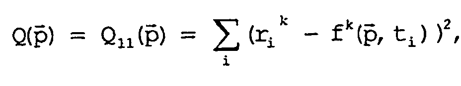
Ein weiteres Beispiel für die Definition der Norm Q(
Zur Schätzung der Parameterwerte wird im Zusammenhang mit
der zweiten Ausführungsform vorzugsweise eine Norm Q(
Ein Beispiel für die Definition der Norm Q( 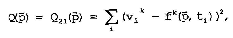
Ein weiteres Beispiel für die Definition der Norm Q(
Zur Schätzung der Parameterwerte wird im Zusammenhang mit
der dritten Ausführungsform vorzugsweise eine Norm Q(
Ein Beispiel für die Definition der Norm Q( 
Ein weiteres Beispiel für die Definition der Norm Q(
Wie erwähnt, werden die Parameterwerte für die im Vektor
In diesem Zusammenhang wird bevorzugt, dass die Parameterwerte
für die im Vektor
Ein geeignetes Optimierungsverfahren, das beispielsweise
angewendet werden kann, wenn die Norm Q(


hat, ist die dem Fachmann bekannte Methode der kleinsten
Fehlerquadrate.A suitable optimization method that can be used, for example, if the standard Q (
has, is known to those skilled method of least squares.
In einigen Fällen kann zur Vereinfachung angenommen werden,
dass die relative Beschleunigung a des Zielobjekts
konstant ist und/oder dass der Beschleunigungsvektor ä
parallel zum Geschwindigkeitsvektor
Wenn die geschätzten Parameterwerte für die im Vektor
Aus den geschätzten Parameterwerten der im Vektor 
Es ist ebenfalls möglich, aus den geschätzten Parameterwerten
der im Vektor
Auch der Betrag der relativen Momentanradialgeschwindigkeit
des Zielobjekts kann aus den geschätzten Parameterwerten
der im Vektor
Wenn ein Winkel β zwischen einer Normalen des Objekts und
dem Vektor des Zielobjektabstands r gleich dem Winkel α
zwischen den Vektoren der relativen Geschwindigkeit v des
Zielobjekts und der relativen Radialgeschwindigkeit vr
des Zielobjekts beziehungsweise zwischen den Vektoren der
relativen Beschleunigung a des Zielobjekts und der relativen
Radialbeschleunigung ar des Zielobjekts ist, gilt
für die auf das Objekt bezogenen Normalkomponenten vn=v,
an=a und x=rcos(α). In diesem Fall kann der Zeitpunkt t1
einer gegebenenfalls stattfindenden Kollision aus den
geschätzten Parameterwerten der im Vektor
Weiterhin kann vorgesehen sein, dass unter Verwendung der
geschätzten Parameterwerte der im Vektor
definiert wird. Das Fehlermaß e(
is defined. The error measure e (
Bezüglich der bei der erfindungsgemäßen Vorrichtung vorgesehenen Mittel wird darauf hingewiesen, dass diese Mittel vom Fachmann problemlos durch geeignete Hardware und Software oder andere Schaltungen verwirklicht werden können.Regarding provided in the device according to the invention Medium is advised that this Means by the expert without problems by suitable hardware and software or other circuits can.
Die Erfindung wird nachfolgend anhand der zugehörigen Zeichnungen noch näher erläutert.The invention is described below with reference to the associated Drawings explained in more detail.
Es zeigen:
- Figur 1
- eine geometrische Darstellung des Objekts und des Zielobjekts; und
- Figur 2
- eine Darstellung der verschiedenen Parameter.
- FIG. 1
- a geometric representation of the object and the target object; and
- FIG. 2
- a representation of the various parameters.
In Figur 1 ist ein Objekt in Form eines ersten Fahrzeugs
insgesamt mit dem Bezugszeichen 10 versehen. An dem ersten
Fahrzeug 10 ist eine Sensorik 11 angeordnet. Die
Normale zum Frontbereich des ersten Kraftfahrzeuges 10
ist mit 13 bezeichnet. Ein Zielobjekt in Form eines zweiten
Fahrzeugs ist insgesamt mit dem Bezugszeichen 12
versehen. Insgesamt zeigt Figur 1 den Fall einer Vorbeifahrt,
das heißt, es findet keine Kollision statt. Der
Abstand zwischen dem ersten Fahrzeug 10 und dem zweiten
Fahrzeug 12 ist durch einen Vektor r gekennzeichnet,
dessen zum Frontbereich des ersten Fahrzeugs 10 normale
Komponente mit x gekennzeichnet ist. Zwischen den Vektoren
r und x wird ein Winkel β eingeschlossen. Wenn sich
das zweite Fahrzeug 12 am Punkt P befindet, beträgt der
Versatz zwischen dem ersten Fahrzeug 10 und dem zweiten
Fahrzeug 12 Δy, wobei der anfängliche Abstand zwischen
dem Punkt P und dem zweiten Fahrzeug 12 durch den Vektor
z gekennzeichnet ist.FIG. 1 shows an object in the form of a first vehicle
total provided with the
Anhand des Versatzes Δy kann entweder eine Vorbeifahrt oder eine bevorstehende Kollision detektiert werden. Der Versatz Δy wird in diesem Fall in der horizontalen Ebene (Azimut) angenommen. Hierbei ist es zweckmäßig, mit einem geringen Öffnungswinkel in der vertikalen Richtung (Elevation) zu messen. Will man beispielsweise die Höhe des Zielobjektes, das heißt den Versatz in vertikaler Richtung, bestimmen, so ist ein geringer Öffnungswinkel im Azimut geeignet. Prinzipiell ist die Messung des Versatzes auch in einer zur horizontalen oder vertikalen Ebene beliebig geneigten Ebene mit entsprechend flachem Antennendiagramm möglich. Misst man den Versatz in zwei orthogonal zueinander stehenden Ebenen (z.B. Elevation und Azimut), so sind mit dem Zielobjektabstand r die Zielkoordinaten im überwachten Raum eindeutig bestimmt.Based on the offset Δy can either pass by or an impending collision can be detected. Of the Offset Δy in this case is in the horizontal plane (Azimuth) assumed. It is useful with a small opening angle in the vertical direction (elevation) to eat. For example, if you want the height of the Target object, that is the offset in the vertical direction, determine, so is a small opening angle in Azimuth suitable. In principle, the measurement of the offset also in a horizontal or vertical plane arbitrarily inclined plane with correspondingly flat antenna diagram possible. Measure the offset in two orthogonal planes (e.g., elevation and Azimuth), the target coordinates r are the target coordinates clearly determined in the monitored room.
In Figur 2 sind einige wichtige Parameter angegeben. Die
Anfangsposition des ersten Fahrzeugs 10 und des zweiten
Fahrzeugs 12 entspricht dabei der von Figur 1. In Figur 2
zeigen die Vektorpfeile das kinematische Verhalten des
zweiten Fahrzeugs 12. In der Praxis bewegen sich jedoch
in der Regel sowohl das erste Fahrzeug 10 als auch das
zweite Fahrzeug 12, oder das Zielobjekt ist nicht durch
ein zweites Fahrzeug, sondern durch ein feststehendes
Zielobjekt gebildet. Daher wird hier wie im Vorhergehenden
von relativen Größen gesprochen.In Figure 2, some important parameters are given. The
Initial position of the
Die Vektoren vr und ar geben die relative Radialgeschwindigkeit
beziehungsweise die relative Radialbeschleunigung
des zweiten Fahrzeugs 12 an. Die Vektoren v und a geben
die relative Geschwindigkeit und die relative Beschleunigung
des zweiten Fahrzeugs 12 an, wobei zwischen den
Vektoren vr und v beziehungsweise ar und a ein Winkel α
eingeschlossen wird. Die zu den radialen Komponenten
senkrechten tangentialen Komponenten der relativen Radialgeschwindigkeit
vr beziehungsweise der relativen
Radialbeschleunigung ar des zweiten Fahrzeugs sind mit vt
beziehungsweise at angegeben, wobei durch die Vektoren vt
und at beziehungsweise v und a der Punkt P definiert
wird.The vectors v r and a r indicate the relative radial velocity and the relative radial acceleration of the
Die vorhergehende Beschreibung der Ausführungsbeispiele gemäß der vorliegenden Erfindung dient nur zu illustrativen Zwecken und nicht zum Zwecke der Beschränkung der Erfindung. Im Rahmen der Erfindung sind verschiedene Änderungen und Modifikationen möglich, ohne den Umfang der Erfindung sowie ihre Äquivalente zu verlassen, die durch die nachfolgenden Ansprüche definiert sind.The preceding description of the embodiments in accordance with the present invention is illustrative only Purposes and not for the purpose of limiting the Invention. Within the scope of the invention are various Changes and modifications possible without the scope to leave the invention and its equivalents, the are defined by the following claims.
Claims (16)
- Method for indication of parameter values which relate to the relative kinematic behaviour of an object (10), in particular of a first vehicle (10), and of a target object (12), in particular of a second vehicle (12), in which case a statement can be made on the basis of the parameter values as to whether the object (10) and the target object (12) are predicted to collide, having the following steps:where r0 is the target object distance in the first measurement, v0 is the relative initial velocity of the target object (12) in the first measurement, a is the relative acceleration of the target object (12), t is the time and α0 is the angle between the vectors of the relative velocity v of the target object (12) and the relative radial velocity vr of the target object (12), or the angle between the vectors of the relative acceleration a of the target object (12) and the relative radial acceleration ar of the target object (12) in the first measurement.a) provision of a sensor system (11) on the object (10), with the sensor system (11) being provided in order to transmit and to receive signals in order to record measured values ri, vr,i for the target object distance r and/or for the relative radial velocity vr of the target object (12),b) recording of measured values ri, vr,i, andc) evaluation of the recorded measured values ri, vr,i on the basis of the signals received by a receiver, characterized in that relative radial velocities vr,i of the target object (12) are measured at different times ti in order to record measured values ri, vr,i and in that the relative radial velocity vr of the target object (12) is described using the relationship:

- Method according to Claim 1, characterized in that the parameter values relate to at least one or more of the following parameters: the relative acceleration a of the target object (12), the relative radial acceleration ar of the target object (12), the relative velocity v of the target object (12), the relative radial velocity vr of the target object (12), the offset Δy between the object (10) and the target object (12), the angle α between the vectors of the relative velocity v of the target object (12) and the relative radial velocity vr of the target object (12), or between the vectors of the relative acceleration a of the target object (12) and the relative radial acceleration ar of the target object (12).
- Method according to Claim 1 or Claim 2, characterized in that a vector
p which contains at least some of the sought parameters is provided, with the vectorp being in the form: - Method according to one of the preceding claims, characterized in that target object distances ri are measured at different times ti in the step b), and in that the target object distance r is described by the relationship:
- Method according to one of the preceding claims, characterized in that target object distances ri and relative radial velocities vr,i are measured at different times ti in step b), and in that the relative radial velocity vr of the target object (12) is described by the relationship:where r0 is the target object distance in the first measurement, v0 is the relative initial velocity of the target object (12) in the first measurement, a is the relative acceleration of the target object (12), t is the time and α0 is the angle between the vectors of the relative velocity v of the target object (12) and the relative radial velocity vr of the target object (12), or the angle between the vectors of the relative acceleration a of the target object (12) and the relative radial acceleration ar of the target object (12) in the first measurement.

- Method according to one of the preceding claims, characterized in that a norm Q(
p ) is defined as follows in order to estimate the parameter values: - Method according to Claim 3 or one of Claims 4 to 6, to the extent that these are dependent on Claim 3 characterized in that the parameter values for the parameters contained in the vector
p are estimated on the basis of the measured values. - Method according to Claim 6, characterized in that the parameter values for the parameters contained in the vector
p are estimated on the basis of the times ti and the measured values ri for the target object distances and/or the measured values vi for the relative radial velocities using an optimization method, by determining the minimum of the norm Q(p ). - Apparatus for emitting parameter values which relate to the relative kinematic behaviour of an object (10), in particular of a first vehicle (10), and of a target object (12), in particular of a second vehicle (12), in which case a statement can be made on the basis of the parameter values as to whether the object (10) and the target object (12) are predicted to collide, having:characterized in that the sensor system (11) records measured values for relative radial velocities vr,i of the target object (12) at different times ti, and in that the means describe the relative radial velocity vr of the target object (12) using the relationship:a sensor system (11) which is arranged on the object (10) with the sensor system (11) being provided in order to transmit and to receive signals in order to record measured values ri, vr,i for the target object distance r and/or for the relative radial velocity vr of the target object (12), andmeans for evaluation of the measured values ri, vr,i recorded by the sensor system and for emitting parameter values, in which case the evaluation can be carried out on the basis of the signals which are received by only one of the receivers associated with the sensor system (11),where r0 is the target object distance in the first measurement, v0 is the relative initial velocity of the target object (12) in the first measurement, a is the relative acceleration of the target object (12), t is the time and α0 is the angle between the vectors of the relative velocity v of the target object (12) and the relative radial velocity vr of the target object (12), or the angle between the vectors of the relative acceleration a of the target object (12) and the relative radial acceleration ar of the target object (12) in the first measurement.

- Apparatus according to Claim 9, characterized in that the parameter values relate to at least one or more of the following parameters: the relative acceleration a of the target object (12), the relative radial acceleration ar of the target object, the relative velocity v of the target object (12), the relative radial velocity vr of the target object (12), the offset Δy between the object (10) and the target object (12), the angle α between the vectors of the relative velocity v of the target object (12) and the relative radial velocity vr of the target object (12), or between the vectors of the relative acceleration a of the target object (12) and the relative radial acceleration ar of the target object (12).
- Apparatus according to Claim 9 or Claim 10, characterized in that a vector
p which contains at least some of the sought parameters is provided for evaluation of the measured values ri, vr,i recorded by the sensor system (11), with the vectorp being in the form - Apparatus according to one of Claims 9 to 11, characterized in that the sensor system (11) records measured values for target object distances ri at different times ti, and in that the means describe the target object distance r using the relationship:
- Apparatus according to one of Claims 9 to 12, characterized in that the sensor system (11) records measured values for target object distances ri and measured values for relative radial velocities vr,i at different times ti, and in that the means describe the relative radial velocity vr of the target object (12) using the relationship:where r0 is the target object distance in the first measurement, v0 is the relative initial velocity of the target object (12) in the first measurement, a is the relative acceleration of the target object (12), t is the time and α0 is the angle between the vectors of the relative velocity v of the target object (12) and the relative radial velocity vr of the target object (12), or the angle between the vectors of the relative acceleration a of the target object (12) and the relative radial acceleration ar of the target object (12) in the first measurement.

- Apparatus according to one of Claims 9 to 13, characterized in that the means for estimation of the parameter values define a norm Q(
p ): - Apparatus according to Claim 11, characterized in that the means estimate the parameter values for the parameters contained in the vector
p on the basis of the measured values. - Apparatus according to Claim 14, characterized in that the means estimate the parameter values for the parameters contained in the vector
p on the basis of the times ti and the measured values ri for the target object distances and/or the measured values vi for the relative radial velocities using an optimization method, by determining the minimum of the norm Q(p ).
Applications Claiming Priority (3)
| Application Number | Priority Date | Filing Date | Title |
|---|---|---|---|
| DE10100413 | 2001-01-08 | ||
| DE10100413A DE10100413A1 (en) | 2001-01-08 | 2001-01-08 | Method and device for estimating movement parameters of targets |
| PCT/DE2001/004912 WO2002054369A1 (en) | 2001-01-08 | 2001-12-22 | Method and device for estimating movement parameters of targets |
Publications (2)
| Publication Number | Publication Date |
|---|---|
| EP1352375A1 EP1352375A1 (en) | 2003-10-15 |
| EP1352375B1 true EP1352375B1 (en) | 2005-08-24 |
Family
ID=7669893
Family Applications (1)
| Application Number | Title | Priority Date | Filing Date |
|---|---|---|---|
| EP01991684A Expired - Lifetime EP1352375B1 (en) | 2001-01-08 | 2001-12-22 | Method and device for estimating movement parameters of targets |
Country Status (6)
| Country | Link |
|---|---|
| US (1) | US6785631B2 (en) |
| EP (1) | EP1352375B1 (en) |
| JP (1) | JP4044844B2 (en) |
| DE (2) | DE10100413A1 (en) |
| ES (1) | ES2248411T3 (en) |
| WO (1) | WO2002054369A1 (en) |
Families Citing this family (7)
| Publication number | Priority date | Publication date | Assignee | Title |
|---|---|---|---|---|
| DE102007047716A1 (en) * | 2007-10-05 | 2009-04-09 | Robert Bosch Gmbh | Sensor device for capacitive distance determination |
| DE102007058242A1 (en) * | 2007-12-04 | 2009-06-10 | Robert Bosch Gmbh | Method for measuring transverse movements in a driver assistance system |
| CA2910296A1 (en) * | 2014-12-12 | 2016-06-12 | Atlantic Inertial Systems Limited (HSC) | Collision detection system |
| DE102017204496A1 (en) | 2017-03-17 | 2018-09-20 | Robert Bosch Gmbh | Method and radar device for determining radial relative acceleration of at least one target |
| DE102017204495A1 (en) * | 2017-03-17 | 2018-09-20 | Robert Bosch Gmbh | Method and device for determining transverse relative velocity components of radar targets |
| US20190187267A1 (en) * | 2017-12-20 | 2019-06-20 | Nxp B.V. | True velocity vector estimation |
| DE102018211240A1 (en) * | 2018-07-07 | 2020-01-09 | Robert Bosch Gmbh | Method for classifying an object's relevance |
Family Cites Families (7)
| Publication number | Priority date | Publication date | Assignee | Title |
|---|---|---|---|---|
| US5983161A (en) * | 1993-08-11 | 1999-11-09 | Lemelson; Jerome H. | GPS vehicle collision avoidance warning and control system and method |
| JP3186401B2 (en) | 1994-02-10 | 2001-07-11 | 三菱電機株式会社 | Vehicle distance data processing device |
| JPH08124100A (en) | 1994-10-28 | 1996-05-17 | Nikon Corp | Monitoring device for distance between vehicles |
| US6014601A (en) * | 1997-01-07 | 2000-01-11 | J. Martin Gustafson | Driver alert system |
| DE19749086C1 (en) * | 1997-11-06 | 1999-08-12 | Daimler Chrysler Ag | Device for determining data indicating the course of the lane |
| JP3381778B2 (en) | 1998-08-05 | 2003-03-04 | 三菱自動車工業株式会社 | Vehicle running control method |
| DE19910590A1 (en) * | 1999-03-10 | 2000-09-14 | Volkswagen Ag | Distance control method and device for a vehicle |
-
2001
- 2001-01-08 DE DE10100413A patent/DE10100413A1/en not_active Withdrawn
- 2001-12-22 DE DE50107229T patent/DE50107229D1/en not_active Expired - Fee Related
- 2001-12-22 US US10/221,082 patent/US6785631B2/en not_active Expired - Fee Related
- 2001-12-22 ES ES01991684T patent/ES2248411T3/en not_active Expired - Lifetime
- 2001-12-22 WO PCT/DE2001/004912 patent/WO2002054369A1/en active IP Right Grant
- 2001-12-22 EP EP01991684A patent/EP1352375B1/en not_active Expired - Lifetime
- 2001-12-22 JP JP2002555392A patent/JP4044844B2/en not_active Expired - Fee Related
Also Published As
| Publication number | Publication date |
|---|---|
| DE50107229D1 (en) | 2005-09-29 |
| US6785631B2 (en) | 2004-08-31 |
| JP2004517420A (en) | 2004-06-10 |
| ES2248411T3 (en) | 2006-03-16 |
| US20030163280A1 (en) | 2003-08-28 |
| DE10100413A1 (en) | 2002-07-11 |
| JP4044844B2 (en) | 2008-02-06 |
| EP1352375A1 (en) | 2003-10-15 |
| WO2002054369A1 (en) | 2002-07-11 |
Similar Documents
| Publication | Publication Date | Title |
|---|---|---|
| DE102009053283B4 (en) | Method and device for recognizing a parking space | |
| EP2140287B1 (en) | Driver assistance system and method for determining the plausibility of objects | |
| EP0987563B1 (en) | Method for determining the distance separating an object and a movable installation, in particular a motorised vehicle | |
| DE102013215117A1 (en) | Object determination by means of radar sensor | |
| EP2793045A1 (en) | Method for testing an environment detection system of a vehicle | |
| EP3714286B1 (en) | Method and device for ascertaining an installation angle between a roadway on which a vehicle travels and a detection direction of a measurement or radar sensor | |
| DE102012200139A1 (en) | Method and device for wheel-independent speed measurement in a vehicle | |
| DE102006045115A1 (en) | System and method for target tracking using sensor fusion | |
| DE102018104243B3 (en) | Method and system for detecting parking spaces suitable for a vehicle | |
| EP3740784A1 (en) | Method and device for detecting critical transverse movements | |
| EP2339374A2 (en) | Method for recording objects and transducer assembly for same | |
| EP1352375B1 (en) | Method and device for estimating movement parameters of targets | |
| DE102014209723A1 (en) | Determination of an indicator of blindness of a radar sensor | |
| WO2019162317A1 (en) | Method for generating sensor data for safety-critical automobile control devices | |
| DE102018221448A1 (en) | Procedure for determining visibility | |
| EP1488254B1 (en) | Method for determining the relative speed of an object | |
| DE102014008732A1 (en) | Method and device for monitoring a radar value of a radar system and traffic monitoring system | |
| DE10342128A1 (en) | Method and distance detection device for determining the distance between at least one sensor device and an object | |
| DE10160299A1 (en) | Method and system for detecting at least one object | |
| EP3740781A1 (en) | Method and device for checking the plausibility of a transverse movement | |
| WO2022228738A1 (en) | Orientation-based position determination for rail vehicles | |
| DE102019128023B4 (en) | Method for classifying the height of an object by a driving assistance system | |
| EP3658953B1 (en) | Device and method for detecting the height of an object | |
| DE102020121108A1 (en) | Method for detecting road users in the vicinity of a vehicle based on measurements from a radar sensor by identifying interference detections, and computing device | |
| DE102007008853A1 (en) | Illusion field detecting method for e.g. global positioning system receiver, involves providing reference periodic information, and comparing reference periodic information with periodic information contained in navigation signals |
Legal Events
| Date | Code | Title | Description |
|---|---|---|---|
| PUAI | Public reference made under article 153(3) epc to a published international application that has entered the european phase |
Free format text: ORIGINAL CODE: 0009012 |
|
| 17P | Request for examination filed |
Effective date: 20030808 |
|
| AK | Designated contracting states |
Kind code of ref document: A1 Designated state(s): AT BE CH CY DE DK ES FI FR GB GR IE IT LI LU MC NL PT SE TR |
|
| AX | Request for extension of the european patent |
Extension state: AL LT LV MK RO SI |
|
| 17Q | First examination report despatched |
Effective date: 20040305 |
|
| RBV | Designated contracting states (corrected) |
Designated state(s): DE ES FR GB IT SE |
|
| GRAP | Despatch of communication of intention to grant a patent |
Free format text: ORIGINAL CODE: EPIDOSNIGR1 |
|
| GRAS | Grant fee paid |
Free format text: ORIGINAL CODE: EPIDOSNIGR3 |
|
| GRAA | (expected) grant |
Free format text: ORIGINAL CODE: 0009210 |
|
| AK | Designated contracting states |
Kind code of ref document: B1 Designated state(s): DE ES FR GB IT SE |
|
| REG | Reference to a national code |
Ref country code: GB Ref legal event code: FG4D Free format text: NOT ENGLISH |
|
| REF | Corresponds to: |
Ref document number: 50107229 Country of ref document: DE Date of ref document: 20050929 Kind code of ref document: P |
|
| REG | Reference to a national code |
Ref country code: SE Ref legal event code: TRGR |
|
| GBT | Gb: translation of ep patent filed (gb section 77(6)(a)/1977) |
Effective date: 20051212 |
|
| REG | Reference to a national code |
Ref country code: ES Ref legal event code: FG2A Ref document number: 2248411 Country of ref document: ES Kind code of ref document: T3 |
|
| ET | Fr: translation filed | ||
| PLBE | No opposition filed within time limit |
Free format text: ORIGINAL CODE: 0009261 |
|
| STAA | Information on the status of an ep patent application or granted ep patent |
Free format text: STATUS: NO OPPOSITION FILED WITHIN TIME LIMIT |
|
| 26N | No opposition filed |
Effective date: 20060526 |
|
| PGFP | Annual fee paid to national office [announced via postgrant information from national office to epo] |
Ref country code: ES Payment date: 20071220 Year of fee payment: 7 |
|
| PGFP | Annual fee paid to national office [announced via postgrant information from national office to epo] |
Ref country code: IT Payment date: 20071220 Year of fee payment: 7 |
|
| PGFP | Annual fee paid to national office [announced via postgrant information from national office to epo] |
Ref country code: SE Payment date: 20071220 Year of fee payment: 7 |
|
| PGFP | Annual fee paid to national office [announced via postgrant information from national office to epo] |
Ref country code: GB Payment date: 20071220 Year of fee payment: 7 |
|
| PGFP | Annual fee paid to national office [announced via postgrant information from national office to epo] |
Ref country code: DE Payment date: 20080226 Year of fee payment: 7 |
|
| PGFP | Annual fee paid to national office [announced via postgrant information from national office to epo] |
Ref country code: FR Payment date: 20071214 Year of fee payment: 7 |
|
| EUG | Se: european patent has lapsed | ||
| GBPC | Gb: european patent ceased through non-payment of renewal fee |
Effective date: 20081222 |
|
| REG | Reference to a national code |
Ref country code: FR Ref legal event code: ST Effective date: 20090831 |
|
| PG25 | Lapsed in a contracting state [announced via postgrant information from national office to epo] |
Ref country code: DE Free format text: LAPSE BECAUSE OF NON-PAYMENT OF DUE FEES Effective date: 20090701 |
|
| PG25 | Lapsed in a contracting state [announced via postgrant information from national office to epo] |
Ref country code: GB Free format text: LAPSE BECAUSE OF NON-PAYMENT OF DUE FEES Effective date: 20081222 |
|
| REG | Reference to a national code |
Ref country code: ES Ref legal event code: FD2A Effective date: 20081223 |
|
| PG25 | Lapsed in a contracting state [announced via postgrant information from national office to epo] |
Ref country code: FR Free format text: LAPSE BECAUSE OF NON-PAYMENT OF DUE FEES Effective date: 20081231 Ref country code: ES Free format text: LAPSE BECAUSE OF NON-PAYMENT OF DUE FEES Effective date: 20081223 |
|
| PG25 | Lapsed in a contracting state [announced via postgrant information from national office to epo] |
Ref country code: SE Free format text: LAPSE BECAUSE OF NON-PAYMENT OF DUE FEES Effective date: 20081223 |
|
| PG25 | Lapsed in a contracting state [announced via postgrant information from national office to epo] |
Ref country code: IT Free format text: LAPSE BECAUSE OF NON-PAYMENT OF DUE FEES Effective date: 20081222 |