EP1351550A1 - Verfahren zur Anpassung einer Signalverstärkung in einem Hörgerät sowie ein Hörgerät - Google Patents
Verfahren zur Anpassung einer Signalverstärkung in einem Hörgerät sowie ein Hörgerät Download PDFInfo
- Publication number
- EP1351550A1 EP1351550A1 EP02020202A EP02020202A EP1351550A1 EP 1351550 A1 EP1351550 A1 EP 1351550A1 EP 02020202 A EP02020202 A EP 02020202A EP 02020202 A EP02020202 A EP 02020202A EP 1351550 A1 EP1351550 A1 EP 1351550A1
- Authority
- EP
- European Patent Office
- Prior art keywords
- input signal
- level
- signal
- min2
- min1
- Prior art date
- Legal status (The legal status is an assumption and is not a legal conclusion. Google has not performed a legal analysis and makes no representation as to the accuracy of the status listed.)
- Granted
Links
Images

Classifications
-
- H—ELECTRICITY
- H04—ELECTRIC COMMUNICATION TECHNIQUE
- H04R—LOUDSPEAKERS, MICROPHONES, GRAMOPHONE PICK-UPS OR LIKE ACOUSTIC ELECTROMECHANICAL TRANSDUCERS; ELECTRIC HEARING AIDS; PUBLIC ADDRESS SYSTEMS
- H04R25/00—Electric hearing aids
- H04R25/35—Electric hearing aids using translation techniques
- H04R25/356—Amplitude, e.g. amplitude shift or compression
-
- H—ELECTRICITY
- H03—ELECTRONIC CIRCUITRY
- H03G—CONTROL OF AMPLIFICATION
- H03G7/00—Volume compression or expansion in amplifiers
-
- H—ELECTRICITY
- H03—ELECTRONIC CIRCUITRY
- H03G—CONTROL OF AMPLIFICATION
- H03G7/00—Volume compression or expansion in amplifiers
- H03G7/007—Volume compression or expansion in amplifiers of digital or coded signals
-
- H—ELECTRICITY
- H04—ELECTRIC COMMUNICATION TECHNIQUE
- H04R—LOUDSPEAKERS, MICROPHONES, GRAMOPHONE PICK-UPS OR LIKE ACOUSTIC ELECTROMECHANICAL TRANSDUCERS; ELECTRIC HEARING AIDS; PUBLIC ADDRESS SYSTEMS
- H04R25/00—Electric hearing aids
- H04R25/50—Customised settings for obtaining desired overall acoustical characteristics
- H04R25/505—Customised settings for obtaining desired overall acoustical characteristics using digital signal processing
Definitions
- the present invention relates to a method for Adaptation of a signal amplification in a hearing aid, in which with the help of an electro-acoustic transducer Input signal for a signal processing unit generated and in which an output signal over the Signal amplification is determined, and a hearing aid.
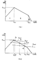
- FIG. 1 A known gain curve is shown in FIG. 1, where the gain G is represented as a function of the level S of the input signal. Both the gain G and the level S of the input signal are given in decibels (dB). From the course shown in Fig. 1 for the gain G are three areas I, II and III identifiable, of which in the area I said noise barrier, in the area II of the normal operating range and in area III, an output level limitation is made. The slope of the course of the gain G in the region II corresponds to a compression required to compensate for a hearing loss. In contrast, it is avoided by the course of the gain G in the region I that ambient noise, which usually do not contain information for the hearing aid wearer, are amplified according to the respective level.
- ambient noise which usually do not contain information for the hearing aid wearer
- first knee point S KP1 a first limit value between the regions I and II, which is referred to below as the first knee point S KP1 . If the value of the first knee point S KP1 is set too high, the intelligibility of spoken words in very quiet environments is reduced. If, on the other hand, the value of the first knee point S KP1 is chosen too low, then on the other hand disturbing noises are insufficiently suppressed.
- the upper limit hereinafter referred to as the second knee point S KP2 , defined between the areas II and III, wherein input signals higher level than the second knee point S KP2 be limited, since it is assumed that input signals with higher values the second knee point S KP2 associated with the applied at this input level gain, from which the output level results, are perceived as painful for the hearing aid wearer.
- the above-mentioned one-path system is a so-called two-path system with two time constants are used basically the same disadvantage exists.
- the known Method is based on two time constants, namely on a long time constant of typically several Seconds and a shorter time constant of typically several tens of milliseconds. While over the long time constant the middle amplification is set via the shorter time constant the actual syllable compression. Both paths will be so that in the end the fast path, with the shorter time constants, the slower path that the determined actual operating point, is superimposed. The Connection takes place via the through the slow path determined operating point.
- FIG. 1 A possible course of a signal amplification for such a two-path system is shown in FIG. On the abscissa and the ordinate again the same quantities in the same units as in Fig. 1 are entered. While G slow is the path of the slow path which defines the actual operating point A 1 , A 2 or A 3 , G fast1 or G fast2 or G fast3 designates the fast path in which the syllable compression is performed ,
- a single-path system can be either syllable compression or an automatic volume control (AVC Automatic Volume Control), but not both.
- AVC Automatic Volume Control automatic Volume Control
- the well-known one-way system was developed by Brian C. J. Moore in "Perceptual consequences of cochlear damage" (ISBN 0 19 852330 0, pages 179 to 189) described in detail.
- the two-path system also benefits from a reduced gain below the first knee point S KP1 , as long as the input level is low for a longer duration. With short pauses in speech, the known two-path system can therefore not meaningfully reduce the gain. If, on the other hand, another, fixed knee point with reduced amplification is introduced at smaller input levels in the fast path of a two-path system, then the knee-point level is set incorrectly for very quiet or very loud signals, ie the voice information is no longer sufficiently amplified, or else it is Noise is amplified too much.
- the known two-path systems were by Michael Stone et. al. in the article "Comparison of different forms of compression using waerable digital hearing aids" (J. Acoust Soc., 106 (6), December 1999, pages 3603 to 3609) described in detail.
- the present invention is therefore the task to provide a method in which the above mentioned disadvantages do not occur.
- the invention has the following advantages: minimum input levels depending on the mean level of the input signal is adaptively adjusted changing situations, for example, in a changing soundscape or a changing one Volume of a speaker may consist of bill carried. As a result, an improved Noise reduction and an increase in hearing reached.
- the inventive method has the consequence that unwanted background noise much better be suppressed than this in a known static System is the case.
- SNR signal-to-noise ratio
- spectral subtraction but it is about an evaluation of the Long-term behavior of the input signal level, optionally in certain frequency bands, one Noise suppression realized.
- SNR signal-to-noise ratio
- Fig. 3 is a block diagram of a hearing aid shown, which consists of an electro-acoustic transducer 1, by means of which acoustic signals into electrical signals, hereinafter referred to as input s, converted be a signal processing unit 2, the Input signal s is acted upon, as well as a Speaker unit 3, which in the hearing aid industry too is referred to as a listener exists.
- an electro-acoustic transducer 1 by means of which acoustic signals into electrical signals, hereinafter referred to as input s, converted be a signal processing unit 2, the Input signal s is acted upon, as well as a Speaker unit 3, which in the hearing aid industry too is referred to as a listener exists.
- Hearing aid related to all possible applications understood better hearing, regardless of whether the devices used here partially or be fully inserted into the ear canal - like this in so-called BtE (behind-the-ear) or CIC (Completely-in-the-Canal) hearing aids the case is - or whether the devices used even in the human Body are implanted or are.
- the signals preferably processed in digital form, so that in addition to the illustrated processing units Analog / digital converter or digital / analog converter to be provided. Furthermore, the processing of the Signals in the embodiment shown in Fig. 3 in the Frequency range.
- An analogous embodiment results in an embodiment in which the signals in Time range are processed. The transfer of the in Fig. 3 illustrated embodiments in a form in the all signals are present in the time domain and in this can be processed by a specialist Knowledge in signal processing in a simple manner realize.
- Fig. 3 shows - the input signal s a Transformation unit DFT applied, in which the Level S is determined in function of the frequency.
- the Transformation unit DFT is preferably the case called Fast Fourier transformation used.
- the input signal s becomes both a first input of a multiplier unit 5 and a Calculation unit 10, in which the signal level S For example, determined as RMS (Root Mean Square) level is charged.
- the output signal of Calculation unit 10 is a gain unit GM and whose output signal is a second input of Multiplier unit 5 is applied, so that the Output of the multiplier unit 5, i.
- the level O of the output signal, by a in the amplifier unit GM implemented amplifier model is influenced, which is in the will be explained in detail below.
- more Processing steps applied in operation units 4 become.
- Such a further processing step can for example, limiting the level of the Output signal to a maximum value.
- the output o the Back transformation unit IDFT of the speaker unit 3 acted in the a corresponding acoustic signal is produced.
- the speaker unit 3 can be omitted.
- the acoustic Stimulation is then done in a different way, namely by the output o in another, by the human Body perceivable signal is transformed.
- Fig. 4 shows a solid line a gain curve of a slow path in function of the level S of the input signal s.
- the average level S m of the input signal s is determined with a time constant of a few seconds.
- An instantaneous mean value for the level S m of the input signal s defines a current operating point, as illustrated for example with two different operating points A 1 and A 2 in FIG. 4.
- a specific syllable compression then becomes effective via a second, fast path, as indicated by the amplification progressions G 1 and G 2 shown in dashed lines.
- gain gradients G 1 and G 2 for the syllable compression fall the gain gradients G 1 and G below the minimum input signal level S min1 or S min2 preferably linearly, in other words, signal level, which are further below the minimum input level S min1 and S min2 than others, less amplified.
- the gain curves G 1 and G 2 preferably without discontinuity, are linked to the corresponding progressions in the compression regions.
- the syllable compression has a piecewise linear progression over the entire level range of the input signal s in one embodiment of the invention.
- a maximum input signal level S max1 or S max2 is determined for each gain curve G 1 or G 2 , above which a signal limitation is provided.
- the maximum input signal level S max1 or S max2 is in this case a predefinable difference value ⁇ max above the instantaneous mean level S m1 or S m2 of the input signal s.
- the gain curve will have a different course for higher input signal levels S than the maximum input signal levels S max1 and S max2, respectively , than for lower input signal levels S than the maximum input signal levels S max1 and S max2, respectively . According to the gain curves G 1 and G 2 for the syllable compression shown in FIG.
- the gain curves G 1 and G 2 above the maximum input signal level S max1 and S max2 fall linearly, in other words, signal levels, which are further above the maximum input level S max1 or S max2 than others, less amplified.
- the gain curves G 1 and G 2 preferably without discontinuity, are linked to the corresponding progressions in the compression regions.
- the syllable compression has a piecewise linear progression over the entire level range of the input signal s in one embodiment.
- the human speech has a dynamic range of approximately -15 to +18 dB (decibels) around the respective mean level S m , where in a quiet environment, ie in low ambient noise, the average level is about 60 to 65 dB. In noisy environment, the average level can rise to about 80 dB.
- the first predefinable difference value ⁇ min is preferably selected to be equal to 15 dB
- the second predefinable difference value ⁇ max is preferably selected to be equal to 18 dB.
- the above statements in connection with FIG. 4 refer to a two-path system in which the minimum, possibly also the maximum Level Sm of the input signal s are adaptively set.
- the invention is a one-way system transferable, in which the single knee point, i. of the single minimum input signal level, adaptive in Dependence on the mean level of the input signal is set.
- Variants may be the estimate of the mean Level either in a wide frequency band or several frequency bands can be defined it is conceivable that in each of the Frequency bands individual knee points, i. minimal and possibly maximum input signal level, below Application of an individual local statistics determined become.
- the gain curve below the minimum input signal level of the slow path is chosen differently compared to the Amplification course of the fast path. So it is conceivable that in one path a linear gain curve and in other a compressive or an expansive Amplification course is provided.
Landscapes
- Health & Medical Sciences (AREA)
- General Health & Medical Sciences (AREA)
- Neurosurgery (AREA)
- Otolaryngology (AREA)
- Physics & Mathematics (AREA)
- Engineering & Computer Science (AREA)
- Acoustics & Sound (AREA)
- Signal Processing (AREA)
- Tone Control, Compression And Expansion, Limiting Amplitude (AREA)
Abstract
Description
- Fig. 1
- einen bekannten, stückweise linearen Verstärkungsverlauf bei einem Einpfad-System,
- Fig. 2
- einen bekannten Verstärkungsverlauf bei einem Zweipfad-System, bestehend aus einem langsamen und einem schnellen Pfad,
- Fig. 3
- ein Blockschaltbild eines Hörgerätes und
- Fig. 4
- einen erfindungsgemässen Verstärkungsverlauf bei einem Zweipfad-System.
Claims (18)
- Verfahren zur Anpassung einer Signalverstärkung (G) in einem Hörgerät, in dem mit Hilfe eines elektro-akustischen Wandlers (1) ein Eingangssignal (s) für eine Signalverarbeitungseinheit (2) erzeugt wird und in dem ein Ausgangssignal (o) über die Signalverstärkung (G) bestimmt wird, wobei das Verfahren darin besteht,dass ein Referenzpegel (Sm; Sm1, Sm2) des Eingangssignals (s) unter Anwendung von statistischen Berechnungsmethoden bestimmt wird,dass ein minimaler Eingangssignalpegel (Smin; Smin1, Smin2) bestimmt wird, indem vom Referenzpegel (Sm; Sm1, Sm2) des Eingangssignals (s) ein vorgebbarer Differenzwert (Δmin) subtrahiert wird, unddass auf Eingangssignale (s) mit einem Signalpegel, der unterhalb des minimalen Eingangssignalpegels (Smin; Smin1, Smin2) liegt, ein Verstärkungsverlauf bzw. eine Verstärkungsfunktion appliziert wird, die sich von einer oberhalb des minimalen Eingangssignalpegels (Smin; Smin1, Smin2) unterscheidet.
- Verfahren nach Anspruch 1, dadurch gekennzeichnet, dass auf Eingangssignale (s) mit einem Signalpegel, der unterhalb des minimalen Eingangssignalpegels (Smin; Smin1, Smin2) liegt, eine Geräuschsperre bzw. eine Geräuschunterdrückung appliziert wird.
- Verfahren nach Anspruch 1 oder 2, dadurch gekennzeichnet, dass für die Signalverstärkung (G) im Bereich des minimalen Eingangssignalpegels (Smin; Smin1, Smin2) ein stetiger Verlauf vorgesehen ist.
- Verfahren nach Anspruch 1 oder 2, dadurch gekennzeichnet, dass für die Signalverstärkung (G) im Bereich des minimalen Eingangssignalpegels (Smin; Smin1, Smin2) ein zusammenhängender Verlauf vorgesehen ist.
- Verfahren nach einem der Ansprüche 1 bis 4, dadurch gekennzeichnet,dass ein maximaler Eingangssignalpegel (Smax; Smax1, Smax2) bestimmt wird, indem zum Referenzpegel (Sm; Sm1, Sm2) des Eingangssignals (s) ein vorgebbarer zweiter Differenzwert (Δmax) addiert wird, unddass auf Eingangssignale (s) mit einem Signalpegel, der oberhalb des maximalen Eingangssignalpegels (Smax; Smax1, Smax2) liegt, eine Signallimitierung appliziert wird.
- Verfahren nach einem der Ansprüche 1 bis 5, dadurch gekennzeichnet, dass der Frequenzbereich des gesunden menschlichen Gehörs in mindestens zwei Frequenzbänder aufgeteilt wird und dass in jedem dieser Frequenzbänder ein Referenzpegel (Sm; Sm1, Sm2) des Eingangssignals (s) bestimmt wird.
- Verfahren nach einem der Ansprüche 4 bis 6, dadurch gekennzeichnet, dass die Differenzwerte (Δmin, Δmax) derart gewählt werden, dass der gesamte Dynamikbereich von Sprachsignalen abgedeckt ist.
- Verfahren nach einem der Ansprüche 1 bis 7, dadurch gekennzeichnet,wobei die erste Zeitkonstante grösser ist als die zweite Zeitkonstante.dass der Referenzpegel (Sm1, Sm2) des Eingangssignals (s) zur Bestimmung eines Arbeitspunktes (A1, A2) auf einem vorgebbaren Signalverstärkungsverlauf (GA) verwendet wird, wobei zur Bestimmung des Referenzpegels (Sm1, Sm2) eine erste Zeitkonstante verwendet wird, unddass dem vorgebbaren Signalverstärkungsverlauf (GA) im bestimmten Arbeitspunkt (A1, A2) ein Signalverstärkungsverlauf (G1, G2) überlagert wird, dem, basierend auf einer zweiten Zeitkonstante, gefolgt wird,
- Verfahren nach einem der vorangehenden Ansprüche, dadurch gekennzeichnet, dass als Referenzpegel (Sm; Sm1, Sm2) ein momentaner Mittelwert des Eingangssignalpegels (s) verwendet wird.
- Hörgerät mit einem elektro-akustischen Wandler (1) zur Erzeugung eines Eingangssignals (s), das einer Signalverarbeitungseinheit (2) beaufschlagt ist, in der ein Ausgangssignal (o) erzeugbar ist, dadurch gekennzeichnet, dass in der Signalverarbeitungseinheit (2):ein Referenzpegel (Sm; Sm1, Sm2) des Eingangssignals (s) bestimmbar ist,ein minimaler Eingangsignalpegel (Smin; Smin1, Smin2) bestimmbar ist, indem vom Referenzpegel (Sm; Smin1, Smin2) des Eingangssignals (s) ein vorgebbarer Differenzwert (Δmin) subtrahierbar ist, undeine Verstärkungsfunktion, die sich von einer oberhalb des minimalen Eingangssignalpegels (Smin; Smin1, Smin2) vorhandenen Verstärkungsfunktion unterscheidet, auf Eingangssignale (s) mit einem Pegel applizierbar ist, die unterhalb des minimalen Eingangssignalpegels (Smin; Smin1, Smin2) liegen.
- Hörgerät nach Anspruch 10, dadurch gekennzeichnet, dass auf Eingangssignale (s) mit einem Signalpegel, der unterhalb des minimalen Eingangssignalpegels (Smin; Smin1, Smin2) liegt, eine Geräuschsperre bzw. eine Geräuschunterdrückung applizierbar ist.
- Hörgerät nach Anspruch 10 oder 11, dadurch gekennzeichnet, dass die Signalverstärkung (G) im Bereich des minimalen Eingangssignalpegels (Smin; Smin1, Smin2) ein stetiger Verlauf aufweist.
- Hörgerät nach Anspruch 10 oder 11, dadurch gekennzeichnet, dass die Signalverstärkung (G) im Bereich des minimalen Eingangssignalpegels (Smin; Smin1, Smin2) ein zusammenhängender Verlauf aufweist.
- Hörgerät nach einem der Ansprüche 10 bis 13, dadurch gekennzeichnet,dass ein maximaler Eingangssignalpegel (Smax; Smax1, Smax2) bestimmbar ist, indem zum Referenzpegel (Sm; Sm1, Sm2) des Eingangssignals (s) ein vorgebbarer zweiter Differenzwert (Δmax) addierbar ist, unddass auf Eingangssignale (s) mit einem Signalpegel, der oberhalb des maximalen Eingangssignalpegels (Smax; Smax1, Smax2) liegt, eine Signallimitierung applizierbar ist.
- Hörgerät nach einem der Ansprüche 10 bis 14, dadurch gekennzeichnet, dass der Frequenzbereich des gesunden menschlichen Gehörs in mindestens zwei Frequenzbänder aufteilbar ist und dass in jedem dieser Frequenzbänder ein Referenzpegel (Sm; Sm1, Sm2) des Eingangssignals (s) bestimmbar ist.
- Hörgerät nach einem der Ansprüche 14 bis 15, dadurch gekennzeichnet, dass die Differenzwerte (Δmin, Δmax) derart gewählt werden, dass der gesamte Dynamikbereich von Sprachsignalen abgedeckt ist.
- Hörgerät nach einem der Ansprüche 10 bis 16, dadurch gekennzeichnet,wobei die erste Zeitkonstante grösser ist als die zweite Zeitkonstante.dass der Referenzpegel (Sm1, Sm2) des Eingangssignals (s) zur Bestimmung eines Arbeitspunktes (A1, A2) auf einem vorgebbaren Signalverstärkungsverlauf (GA) verwendbar ist, wobei zur Bestimmung des Referenzpegels (Sm1, Sm2) eine erste Zeitkonstante vorgesehen ist, unddass dem vorgebbaren Signalverstärkungsverlauf (GA) im bestimmten Arbeitspunkt (A1, A2) ein Signalverstärkungsverlauf (G1, G2) überlagerbar ist, dem, basierend auf einer zweiten Zeitkonstante, gefolgt wird,
- Hörgerät nach einem der Ansprüche 10 bis 17, dadurch gekennzeichnet, dass als Referenzpegel (Sm; Sm1, Sm2) ein momentaner Mittelwert des Eingangssignalpegels (s) verwendbar ist.
Priority Applications (4)
| Application Number | Priority Date | Filing Date | Title |
|---|---|---|---|
| EP02020202A EP1351550B1 (de) | 2002-09-10 | 2002-09-10 | Verfahren zur Anpassung einer Signalverstärkung in einem Hörgerät sowie ein Hörgerät |
| US10/238,374 US7123732B2 (en) | 2002-09-10 | 2002-09-10 | Process to adapt the signal amplification in a hearing device as well as a hearing device |
| DE50214759T DE50214759D1 (de) | 2002-09-10 | 2002-09-10 | Verfahren zur Anpassung einer Signalverstärkung in einem Hörgerät sowie ein Hörgerät |
| DK02020202.4T DK1351550T3 (da) | 2002-09-10 | 2002-09-10 | Fremgangsmåde og tilpasning af en signalforstærkning i et høreapparat samt et høreapparat |
Applications Claiming Priority (2)
| Application Number | Priority Date | Filing Date | Title |
|---|---|---|---|
| EP02020202A EP1351550B1 (de) | 2002-09-10 | 2002-09-10 | Verfahren zur Anpassung einer Signalverstärkung in einem Hörgerät sowie ein Hörgerät |
| US10/238,374 US7123732B2 (en) | 2002-09-10 | 2002-09-10 | Process to adapt the signal amplification in a hearing device as well as a hearing device |
Publications (2)
| Publication Number | Publication Date |
|---|---|
| EP1351550A1 true EP1351550A1 (de) | 2003-10-08 |
| EP1351550B1 EP1351550B1 (de) | 2010-11-10 |
Family
ID=32714998
Family Applications (1)
| Application Number | Title | Priority Date | Filing Date |
|---|---|---|---|
| EP02020202A Expired - Lifetime EP1351550B1 (de) | 2002-09-10 | 2002-09-10 | Verfahren zur Anpassung einer Signalverstärkung in einem Hörgerät sowie ein Hörgerät |
Country Status (4)
| Country | Link |
|---|---|
| US (1) | US7123732B2 (de) |
| EP (1) | EP1351550B1 (de) |
| DE (1) | DE50214759D1 (de) |
| DK (1) | DK1351550T3 (de) |
Cited By (1)
| Publication number | Priority date | Publication date | Assignee | Title |
|---|---|---|---|---|
| DE102005042430A1 (de) * | 2005-09-07 | 2007-03-08 | Fachhochschule Ulm | Gehörschutz bei gleichzeitiger Sprachverständlichkeit mit Signalprozessor |
Families Citing this family (7)
| Publication number | Priority date | Publication date | Assignee | Title |
|---|---|---|---|---|
| US6687187B2 (en) * | 2000-08-11 | 2004-02-03 | Phonak Ag | Method for directional location and locating system |
| US7760893B1 (en) | 2006-07-26 | 2010-07-20 | Starmark, Inc. | Automatic volume control to compensate for speech interference noise |
| US7908134B1 (en) | 2006-07-26 | 2011-03-15 | Starmark, Inc. | Automatic volume control to compensate for speech interference noise |
| WO2010002405A1 (en) * | 2008-07-02 | 2010-01-07 | Starmark, Inc. | Voice detection for automatic volume controls and voice sensors |
| US9224395B2 (en) | 2008-07-02 | 2015-12-29 | Franklin S. Felber | Voice detection for automatic volume controls and voice sensors |
| WO2014025542A1 (en) * | 2012-08-06 | 2014-02-13 | Father Flanagan's Boys' Home Doing Business As Boys Town National Research Hospital | Multiband audio compression system and method |
| US9832562B2 (en) | 2013-11-07 | 2017-11-28 | Gn Hearing A/S | Hearing aid with probabilistic hearing loss compensation |
Citations (4)
| Publication number | Priority date | Publication date | Assignee | Title |
|---|---|---|---|---|
| CA2090531A1 (en) * | 1993-02-26 | 1994-08-27 | Stephen W. Armstrong | Dual time constant audio compression system |
| US5903655A (en) * | 1996-10-23 | 1999-05-11 | Telex Communications, Inc. | Compression systems for hearing aids |
| WO1999034642A1 (en) * | 1997-12-23 | 1999-07-08 | Tøpholm & Westermann APS | Dynamic automatic gain control in a hearing aid |
| WO2001076063A2 (de) * | 2001-08-08 | 2001-10-11 | Phonak Ag | Verfahren zur verarbeitung eines eingangssignals zur erzeugung eines ausgangssignals und eine anwendung des verfahrens bei hörhilfen bzw. hörgeräten |
Family Cites Families (4)
| Publication number | Priority date | Publication date | Assignee | Title |
|---|---|---|---|---|
| JP2845130B2 (ja) * | 1994-05-13 | 1999-01-13 | 日本電気株式会社 | 通信装置 |
| US6885752B1 (en) * | 1994-07-08 | 2005-04-26 | Brigham Young University | Hearing aid device incorporating signal processing techniques |
| US5867581A (en) * | 1994-10-14 | 1999-02-02 | Matsushita Electric Industrial Co., Ltd. | Hearing aid |
| ATE262263T1 (de) * | 1999-10-07 | 2004-04-15 | Widex As | Verfahren und signalprozessor zur verstärkung von sprachsignal-komponenten in einem hörhilfegerät |
-
2002
- 2002-09-10 US US10/238,374 patent/US7123732B2/en not_active Expired - Lifetime
- 2002-09-10 DK DK02020202.4T patent/DK1351550T3/da active
- 2002-09-10 EP EP02020202A patent/EP1351550B1/de not_active Expired - Lifetime
- 2002-09-10 DE DE50214759T patent/DE50214759D1/de not_active Expired - Lifetime
Patent Citations (4)
| Publication number | Priority date | Publication date | Assignee | Title |
|---|---|---|---|---|
| CA2090531A1 (en) * | 1993-02-26 | 1994-08-27 | Stephen W. Armstrong | Dual time constant audio compression system |
| US5903655A (en) * | 1996-10-23 | 1999-05-11 | Telex Communications, Inc. | Compression systems for hearing aids |
| WO1999034642A1 (en) * | 1997-12-23 | 1999-07-08 | Tøpholm & Westermann APS | Dynamic automatic gain control in a hearing aid |
| WO2001076063A2 (de) * | 2001-08-08 | 2001-10-11 | Phonak Ag | Verfahren zur verarbeitung eines eingangssignals zur erzeugung eines ausgangssignals und eine anwendung des verfahrens bei hörhilfen bzw. hörgeräten |
Non-Patent Citations (1)
| Title |
|---|
| STONE M A ET AL: "Comparison of different forms of compression using wearable digital hearing aids", JOURNAL OF THE ACOUSTICAL SOCIETY OF AMERICA, DEC. 1999, ACOUST. SOC. AMERICA THROUGH AIP, USA, vol. 106, no. 6, pages 3603 - 3619, XP001162751, ISSN: 0001-4966 * |
Cited By (1)
| Publication number | Priority date | Publication date | Assignee | Title |
|---|---|---|---|---|
| DE102005042430A1 (de) * | 2005-09-07 | 2007-03-08 | Fachhochschule Ulm | Gehörschutz bei gleichzeitiger Sprachverständlichkeit mit Signalprozessor |
Also Published As
| Publication number | Publication date |
|---|---|
| DE50214759D1 (de) | 2010-12-23 |
| DK1351550T3 (da) | 2011-02-28 |
| US20040047480A1 (en) | 2004-03-11 |
| US7123732B2 (en) | 2006-10-17 |
| EP1351550B1 (de) | 2010-11-10 |
Similar Documents
| Publication | Publication Date | Title |
|---|---|---|
| DE10228632B3 (de) | Richtungshören bei binauraler Hörgeräteversorgung | |
| DE69933141T2 (de) | Tonprozessor zur adaptiven dynamikbereichsverbesserung | |
| DE69737235T2 (de) | Digitales hörhilfegerät unter verwendung von differenzsignaldarstellungen | |
| EP1919257B1 (de) | Pegelabhängige Geräuschreduktion | |
| DE10331956C5 (de) | Hörhilfegerät sowie Verfahren zum Betrieb eines Hörhilfegerätes mit einem Mikrofonsystem, bei dem unterschiedliche Richtcharakteistiken einstellbar sind | |
| DE3229457C2 (de) | Hörhilfegerät | |
| EP3266222B1 (de) | Vorrichtung und verfahren zum ansteuern der dynamikkompressoren einer binauralen hörhilfe | |
| EP3926982B1 (de) | Verfahren zur richtungsabhängigen rauschunterdrückung für ein hörsystem, welches eine hörvorrichtung umfasst | |
| EP3393143B1 (de) | Verfahren zum betrieb eines hörgerätes | |
| DE102018208657B3 (de) | Verfahren zur Verringerung eines Auftretens einer akustischen Rückkopplung in einem Hörgerät | |
| EP1351550B1 (de) | Verfahren zur Anpassung einer Signalverstärkung in einem Hörgerät sowie ein Hörgerät | |
| DE602004006912T2 (de) | Verfahren zur Verarbeitung eines akustischen Signals und ein Hörgerät | |
| DE102018207780B3 (de) | Verfahren zum Betrieb eines Hörgerätes | |
| DE102023104309A1 (de) | Verfahren und System zur Verbesserung der Klangwiedergabe von Niederfrequenzen eines Audiosignals | |
| EP2584795B1 (de) | Verfahren zum Ermitteln einer Kompressionskennlinie | |
| DE102021205251B4 (de) | Verfahren und Vorrichtung zur frequenzselektiven Verarbeitung eines Audiosignals mit geringer Latenz | |
| EP1453355B1 (de) | Signalverarbeitung in einem Hörgerät | |
| WO2019215200A1 (de) | Verfahren zum betrieb eines hörsystems sowie hörsystem | |
| EP1416764B1 (de) | Verfahren zur Einstellung eines Hörgerätes sowie Vorrichtung zur Durchführung des Verfahrens | |
| EP2635048B1 (de) | Verstärken eines Sprachsignals in Abhängigkeit vom Eingangspegel | |
| DE602004010317T2 (de) | Verfahren zum Betreiben eines Hörhilfegerätes und Hörhilfegerät | |
| EP4247007A1 (de) | Verfahren zum betrieb eines binauralen hörsystems | |
| EP2648424B1 (de) | Verfahren zur Ausgangspegelbegrenzung bei Hörvorrichtungen | |
| EP1309225B1 (de) | Verfahren zur Bestimmung einer Rückkopplungsschwelle in einem Hörgerät | |
| DE102022201943B4 (de) | Verfahren zur Unterdrückung eines akustischen Nachhalls in einem Audiosignal |
Legal Events
| Date | Code | Title | Description |
|---|---|---|---|
| PUAI | Public reference made under article 153(3) epc to a published international application that has entered the european phase |
Free format text: ORIGINAL CODE: 0009012 |
|
| AK | Designated contracting states |
Kind code of ref document: A1 Designated state(s): AT BE BG CH CY CZ DE DK EE ES FI FR GB GR IE IT LI LU MC NL PT SE SK TR |
|
| AX | Request for extension of the european patent |
Extension state: AL LT LV MK RO SI |
|
| 17P | Request for examination filed |
Effective date: 20040311 |
|
| AKX | Designation fees paid |
Designated state(s): CH DE DK LI |
|
| GRAP | Despatch of communication of intention to grant a patent |
Free format text: ORIGINAL CODE: EPIDOSNIGR1 |
|
| GRAS | Grant fee paid |
Free format text: ORIGINAL CODE: EPIDOSNIGR3 |
|
| GRAA | (expected) grant |
Free format text: ORIGINAL CODE: 0009210 |
|
| AK | Designated contracting states |
Kind code of ref document: B1 Designated state(s): CH DE DK LI |
|
| REG | Reference to a national code |
Ref country code: CH Ref legal event code: EP |
|
| REG | Reference to a national code |
Ref country code: CH Ref legal event code: NV Representative=s name: TROESCH SCHEIDEGGER WERNER AG |
|
| REF | Corresponds to: |
Ref document number: 50214759 Country of ref document: DE Date of ref document: 20101223 Kind code of ref document: P |
|
| REG | Reference to a national code |
Ref country code: DK Ref legal event code: T3 |
|
| PLBE | No opposition filed within time limit |
Free format text: ORIGINAL CODE: 0009261 |
|
| STAA | Information on the status of an ep patent application or granted ep patent |
Free format text: STATUS: NO OPPOSITION FILED WITHIN TIME LIMIT |
|
| 26N | No opposition filed |
Effective date: 20110811 |
|
| REG | Reference to a national code |
Ref country code: DE Ref legal event code: R097 Ref document number: 50214759 Country of ref document: DE Effective date: 20110811 |
|
| REG | Reference to a national code |
Ref country code: DE Ref legal event code: R084 Ref document number: 50214759 Country of ref document: DE |
|
| PGFP | Annual fee paid to national office [announced via postgrant information from national office to epo] |
Ref country code: DE Payment date: 20210929 Year of fee payment: 20 Ref country code: DK Payment date: 20210929 Year of fee payment: 20 |
|
| PGFP | Annual fee paid to national office [announced via postgrant information from national office to epo] |
Ref country code: CH Payment date: 20211004 Year of fee payment: 20 |
|
| REG | Reference to a national code |
Ref country code: DE Ref legal event code: R071 Ref document number: 50214759 Country of ref document: DE |
|
| REG | Reference to a national code |
Ref country code: DK Ref legal event code: EUP Expiry date: 20220910 |
|
| REG | Reference to a national code |
Ref country code: CH Ref legal event code: PL |