EP1351022B1 - Mischluftloch in Gasturbinenbrennkammer mit Brennkammerschindeln - Google Patents
Mischluftloch in Gasturbinenbrennkammer mit Brennkammerschindeln Download PDFInfo
- Publication number
- EP1351022B1 EP1351022B1 EP03001782A EP03001782A EP1351022B1 EP 1351022 B1 EP1351022 B1 EP 1351022B1 EP 03001782 A EP03001782 A EP 03001782A EP 03001782 A EP03001782 A EP 03001782A EP 1351022 B1 EP1351022 B1 EP 1351022B1
- Authority
- EP
- European Patent Office
- Prior art keywords
- combustion chamber
- air hole
- tile
- gas turbine
- shingle
- Prior art date
- Legal status (The legal status is an assumption and is not a legal conclusion. Google has not performed a legal analysis and makes no representation as to the accuracy of the status listed.)
- Expired - Lifetime
Links
Images

Classifications
-
- F—MECHANICAL ENGINEERING; LIGHTING; HEATING; WEAPONS; BLASTING
- F23—COMBUSTION APPARATUS; COMBUSTION PROCESSES
- F23R—GENERATING COMBUSTION PRODUCTS OF HIGH PRESSURE OR HIGH VELOCITY, e.g. GAS-TURBINE COMBUSTION CHAMBERS
- F23R3/00—Continuous combustion chambers using liquid or gaseous fuel
- F23R3/02—Continuous combustion chambers using liquid or gaseous fuel characterised by the air-flow or gas-flow configuration
- F23R3/04—Air inlet arrangements
- F23R3/06—Arrangement of apertures along the flame tube
-
- F—MECHANICAL ENGINEERING; LIGHTING; HEATING; WEAPONS; BLASTING
- F23—COMBUSTION APPARATUS; COMBUSTION PROCESSES
- F23R—GENERATING COMBUSTION PRODUCTS OF HIGH PRESSURE OR HIGH VELOCITY, e.g. GAS-TURBINE COMBUSTION CHAMBERS
- F23R3/00—Continuous combustion chambers using liquid or gaseous fuel
- F23R3/002—Wall structures
-
- F—MECHANICAL ENGINEERING; LIGHTING; HEATING; WEAPONS; BLASTING
- F23—COMBUSTION APPARATUS; COMBUSTION PROCESSES
- F23R—GENERATING COMBUSTION PRODUCTS OF HIGH PRESSURE OR HIGH VELOCITY, e.g. GAS-TURBINE COMBUSTION CHAMBERS
- F23R2900/00—Special features of, or arrangements for continuous combustion chambers; Combustion processes therefor
- F23R2900/03041—Effusion cooled combustion chamber walls or domes
Definitions
- the invention relates to a gas turbine combustor having combustor shingles, the combustor shingles being affixed to a support structure of the gas turbine combustor and each having at least one mixing air hole disposed in alignment with a mixing air hole of the support structure.
- the constructions known from the prior art are designed such that the diameter of the mixing air hole of the support structure (shingle support) is at most slightly larger than the diameter of the mixing air hole of the combustion chamber shingle.
- the size difference is used in the prior art only to ensure that in the worst case combination of all manufacturing and assembly tolerances of the edge of the mixing air hole of the combustion chamber shingle is not surmounted by the edge of the mixing air hole of the support structure.
- the US-A1-4132066 describes a gas turbine combustor with combustor shingles attached to a support structure.
- the support structure and the combustion chamber shingle each have a recess into which a toroidal component is inserted, which introduces the cooling air through its annular structure and thereby completely seals the gap between the support structure and the combustion chamber shingle or separates from the cooling air flowing into the combustion chamber.
- the GB-A-2353589 which forms the closest prior art, describes a gas turbine combustor having combustor shingles each provided with at least one mixing air hole. This is smaller in diameter than the associated diameter of a mixed air hole of the support structure.
- the combustion chamber shingles are sealed by a wide flange directly to the support structure, so that the cooling air is passed during operation directly into the combustion chamber.
- the invention is based on the object to provide a gas turbine combustor with combustor shingles of the type mentioned, which has a simple design, simple, cost-effective manufacturability and ease of assembly has a long life and avoids overheating of the entire construction.
- the diameter of the mixing air hole of the support structure is significantly larger than the diameter of the mixing air hole of the combustion chamber shingle.
- the embodiment of the invention is characterized by a number of significant advantages.
- the shingle edge seen from the outside of the support structure, is clearly visible in the free diameter of the mixed-air hole. This creates a dynamic pressure on the thickened shingle edge. Furthermore, the flow coefficient becomes of the mixed air hole increased. If, during operation, a gap occurs between the shingle edge and that of the support structure, then the above-mentioned back pressure counteracts an outflow of cooling air from the shingle interior. With appropriate choice of the diameter of the mixing air hole of the support structure of the back pressure on the shingle edge is equal to the pressure in the shingled interior. Thus, a leakage of cooling air from the shingled interior is completely prevented.
- the diameter of the mixing air hole of the support structure and the mixing air hole of the combustion chamber shingle can be achieved by the strong dynamic pressure on the thickened edge of the combustion chamber shingles when a gap between the combustion chamber shingle and the support structure, which is caused by overheating of the shingle , Additional cooling air flows from the mixing air hole in the shingled interior and thus intensifies the cooling of the combustion chamber shingles.
- an adaptive cooling is thus realized, in which the amount of cooling air is automatically adapted to the temperature load of the combustion chamber shingle.
- the thickened edge of the combustion chamber shingle is cooled by a separate pattern of effusion holes.
- the effusion holes can start on the back of the surface of the combustion chamber shingle or in the shingle edge, where they can enter on the shingle interior or the supporting structure side facing.
- the effusion holes end on the surface of the combustion chamber shingle or on the inside of the mixing hole of the combustion chamber shingle.
- the effusion holes may be without or with a peripheral component around the axis of the mixing air hole to. Hot gas side of the combustion chamber shingle run.
- the amount of cooling air in the initial state of the gas turbine combustor can be chosen so that it is just sufficient for normal operation.
- the maximum amount of air is available for the reduction of harmful gas.
- the cooling is automatically increased, so that a long-lasting and safe operation is possible.
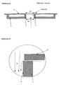
- the Fig. 1 shows a schematic side sectional view of a known from the prior art gas turbine combustor.
- a cover 1 of a combustion chamber head is shown.
- the reference numeral 2 designates a base plate, combustion chamber shingles are designated by the reference numeral 3.
- the combustion chamber shingles 3 have mixing air holes 4 and are fastened to a support structure 6.
- the reference numeral 5 denotes a heat shield with a hole for a burner 8.
- a turbine vane 9 is shown schematically.
- Reference numeral 10 denotes a vane in the compressor outlet.
- a combustion chamber outer housing 11 and a combustion chamber inner housing 12 delimits the combustion chamber.
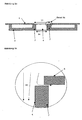
- Fig. 2a and 2b show the configuration of a mixing air hole 4 of the combustion chamber shingle 3 and a corresponding mixing air hole of the support structure 6 according to the prior art. It can be seen that the diameter 13 of the mixing air hole of the support structure 6 is slightly larger than the diameter 14 of the mixing air hole 4 of the combustion chamber shingle 3. Off Fig. 2b it can be seen that the air flow 15 in the mixing air hole 4 additionally draws air from the shingle interior.
- Fig. 3a and 3b show the inventive design in an analogous representation to the Fig. 2a and 2b , It can be seen that the diameter 13 of the mixing air hole of the support structure 6 is significantly or significantly greater than the diameter 14 of the mixing air hole 4 of the combustion chamber shingle 3. From the Fig. 3b It can be seen that a back pressure of Air flow 15 leads to an additional inflow of cooling air into the shingled interior, as soon as a gap between the support structure 6 and the shingle edge 7 is formed.
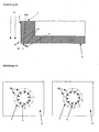
- the Fig. 4a shows an enlarged view of a portion of a combustion chamber shingle 3. It can be seen that 4 additional effusion holes 16 are provided by the shingle edge 7 in the region of the mixing air hole to supply cooling air from the shingled interior for cooling the combustion chamber shingle 3. As can be seen, the effusion holes 16 may be arranged in a different orientation to the plane of the combustion chamber shingle 3.
- the effusion hole 16a is arranged at a very shallow angle, while the effusion holes 16b and 16d extend through the shingle edge 7 and are oriented at a greater angle to the main plane of the combustion chamber shingle 3.
- the effusion hole 16e extends almost perpendicular to the main plane of the combustion chamber shingle 3 and flows through the shingle edge. 7
- the Fig. 4b shows two different embodiments of the effusion holes 16 in the plan view of the mixing air hole 4 of the combustion chamber shingles 3.
- the effusion holes are each arranged radially (regardless of the respective angle of inclination according to FIG Fig. 4a ), while in the right figure the Fig. 4b in addition, a tangential component about the axis of the mixing air hole or a tangential arrangement of the effusion holes 16 is realized. This allows a particularly efficient cooling done.
Landscapes
- Engineering & Computer Science (AREA)
- Chemical & Material Sciences (AREA)
- Combustion & Propulsion (AREA)
- Mechanical Engineering (AREA)
- General Engineering & Computer Science (AREA)
- Turbine Rotor Nozzle Sealing (AREA)
Description
- Die Erfindung bezieht sich auf eine Gasturbinenbrennkammer mit Brennkammerschindeln, wobei die Brennkammerschindeln an einer Tragstruktur der Gasturbinenbrennkammer befestigt sind und jeweils zumindest ein Mischluftloch aufweisen, welches fluchtend zu einem Mischluftloch der Tragstruktur angeordnet ist.
- Aus dem Stand der Technik ist es bekannt, Schindeln in Gasturbinenbrennkammern einzusetzen, um die Trag- und Dichtstruktur vor der intensiven Wärmeeinstrahlung der Flamme zu schützen. Die Tragstruktur bleibt dadurch relativ kühl und behält ihre mechanische Festigkeit. Demgemäß ist es erforderlich, Mischluft durch ein Mischluftloch in der Tragstruktur sowie durch ein Mischluftloch der Brennkammerschindel von außen von einem Ringkanal nach innen in die Brennkammer zu führen.
- Derartige Konstruktionen sind beispielsweise aus der
US 6,145,319 oderEP 972 992 A2 - Die aus dem Stand der Technik bekannten Konstruktionen sind so ausgebildet, dass der Durchmesser des Mischluftloches der Tragstruktur (Schindelträger) höchstens geringfügig größer ist, als der Durchmesser des Mischluftlochs der Brennkammerschindel. Der Größenunterschied dient beim Stand der Technik nur dazu, sicherzustellen, dass bei der ungünstigsten Kombination aller Fertigungs- und Montagetoleranzen der Rand des Mischluftlochs der Brennkammerschindel nicht vom Rand des Mischluftlochs der Tragstruktur überragt wird.
- Falls nun während des Betriebes ein Spalt zwischen dem Schindelrand und der Tragstruktur auftritt, entweicht durch diesen wegen der großen Druckdifferenz zwischen dem Schindelinnenraum und dem Mischluftloch relativ viel Kühlluft.
- Um zu verhindern, dass durch die dabei auftretende Überhitzung die Brennkammerschindel vorzeitig versagt, muss deutlich mehr Kühlluft durch die Brennkammerschindel geleitet werden. Diese zusätzliche Kühlluft steht somit nicht mehr für eine Verbesserung der Brennstoffaufbereitung und der damit verbundenen Stickoxidemissionsverminderung zur Verfügung.
- Die
US-A1-4132066 beschreibt eine Gasturbinenbrennkammer mit Brennkammerschindeln, welche an einer Tragstruktur befestigt sind. Die Tragstruktur sowie die Brennkammerschindel weisen jeweils eine Ausnehmung auf, in welche ein torusförmiges Bauelement eingesetzt ist, welches durch seine ringförmige Struktur die Kühlluft einführt und dabei den Zwischenraum zwischen der Tragstruktur und der Brennkammerschindel vollständig abdichtet bzw. von der in die Brennkammer einströmenden Kühlluft trennt. - Die
GB-A-2353589 - Der Erfindung liegt die Aufgabe zu Grunde, eine Gasturbinenbrennkammer mit Brennkammerschindeln der eingangs genannten Art zu schaffen, welche bei einfachem Aufbau, einfacher, kostengünstiger Herstellbarkeit und einfacher Montage eine hohe Lebensdauer aufweist und Überhitzungen der gesamten Konstruktion vermeidet.
- Erfindungsgemäß wird die Aufgabe durch die Merkmalskombination des Hauptanspruchs gelöst, die Unteransprüche zeigen weitere vorteilhafte Ausgestaltungen der Erfindung.
- Erfindungsgemäß ist vorgesehen, dass der Durchmesser des Mischluftlochs der Tragstruktur deutlich größer ist, als der Durchmesser des Mischluftlochs der Brennkammerschindel.
- Die erfindungsgemäße Ausgestaltung zeichnet sich durch eine Reihe erheblicher Vorteile aus.
- Durch die erfindungsgemäße Wahl der Durchmesserverhältnisse steht der Schindelrand, von der Außenseite der Tragstruktur aus gesehen, deutlich sichtbar in den freien Durchmesser des Mischluftloches vor. Hierdurch bildet sich ein Staudruck auf dem verdickten Schindelrand. Weiterhin wird der Durchflusskoffizient des Mischluftloches erhöht. Tritt nun im Betrieb ein Spalt zwischen dem Schindelrand und dem der Tragstruktur auf, dann wirkt der oben genannte Staudruck einem Ausströmen von Kühlluft aus dem Schindelinnenraum entgegen. Bei entsprechender Wahl des Durchmessers des Mischluftloches der Tragstruktur ist der Staudruck auf dem Schindelrand gleich dem Druck im Schindelinnenraum. Somit wird ein Ausströmen von Kühlluft aus dem Schindelinnenraum gänzlich verhindert.
- Erfindungsgemäß kann bei einer entsprechenden Abstimmung der Durchmesser des Mischluftlochs der Tragstruktur und des Mischluftlochs der Brennkammerschindel erreicht werden, dass durch den starken Staudruck auf dem verdickten Rand der Brennkammerschindel beim Auftreten eines Spalts zwischen der Brennkammerschindel und der Tragstruktur, welcher durch eine Überhitzung der Schindel hervorgerufen wird, zusätzliche Kühlluft aus dem Mischluftloch in den Schindelinnenraum fließt und damit die Kühlung der Brennkammerschindel intensiviert.
- Erfindungsgemäß ist somit eine adaptive Kühlung realisiert, bei welcher die Kühlluftmenge selbsttätig an die Temperaturbelastung der Brennkammerschindel angepasst wird.
- Erfindungsgemäß wird der verdickte Rand der Brennkammerschindel durch ein gesondertes Muster von Effusionslöchern gekühlt. Die Effusionslöcher können dabei auf der Rückseite der Oberfläche der Brennkammerschindel oder im Schindelrand beginnen, wobei sie auf der dem Schindelinnenraum oder der Tragstruktur zugewandten Seite eintreten können. Die Effusionslöcher enden auf der Oberfläche der Brennkammerschindel oder an der Innenseite des Mischluftlochs der Brennkammerschindel. Die Effusionslöcher können ohne oder mit einer Umfangskomponente um die Achse des Mischluftloches zur. Heißgasseite der Brennkammerschindel verlaufen.
- Es ergibt sich somit, dass die Kühlluftmenge im Ausgangszustand der Gasturbinenbrennkammer so gewählt werden kann, dass sie für den normalen Betrieb gerade ausreichend ist. Somit steht die maximale Luftmenge für die Schadgasreduzierung zur Verfügung. In Extremsituationen, bei denen die Brennkammerschindel thermisch stärker belastet wird, wird selbsttätig die Kühlung erhöht, sodass ein langanhaltender und sicherer Betrieb möglich ist.
- Im Folgenden wird die Erfindung anhand eines Ausführungsbeispiels in Verbindung mit der Zeichnung beschrieben. Dabei zeigt:
- Abb. 1
- eine schematische Schnittansicht einer Gasturbinenbrennkammer mit Brennkammerschindeln gemäß dem Stand der Technik,
- Abb. 2a
- eine Schnittansicht durch eine Brennkammerschindel nach dem Stand der Technik,
- Abb. 2b
- eine Detailansicht des Details 2b von
Abb. 2a , - Abb. 3a
- eine Schnittansicht, analog
Abb. 2a einer erfindungsgemäßen Ausgestaltung einer Brennkammerschindel, - Abb. 3b
- eine Detailansicht des Details 3b von
Abb. 3a , - Abb. 4a
- eine Detaildarstellung des Brennkammerschindelrandes analog zu der Darstellung der
Abb. 3a , und - Abb. 4b
- Darstellungen des Randbereichs eines erfindungsgemäßen Mischluftloches in Draufsicht mit unterschiedlicher Anordnung von Effusionslöchern.
- Die
Abb. 1 zeigt eine schematische Seiten-Schnittansicht einer aus dem Stand der Technik bekannten Gasturbinenbrennkammer. Dabei ist eine Abdeckung 1 eines Brennkammerkopfes dargestellt. Das Bezugszeichen 2 bezeichnet eine Grundplatte, Brennkammerschindeln sind mit dem Bezugszeichen 3 bezeichnet. Die Brennkammerschindeln 3 weisen Mischluftlöcher 4 auf und sind an einer Tragstruktur 6 befestigt. Mit dem Bezugszeichen 5 ist ein Hitzeschild mit einem Loch für einen Brenner 8 bezeichnet. Am Auslauf der Brennkammer ist eine Turbinenleitschaufel 9 schematisch dargestellt. Das Bezugszeichen 10 bezeichnet eine Leitschaufel im Verdichterauslass. Ein Brennkammeraußengehäuse 11 und ein Brennkammerinnengehäuse 12 begrenzt die Brennkammer. - Die
Abb. 2a und 2b zeigen die Ausgestaltung eines Mischluftlochs 4 der Brennkammerschindel 3 sowie eines entsprechenden Mischluftloches der Tragstruktur 6 gemäß dem Stand der Technik. Dabei ist ersichtlich, dass der Durchmesser 13 des Mischluftlochs der Tragstruktur 6 geringfügig größer ist, als der Durchmesser 14 des Mischluftlochs 4 der Brennkammerschindel 3. AusAbb. 2b ist ersichtlich, dass die Luftströmung 15 im Mischluftloch 4 zusätzlich Luft aus dem Schindelinnenraum zieht. - Die
Abb. 3a und 3b zeigen die erfindungsgemäße Ausgestaltung in analoger Darstellung zu denAbb. 2a und 2b . Dabei ist ersichtlich, dass der Durchmesser 13 des Mischluftlochs der Tragstruktur 6 deutlicher oder erheblich größer ist, als der Durchmesser 14 des Mischluftlochs 4 der Brennkammerschindel 3. Aus derAbb. 3b ist ersichtlich, dass ein Staudruck der Luftströmung 15 zu einem zusätzlichen Einströmen von Kühlluft in den Schindelinnenraum führt, sobald sich ein Spalt zwischen der Tragstruktur 6 und dem Schindelrand 7 bildet. - Die
Abb. 4a zeigt in vergrößerter Darstellung einen Teilbereich einer erfindungsgemäßen Brennkammerschindel 3. Dabei ist ersichtlich, dass durch den Schindelrand 7 im Bereich des Mischluftlochs 4 zusätzliche Effusionslöcher 16 vorgesehen sind, um Kühlluft aus dem Schindelinnenraum zur Kühlung der Brennkammerschindel 3 zuzuführen. Wie ersichtlich, können die Effusionslöcher 16 in unterschiedlicher Ausrichtung zu der Ebene der Brennkammerschindel 3 angeordnet sein. Das Effusionsloch 16a ist mit einem sehr flachen Winkel angeordnet, während die Effusionslöcher 16b und 16d sich durch den Schindelrand 7 erstrecken und in einem größeren Winkel zur Hauptebene der Brennkammerschindel 3 ausgerichtet sind. Das Effusionsloch 16e erstreckt nahezu senkrecht zur Hauptebene der Brennkammerschindel 3 und durchströmt den Schindelrand 7. - Die
Abb. 4b zeigt zwei unterschiedliche Ausführungsvarianten der Effusionslöcher 16 in der Draufsicht auf das Mischluftloch 4 der Brennkammerschindel 3. In der linken Figur derAbb. 4b sind die Effusionslöcher jeweils radial angeordnet (unabhängig von dem jeweiligen Neigungswinkel gemäßAbb. 4a ), während in der rechten Figur derAbb. 4b zusätzlich eine Tangentialkomponenten um die Achse des Mischluftloches oder eine tangentiale Anordnung der Effusionslöcher 16 realisiert ist. Hierdurch kann eine besonders effiziente Kühlung erfolgen. - Die Erfindung ist nicht auf die gezeigten Ausführungsbeispiele beschränkt, vielmehr ergeben sich im Rahmen der Er-findung vielfältige Abwandlungs- und Modifikationsmöglichkeiten.
-
- 1
- Abdeckung des Brennkammerkopfes
- 2
- Grundplatte
- 3
- Brennkammerschindel
- 4
- Mischluftloch
- 5
- Hitzeschild (mit Loch für Brenner)
- 6
- Tragstruktur
- 7
- Schindelrand
- 8
- Brenner (mit Brennerarm und Drallerzeuger)
- 9
- Turbinenleitschaufel
- 10
- Leitschaufel im Verdichterauslass
- 11
- Brennkammeraußengehäuse
- 12
- Brennkammerinnengehäuse
- 13
- Durchmesser des Mischluftlochs in der Tragstruktur 6
- 14
- Durchmesser des Mischluftlochs 4 in der Schindel 3
- 15
- Luftströmung im Mischluftloch 4
- 16
- Effusionsloch
Claims (7)
- Gasturbinenbrennkammer mit Brennkammerschindeln, wobei die Brennkammerschindeln (3) an einer Tragstruktur (6) der Gasturbinenbrennkammer befestigt sind und jeweils zumindest ein Mischluftloch (4) aufweisen, welches fluchtend zu einem Mischluftloch der Tragstruktur (6) angeordnet ist, wobei der Durchmesser des Mischluftlochs der Tragstruktur (6) um 15 % bis 25 % größer ist, als der Durchmesser (14) des Mischluftlochs (4) der Brennkammerschindel (3), dadurch gekennzeichnet, dass die Brennkammerschindel (3) an ihrem Schindelrand (7) nicht abgedichtet an der Tragstruktur (6) anliegt und am Schindelrand (7) eine Spaltbildung zur Tragstruktur (6) ermöglicht ist, wobei zur Ausbildung eines Staudrucks auf einem Schindelrand (7) der Schindelrand (7), von der Außenseite der Tragstruktur (6) aus gesehen, in den freien Durchmesser des Mischluftlochs (4) vorsteht.
- Gasturbinenbrennkammer nach Anspruch 1, dadurch gekennzeichnet, dass an dem Schindelrand (7) Effusionslöcher (16) zur Verbindung mit dem Schindelinnenraum vorgesehen sind.
- Gasturbinenbrennkammer nach Anspruch 2, dadurch gekennzeichnet, dass die Effusionslöcher (16) im Schindelrand (7) ausgebildet sind.
- Gasturbinenbrennkammer nach Anspruch 2 oder 3, dadurch gekennzeichnet, dass die Effusionslöcher (16) in der Brennkammerschindel (3) ausgebildet sind.
- Gasturbinenbrennkammer nach einem der Ansprüche 2 bis 4, dadurch gekennzeichnet, dass die Effusionslöcher (16) radial zu dem Mischluftloch (4) angeordnet sind.
- Gasturbinenbrennkammer nach einem der Ansprüche 2 bis 4, dadurch gekennzeichnet, dass die Effusionslöcher (16) tangential zu dem Mischluftloch (4) angeordnet sind.
- Gasturbinenbrennkammer nach einem der Ansprüche 2 bis 4, dadurch gekennzeichnet, dass die Effusionslöcher (16) sowohl eine radiale als auch eine tangentiale Komponente zur Achse des Mischluftloches (4) besitzen.
Applications Claiming Priority (2)
| Application Number | Priority Date | Filing Date | Title |
|---|---|---|---|
| DE10214570 | 2002-04-02 | ||
| DE10214570A DE10214570A1 (de) | 2002-04-02 | 2002-04-02 | Mischluftloch in Gasturbinenbrennkammer mit Brennkammerschindeln |
Publications (3)
| Publication Number | Publication Date |
|---|---|
| EP1351022A2 EP1351022A2 (de) | 2003-10-08 |
| EP1351022A3 EP1351022A3 (de) | 2005-01-26 |
| EP1351022B1 true EP1351022B1 (de) | 2010-08-04 |
Family
ID=27816106
Family Applications (1)
| Application Number | Title | Priority Date | Filing Date |
|---|---|---|---|
| EP03001782A Expired - Lifetime EP1351022B1 (de) | 2002-04-02 | 2003-01-28 | Mischluftloch in Gasturbinenbrennkammer mit Brennkammerschindeln |
Country Status (3)
| Country | Link |
|---|---|
| US (1) | US7059133B2 (de) |
| EP (1) | EP1351022B1 (de) |
| DE (2) | DE10214570A1 (de) |
Cited By (1)
| Publication number | Priority date | Publication date | Assignee | Title |
|---|---|---|---|---|
| DE102016222099A1 (de) | 2016-11-10 | 2018-05-17 | Rolls-Royce Deutschland Ltd & Co Kg | Brennkammer einer Gasturbine |
Families Citing this family (50)
| Publication number | Priority date | Publication date | Assignee | Title |
|---|---|---|---|---|
| EP1423645B1 (de) * | 2001-09-07 | 2008-10-08 | Alstom Technology Ltd | Dämpfungsanordnung zur reduzierung von brennkammerpulsationen in einer gasturbinenanlage |
| EP1507116A1 (de) * | 2003-08-13 | 2005-02-16 | Siemens Aktiengesellschaft | Hitzeschildanordnung für eine ein Heissgas führende Komponente, insbesondere für eine Brennkammer einer Gasturbine |
| US7140185B2 (en) * | 2004-07-12 | 2006-11-28 | United Technologies Corporation | Heatshielded article |
| US9587832B2 (en) | 2008-10-01 | 2017-03-07 | United Technologies Corporation | Structures with adaptive cooling |
| US8161752B2 (en) * | 2008-11-20 | 2012-04-24 | Honeywell International Inc. | Combustors with inserts between dual wall liners |
| US9010121B2 (en) | 2010-12-10 | 2015-04-21 | Rolls-Royce Plc | Combustion chamber |
| US9062884B2 (en) | 2011-05-26 | 2015-06-23 | Honeywell International Inc. | Combustors with quench inserts |
| GB201116608D0 (en) * | 2011-09-27 | 2011-11-09 | Rolls Royce Plc | A method of operating a combustion chamber |
| US9038395B2 (en) | 2012-03-29 | 2015-05-26 | Honeywell International Inc. | Combustors with quench inserts |
| US9174309B2 (en) | 2012-07-24 | 2015-11-03 | General Electric Company | Turbine component and a process of fabricating a turbine component |
| DE102012015452A1 (de) * | 2012-08-03 | 2014-04-24 | Rolls-Royce Deutschland Ltd & Co Kg | Gasturbinenbrennkammerwand mit Mischluftöffnungen und Luftleitelementen |
| DE102012022259A1 (de) | 2012-11-13 | 2014-05-28 | Rolls-Royce Deutschland Ltd & Co Kg | Brennkammerschindel einer Gasturbine sowie Verfahren zu deren Herstellung |
| DE102012022199A1 (de) | 2012-11-13 | 2014-05-28 | Rolls-Royce Deutschland Ltd & Co Kg | Brennkammerschindel einer Gasturbine |
| DE102012023297A1 (de) | 2012-11-28 | 2014-06-12 | Rolls-Royce Deutschland Ltd & Co Kg | Schindelbefestigungsanordnung einer Gasturbinenbrennkammer |
| WO2014112992A1 (en) * | 2013-01-16 | 2014-07-24 | United Technologies Corporation | Combustor cooled quench zone array |
| US9228747B2 (en) * | 2013-03-12 | 2016-01-05 | Pratt & Whitney Canada Corp. | Combustor for gas turbine engine |
| WO2014197045A2 (en) | 2013-03-12 | 2014-12-11 | United Technologies Corporation | Active cooling of grommet bosses for a combustor panel of a gas turbine engine |
| WO2014149108A1 (en) | 2013-03-15 | 2014-09-25 | Graves Charles B | Shell and tiled liner arrangement for a combustor |
| EP3039346B1 (de) * | 2013-08-30 | 2022-09-14 | Raytheon Technologies Corporation | Konturierte verdünnungsdurchgänge für eine gasturbinenbrennkammer |
| EP3047128B1 (de) | 2013-09-16 | 2018-10-31 | United Technologies Corporation | Kontrollierte variation des druckabfalls durch effusionskühlung in einer doppelwandigen brennkammer eines gasturbinentriebwerks |
| WO2015039075A1 (en) * | 2013-09-16 | 2015-03-19 | United Technologies Corporation | Angled combustor liner cooling holes through transverse structure within a gas turbine engine combustor |
| DE102013223258A1 (de) | 2013-11-14 | 2015-06-03 | Rolls-Royce Deutschland Ltd & Co Kg | Brennkammerhitzeabschirmelement einer Gasturbine |
| US10502422B2 (en) * | 2013-12-05 | 2019-12-10 | United Technologies Corporation | Cooling a quench aperture body of a combustor wall |
| WO2015084963A1 (en) * | 2013-12-06 | 2015-06-11 | United Technologies Corporation | Cooling a quench aperture body of a combustor wall |
| EP3077640B1 (de) * | 2013-12-06 | 2021-06-02 | Raytheon Technologies Corporation | Brennkammerlöschöffnungskühlung |
| EP3084304B1 (de) * | 2013-12-20 | 2020-08-26 | United Technologies Corporation | Kühlung eines öffnungskörpers einer brennkammerwand |
| DE102014204466A1 (de) | 2014-03-11 | 2015-10-01 | Rolls-Royce Deutschland Ltd & Co Kg | Brennkammer einer Gasturbine |
| DE102014204472A1 (de) | 2014-03-11 | 2015-09-17 | Rolls-Royce Deutschland Ltd & Co Kg | Brennkammerschindel einer Gasturbine |
| DE102014222320A1 (de) | 2014-10-31 | 2016-05-04 | Rolls-Royce Deutschland Ltd & Co Kg | Brennkammerwand einer Gasturbine mit Kühlung für einen Mischluftlochrand |
| US10788212B2 (en) * | 2015-01-12 | 2020-09-29 | General Electric Company | System and method for an oxidant passageway in a gas turbine system with exhaust gas recirculation |
| US10094564B2 (en) | 2015-04-17 | 2018-10-09 | Pratt & Whitney Canada Corp. | Combustor dilution hole cooling system |
| DE102015217161A1 (de) | 2015-09-04 | 2017-03-09 | Rolls-Royce Deutschland Ltd & Co Kg | Baugruppe mit einer Brennkammerschindel für eine Gasturbine |
| EP3139090B1 (de) | 2015-09-04 | 2018-06-13 | Rolls-Royce Deutschland Ltd & Co KG | Baugruppe mit einer brennkammerschindel für eine gasturbine |
| DE102016219424A1 (de) * | 2016-10-06 | 2018-04-12 | Rolls-Royce Deutschland Ltd & Co Kg | Brennkammeranordnung einer Gasturbine sowie Fluggasturbine |
| US10408453B2 (en) | 2017-07-19 | 2019-09-10 | United Technologies Corporation | Dilution holes for gas turbine engines |
| US11268438B2 (en) | 2017-09-15 | 2022-03-08 | General Electric Company | Combustor liner dilution opening |
| US11137140B2 (en) | 2017-10-04 | 2021-10-05 | Raytheon Technologies Corporation | Dilution holes with ridge feature for gas turbine engines |
| US11255543B2 (en) | 2018-08-07 | 2022-02-22 | General Electric Company | Dilution structure for gas turbine engine combustor |
| US11339966B2 (en) | 2018-08-21 | 2022-05-24 | General Electric Company | Flow control wall for heat engine |
| US11029027B2 (en) | 2018-10-03 | 2021-06-08 | Raytheon Technologies Corporation | Dilution/effusion hole pattern for thick combustor panels |
| US11391460B2 (en) | 2019-07-16 | 2022-07-19 | Raytheon Technologies Corporation | Effusion cooling for dilution/quench hole edges in combustor liner panels |
| US11371701B1 (en) | 2021-02-03 | 2022-06-28 | General Electric Company | Combustor for a gas turbine engine |
| US11560837B2 (en) | 2021-04-19 | 2023-01-24 | General Electric Company | Combustor dilution hole |
| US11572835B2 (en) | 2021-05-11 | 2023-02-07 | General Electric Company | Combustor dilution hole |
| US11959643B2 (en) | 2021-06-07 | 2024-04-16 | General Electric Company | Combustor for a gas turbine engine |
| US12085283B2 (en) | 2021-06-07 | 2024-09-10 | General Electric Company | Combustor for a gas turbine engine |
| US12152777B2 (en) | 2021-06-07 | 2024-11-26 | General Electric Company | Combustor for a gas turbine engine |
| US11774098B2 (en) | 2021-06-07 | 2023-10-03 | General Electric Company | Combustor for a gas turbine engine |
| US12146660B2 (en) | 2021-06-07 | 2024-11-19 | General Electric Company | Combustor for a gas turbine engine |
| US11885495B2 (en) | 2021-06-07 | 2024-01-30 | General Electric Company | Combustor for a gas turbine engine including a liner having a looped feature |
Family Cites Families (16)
| Publication number | Priority date | Publication date | Assignee | Title |
|---|---|---|---|---|
| GB1055234A (en) * | 1963-04-30 | 1967-01-18 | Hitachi Ltd | Ultra-high temperature combustion chambers |
| US4132066A (en) * | 1977-09-23 | 1979-01-02 | United Technologies Corporation | Combustor liner for gas turbine engine |
| JPS5857658B2 (ja) * | 1980-04-02 | 1983-12-21 | 工業技術院長 | セラミツクスによる高熱曝露壁面の熱遮断構造 |
| GB2087065B (en) * | 1980-11-08 | 1984-11-07 | Rolls Royce | Wall structure for a combustion chamber |
| US4653279A (en) * | 1985-01-07 | 1987-03-31 | United Technologies Corporation | Integral refilmer lip for floatwall panels |
| GB8703101D0 (en) * | 1987-02-11 | 1987-03-18 | Secr Defence | Gas turbine engine combustion chambers |
| US5687572A (en) * | 1992-11-02 | 1997-11-18 | Alliedsignal Inc. | Thin wall combustor with backside impingement cooling |
| GB9803291D0 (en) * | 1998-02-18 | 1998-04-08 | Chapman H C | Combustion apparatus |
| US6145319A (en) | 1998-07-16 | 2000-11-14 | General Electric Company | Transitional multihole combustion liner |
| EP1022437A1 (de) * | 1999-01-19 | 2000-07-26 | Siemens Aktiengesellschaft | Bauteil zur Verwendung in einer thermischen Machine |
| GB9919981D0 (en) * | 1999-08-24 | 1999-10-27 | Rolls Royce Plc | Combustion apparatus |
| GB9926257D0 (en) * | 1999-11-06 | 2000-01-12 | Rolls Royce Plc | Wall elements for gas turbine engine combustors |
| GB2368902A (en) * | 2000-11-11 | 2002-05-15 | Rolls Royce Plc | A double wall combustor arrangement |
| US6606861B2 (en) | 2001-02-26 | 2003-08-19 | United Technologies Corporation | Low emissions combustor for a gas turbine engine |
| GB2373319B (en) * | 2001-03-12 | 2005-03-30 | Rolls Royce Plc | Combustion apparatus |
| GB2384046B (en) * | 2002-01-15 | 2005-07-06 | Rolls Royce Plc | A double wall combuster tile arrangement |
-
2002
- 2002-04-02 DE DE10214570A patent/DE10214570A1/de not_active Withdrawn
-
2003
- 2003-01-28 EP EP03001782A patent/EP1351022B1/de not_active Expired - Lifetime
- 2003-01-28 DE DE50312938T patent/DE50312938D1/de not_active Expired - Lifetime
- 2003-03-28 US US10/400,553 patent/US7059133B2/en not_active Expired - Fee Related
Cited By (1)
| Publication number | Priority date | Publication date | Assignee | Title |
|---|---|---|---|---|
| DE102016222099A1 (de) | 2016-11-10 | 2018-05-17 | Rolls-Royce Deutschland Ltd & Co Kg | Brennkammer einer Gasturbine |
Also Published As
| Publication number | Publication date |
|---|---|
| DE50312938D1 (de) | 2010-09-16 |
| US20030182942A1 (en) | 2003-10-02 |
| EP1351022A2 (de) | 2003-10-08 |
| US7059133B2 (en) | 2006-06-13 |
| DE10214570A1 (de) | 2004-01-15 |
| EP1351022A3 (de) | 2005-01-26 |
Similar Documents
| Publication | Publication Date | Title |
|---|---|---|
| EP1351022B1 (de) | Mischluftloch in Gasturbinenbrennkammer mit Brennkammerschindeln | |
| EP2738470B1 (de) | Schindelbefestigungsanordnung einer Gasturbinenbrennkammer | |
| DE60110309T2 (de) | Haltevorrichtung einer Verwirbelungsanordnung | |
| DE69936176T2 (de) | Berstschutzring für Turbinen | |
| EP1428983B1 (de) | Abgasturbinengehäuse | |
| DE60212751T2 (de) | Spaltdichtung und Gasturbine mit einer solchen Spaltdichtung | |
| DE102009043883B4 (de) | Mehrfachrohrthermosicherung zum Schutz einer Düse vor einem Flammenhaltungs- oder Flammenrückschlagereignis | |
| EP2809994B1 (de) | Hitzeschildelement für einen verdichterluftbypass um die brennkammer | |
| EP2154431B1 (de) | Thermische Maschine | |
| DE69509794T2 (de) | Halterung für kraftstoffeinspritzdüsen | |
| EP2808611B1 (de) | Injektor zum Einbringen eines Brennstoff-Luft-Gemisches in eine Brennkammer | |
| EP2344723B1 (de) | Gasturbine mit dichtplatten an der turbinenscheibe | |
| EP2191105A1 (de) | Mehrschichtiger abschirmungsring für einen flugantrieb | |
| DE102010038019A1 (de) | Deckbandanordnung mit Sperrelement | |
| EP3219918B1 (de) | Gasturbine mit einer kühleinrichtung zur kühlung von plattformen eines leitschaufelkranzes der gasturbine | |
| DE102014204466A1 (de) | Brennkammer einer Gasturbine | |
| DE10214573A1 (de) | Brennkammer einer Gasturbine mit Starterfilmkühlung | |
| DE102015217161A1 (de) | Baugruppe mit einer Brennkammerschindel für eine Gasturbine | |
| EP2980481A1 (de) | Fluggasturbine mit einer dichtung zur abdichtung einer zündkerze an der brennkammerwand einer gasturbine | |
| DE102010037353A1 (de) | Brennstoffdüsenrollmembrandichtung | |
| DE4324035C2 (de) | Gasturbine | |
| EP2459934B1 (de) | Gasturbinenbrennkammer | |
| EP1724526A1 (de) | Brennkammerschale, Gasturbinenanlage und Verfahren zum An- oder Abfahren einer Gasturbinenanlage | |
| EP2256413A1 (de) | Brenner, Betriebsverfahren und Montageverfahren | |
| DE102021208014B4 (de) | Gasturbinenbrennkammervorrichtung |
Legal Events
| Date | Code | Title | Description |
|---|---|---|---|
| PUAI | Public reference made under article 153(3) epc to a published international application that has entered the european phase |
Free format text: ORIGINAL CODE: 0009012 |
|
| AK | Designated contracting states |
Kind code of ref document: A2 Designated state(s): AT BE BG CH CY CZ DE DK EE ES FI FR GB GR HU IE IT LI LU MC NL PT SE SI SK TR |
|
| AX | Request for extension of the european patent |
Extension state: AL LT LV MK RO |
|
| PUAL | Search report despatched |
Free format text: ORIGINAL CODE: 0009013 |
|
| AK | Designated contracting states |
Kind code of ref document: A3 Designated state(s): AT BE BG CH CY CZ DE DK EE ES FI FR GB GR HU IE IT LI LU MC NL PT SE SI SK TR |
|
| AX | Request for extension of the european patent |
Extension state: AL LT LV MK RO |
|
| 17P | Request for examination filed |
Effective date: 20050314 |
|
| AKX | Designation fees paid |
Designated state(s): DE FR GB |
|
| 17Q | First examination report despatched |
Effective date: 20070620 |
|
| GRAP | Despatch of communication of intention to grant a patent |
Free format text: ORIGINAL CODE: EPIDOSNIGR1 |
|
| GRAS | Grant fee paid |
Free format text: ORIGINAL CODE: EPIDOSNIGR3 |
|
| GRAA | (expected) grant |
Free format text: ORIGINAL CODE: 0009210 |
|
| AK | Designated contracting states |
Kind code of ref document: B1 Designated state(s): DE FR GB |
|
| REG | Reference to a national code |
Ref country code: GB Ref legal event code: FG4D Free format text: NOT ENGLISH |
|
| REF | Corresponds to: |
Ref document number: 50312938 Country of ref document: DE Date of ref document: 20100916 Kind code of ref document: P |
|
| PLBE | No opposition filed within time limit |
Free format text: ORIGINAL CODE: 0009261 |
|
| STAA | Information on the status of an ep patent application or granted ep patent |
Free format text: STATUS: NO OPPOSITION FILED WITHIN TIME LIMIT |
|
| 26N | No opposition filed |
Effective date: 20110506 |
|
| REG | Reference to a national code |
Ref country code: DE Ref legal event code: R097 Ref document number: 50312938 Country of ref document: DE Effective date: 20110506 |
|
| REG | Reference to a national code |
Ref country code: DE Ref legal event code: R082 Ref document number: 50312938 Country of ref document: DE Representative=s name: HOEFER & PARTNER, DE |
|
| REG | Reference to a national code |
Ref country code: DE Ref legal event code: R081 Ref document number: 50312938 Country of ref document: DE Owner name: ROLLS-ROYCE DEUTSCHLAND LTD & CO KG, DE Free format text: FORMER OWNER: ROLLS-ROYCE DEUTSCHLAND LTD & CO KG, 15827 BLANKENFELDE, DE Effective date: 20130402 Ref country code: DE Ref legal event code: R082 Ref document number: 50312938 Country of ref document: DE Representative=s name: HOEFER & PARTNER PATENTANWAELTE MBB, DE Effective date: 20130402 Ref country code: DE Ref legal event code: R082 Ref document number: 50312938 Country of ref document: DE Representative=s name: HOEFER & PARTNER, DE Effective date: 20130402 |
|
| REG | Reference to a national code |
Ref country code: FR Ref legal event code: PLFP Year of fee payment: 14 |
|
| REG | Reference to a national code |
Ref country code: FR Ref legal event code: PLFP Year of fee payment: 15 |
|
| REG | Reference to a national code |
Ref country code: FR Ref legal event code: PLFP Year of fee payment: 16 |
|
| PGFP | Annual fee paid to national office [announced via postgrant information from national office to epo] |
Ref country code: FR Payment date: 20210127 Year of fee payment: 19 |
|
| PGFP | Annual fee paid to national office [announced via postgrant information from national office to epo] |
Ref country code: GB Payment date: 20210128 Year of fee payment: 19 |
|
| PGFP | Annual fee paid to national office [announced via postgrant information from national office to epo] |
Ref country code: DE Payment date: 20210329 Year of fee payment: 19 |
|
| REG | Reference to a national code |
Ref country code: DE Ref legal event code: R119 Ref document number: 50312938 Country of ref document: DE |
|
| GBPC | Gb: european patent ceased through non-payment of renewal fee |
Effective date: 20220128 |
|
| PG25 | Lapsed in a contracting state [announced via postgrant information from national office to epo] |
Ref country code: GB Free format text: LAPSE BECAUSE OF NON-PAYMENT OF DUE FEES Effective date: 20220128 Ref country code: DE Free format text: LAPSE BECAUSE OF NON-PAYMENT OF DUE FEES Effective date: 20220802 |
|
| PG25 | Lapsed in a contracting state [announced via postgrant information from national office to epo] |
Ref country code: FR Free format text: LAPSE BECAUSE OF NON-PAYMENT OF DUE FEES Effective date: 20220131 |