EP1350643A2 - Einsetzvorrichtung für Reifenketten - Google Patents
Einsetzvorrichtung für Reifenketten Download PDFInfo
- Publication number
- EP1350643A2 EP1350643A2 EP03002896A EP03002896A EP1350643A2 EP 1350643 A2 EP1350643 A2 EP 1350643A2 EP 03002896 A EP03002896 A EP 03002896A EP 03002896 A EP03002896 A EP 03002896A EP 1350643 A2 EP1350643 A2 EP 1350643A2
- Authority
- EP
- European Patent Office
- Prior art keywords
- insertion device
- width
- channel
- lateral walls
- rear part
- Prior art date
- Legal status (The legal status is an assumption and is not a legal conclusion. Google has not performed a legal analysis and makes no representation as to the accuracy of the status listed.)
- Granted
Links
Images

Classifications
-
- B—PERFORMING OPERATIONS; TRANSPORTING
- B60—VEHICLES IN GENERAL
- B60C—VEHICLE TYRES; TYRE INFLATION; TYRE CHANGING; CONNECTING VALVES TO INFLATABLE ELASTIC BODIES IN GENERAL; DEVICES OR ARRANGEMENTS RELATED TO TYRES
- B60C27/00—Non-skid devices temporarily attachable to resilient tyres or resiliently-tyred wheels
- B60C27/06—Non-skid devices temporarily attachable to resilient tyres or resiliently-tyred wheels extending over the complete circumference of the tread, e.g. made of chains or cables
-
- B—PERFORMING OPERATIONS; TRANSPORTING
- B60—VEHICLES IN GENERAL
- B60C—VEHICLE TYRES; TYRE INFLATION; TYRE CHANGING; CONNECTING VALVES TO INFLATABLE ELASTIC BODIES IN GENERAL; DEVICES OR ARRANGEMENTS RELATED TO TYRES
- B60C27/00—Non-skid devices temporarily attachable to resilient tyres or resiliently-tyred wheels
- B60C27/003—Mounting aids, e.g. auxiliary tensioning tools, slotted ramps
Definitions
- the present invention relates to an insertion device for snow chains, in particular for insertion of the internal ring of the snow chain in the gap between a pair of twinned wheels of vehicles such as trucks, buses and the like.
- the insertion device according to the invention can also be used for single wheels of any type of vehicle travelling on tyres.
- a snow chain comprises, in general, two lateral elements (flexes, steel wires, cables or the like), which in the condition of use are closed as a ring on the side of the wheel facing inwards and on the side of the wheel facing outwards respectively.
- These lateral elements hereinafter referred to as internal ring and external ring in accordance with their position on the wheel; are connected by a series of chain sections varyingly arranged to create friction on the tread, all this completed by a device for the tautening of said lateral elements, known as a tightener.
- the internal ring For assembly of the snow chains on a tyre, the internal ring has to be made to pass behind the wheel, so as to be closed and tautened by the tightener.
- the operation of passing the internal ring behind the wheel is somewhat awkward and complicated for the user.
- the chain sections connected to the internal ring often end up under the wheel tread, jamming and blocking the forward movement of the internal ring. Consequently the user has to release the chain sections from the tread of the wheel and repeat the operation of passing the internal ring behind the wheel.
- the object of the present invention is to eliminate the disadvantages of the prior art by providing an insertion device for snow chains which is practical, compact, economical and easy to manufacture.
- Another object of the present invention is to provide such an insertion device for snow chains which is versatile and suitable for use for the insertion of various types of snow chains.
- the insertion device for snow chains comprises a base suitable for being rested on the ground and two lateral walls which rise up from the base to form a channel for insertion of the internal ring of a snow chain.
- the internal ring of the snow chain can be made to pass behind the wheel of the vehicle, guided in the channel of the insertion device, without the problem of the chain sections or the hooks of the snow chain blocking under the tread of the vehicle wheel.
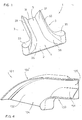
- the insertion device for snow chains is illustrated, according to a first embodiment of the invention.
- the insertion device denoted overall by reference numeral 1, comprises a substantially flat base 2 wherefrom two lateral walls 3 rise up.
- the base 2 has a lower surface suitable for being placed on the ground and has a substantially T-shaped configuration in a plan view. Accordingly, the two lateral walls 3 have a substantially J-shaped configuration. Each lateral wall 3 has a straight rear part 33 and a front curved connection part 30 diverging outwards in relation to the straight rear part.
- Both the internal surface 36 of the curved front part 30 of the lateral wall and the internal surface 31 of the rear part 33 of the lateral wall are substantially rounded or bevelled with decreasing thickness from the base 2 upwards.
- the insertion device 1 therefore behaves as a guide comprising an insertion channel defined on the base 2 between the two lateral walls 3.
- the insertion channel has an entrance 4 having a width substantially greater than the exit 5, so as to act as access for insertion.
- the path of insertion along the insertion channel is linear.
- the insertion device 1 has a front access part defined by the two diverging front portions 30 of the lateral walls having a greater width in relation to the rear part defined by the two rear portions 33 of the lateral walls.
- the width of the rear part of the insertion device is preferably slightly smaller than the width of the gap between two twinned wheels. Instead the rear part of the insertion device has a slight greater width compared to the width of the gap between two twinned wheels.
- the width of the gap between the pair of twinned wheels is approximately 8 cm.
- the rear part of the device has a width slightly smaller than 8 cm and the front part of the device has a width of approximately 18 cm.
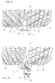
- the insertion device 1 is placed in abutment against the tread 11 of a pair of twinned wheels 10, at the gap 12 between the pair of twinned wheels. Since the rear part of the insertion device 1 has a slightly smaller width compared tot he width of the gap 12 between the pair of wheels, it can be inserted in this gap until the front part of the insertion device in abutment against the tread 11 of the twinned wheels.
- the internal ring 15 of a snow chain is inserted, via the insertion device 1, in the gap 12 defined between the two twinned wheels 10.
- Fig. 4 shows an insertion device 101 according to a second embodiment of the invention.
- the insertion device 101 has a substantially J-shaped base seen in a plan view with a first lateral J-shaped wall 103 and a second substantially curved lateral wall 103' with a greater radius of curvature compared to the wall 103.
- the lateral wall 103 with smaller radius of curvature has a substantially bevelled or rounded internal surface 131.
- the entrance part 104 is always wider than the exit part 105, so as to form access for insertion of the internal ring of the chain. Moreover in this case the insertion channel follows a curved path with an elbow curve.
- Fig. 5 shows an insertion device 201 according to a third embodiment of the invention.
- the insertion device 201 is obtained from two insertion devices 101 according to the second embodiment, so as to define an entrance 204 and two exits 205 placed on the right and on the left in relation to the entrance 204.
- the insertion device 201 defines two insertion channels which follow a curved elbow path, a first insertion channel directed to the left in relation to the entrance 204 and a second insertion channel directed to the right in relation to the entrance 204.
- the device 201 can be used irrespectively for insertion of the snow chains behind the wheels placed on the right side of the vehicle and on the left side of the vehicle.
- the insertion device according to the invention is preferably made in a single part by injection moulding of plastic. However it can also be made in other materials, for example in sheet metal.
Landscapes
- Engineering & Computer Science (AREA)
- Mechanical Engineering (AREA)
- Cleaning Of Streets, Tracks, Or Beaches (AREA)
- Buildings Adapted To Withstand Abnormal External Influences (AREA)
- Heating, Cooling, Or Curing Plastics Or The Like In General (AREA)
- Moulds For Moulding Plastics Or The Like (AREA)
- Chain Conveyers (AREA)
Applications Claiming Priority (2)
| Application Number | Priority Date | Filing Date | Title |
|---|---|---|---|
| IT2002MI000163U ITMI20020163U1 (it) | 2002-03-27 | 2002-03-27 | Dispositivo di inserimento per catene da neve |
| ITMI20020163U | 2002-03-27 |
Publications (3)
| Publication Number | Publication Date |
|---|---|
| EP1350643A2 true EP1350643A2 (de) | 2003-10-08 |
| EP1350643A3 EP1350643A3 (de) | 2003-12-03 |
| EP1350643B1 EP1350643B1 (de) | 2007-11-07 |
Family
ID=11449038
Family Applications (1)
| Application Number | Title | Priority Date | Filing Date |
|---|---|---|---|
| EP03002896A Expired - Lifetime EP1350643B1 (de) | 2002-03-27 | 2003-02-10 | Einsetzvorrichtung für Reifenketten |
Country Status (6)
| Country | Link |
|---|---|
| US (1) | US6863101B2 (de) |
| EP (1) | EP1350643B1 (de) |
| JP (1) | JP4317373B2 (de) |
| AT (1) | ATE377516T1 (de) |
| DE (1) | DE60317251T2 (de) |
| IT (1) | ITMI20020163U1 (de) |
Families Citing this family (5)
| Publication number | Priority date | Publication date | Assignee | Title |
|---|---|---|---|---|
| KR100836811B1 (ko) * | 2007-06-08 | 2008-06-10 | (주) 아펙스테크 | 자동차용 미끄럼 방지구 |
| KR100836812B1 (ko) * | 2007-06-08 | 2008-06-10 | (주) 아펙스테크 | 자동차용 미끄럼 방지구의 연결대 |
| USD618157S1 (en) * | 2009-07-23 | 2010-06-22 | Terry Masters | Chain block |
| US8978519B2 (en) | 2011-10-11 | 2015-03-17 | Hi-Tec Plastics, Inc. | Tire chain installation ramp |
| US11090988B2 (en) | 2019-02-13 | 2021-08-17 | Todd Huffman | Dual tire chain block |
Family Cites Families (11)
| Publication number | Priority date | Publication date | Assignee | Title |
|---|---|---|---|---|
| US2612239A (en) * | 1950-11-10 | 1952-09-30 | Conn Withers | Wheel chock for dual wheel vehicles |
| US3532149A (en) * | 1968-05-24 | 1970-10-06 | Jimmy C Mccord | Vehicle traction device and method of mounting and dismounting |
| US3810530A (en) * | 1973-01-08 | 1974-05-14 | Jarke Corp | Wheel chock |
| US3893500A (en) * | 1974-08-30 | 1975-07-08 | Vernon L Planz | Tire chain caddy |
| US4103870A (en) * | 1977-08-12 | 1978-08-01 | Keisuke Murakami | Instrument for setting a non-skid chain on a car tire |
| US4709432A (en) * | 1984-10-01 | 1987-12-01 | Barrick Fred A | Combination device for applying tire chains and mounting a jack |
| US4693633A (en) * | 1984-11-08 | 1987-09-15 | Louis Giordano | Run-off trough |
| US4828076A (en) * | 1986-11-28 | 1989-05-09 | Norco Industries, Inc. | Lock chock for tandem axle wheels |
| US4956948A (en) * | 1989-10-19 | 1990-09-18 | Richard Hart | Clog resistant gutter-downspout connection unit |
| US5548931A (en) * | 1995-01-03 | 1996-08-27 | Bryant; Johnnie J. | Quick cleaning gutter system |
| US6240680B1 (en) * | 2000-02-22 | 2001-06-05 | Luther Roy Estes | Automatic downspout drain extension |
-
2002
- 2002-03-27 IT IT2002MI000163U patent/ITMI20020163U1/it unknown
-
2003
- 2003-02-10 AT AT03002896T patent/ATE377516T1/de active
- 2003-02-10 EP EP03002896A patent/EP1350643B1/de not_active Expired - Lifetime
- 2003-02-10 DE DE60317251T patent/DE60317251T2/de not_active Expired - Lifetime
- 2003-02-19 US US10/367,896 patent/US6863101B2/en not_active Expired - Fee Related
- 2003-03-17 JP JP2003071385A patent/JP4317373B2/ja not_active Expired - Fee Related
Also Published As
| Publication number | Publication date |
|---|---|
| ITMI20020163U1 (it) | 2003-09-29 |
| ITMI20020163V0 (it) | 2002-03-27 |
| ATE377516T1 (de) | 2007-11-15 |
| US6863101B2 (en) | 2005-03-08 |
| DE60317251D1 (de) | 2007-12-20 |
| DE60317251T2 (de) | 2008-08-28 |
| EP1350643A3 (de) | 2003-12-03 |
| JP2003291617A (ja) | 2003-10-15 |
| US20030188816A1 (en) | 2003-10-09 |
| JP4317373B2 (ja) | 2009-08-19 |
| EP1350643B1 (de) | 2007-11-07 |
Similar Documents
| Publication | Publication Date | Title |
|---|---|---|
| US6244781B1 (en) | Apparatus for protecting structural supports | |
| US5454413A (en) | Automobile traction enhancement device | |
| EP1350643A2 (de) | Einsetzvorrichtung für Reifenketten | |
| CA2322091A1 (en) | Traction device for a wheeled vehicle | |
| BR0116584B1 (pt) | pneu para rodas de veìculo, par de pneus para veìculos de duas rodas, veìculo a motor equipado com um par de pneus e métodos para emborrachar cordonéis de reforço metálicos para pneus para rodas de veìculos e para assentar pelo menos um cordonel de reforço metálico sobre o tambor de confecção de um pneu para rodas de veìculos. | |
| EP1099572A3 (de) | Schallabsorbierender Einbau aus flexiblen Fasern für einen Fahrzeugluftreifen | |
| DE69515948D1 (de) | Luftreifen mit einem Gürtel: Stahl-Aramide | |
| ATE258854T1 (de) | Fahrzeugreifen | |
| US4749015A (en) | Non-skid device for tires | |
| EP0465999B1 (de) | Reifen mit geneigten, elastischen Stützblöcken an seiner äusseren Oberfläche | |
| US5776271A (en) | Tire anti-skid apparatus | |
| US7966800B2 (en) | Reduced noise drag chain system | |
| EP1752320A1 (de) | Schneekette mit elastischem Montiersystem | |
| US7165658B1 (en) | Emergency banking device | |
| JP2002506764A (ja) | 滑り止め装置 | |
| EP1479535A3 (de) | Zweiteiliger Reifen mit einem verbesserten Verstärkungsgürtel | |
| SI1547818T1 (sl) | Avtoplašč z izboljšano vzdržljivostjo krone | |
| JPH02234816A (ja) | タイヤ滑り止め装置 | |
| WO1999065713A1 (en) | Anti-skid tire chain with zigzag pattern cross chain element of variable lengths | |
| JP4333977B2 (ja) | タイヤ滑り止め装置 | |
| KR200225955Y1 (ko) | 자동차 타이어용 미끄럼 방지구 | |
| JP6227832B1 (ja) | 滑り止め装置及び滑り止めシステム | |
| JPH07205622A (ja) | タイヤチェーン | |
| EP1172485A2 (de) | Eine Anlage zum Schützen von Stützgerüsten | |
| ITVI20060263A1 (it) | Mezzi antiscivolo ad elevata sicurezza applicabili su ruote di autoveicoli in caso di neve e ghiaccio |
Legal Events
| Date | Code | Title | Description |
|---|---|---|---|
| PUAI | Public reference made under article 153(3) epc to a published international application that has entered the european phase |
Free format text: ORIGINAL CODE: 0009012 |
|
| AK | Designated contracting states |
Kind code of ref document: A2 Designated state(s): AT BE BG CH CY CZ DE DK EE ES FI FR GB GR HU IE IT LI LU MC NL PT SE SI SK TR |
|
| AX | Request for extension of the european patent |
Extension state: AL LT LV MK RO |
|
| PUAL | Search report despatched |
Free format text: ORIGINAL CODE: 0009013 |
|
| AK | Designated contracting states |
Kind code of ref document: A3 Designated state(s): AT BE BG CH CY CZ DE DK EE ES FI FR GB GR HU IE IT LI LU MC NL PT SE SI SK TR |
|
| AX | Request for extension of the european patent |
Extension state: AL LT LV MK RO |
|
| 17P | Request for examination filed |
Effective date: 20040521 |
|
| AKX | Designation fees paid |
Designated state(s): AT BE BG CH CY CZ DE DK EE ES FI FR GB GR HU IE IT LI LU MC NL PT SE SI SK TR |
|
| RAP1 | Party data changed (applicant data changed or rights of an application transferred) |
Owner name: THULE S.P.A. |
|
| 17Q | First examination report despatched |
Effective date: 20061221 |
|
| GRAP | Despatch of communication of intention to grant a patent |
Free format text: ORIGINAL CODE: EPIDOSNIGR1 |
|
| GRAS | Grant fee paid |
Free format text: ORIGINAL CODE: EPIDOSNIGR3 |
|
| GRAA | (expected) grant |
Free format text: ORIGINAL CODE: 0009210 |
|
| AK | Designated contracting states |
Kind code of ref document: B1 Designated state(s): AT BE BG CH CY CZ DE DK EE ES FI FR GB GR HU IE IT LI LU MC NL PT SE SI SK TR |
|
| REG | Reference to a national code |
Ref country code: GB Ref legal event code: FG4D |
|
| REG | Reference to a national code |
Ref country code: IE Ref legal event code: FG4D |
|
| REG | Reference to a national code |
Ref country code: CH Ref legal event code: EP |
|
| REF | Corresponds to: |
Ref document number: 60317251 Country of ref document: DE Date of ref document: 20071220 Kind code of ref document: P |
|
| PG25 | Lapsed in a contracting state [announced via postgrant information from national office to epo] |
Ref country code: LI Free format text: LAPSE BECAUSE OF FAILURE TO SUBMIT A TRANSLATION OF THE DESCRIPTION OR TO PAY THE FEE WITHIN THE PRESCRIBED TIME-LIMIT Effective date: 20071107 Ref country code: SE Free format text: LAPSE BECAUSE OF FAILURE TO SUBMIT A TRANSLATION OF THE DESCRIPTION OR TO PAY THE FEE WITHIN THE PRESCRIBED TIME-LIMIT Effective date: 20080207 Ref country code: ES Free format text: LAPSE BECAUSE OF FAILURE TO SUBMIT A TRANSLATION OF THE DESCRIPTION OR TO PAY THE FEE WITHIN THE PRESCRIBED TIME-LIMIT Effective date: 20080218 Ref country code: NL Free format text: LAPSE BECAUSE OF FAILURE TO SUBMIT A TRANSLATION OF THE DESCRIPTION OR TO PAY THE FEE WITHIN THE PRESCRIBED TIME-LIMIT Effective date: 20071107 Ref country code: CH Free format text: LAPSE BECAUSE OF FAILURE TO SUBMIT A TRANSLATION OF THE DESCRIPTION OR TO PAY THE FEE WITHIN THE PRESCRIBED TIME-LIMIT Effective date: 20071107 |
|
| NLV1 | Nl: lapsed or annulled due to failure to fulfill the requirements of art. 29p and 29m of the patents act | ||
| PG25 | Lapsed in a contracting state [announced via postgrant information from national office to epo] |
Ref country code: BG Free format text: LAPSE BECAUSE OF FAILURE TO SUBMIT A TRANSLATION OF THE DESCRIPTION OR TO PAY THE FEE WITHIN THE PRESCRIBED TIME-LIMIT Effective date: 20080207 Ref country code: SI Free format text: LAPSE BECAUSE OF FAILURE TO SUBMIT A TRANSLATION OF THE DESCRIPTION OR TO PAY THE FEE WITHIN THE PRESCRIBED TIME-LIMIT Effective date: 20071107 |
|
| REG | Reference to a national code |
Ref country code: CH Ref legal event code: PL |
|
| ET | Fr: translation filed | ||
| PG25 | Lapsed in a contracting state [announced via postgrant information from national office to epo] |
Ref country code: DK Free format text: LAPSE BECAUSE OF FAILURE TO SUBMIT A TRANSLATION OF THE DESCRIPTION OR TO PAY THE FEE WITHIN THE PRESCRIBED TIME-LIMIT Effective date: 20071107 Ref country code: CZ Free format text: LAPSE BECAUSE OF FAILURE TO SUBMIT A TRANSLATION OF THE DESCRIPTION OR TO PAY THE FEE WITHIN THE PRESCRIBED TIME-LIMIT Effective date: 20071107 |
|
| PG25 | Lapsed in a contracting state [announced via postgrant information from national office to epo] |
Ref country code: BE Free format text: LAPSE BECAUSE OF FAILURE TO SUBMIT A TRANSLATION OF THE DESCRIPTION OR TO PAY THE FEE WITHIN THE PRESCRIBED TIME-LIMIT Effective date: 20071107 Ref country code: SK Free format text: LAPSE BECAUSE OF FAILURE TO SUBMIT A TRANSLATION OF THE DESCRIPTION OR TO PAY THE FEE WITHIN THE PRESCRIBED TIME-LIMIT Effective date: 20071107 |
|
| PLBE | No opposition filed within time limit |
Free format text: ORIGINAL CODE: 0009261 |
|
| STAA | Information on the status of an ep patent application or granted ep patent |
Free format text: STATUS: NO OPPOSITION FILED WITHIN TIME LIMIT |
|
| PG25 | Lapsed in a contracting state [announced via postgrant information from national office to epo] |
Ref country code: PT Free format text: LAPSE BECAUSE OF FAILURE TO SUBMIT A TRANSLATION OF THE DESCRIPTION OR TO PAY THE FEE WITHIN THE PRESCRIBED TIME-LIMIT Effective date: 20080407 |
|
| 26N | No opposition filed |
Effective date: 20080808 |
|
| GBPC | Gb: european patent ceased through non-payment of renewal fee |
Effective date: 20080210 |
|
| PG25 | Lapsed in a contracting state [announced via postgrant information from national office to epo] |
Ref country code: MC Free format text: LAPSE BECAUSE OF NON-PAYMENT OF DUE FEES Effective date: 20080228 |
|
| PG25 | Lapsed in a contracting state [announced via postgrant information from national office to epo] |
Ref country code: IE Free format text: LAPSE BECAUSE OF NON-PAYMENT OF DUE FEES Effective date: 20080211 Ref country code: GR Free format text: LAPSE BECAUSE OF FAILURE TO SUBMIT A TRANSLATION OF THE DESCRIPTION OR TO PAY THE FEE WITHIN THE PRESCRIBED TIME-LIMIT Effective date: 20080208 Ref country code: EE Free format text: LAPSE BECAUSE OF FAILURE TO SUBMIT A TRANSLATION OF THE DESCRIPTION OR TO PAY THE FEE WITHIN THE PRESCRIBED TIME-LIMIT Effective date: 20071107 |
|
| PG25 | Lapsed in a contracting state [announced via postgrant information from national office to epo] |
Ref country code: FI Free format text: LAPSE BECAUSE OF FAILURE TO SUBMIT A TRANSLATION OF THE DESCRIPTION OR TO PAY THE FEE WITHIN THE PRESCRIBED TIME-LIMIT Effective date: 20071107 |
|
| PG25 | Lapsed in a contracting state [announced via postgrant information from national office to epo] |
Ref country code: GB Free format text: LAPSE BECAUSE OF NON-PAYMENT OF DUE FEES Effective date: 20080210 |
|
| PG25 | Lapsed in a contracting state [announced via postgrant information from national office to epo] |
Ref country code: CY Free format text: LAPSE BECAUSE OF FAILURE TO SUBMIT A TRANSLATION OF THE DESCRIPTION OR TO PAY THE FEE WITHIN THE PRESCRIBED TIME-LIMIT Effective date: 20071107 |
|
| PG25 | Lapsed in a contracting state [announced via postgrant information from national office to epo] |
Ref country code: IT Free format text: LAPSE BECAUSE OF NON-PAYMENT OF DUE FEES Effective date: 20080210 |
|
| PG25 | Lapsed in a contracting state [announced via postgrant information from national office to epo] |
Ref country code: LU Free format text: LAPSE BECAUSE OF NON-PAYMENT OF DUE FEES Effective date: 20080210 Ref country code: HU Free format text: LAPSE BECAUSE OF FAILURE TO SUBMIT A TRANSLATION OF THE DESCRIPTION OR TO PAY THE FEE WITHIN THE PRESCRIBED TIME-LIMIT Effective date: 20080508 |
|
| PG25 | Lapsed in a contracting state [announced via postgrant information from national office to epo] |
Ref country code: TR Free format text: LAPSE BECAUSE OF FAILURE TO SUBMIT A TRANSLATION OF THE DESCRIPTION OR TO PAY THE FEE WITHIN THE PRESCRIBED TIME-LIMIT Effective date: 20071107 |
|
| PGFP | Annual fee paid to national office [announced via postgrant information from national office to epo] |
Ref country code: AT Payment date: 20110214 Year of fee payment: 9 |
|
| REG | Reference to a national code |
Ref country code: AT Ref legal event code: MM01 Ref document number: 377516 Country of ref document: AT Kind code of ref document: T Effective date: 20120210 |
|
| PG25 | Lapsed in a contracting state [announced via postgrant information from national office to epo] |
Ref country code: AT Free format text: LAPSE BECAUSE OF NON-PAYMENT OF DUE FEES Effective date: 20120210 |
|
| PGFP | Annual fee paid to national office [announced via postgrant information from national office to epo] |
Ref country code: FR Payment date: 20140211 Year of fee payment: 12 Ref country code: IT Payment date: 20140109 Year of fee payment: 12 |
|
| PGFP | Annual fee paid to national office [announced via postgrant information from national office to epo] |
Ref country code: DE Payment date: 20140417 Year of fee payment: 12 |
|
| REG | Reference to a national code |
Ref country code: DE Ref legal event code: R119 Ref document number: 60317251 Country of ref document: DE |
|
| REG | Reference to a national code |
Ref country code: FR Ref legal event code: ST Effective date: 20151030 |
|
| PG25 | Lapsed in a contracting state [announced via postgrant information from national office to epo] |
Ref country code: IT Free format text: LAPSE BECAUSE OF NON-PAYMENT OF DUE FEES Effective date: 20150210 |
|
| PG25 | Lapsed in a contracting state [announced via postgrant information from national office to epo] |
Ref country code: DE Free format text: LAPSE BECAUSE OF NON-PAYMENT OF DUE FEES Effective date: 20150901 |
|
| PG25 | Lapsed in a contracting state [announced via postgrant information from national office to epo] |
Ref country code: FR Free format text: LAPSE BECAUSE OF NON-PAYMENT OF DUE FEES Effective date: 20150302 |