EP1350640A1 - Pneumatique doté d'une antenne réceptrice - Google Patents
Pneumatique doté d'une antenne réceptrice Download PDFInfo
- Publication number
- EP1350640A1 EP1350640A1 EP03006543A EP03006543A EP1350640A1 EP 1350640 A1 EP1350640 A1 EP 1350640A1 EP 03006543 A EP03006543 A EP 03006543A EP 03006543 A EP03006543 A EP 03006543A EP 1350640 A1 EP1350640 A1 EP 1350640A1
- Authority
- EP
- European Patent Office
- Prior art keywords
- tire
- receiving antenna
- tire according
- complex
- antenna
- Prior art date
- Legal status (The legal status is an assumption and is not a legal conclusion. Google has not performed a legal analysis and makes no representation as to the accuracy of the status listed.)
- Granted
Links
Images


Classifications
-
- G—PHYSICS
- G06—COMPUTING; CALCULATING OR COUNTING
- G06K—GRAPHICAL DATA READING; PRESENTATION OF DATA; RECORD CARRIERS; HANDLING RECORD CARRIERS
- G06K19/00—Record carriers for use with machines and with at least a part designed to carry digital markings
- G06K19/04—Record carriers for use with machines and with at least a part designed to carry digital markings characterised by the shape
-
- B—PERFORMING OPERATIONS; TRANSPORTING
- B60—VEHICLES IN GENERAL
- B60C—VEHICLE TYRES; TYRE INFLATION; TYRE CHANGING; CONNECTING VALVES TO INFLATABLE ELASTIC BODIES IN GENERAL; DEVICES OR ARRANGEMENTS RELATED TO TYRES
- B60C23/00—Devices for measuring, signalling, controlling, or distributing tyre pressure or temperature, specially adapted for mounting on vehicles; Arrangement of tyre inflating devices on vehicles, e.g. of pumps or of tanks; Tyre cooling arrangements
- B60C23/02—Signalling devices actuated by tyre pressure
- B60C23/04—Signalling devices actuated by tyre pressure mounted on the wheel or tyre
- B60C23/0408—Signalling devices actuated by tyre pressure mounted on the wheel or tyre transmitting the signals by non-mechanical means from the wheel or tyre to a vehicle body mounted receiver
- B60C23/0422—Signalling devices actuated by tyre pressure mounted on the wheel or tyre transmitting the signals by non-mechanical means from the wheel or tyre to a vehicle body mounted receiver characterised by the type of signal transmission means
- B60C23/0433—Radio signals
-
- B—PERFORMING OPERATIONS; TRANSPORTING
- B60—VEHICLES IN GENERAL
- B60C—VEHICLE TYRES; TYRE INFLATION; TYRE CHANGING; CONNECTING VALVES TO INFLATABLE ELASTIC BODIES IN GENERAL; DEVICES OR ARRANGEMENTS RELATED TO TYRES
- B60C23/00—Devices for measuring, signalling, controlling, or distributing tyre pressure or temperature, specially adapted for mounting on vehicles; Arrangement of tyre inflating devices on vehicles, e.g. of pumps or of tanks; Tyre cooling arrangements
- B60C23/02—Signalling devices actuated by tyre pressure
- B60C23/04—Signalling devices actuated by tyre pressure mounted on the wheel or tyre
- B60C23/0491—Constructional details of means for attaching the control device
- B60C23/0493—Constructional details of means for attaching the control device for attachment on the tyre
-
- G—PHYSICS
- G06—COMPUTING; CALCULATING OR COUNTING
- G06K—GRAPHICAL DATA READING; PRESENTATION OF DATA; RECORD CARRIERS; HANDLING RECORD CARRIERS
- G06K19/00—Record carriers for use with machines and with at least a part designed to carry digital markings
- G06K19/06—Record carriers for use with machines and with at least a part designed to carry digital markings characterised by the kind of the digital marking, e.g. shape, nature, code
- G06K19/067—Record carriers with conductive marks, printed circuits or semiconductor circuit elements, e.g. credit or identity cards also with resonating or responding marks without active components
- G06K19/07—Record carriers with conductive marks, printed circuits or semiconductor circuit elements, e.g. credit or identity cards also with resonating or responding marks without active components with integrated circuit chips
- G06K19/077—Constructional details, e.g. mounting of circuits in the carrier
- G06K19/07749—Constructional details, e.g. mounting of circuits in the carrier the record carrier being capable of non-contact communication, e.g. constructional details of the antenna of a non-contact smart card
- G06K19/07758—Constructional details, e.g. mounting of circuits in the carrier the record carrier being capable of non-contact communication, e.g. constructional details of the antenna of a non-contact smart card arrangements for adhering the record carrier to further objects or living beings, functioning as an identification tag
- G06K19/07764—Constructional details, e.g. mounting of circuits in the carrier the record carrier being capable of non-contact communication, e.g. constructional details of the antenna of a non-contact smart card arrangements for adhering the record carrier to further objects or living beings, functioning as an identification tag the adhering arrangement making the record carrier attachable to a tire
-
- H—ELECTRICITY
- H01—ELECTRIC ELEMENTS
- H01Q—ANTENNAS, i.e. RADIO AERIALS
- H01Q1/00—Details of, or arrangements associated with, antennas
- H01Q1/12—Supports; Mounting means
- H01Q1/22—Supports; Mounting means by structural association with other equipment or articles
- H01Q1/2208—Supports; Mounting means by structural association with other equipment or articles associated with components used in interrogation type services, i.e. in systems for information exchange between an interrogator/reader and a tag/transponder, e.g. in Radio Frequency Identification [RFID] systems
- H01Q1/2241—Supports; Mounting means by structural association with other equipment or articles associated with components used in interrogation type services, i.e. in systems for information exchange between an interrogator/reader and a tag/transponder, e.g. in Radio Frequency Identification [RFID] systems used in or for vehicle tyres
Definitions
- the present invention relates to a tire provided with at least one receiving antenna of a receiving device including at least one object remotely controlled from a emitting device external to the tire.
- the receiving device and the emitting device communicate without contact via the receiving antenna, which is particularly interesting since they are animated by a movement relative to each other.
- the emissive device is intended to transmit energy and / or information to the object which can be a sensor, a counter or a device performing a other function.
- the sensor can in particular be a force sensor, a temperature sensor, a pressure sensor.
- the object is intended, where appropriate, to communicate data by example of signals relating to measurements, counting or other, to the emitting device.
- the object is therefore connected to at least one first inductive antenna called a receiver which must be coupled electromagnetically with at least a second so-called inductive antenna emissive of the emissive device.
- This emitting device will supply the object with energy and / or control its operation and if necessary recover the data it provides.
- the two antennas are formed of a loop conductor arranged in one or more turns. The two antennas will communicate around a working frequency v. The principle is to generate from the emitting device an electromagnetic field at the working frequency ⁇ via from which energy and / or information will be transmitted.
- Energy is transmitted by the carrier, it is a function of the amplitude of this last.
- the emissive device comprises, in addition to the emissive antenna, means electronics to generate the working frequency ⁇ and a modulation stage in order to be able transmit information in electromagnetic form around the working frequency towards the object.
- the information is transmitted by the modulation of this same carrier, it can be of amplitude, frequency, phase.
- the emissive device may also include means for processing the data received from the object.
- the receiving device itself comprises, cooperating with the object, a circuit electronic, this circuit can be a rectifier circuit.
- Patent application FR-A1-2,771,965 describes a tire with a receiving antenna connected to a sensor.
- the antenna and the sensor are installed in the pneumatic.
- the antenna is intended to couple electromagnetically with another antenna located outside the tire.
- the rectangular receiving antenna when it is laid flat, extends along the periphery of the tire under its tread between a sealing layer (also known as an inner rubber), located on the side of the internal face of the pneumatic, and the radial carcass reinforcement.
- the working frequency ⁇ is an important parameter because it conditions the characteristics of the receiving antenna of the receiving device and those of the transmitting antenna of the emitting device.
- the receiving antenna has a self resonant frequency which is function of its intrinsic characteristics, i.e. the resistance of its conductor, the length of its conductor, the value of the intrinsic capacity distributed along its conductor, its surface and external characteristics linked to its environment such as the size of parasitic capacities, the propensity of the medium to channel the magnetic field lines.
- the receiving antenna of the device receiver must be tuned on the working frequency v.
- the tuning is usually done using a tuning capacitor mounted in parallel with the antenna. In agreement, the following relation is checked:
- LC (2 ⁇ ) 2 1 with L inductance of the receiving antenna, C overall capacity of the receiving antenna
- L and C are the quantities equivalent to the working frequency seen by the reception device.
- C will be the sum of all the capacities brought into play at the level of the receiving antenna: intrinsic capacity of the antenna, parasitic capacity and capacity of the tuning capacitor.
- a long and narrow antenna shape also leads to a reduction in the self resonant frequency.
- the receiving antenna described in patent FR-A1-2,771,965 risks, because of its location, not to couple properly to the emissive antenna outside the pneumatic. Indeed, compared to the outside of the tire, it is located under the reinforcement carcass which is electrically conductive and which will then act as a Faraday cage.
- the present invention aims to overcome the drawbacks mentioned above, and in particular aims to improve the agreement between a receiving antenna which is fitted with a tire and an emissive antenna located outside the tire, for example on a vehicle equipped of the tire, without having to reduce the area of the receiving antenna connected to the object or to lower the frequency of work.
- the present invention provides a tire equipped with least one receiving antenna of a receiving device which includes an object intended to be remotely controlled by electromagnetic coupling with at least one emissive antenna.
- This antenna receiver is intended to be connected to the object and is divided into several parts in a loop arranged in a parallel arrangement, these looped parts each having a surface, these surfaces being globally juxtaposed so that the looped parts are coupled successively and continuously on the transmitting antenna.
- tire does not only the tire inflated to a certain nominal pressure for its operation normal, but also a non-pneumatic elastic bandage.
- pneumatic is meant so generally any product equipped with a tread which rolls on the roadway.
- the receiving antenna has a useful reception area with the antenna emissive and the sum of the surfaces of all the looped parts is substantially equal to the useful surface of the receiving antenna.
- the surface of the receiving antenna can advantageously be much larger than that of the emitting antenna.
- the loop parts being formed of a conductor, a conductor portion of a first loop part and a conductor portion of a second loop part, close to the first part in a loop, are separated by as little space as possible.
- the looped parts are separated, on the side of the object, by as little space as possible.
- a tuning capacitor can be mounted in parallel with at least one of the looped parts.
- the antenna is advantageously shielded to reduce its electrical radiation, in particular to near the object and / or the electronic circuit.
- the receiving antenna can be immobilized between two sheets of a material electrically insulating to form a complex which is implanted in the tire.
- the tire may include, in a crown area, at least one crown reinforcement surrounded by a tread, the complex being inserted between the crown reinforcement and tread.
- the sheets of the complex in a material having mechanical properties close to those of the tread so that the insertion of the receiving antenna minimally disturbs the behavior of the tire.
- the tire comprising a reinforcement of carcass covered towards the outside with an external flank
- the complex can be inserted between the carcass reinforcement and the outer side.
- the sheets of the complex can be produced in an elastomer loaded with silica and carbon black, this material being lightly loaded with carbon black so as to leave electrically insulating.
- This driver can include a or more sons.
- the conductor can be made with one or more wires which are the same nature as the reinforcing wires conventionally used in the tire. he can steel surface brass-plated steel wire, or any other wire or cable treated or coated suitable for sticking directly to rubber.
- the conductor is wavy with a suitable wavy pitch deformations existing at the location chosen for the installation of the antenna, so as not to disturb the mechanics of the tire during driving.
- the conductor can be glued to at least one of the sheets of the complex to guarantee good performance over time of the complex.
- the tire can be equipped with the object.
- the latter can cooperate with a electronic circuit with which the tire is also fitted.
- the electronic circuit may include a single rectifier circuit, the parts loop having at least one end connected to the input of the rectifier circuit, the object being connected at the output of the rectifier circuit.
- the electronic circuit may include several circuits rectifiers, each looped part having at least one end connected to the input of one of the rectifier circuits, rectifier circuits having their outputs connected in series with the object.
- the object and / or the electronic circuit can / can be located in a zone tire crown.
- the object and / or the electronic circuit can / can be located in a sidewall of the tire.
- the object and / or the electronic circuit can / can be located in an internal volume delimited by the tire.
- the object and / or the electronic circuit can / can be located in the complex.
- the object can be a sensor, a counter or even an electronic label.
- the object and / or the electronic circuit can advantageously be shielded by electric field.
- the loaded elastomer forms a tire tread or else contributes to forming a sidewall of the tire depending on whether the antenna is in the sidewall or in the top.
- the method may include a step of installing at least one reinforcement of top on the carcass before the installation of the complex.
- It can also include a drilling step in the carcass of a hole opening into an internal volume delimited by the tire, this hole being intended to contain connection conductors for the connection between the receiving antenna and the object, the object found in the internal volume. This step is followed by a filling step before cooking, from inside the tire, the drilled hole containing the conductors.
- the stage of preparation of the complex can include carrying out at least one extension in which connection conductors are immobilized for the connection between the receiving antenna and the object, this extension being folded down onto a sidewall of the tire when the complex is placed on a crown area of the tire or on the crown area when the complex is placed on its side.
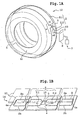
- FIG. 1A There is a schematic form of a tire 12 equipped with a receiving device 1 comprising at least one object 10, for example a force sensor, intended to be remote controlled from an emitting device 7 outside the tire 12.
- a receiving device 1 comprising at least one object 10, for example a force sensor, intended to be remote controlled from an emitting device 7 outside the tire 12.
- Telecontrol means either a power supply at a distance from the object, either a remote communication between the object and the emitting device, or the two functions.
- the object 10 is connected to at least one inductive receiving antenna 2 intended to be electromagnetically couple to at least one other inductive emissive antenna 8 of the emissive device 7.
- the object 10 could include a sensor other than a force sensor, it could be a temperature sensor, a pressure sensor, etc. It is possible that the object comprises instead of a sensor a counter, an electronic label to identify the pneumatic, a control device for example or a combination of several elements previously cited.
- the receiving antenna 2 connected to the object 10 is located at the top of the tire 12 under the tread 16 as illustrated in the section of FIG. 1C.
- the receiving antenna 2 is movable at the rate of the tire.
- the receiving antenna 2 is formed of several parts in loop 2.1, 2.2.
- the different loop parts 2.1, 2.2 are arranged in a parallel arrangement.
- the looped parts comprise a conductor 9 arranged in a single turn, it is understood that they could have several.
- Each of the looping parts 2.1, 2.2 has a surface which corresponds to the surface of a turn and these surfaces referenced s1, s2 are generally juxtaposed. That means that roughly speaking they are side by side and not opposite.
- the loop parts 2.1, 2.2 then couple successively and continuously to the emitting antenna 8.
- the receiving antenna 2 has a useful reception area s with the antenna emissive 8 of the emissive device 7 substantially equal to the sum of the areas s1, s2 of the different loop parts 2.1, 2.2.
- useful area is meant the maximum area which serves actually for transmission and for which online losses are acceptable.
- FIG. 9A When the receiving antenna is not fragmented as in the prior art, its surface is not totally useful.
- FIG. 9A, 9B There is a conventional receiving antenna 20 for tires and an emitting antenna 80 rectangular.
- the large receiving antenna 20 is substantially rectangular, when unwound flat. These antennas must couple with each other during the tire rotation.
- the receiving antenna 20 is connected to an object 10.
- the two antennas 20, 80 are coupled, an electric current flows in the receiving antenna 20.
- the transmitting antenna 80 is far from the connection between the receiving antenna 20 and the object 10 (FIG. 9A), because of the inevitable line losses due in particular to stray capacitances, practically no signal arrives at the object, the coupling is not satisfactory.
- the transmitting antenna 80 when the transmitting antenna 80 is near the connection between the receiving antenna 20 and object 10 (FIG. 9B), the signal arrives correctly at object 10 practically without losses.
- the receiving antenna 20 has an unnecessary area which is materialized by hatching, its surface useful is smaller than its actual area. In the invention, by breaking up the receiving antenna, we remove this unnecessary area.
- the emitting device 7 is outside the tire 12, it is located for example on the vehicle on which the tire 12 is mounted.
- the emitting device 7 can include the vehicle battery for power supply and be provided with an emissive antenna 8.
- the emissive antenna 8 can be located in the wing of the vehicle for be opposite the receiving antenna 2.
- FIG. 1B partially shows the receiving antenna 2, of a tire according to the invention, unwound flat. It has two loop parts 2.1, 2.2. Each of these loop parts 2.1, 2.2 has two large portions 2a, 2b substantially parallel, they follow the periphery of the crown of the tire 12. These large portions 2a, 2b are arranged so that their relative spacing disturbs the mechanics as little as possible rolling of the tire once it is finalized and vulcanized.
- the two large portions 2a, 2b of the same loop part are joined, at one end, by a small portion 4a which is shown directed substantially along the width of the tire.
- the angle formed between the small portion 4a and the large portions 2a, 2b is substantially a right angle. It is understood that this angle could be perfectly arbitrary and that the small portion could have a orientation other than according to the width of the tire.
- This space 3 is preferably less than about 1 centimeter.
- the lengths of the large portions 2a, 2b of the loop portions 2.1, 2.2 are chosen so that, when positioning the receiving antenna 2 around the vertex area of the carcass 11, the small portions 4a of each of the looped parts are close to one of the other while being in contact with each other. A space 5 less than about a centimeter separate them.
- the small portion 4a of the looped parts is approximately 10 to 10.5 centimeters, a little less that the width of the tire, while their large portions 2a, 2b are worth about 1 meter about half the length of the tread.
- the surface s of the receiving antenna 2 is substantially a lateral surface of a cylinder of revolution, it corresponds substantially to the surface of the tire tread.
- the different loop parts 2.1, 2.2 have been shown to be identical but it is not an obligation, they could have different shapes and / or sizes.
- the receiving antenna 2 By splitting the receiving antenna 2 into several loop parts 2.1, 2.2, arranged in a parallel assembly and by juxtaposing their surfaces one practically does not modify not its surface and its useful surface is increased compared to that of a single conventional antenna (such as that shown in patent application FR-A1-2 771 965 which occupied substantially the entire surface of the tread), on the other hand, the intrinsic capacity of the receiving antenna 2 seen by the object 10 as well as the value of its inductance.
- the intrinsic capacity of the receiving antenna 2 is substantially equal to that of one of the parties in loop, i.e. compared to a single antenna of the prior art like that described in patent application FR-A1-2,771,965, its intrinsic capacity was divided by the number of looped parts.
- the self-resonance frequency of each of the parts is significantly higher than that of the single antenna with a surface equivalent to the surface of all the parts. It is then possible to work at a higher working frequency than before.
- using a fragmented antenna can increase the surface using several looped parts whose surfaces are of the same order of size than that of the conventional single antenna.
- the emissive antenna 8 of the emissive device 7 has a smaller surface than that of the receiving antenna 2. In this application, it could have dimensions of approximately 10 centimeters by 20 centimeters and the working frequency ⁇ could be approximately equal to 13.56 MHz.
- the receiving antenna 2 is immobilized between two sheets 13 of material electrically insulating compatible with usual tire materials such as unvulcanized elastomer loaded with silica and little with carbon black.
- Leaf thickness may for example be between approximately 0.1 and 1 millimeter.
- the association of the two sheets 13 and the receiving antenna 2 forms a complex 14 semi-finished raw.
- the top of the tire is wound the carcass 11 (preferably after conformation if it is a process comprising a step conformation), in order, crown reinforcements 15, complex 14 and finally a strip 16.
- the tire is said to be raw. Then, conventionally, it is molded and vulcanized in a baking press using a mold.
- FIG 1C shows a radial section of a tire according to the invention.
- the tire defines an internal volume 22 intended to be full of air.
- Under the carcass 11 is an internal sealing layer 17.
- the reinforcements crown 15 which serve to reinforce the tire can conventionally include two or several crossed overlapping plies 15.1, 15.2 and possibly a hoop ply 15.3.
- the hoop ply 15.3 is visible in Figure 2B.
- These crown reinforcements 15 comprise generally metallic reinforcing threads, in particular for crossed plies and / or textile reinforcing threads, in particular for the hoop ply, these reinforcing threads being embedded in a charged elastomer.
- the object 10 to which the receiving antenna 2 is connected can be located at inside complex 14 as in FIG. 1B, but it is possible that it is located the exterior of complex 14 as in FIG. 1C. In this latter configuration, one of the sheets 13 of the complex 14 is then provided with an opening to allow conductors to pass through 21 for connecting the receiving antenna 2 to object 10.
- the object 10 is in a non-wearing area of the strip of bearing 16 so as to guarantee its functioning throughout the lifetime of the pneumatic.
- the tread 16 has a part intended to be worn with sculpture elements 18 and the non-wearing area is between the crown reinforcements 15 and the part intended to be worn.
- the sculpture elements 18 are assumed to be continuous in the direction circumference of the tread 16. They can of course take a wide variety of shapes and sizes depending on the type of tire and its dimensions.
- the loaded elastomer forming the tread 16 is susceptible to displacement fluid under the combined action of pressure and temperature increase.
- an insert 19 can be produced in the tread 16 pre-molded and at least partially vulcanized.
- the insert 19 in which the object 10 is placed is filled with filled elastomer, preferably of the same composition as that of the strip of bearing 16.
- the object 10 is a force sensor intended to measure stresses or stresses undergone by the loaded elastomer in which it is inserted, it is important to promote good cohesion between the object and the elastomer that surrounds it.
- We can provide a treatment of the external surface of the object with an adhesive such as for example Chémosyl or any other suitable product.
- the positioning of the receiving antenna 2 at the top of the tire allows to carry out a continuous remote control of the object during taxiing. This position is justified when many signals pass between the receiving device and the sending device. It is in particular the case when the object is a force sensor intended to reconstruct the grip on the ground tire.
- the complex 14 including the two electrically insulating sheets 13 allows to make the loop parts 2.1, 2.2 with a bare metallic conductor 9, that is to say not coated with electrical insulation.
- the cost is reduced compared to the use of insulated conductors and adhesion to the sheets 13 much better.
- Conductor 9 may have one or more wires such as those of reinforcement usually used to make the carcass or the reinforcements tire crown.
- these wires can be made of brass-plated steel on the surface. so as to combine both robustness and adhesion with the material of the sheets 13 thanks to the presence of brass.
- the conductor 9 can be wavy when it is positioned in the tire, this makes it possible to disturb the mechanics of the tire as much as possible, the pitch of the ripple can be adjusted according to the tire range and the levels of effort and / or deformations that it will be brought to undergo during its operation.
- the object 10 can be located in the internal volume 22 delimited by the pneumatic and intended to be full of air.
- the object 10 can be by example a pressure or temperature sensor possibly associated with a label electronic.
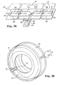
- FIGS. 2A and 2B respectively show a view of the carcass 11 supporting a receiving antenna 2 of a tire according to the invention and a section radial of the tire mounted on a rim 23.
- the receiving antenna 2 formed of several loop parts 2.1, 2.2 in a parallel mounting, is located as in the embodiment of Figures 1. But now it is connected to the object 10 by connection conductors 21 which exit from the complex 14 towards the inside of the tire, opposite the tread 16. They pass through the crown reinforcements 15, the carcass 11 and the internal sealing layer 17 before to project into the internal volume 22.
- the object 10 may be integral with the internal surface the tire (as in FIG. 2A) or else the rim 23 (as in FIG. 2B).
- the rim 23 is supported on a bead 26 which surrounds the tire in the lower part of the sidewall 27.
- a hole 24 is drilled through crown reinforcements 15, of the carcass 11 and of the sealing layer 17 superimposed, before present the complex 14.
- the connection conductors 21, individually covered with electrically insulating material, such as an elastomer, are inserted into the hole 24 during fitting in place of the complex 14 on the crown reinforcement 15.
- the hole 24 is then filled in with the interior with an elastomer, for example of the same nature as that of the inner layer seal 17.
- the tire can then be baked in the mold.
- FIG. 3A the antenna receiver 2 (or 2S) is shown unwound in a sandwich between the two sheets 13 of the complex 14.
- connection conductors 21 intended to connect the receiving antenna 2 to the object 10 will run in the sidewall 27 of the tire.
- Complex 14 has an extension 25 and the connection conductors 21 are located in the complex 14 at the level of the extension 25. When positioning the complex 14 on the carcass 11, the extension 25 is folded over the part of the carcass corresponding to the sidewall 27 of the tire.
- the object 10 can be implanted in any zone of the flank 27, either in the central part of the sidewall 27 as in FIG. 3C, ie closer to the tread 16, that is to say in the shoulder, or in the lower zone of the tire, as in FIG. 3B, at proximity of the bead 26 on which the rim bears (not shown).
- part of the loaded elastomer forming the outer flank 27.1 is rolled up to position the object 10 and connect it to the receiving antenna 2.
- the upturned part is then folded over the object 10 before baking in a mold.
- the antenna is such that the conductor 9 is arranged radially outward relative to the crown reinforcement tire.
- the antenna is such that the conductor 9 is disposed between the rubber inside and the carcass reinforcement of said tire, or even between the crown reinforcement and the carcass reinforcement of said tire.
- the variant of the 2S receiving antenna illustrated in the figure 3C comprises a conductor 9 arranged in one or more loops and having strands extending substantially circumferentially, said strands extending substantially circumferentially being arranged axially only in one or the other of the two zones lying between limits situated axially one at a distance of L / 6 from an axial end of said reinforcement vertex and the other at a distance of L / 3 from an axial end of said crown reinforcement.
- the antenna 2S has a “go” conductor positioned in the area preferential on the left.
- connection conductors 21 join the part of the antenna 2S receiver located on the left in the figure.
- the 2S antenna according to this variant comprises a “return” conductor positioned in the preferential zone right.
- the conductors connecting the left part to the right part are preferably arranged parallel to the axis of rotation of the tire, so as to only be subjected to stresses negligible when the tread is laid flat when passing through the contact area with the ground at each turn of the tire.
- Figures 3A and 3B although the appearance the antenna is very similar, the absence of any indication on the axial positioning of the antenna conductor means it can be any.
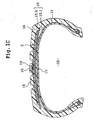
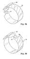
- the receiving antenna 2 can be installed in the sidewall 27 of the tire. This variant is illustrated in Figures 4. Note that this implantation in a side can also be useful with an antenna forming a single loop, in two nested C connected to each other.
- the complex 14 which includes the receiving antenna 2 sandwiched between two electrically insulating ring-shaped sheets 13.
- the receiving antenna 2 is formed of several loop parts 2.1, 2.2 arranged in a parallel mounting. In this example, two looped parts 2.1, 2.2 are shown. semicircular.
- the two sheets 13 can be similar to those described in FIG. 1A at thickness and composition point of view.
- the looped parts comprise two large portions 2a, 2b substantially in a portion of a circle, they follow the inner and outer edges of the sidewall 27.
- the spacing between the large portions 2a, 2b of the same part in a loop is substantially constant.
- the tall portions 2a, 2b are arranged so that their relative spacing disturbs as little as possible the tire rolling mechanics once it is finalized and vulcanized.
- the two big portions 2a, 2b of the same looped part are joined, at one end, by a small portion 4a which is shown directed substantially along a radius of the tire.
- the angle formed between the small portion 4a and the large portions 2a, 2b is substantially a right angle. It is well understood that this angle could be perfectly arbitrary and that the small portions could have an orientation other than radial with respect to the tire.
- a space 3 as small as possible separates from the side of the object 10, the two loop parts 2.1, 2.2.
- This space 3 is preferably less than about 1 centimeter.
- the lengths of the large portions 2a, 2b of the loop portions 2.1, 2.2 are chosen so that, when positioning the receiving antenna in the flank 27, between the carcass 11 and the outer sidewall 27.1 of the tire, the small portions 4a of each of the looped parts are close to each other while being in contact with each other.
- a space 5 less than about a centimeter separate them.
- the small portion 4a could measure about 2 to 4 centimeters and the large portions 2a, 2b of the order of a meter, the space 5 between the small portions 4a of the two looped parts could be worth between 0.1 and 0.5 cm per example.
- the elastomer loaded carrying the outer side 27.1 is placed on the carcass 11 without it adhering thereto. It is rolled up on the lower area of the tire in order to accommodate the complex 14 on the carcass 11 at the level of the area corresponding to the sidewall 27.1 of the tire, then folded down.
- the object 10 can be placed in the complex 14 between the two sheets 13 as in FIG. 4A or else being located outside the complex 14.
- one of the sheets 13 of the complex has an opening 20 to allow passage the conductors 21 for connecting the receiving antenna 2 to the object 10.
- object 10 is located outside the complex.
- the object 10 is located in the side 27 and more particularly in the shoulder of the tire while in FIG. 4C, it is still in the sidewall 27 but in the lower part of the tire. It is assumed in this figure that the sheet 13 located towards the outside of the tire has been removed to reveal the driver 9 taking the shape of a cable.
- FIG. 4D the object 10 is located in the apex zone 28 of the pneumatic under the tread (not shown).
- Complex 14 suitable for this embodiment is shown in Figure 4E. It behaves similarly to that of the FIG. 3A an extension 25 in which the conductors 21 of connection of the receiving antenna 2 to object 10.
- the extension 25 When placing complex 14 on the carcass at an area corresponding to the sidewall of the tire, the extension 25 is folded down on the crown reinforcement which surround the carcass 11 at the top of the tire. The tread can then be brought back and the outer sides folded down.
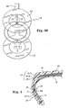
- FIG. 5 yet another variant of the layout of object 10, the receiving antenna 2 being always located in the sidewall 27 of the tire.
- the object 10 is located in the internal volume 22 delimited by the tire. It is secured to the inner surface of the tire. It could be attached to the rim as on Figure 2B.
- a hole 24 has been drilled through the carcass 11 and the sealing layer 17 superimposed, before installing the complex 14.
- the conductors of connection 21, individually covered with electrically insulating material, such as a elastomer, are inserted into the hole 24 when the complex 14 is placed on the carcass 11.
- the hole 24 is then filled from the inside with an elastomer little or not loaded with conductive charges, for example of the same kind as that of the internal sealing layer 17.
- the tire can be molded and baked.
- At least one electronic circuit 70 can cooperate with the object 10. It can have an amplification or shaping function for example. This electronic circuit may not not be secured to the sensor and be connected between the receiving antenna 2 and the object 10. All or part of the electronic circuit can be located in the tire.
- FIG. 6A we have shown a partial cross section of a tire according to the invention. This last one is equipped with a receiving antenna 2 located under the tread 16, a circuit electronics 70 located in the sidewall 27 of the tire in the central part of the latter and of an object 10 also in the side 27 but in its lower part.
- the antenna receiver 2 is located in the sidewall 27 of the tire
- the electronic circuit 70 is located also in the flank 27 near the connection between the loop parts 2.1, 2.2 of the receiving antenna 2 and the object 10 is located in the crown area 28 of the tire.
- the electronic circuit 70 could be placed between the two sheets 13 of the complex. We could also consider placing the electronic circuit 70 in the internal volume 22 delimited by the pneumatic.
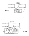
- FIGS. 7A, 7B The parts 2.1, 2.2 are shown flattened to simplify the drawing.
- the connection is made via the electronic circuit 6 which can have a rectifier function.
- This electronic circuit 6 can comprise a single rectification circuit 60 as in FIG. 7A or several 60.1, 60.2 as in FIG. 7B.
- Parallel connection is made before signal level rectification induced in the receiving antenna.
- each loop part 2.1, 2.2 is connected to the input of a its own rectification circuit, namely 60.1, 60.2 and the outputs of the circuits respectively of rectification cooperate in series with object 10 so that it receives the sum of voltages present at the output of the various rectification circuits 60.1, 60.2.
- object 10 receives the sum of voltages present at the output of the various rectification circuits 60.1, 60.2.
- FIG. 7A The configuration of FIG. 7A with a single rectification circuit 60 is more interesting from the cost and space point of view but also from the point of view robustness to disturbances. It is better to make a single transformation on a sum signal that several followed by a summons.
- looped parts do not need to be closed, i.e. the two ends of the looped parts do not need to be connected electrically to the object, a connection with only one of these ends is sufficient.
- the capacities parasites due to the environment ensure the looping of the looped part on the object.
- the Figures 7C and 7D illustrate such a configuration.
- Each of the looping parts 2.1, 2.2 has one end "in the air” and one end connected to the electronic circuit 6.
- Capacities parasites are shown schematically in dotted lines.
- the present invention is not limited to the forms of receiving antennas presented, several objects can be connected to the same receiving antenna, the latter being remote controlled from the emitting device through the receiving antenna. They can be located at different places, it can be envisaged that each of the sides is provided with at least one object.
Abstract
Description
- préparation d'une carcasse,
- préparation d'un complexe comportant une antenne réceptrice morcelée en plusieurs parties en boucle agencées en un montage parallèle, cette antenne réceptrice étant immobilisée entre deux feuilles d'un matériau électriquement isolant, préférentiellement en matériau élastomère non vulcanisé, compatible avec les matériaux habituels du pneumatique, en prévoyant une liaison avec au moins un objet destiné à être télécontrôlé par couplage électromagnétique entre l'antenne réceptrice et au moins une antenne émissive,
- pose du complexe sur la carcasse,
- recouvrement du complexe par un élastomère chargé et finition de manière à obtenir un pneumatique cru,
- moulage et vulcanisation du pneumatique cru.
Claims (36)
- Pneumatique équipé d'au moins une antenne réceptrice (2) d'un dispositif de réception (1) qui inclut un objet (10) destiné à être télécontrôlé par couplage électromagnétique avec au moins une antenne émissive (8), cette antenne réceptrice (2) étant destinée à être reliée à l'objet (10), caractérisé en ce que l'antenne réceptrice (2) est morcelée en plusieurs parties en boucle (2.1, 2.2) agencées en un montage parallèle, ces parties en boucle (2.1, 2.2) ayant chacune une surface (s1, s2), ces surfaces (s1, s2) étant globalement juxtaposées de manière à ce que les parties en boucle (2.1, 2.2) se couplent successivement et continûment à l'antenne émissive (8).
- Pneumatique selon la revendication 1, caractérisé en ce que l'antenne réceptrice (2) possède une surface utile de réception (s) qui est sensiblement égale à la somme des surfaces (s1, s2) de toutes les parties en boucle (2.1, 2.2).
- Pneumatique selon l'une des revendications 1 ou 2, caractérisé en ce que les parties en boucle (2.1, 2.2) sont formées d'un conducteur (9), une portion (4a) de conducteur d'une première partie en boucle (2.1) et une portion (4a) de conducteur d'une seconde partie en boucle (2.2) voisine de la première partie en boucle (2.1) étant séparées par un espace (5) aussi faible que possible.
- Pneumatique selon l'une des revendications 1 à 3, caractérisé en ce que deux parties en boucle (2.1, 2.2) sont séparées, du côté de l'objet (10), par un espace (3) aussi faible que possible.
- Pneumatique selon l'une des revendications 1 à 4, caractérisé en ce qu'un condensateur d'accord (c1, c2) est monté en parallèle avec au moins une des parties en boucle (2.1, 2.2) pour accorder la dite partie en boucle (2.1, 2.2) sur l'antenne émissive (8).
- Pneumatique selon l'une des revendications 1 à 5, caractérisé en ce que l'antenne réceptrice (2) est immobilisée entre deux feuilles (13) d'un matériau électriquement isolant pour former un complexe (14), ce complexe (14) étant implanté dans le pneumatique.
- Pneumatique selon la revendication 6, comportant, dans une zone de sommet (28), au moins une armature de sommet (15.1, 15.2, 15.3) entourée par une bande de roulement (16), caractérisé en ce que le complexe (14) est inséré entre la armature de sommet (15.1, 15.2, 15.3) et la bande de roulement (16).
- Pneumatique selon la revendication 7, caractérisé en ce que les feuilles (13) du complexe (14) sont réalisées dans un matériau ayant des propriétés mécaniques proches de celles de la bande de roulement (16).
- Pneumatique selon l'une des revendications 3 à 8, caractérisé en ce que ledit conducteur (9) est disposé entre la gomme intérieure et ladite armature de carcasse dudit pneumatique.
- Pneumatique selon l'une des revendications 3 à 8, caractérisé en ce que ledit conducteur (9) est disposé entre ladite armature de sommet et ladite armature de carcasse dudit pneumatique.
- Pneumatique selon l'une des revendications 3 à 8, caractérisé en ce que ledit conducteur (9) est disposé radialement extérieurement relativement à ladite armature de sommet..
- Pneumatique selon l'une des revendications 7 à 11, dans lequel ladite armature de ceinture s'étend axialement sur une distance L, caractérisé en ce que l'antenne réceptrice (2S) comprend un conducteur (9) disposé en une ou plusieurs boucles et ayant des brins s'étendant sensiblement circonférentiellement, lesdits brins s'étendant sensiblement circonférentiellement étant disposés axialement uniquement dans l'une ou l'autre des deux zones comprises entre des limites situées axialement l'une à une distance de L/6 d'une extrémité axiale de ladite armature de sommet et l'autre à une distance de L/3 d'une extrémité axiale de ladite armature de sommet.
- Pneumatique selon la revendication 6, comportant une carcasse (11) recouverte, vers l'extérieur du pneumatique, d'un flanc extérieur (27.1), caractérisé en ce que le complexe (14) est inséré entre la carcasse (11) et le flanc extérieur (27.1).
- Pneumatique selon l'une des revendications 6 à 13, caractérisé en ce que les feuilles (13) sont réalisées dans un élastomère chargé en silice et en noir de carbone, ce matériau étant peu chargé en noir de carbone de manière à le rendre électriquement isolant.
- Pneumatique selon l'une des revendications 1 à 14, caractérisé en ce que les parties en boucle (2.1, 2.2) sont réalisées avec un conducteur (9) métallique nu.
- Pneumatique selon la revendication 15, caractérisé en ce que le conducteur (9) comporte un ou plusieurs fils.
- Pneumatique selon l'une des revendications 15 ou 16, comportant des fils de renforcement, caractérisé en ce que le conducteur (9) comporte un ou plusieurs fils de même nature que les fils de renforcement.
- Pneumatique selon l'une des revendications 15 à 17, caractérisé en ce que le conducteur (9) comporte un ou plusieurs fils en acier laitonné en surface.
- Pneumatique selon l'une des revendications 15 à 18, caractérisé en ce que le conducteur (9) est ondulé.
- Pneumatique selon l'une des revendications 15 à 19 pour autant qu'elles dépendent de la revendication 6, caractérisé en ce que le conducteur (9) est collé à au moins une des feuilles (13) du complexe (14).
- Pneumatique selon l'une des revendications 1 à 20, caractérisé en ce qu'il est équipé de l'objet (10).
- Pneumatique selon l'une des revendications 1 à 21, caractérisé en ce qu'il est équipé d'un circuit électronique (70) qui coopère avec l'objet (10).
- Pneumatique selon la revendication 22, caractérisé en ce que le circuit électronique comporte un circuit redresseur unique (60), les parties en boucle (2.1, 2.2) ayant au moins une extrémité reliée en entrée du circuit redresseur (60), l'objet (10) étant relié en sortie du circuit redresseur (60).
- Pneumatique selon la revendication 22, caractérisé en ce que le circuit électronique comporte plusieurs circuits redresseurs (60.1, 60.2), chaque partie en boucle ayant au moins une extrémité reliée en entrée d'un circuit redresseur (60.1, 60.2), les circuits redresseurs ayant leurs sorties reliées en série avec l'objet (10).
- Pneumatique selon l'une des revendications 21 à 24, comportant une zone de sommet (28), caractérisé en ce que l'objet (10) et/ou le circuit électronique (70) est/sont localisé(s) dans la zone de sommet (28).
- Pneumatique selon l'une des revendications 21 à 25, comportant un flanc (27), caractérisé en ce que l'objet (10) et/ou le circuit électronique (70) est/sont localisé(s) dans le flanc (27).
- Pneumatique selon l'une des revendications 21 à 26, délimitant un volume interne (22), caractérisé en ce que l'objet (10) et/ou le circuit électronique (70) est/sont localisé(s) dans le volume interne (22).
- Pneumatique selon l'une des revendications 21 à 27 pour autant qu'elles dépendent de la revendication 6, caractérisé en ce que l'objet et/ou le circuit électronique est/sont localisé(s) dans le complexe (14).
- Pneumatique selon l'une des revendications 1 à 28, caractérisé en ce que l'objet (10) comporte au moins un élément du groupe formé d'un capteur, d'un compteur, d'une étiquette électronique.
- Procédé de réalisation d'un pneumatique comportant les étapes suivantes :préparation d'une carcasse (11),préparation d'un complexe (14) comportant une antenne réceptrice (2) morcelée en plusieurs parties en boucle (2.1, 2.2) agencées en un montage parallèle, cette antenne réceptrice étant immobilisée entre deux feuilles (13) d'un matériau électriquement isolant, préférentiellement en matériau élastomère non vulcanisé, compatible avec les matériaux habituels du pneumatique, en prévoyant une liaison (21) avec au moins un objet (10) destiné à être télécontrôlé par couplage électromagnétique entre l'antenne réceptrice (2) et au moins une antenne émissive (8),pose du complexe (14) sur la carcasse (11),recouvrement du complexe (14) par un élastomère chargé et finition de manière à obtenir un pneumatique cru,moulage et vulcanisation du pneumatique cru.
- Procédé selon la revendication 30, caractérisé en ce que l'élastomère chargé forme une bande de roulement (16) du pneumatique.
- Procédé selon l'une des revendications 26 ou 27, caractérisé en ce que l'élastomère chargé contribue à former un flanc (27) du pneumatique.
- Procédé selon l'une des revendications 26 à 28, caractérisé en ce qu'il comporte une étape de pose d'au moins une armature de sommet (15) sur la carcasse (11) avant la pose du complexe (14).
- Procédé selon l'une des revendications 30 à 33, caractérisé en ce qu'il comporte une étape de forage dans la carcasse (11) d'un trou (24) débouchant dans un volume interne (22) délimité par le pneumatique, ce trou (24) étant destiné à contenir des conducteurs de connexion (21) pour la liaison entre l'antenne réceptrice (2) et l'objet (10), l'objet se trouvant dans le volume interne (22).
- Procédé selon la revendication 34, caractérisé en ce que l'étape de forage est suivie d'une étape de rebouchage avant cuisson, par l'intérieur du pneumatique, du trou (24) foré contenant les conducteurs (21).
- Procédé selon l'une des revendications 30 à 35, caractérisé en ce que l'étape de préparation du complexe (14) inclut la réalisation d'au moins une extension (25) dans laquelle sont immobilisés des conducteurs de connexion (21) pour la liaison entre l'antenne réceptrice (2) et l'objet (10), cette extension (25) étant rabattue sur un flanc (27) du pneumatique lorsque le complexe (14) est posé sur une zone de sommet (28) du pneumatique ou sur la zone de sommet (28) lorsque le complexe (14) est posé sur le flanc (27).
Applications Claiming Priority (2)
| Application Number | Priority Date | Filing Date | Title |
|---|---|---|---|
| FR0204064A FR2837748A1 (fr) | 2002-04-02 | 2002-04-02 | Pneumatique dote d'une antenne receptrice |
| FR0204064 | 2002-04-02 |
Publications (2)
| Publication Number | Publication Date |
|---|---|
| EP1350640A1 true EP1350640A1 (fr) | 2003-10-08 |
| EP1350640B1 EP1350640B1 (fr) | 2008-02-13 |
Family
ID=27839372
Family Applications (1)
| Application Number | Title | Priority Date | Filing Date |
|---|---|---|---|
| EP03006543A Expired - Lifetime EP1350640B1 (fr) | 2002-04-02 | 2003-03-24 | Pneumatique doté d'une antenne réceptrice |
Country Status (8)
| Country | Link |
|---|---|
| US (1) | US6991013B2 (fr) |
| EP (1) | EP1350640B1 (fr) |
| JP (1) | JP2004001716A (fr) |
| CN (1) | CN1313292C (fr) |
| AT (1) | ATE385915T1 (fr) |
| BR (1) | BR0300995A (fr) |
| DE (1) | DE60319027T2 (fr) |
| FR (1) | FR2837748A1 (fr) |
Cited By (10)
| Publication number | Priority date | Publication date | Assignee | Title |
|---|---|---|---|---|
| FR2870397A1 (fr) * | 2004-05-13 | 2005-11-18 | Michelin Soc Tech | Cablage pour article en caoutchouc avec electronique integree et procede pour instrumenter un tel article |
| EP1977941A1 (fr) | 2007-04-06 | 2008-10-08 | Societe de Technologie Michelin | Procédé d'estimation d'une hauteur d'eau au contact d'un pneumatique sur une chaussée |
| EP1977940A1 (fr) | 2007-04-06 | 2008-10-08 | Societe de Technologie Michelin | Procédé de détection d'un phénomène d'hydroplanage d'un pneumatique sur une chaussée |
| EP1977942A1 (fr) | 2007-04-06 | 2008-10-08 | Societe de Technologie Michelin | Procédé de détection et d'estimation d'un phénomène d'hydroplanage d'un pneumatique sur une chaussée mouillée |
| EP2015206A1 (fr) | 2007-07-04 | 2009-01-14 | Société de Technologie MICHELIN | Procédé d' estimation de la marge d'adhérence disponible d'un pneumatique en roulage |
| US7543490B2 (en) | 2005-05-04 | 2009-06-09 | Michelin Recherche Et Technique S.A. | Tire comprising a force measuring device having a rigid stem |
| US8151127B2 (en) | 2000-07-26 | 2012-04-03 | Bridgestone Americas Tire Operations, Llc | System for conserving battery life in a battery operated device |
| US8266465B2 (en) | 2000-07-26 | 2012-09-11 | Bridgestone Americas Tire Operation, LLC | System for conserving battery life in a battery operated device |
| WO2017120979A1 (fr) * | 2016-01-15 | 2017-07-20 | 田艺儿 | Anneau de verrouillage à fonction d'identification par radiofréquence rfid |
| EP3838631A1 (fr) * | 2019-12-17 | 2021-06-23 | The Goodyear Tire & Rubber Company | Unité de capteur de pneumatique flexible et pneumatique |
Families Citing this family (36)
| Publication number | Priority date | Publication date | Assignee | Title |
|---|---|---|---|---|
| FR2837985B1 (fr) * | 2002-04-02 | 2004-05-21 | Commissariat Energie Atomique | Antenne receptrice morcelee |
| US7009576B2 (en) * | 2002-06-11 | 2006-03-07 | Michelin Recherche Et Technique S.A. | Radio frequency antenna for a tire and method for same |
| JP4922561B2 (ja) * | 2002-12-23 | 2012-04-25 | ブリヂストン アメリカズ タイヤ オペレイションズ エルエルシー | タグを具えるタイヤ |
| JP4331528B2 (ja) * | 2003-07-29 | 2009-09-16 | 株式会社ブリヂストン | 空気入りラジアルタイヤの製造方法およびその製造方法を用いて製造された空気入りラジアルタイヤ |
| US20050257868A1 (en) * | 2004-05-21 | 2005-11-24 | Adamson John D | Process and device for incorporating electronics into a tire |
| US7353720B2 (en) | 2004-07-09 | 2008-04-08 | Michelin Recherche Et Technique, S.A. | Bridge patch for electromechanical transducer elements in tire assemblies |
| FR2875737B1 (fr) * | 2004-09-29 | 2008-07-04 | Michelin Soc Tech | Pneumatique pour vehicule et procede d'aide a la conduite d'un vehicule |
| ATE389550T1 (de) * | 2004-11-05 | 2008-04-15 | Pirelli | Luftreifen mit antenne für fahrzeugräder und herstellungsverfahren dafür |
| FR2883222B1 (fr) * | 2005-03-21 | 2007-05-18 | Michelin Soc Tech | Procede d'obtention d'un fil preforme destine a etre integre lors de la fabrication d'un pneummatique, ensemble d'une feuille de gomme et d'un fil preforme |
| JP4686603B2 (ja) * | 2005-06-22 | 2011-05-25 | パーデュ リサーチ ファンデーション | 一体的な寿命検出能力を有する構造 |
| JP4794368B2 (ja) * | 2006-06-16 | 2011-10-19 | 株式会社ブリヂストン | タイヤ変形量計測装置 |
| JP2008195189A (ja) * | 2007-02-13 | 2008-08-28 | Mitomo Shoji Kk | タイヤ |
| US7716977B2 (en) * | 2008-07-21 | 2010-05-18 | The Goodyear Tire & Rubber Company | Tire sensor system and method |
| FR2936185B1 (fr) * | 2008-09-25 | 2011-09-23 | Michelin Soc Tech | Pneumatique muni d'un organe a antenne deportee |
| FR2983609B1 (fr) * | 2011-12-02 | 2014-02-07 | Michelin Soc Tech | Ensemble electronique destine a etre integre dans un pneumatique |
| JP2013126838A (ja) * | 2011-12-19 | 2013-06-27 | Toppan Forms Co Ltd | タイヤ |
| CN102795062B (zh) * | 2012-08-29 | 2015-04-08 | 河北永发耐磨拉轮胎制造有限公司 | 一种防爆轮胎及制造该防爆轮胎的方法 |
| CN103715511B (zh) * | 2013-12-31 | 2015-07-15 | 成都信息工程学院 | 一种微带标签天线 |
| KR20180084113A (ko) * | 2015-12-24 | 2018-07-24 | 미츠비시 쥬고 기카이 시스템 가부시키가이샤 | 타이어 특성값 계측 장치 및 타이어 특성값 계측 시스템 |
| FR3059592A1 (fr) | 2016-12-05 | 2018-06-08 | Compagnie Generale Des Etablissements Michelin | Procede de fabrication d'un patch equipe d'un transpondeur radiofrequence et pneumatique comportant un tel patch |
| FR3059604A1 (fr) | 2016-12-05 | 2018-06-08 | Compagnie Generale Des Etablissements Michelin | Enveloppe pneumatique equipee d'un organe electronique |
| FR3059607A1 (fr) | 2016-12-05 | 2018-06-08 | Compagnie Generale Des Etablissements Michelin | Module de communication radiofrequence pour pneumatique |
| FR3059605A1 (fr) | 2016-12-05 | 2018-06-08 | Compagnie Generale Des Etablissements Michelin | Enveloppe pneumatique equipee d''un organe electronique |
| FR3059606A1 (fr) | 2016-12-05 | 2018-06-08 | Compagnie Generale Des Etablissements Michelin | Module de communication radiofrequence pour pneumatique |
| FR3059603A1 (fr) | 2016-12-07 | 2018-06-08 | Compagnie Generale Des Etablissements Michelin | Pneumatique adapte pour roulage a plat equipe d’un organe electronique |
| EP3424753B1 (fr) * | 2017-07-03 | 2019-06-26 | Nokian Renkaat Oyj | Un pneu avec un indicateur sans fil |
| FR3073094B1 (fr) * | 2017-10-27 | 2021-01-29 | Michelin & Cie | Systeme de mesure de parametre d'un ensemble monte |
| DE102018200103A1 (de) * | 2018-01-05 | 2019-07-11 | Continental Reifen Deutschland Gmbh | Reifenbauteil für einen Reifenrohling |
| FR3081774B1 (fr) * | 2018-05-29 | 2020-08-07 | Michelin & Cie | Enveloppe pneumatique equipee d'un systeme de mesure et methode de communication d'un tel assemblage |
| JP7173141B2 (ja) | 2018-06-22 | 2022-11-16 | 横浜ゴム株式会社 | 空気入りタイヤおよびアセンブリシート |
| CN112469577A (zh) * | 2018-07-24 | 2021-03-09 | 横滨橡胶株式会社 | 充气轮胎及其制造方法 |
| JP6582106B1 (ja) * | 2018-10-03 | 2019-09-25 | Toyo Tire株式会社 | タイヤの製造方法 |
| EP3900947A4 (fr) * | 2018-12-17 | 2022-08-17 | Bridgestone Corporation | Pneu, dispositif d'alimentation de véhicule et corps mobile |
| DE102019205298A1 (de) * | 2019-04-12 | 2020-10-15 | Continental Reifen Deutschland Gmbh | Reifen |
| CN112373247B (zh) * | 2020-10-12 | 2022-10-14 | 东风汽车集团有限公司 | 一种车胎状态预警方法及装置 |
| US11865872B2 (en) * | 2020-11-02 | 2024-01-09 | Tdk Corporation | Interconnects for electrical components positioned adjacent to vehicle tires |
Citations (3)
| Publication number | Priority date | Publication date | Assignee | Title |
|---|---|---|---|---|
| FR2771965A1 (fr) | 1997-12-08 | 1999-06-11 | Dassault Electronique | Pneumatique muni d'une boucle conductrice et procede d'implantation de cette boucle sous sa bande de roulement |
| WO1999029522A1 (fr) * | 1997-12-09 | 1999-06-17 | The Goodyear Tire & Rubber Company | Pneumatique muni d'une antenne pour repeteur radio |
| WO1999029525A1 (fr) * | 1997-12-09 | 1999-06-17 | The Goodyear Tire & Rubber Company | Antenne pour repondeur radio |
Family Cites Families (18)
| Publication number | Priority date | Publication date | Assignee | Title |
|---|---|---|---|---|
| US44096A (en) * | 1864-09-06 | Improvement in cider-mills | ||
| US41258A (en) * | 1864-01-12 | Improvement in planes for jointing table-leaves | ||
| US90434A (en) * | 1869-05-25 | of scran ton | ||
| US90424A (en) * | 1869-05-25 | Improvement in cream-fttmf | ||
| DE468513C (de) | 1927-07-05 | 1928-11-14 | Paul Rinkel Dipl Ing | Rahmenantenne mit zwei oder mehr Wicklungsgruppen |
| JPS61196080A (ja) * | 1985-02-21 | 1986-08-30 | 日産自動車株式会社 | 無線式利用者識別装置 |
| EP0578701B1 (fr) | 1991-04-03 | 1999-10-20 | Integrated Silicon Design Pty. Ltd | Systeme de tri d'articles |
| GB9220413D0 (en) * | 1992-09-28 | 1992-11-11 | Texas Instruments Holland | An antenna system |
| US5541574A (en) * | 1993-12-22 | 1996-07-30 | Palomar Technologies Corporation | Transponder system for communicating with a vehicle tire |
| US5825291A (en) * | 1996-04-10 | 1998-10-20 | Sentry Technology Corporation | Electronic article surveillance system |
| US6025807A (en) * | 1999-03-12 | 2000-02-15 | Lucent Technologies, Inc. | Orientation independent loop antenna |
| US6195009B1 (en) * | 1999-11-15 | 2001-02-27 | Hector Irizarry | Child monitoring device adapted for use with an electronic surveillance system |
| US6356243B1 (en) | 2000-07-19 | 2002-03-12 | Logitech Europe S.A. | Three-dimensional geometric space loop antenna |
| US6696954B2 (en) | 2000-10-16 | 2004-02-24 | Amerasia International Technology, Inc. | Antenna array for smart RFID tags |
| US6630910B2 (en) * | 2001-10-29 | 2003-10-07 | Marconi Communications Inc. | Wave antenna wireless communication device and method |
| US6927741B2 (en) | 2001-11-15 | 2005-08-09 | Merlin Technology, Inc. | Locating technique and apparatus using an approximated dipole signal |
| JP2003152442A (ja) | 2001-11-15 | 2003-05-23 | Alps Electric Co Ltd | 受信アンテナの配置方法 |
| FR2837985B1 (fr) * | 2002-04-02 | 2004-05-21 | Commissariat Energie Atomique | Antenne receptrice morcelee |
-
2002
- 2002-04-02 FR FR0204064A patent/FR2837748A1/fr active Pending
-
2003
- 2003-03-24 AT AT03006543T patent/ATE385915T1/de not_active IP Right Cessation
- 2003-03-24 EP EP03006543A patent/EP1350640B1/fr not_active Expired - Lifetime
- 2003-03-24 DE DE60319027T patent/DE60319027T2/de not_active Expired - Fee Related
- 2003-04-01 BR BR0300995-5A patent/BR0300995A/pt not_active Application Discontinuation
- 2003-04-01 US US10/404,844 patent/US6991013B2/en not_active Expired - Fee Related
- 2003-04-02 CN CNB031090818A patent/CN1313292C/zh not_active Expired - Fee Related
- 2003-04-02 JP JP2003099599A patent/JP2004001716A/ja not_active Ceased
Patent Citations (3)
| Publication number | Priority date | Publication date | Assignee | Title |
|---|---|---|---|---|
| FR2771965A1 (fr) | 1997-12-08 | 1999-06-11 | Dassault Electronique | Pneumatique muni d'une boucle conductrice et procede d'implantation de cette boucle sous sa bande de roulement |
| WO1999029522A1 (fr) * | 1997-12-09 | 1999-06-17 | The Goodyear Tire & Rubber Company | Pneumatique muni d'une antenne pour repeteur radio |
| WO1999029525A1 (fr) * | 1997-12-09 | 1999-06-17 | The Goodyear Tire & Rubber Company | Antenne pour repondeur radio |
Cited By (15)
| Publication number | Priority date | Publication date | Assignee | Title |
|---|---|---|---|---|
| US8266465B2 (en) | 2000-07-26 | 2012-09-11 | Bridgestone Americas Tire Operation, LLC | System for conserving battery life in a battery operated device |
| US8151127B2 (en) | 2000-07-26 | 2012-04-03 | Bridgestone Americas Tire Operations, Llc | System for conserving battery life in a battery operated device |
| WO2005113262A1 (fr) * | 2004-05-13 | 2005-12-01 | Societe De Technologie Michelin | Cablage et procede pour instrumenter un pneumatique ou une articulation antivibratoire ou un appui de securite de la liaison au sol pour vehicule |
| FR2870397A1 (fr) * | 2004-05-13 | 2005-11-18 | Michelin Soc Tech | Cablage pour article en caoutchouc avec electronique integree et procede pour instrumenter un tel article |
| US7543490B2 (en) | 2005-05-04 | 2009-06-09 | Michelin Recherche Et Technique S.A. | Tire comprising a force measuring device having a rigid stem |
| EP1977940A1 (fr) | 2007-04-06 | 2008-10-08 | Societe de Technologie Michelin | Procédé de détection d'un phénomène d'hydroplanage d'un pneumatique sur une chaussée |
| US7694556B2 (en) | 2007-04-06 | 2010-04-13 | Michelin Recherche Et Technique S.A. | Method of detecting hydroplaning and estimating an intensity of hydroplaning of a tire on a wet road |
| US7739905B2 (en) | 2007-04-06 | 2010-06-22 | Michelin Recherche Et Technique S.A. | Method of estimating a height of water in contact with a tire on a road |
| US7832262B2 (en) | 2007-04-06 | 2010-11-16 | Michelin Recherche Et Technique S.A. | Method of detecting an occurrence of hydroplaning of a tire on a road |
| EP1977942A1 (fr) | 2007-04-06 | 2008-10-08 | Societe de Technologie Michelin | Procédé de détection et d'estimation d'un phénomène d'hydroplanage d'un pneumatique sur une chaussée mouillée |
| EP1977941A1 (fr) | 2007-04-06 | 2008-10-08 | Societe de Technologie Michelin | Procédé d'estimation d'une hauteur d'eau au contact d'un pneumatique sur une chaussée |
| EP2015206A1 (fr) | 2007-07-04 | 2009-01-14 | Société de Technologie MICHELIN | Procédé d' estimation de la marge d'adhérence disponible d'un pneumatique en roulage |
| US8392089B2 (en) | 2007-07-04 | 2013-03-05 | Michelin Recherche Et Technique S.A. | Method of estimating an available grip margin of a tire when rolling |
| WO2017120979A1 (fr) * | 2016-01-15 | 2017-07-20 | 田艺儿 | Anneau de verrouillage à fonction d'identification par radiofréquence rfid |
| EP3838631A1 (fr) * | 2019-12-17 | 2021-06-23 | The Goodyear Tire & Rubber Company | Unité de capteur de pneumatique flexible et pneumatique |
Also Published As
| Publication number | Publication date |
|---|---|
| ATE385915T1 (de) | 2008-03-15 |
| CN1448284A (zh) | 2003-10-15 |
| FR2837748A1 (fr) | 2003-10-03 |
| CN1313292C (zh) | 2007-05-02 |
| US20030217797A1 (en) | 2003-11-27 |
| DE60319027D1 (de) | 2008-03-27 |
| EP1350640B1 (fr) | 2008-02-13 |
| US6991013B2 (en) | 2006-01-31 |
| DE60319027T2 (de) | 2009-01-29 |
| BR0300995A (pt) | 2004-08-17 |
| JP2004001716A (ja) | 2004-01-08 |
Similar Documents
| Publication | Publication Date | Title |
|---|---|---|
| EP1350640B1 (fr) | Pneumatique doté d'une antenne réceptrice | |
| EP3551480B1 (fr) | Pneumatique adapté pour roulage à plat equipé d'un organe electronique | |
| EP3548312B1 (fr) | Module de communication radiofréquence pour pneumatique | |
| EP3548314B1 (fr) | Enveloppe pneumatique équipée d'un organe électronique | |
| EP3548316B1 (fr) | Module de communication radiofréquence pour pneumatique | |
| EP3548313B1 (fr) | Enveloppe pneumatique équipée d'un organe électronique | |
| WO2005113262A1 (fr) | Cablage et procede pour instrumenter un pneumatique ou une articulation antivibratoire ou un appui de securite de la liaison au sol pour vehicule | |
| EP3793812B1 (fr) | Procede de fabrication d'un pneumatique equipe d'un module de communication radiofrequence | |
| EP3642054B1 (fr) | Pneumatique adapte pour roulage a plat equipe d'un organe electronique | |
| FR3067975B1 (fr) | Pneumatique adapte pour roulage a plat equipe d'un organe electronique | |
| EP4035073A1 (fr) | Pneumatique equipe d'un transpondeur radiofrequence | |
| EP4035075A1 (fr) | Pneumatique equipe d'un transpondeur radiofrequence | |
| EP4069525A1 (fr) | Pneumatique equipe d'un transpondeur radiofrequence | |
| WO2021058904A1 (fr) | Pneumatique equipe d'un transpondeur radiofrequence | |
| FR2966768A1 (fr) | Procede de fabrication d'un pneumatique comprenant un ensemble electronique | |
| EP4201712A1 (fr) | Pneumatique équipée d'un dispositif d'émission-réception radiofréquence | |
| EP3662535A1 (fr) | Antenne pour organe electronique d'un pneumatique |
Legal Events
| Date | Code | Title | Description |
|---|---|---|---|
| PUAI | Public reference made under article 153(3) epc to a published international application that has entered the european phase |
Free format text: ORIGINAL CODE: 0009012 |
|
| AK | Designated contracting states |
Kind code of ref document: A1 Designated state(s): AT BE BG CH CY CZ DE DK EE ES FI FR GB GR HU IE IT LI LU MC NL PT RO SE SI SK TR |
|
| AX | Request for extension of the european patent |
Extension state: AL LT LV MK |
|
| 17P | Request for examination filed |
Effective date: 20040408 |
|
| AKX | Designation fees paid |
Designated state(s): AT BE BG CH CY CZ DE DK EE ES FI FR GB GR HU IE IT LI LU MC NL PT RO SE SI SK TR |
|
| GRAP | Despatch of communication of intention to grant a patent |
Free format text: ORIGINAL CODE: EPIDOSNIGR1 |
|
| GRAS | Grant fee paid |
Free format text: ORIGINAL CODE: EPIDOSNIGR3 |
|
| GRAA | (expected) grant |
Free format text: ORIGINAL CODE: 0009210 |
|
| AK | Designated contracting states |
Kind code of ref document: B1 Designated state(s): AT BE BG CH CY CZ DE DK EE ES FI FR GB GR HU IE IT LI LU MC NL PT RO SE SI SK TR |
|
| REG | Reference to a national code |
Ref country code: GB Ref legal event code: FG4D Free format text: NOT ENGLISH |
|
| REG | Reference to a national code |
Ref country code: CH Ref legal event code: EP |
|
| REG | Reference to a national code |
Ref country code: IE Ref legal event code: FG4D Free format text: LANGUAGE OF EP DOCUMENT: FRENCH |
|
| REF | Corresponds to: |
Ref document number: 60319027 Country of ref document: DE Date of ref document: 20080327 Kind code of ref document: P |
|
| PG25 | Lapsed in a contracting state [announced via postgrant information from national office to epo] |
Ref country code: FI Free format text: LAPSE BECAUSE OF FAILURE TO SUBMIT A TRANSLATION OF THE DESCRIPTION OR TO PAY THE FEE WITHIN THE PRESCRIBED TIME-LIMIT Effective date: 20080213 Ref country code: ES Free format text: LAPSE BECAUSE OF FAILURE TO SUBMIT A TRANSLATION OF THE DESCRIPTION OR TO PAY THE FEE WITHIN THE PRESCRIBED TIME-LIMIT Effective date: 20080524 |
|
| NLV1 | Nl: lapsed or annulled due to failure to fulfill the requirements of art. 29p and 29m of the patents act | ||
| PG25 | Lapsed in a contracting state [announced via postgrant information from national office to epo] |
Ref country code: AT Free format text: LAPSE BECAUSE OF FAILURE TO SUBMIT A TRANSLATION OF THE DESCRIPTION OR TO PAY THE FEE WITHIN THE PRESCRIBED TIME-LIMIT Effective date: 20080213 |
|
| BERE | Be: lapsed |
Owner name: MICHELIN RECHERCHE ET TECHNIQUE S.A. Effective date: 20080331 Owner name: SOC. DE TECHNOLOGIE MICHELIN Effective date: 20080331 |
|
| PG25 | Lapsed in a contracting state [announced via postgrant information from national office to epo] |
Ref country code: SI Free format text: LAPSE BECAUSE OF FAILURE TO SUBMIT A TRANSLATION OF THE DESCRIPTION OR TO PAY THE FEE WITHIN THE PRESCRIBED TIME-LIMIT Effective date: 20080213 |
|
| REG | Reference to a national code |
Ref country code: IE Ref legal event code: FD4D |
|
| PG25 | Lapsed in a contracting state [announced via postgrant information from national office to epo] |
Ref country code: SK Free format text: LAPSE BECAUSE OF FAILURE TO SUBMIT A TRANSLATION OF THE DESCRIPTION OR TO PAY THE FEE WITHIN THE PRESCRIBED TIME-LIMIT Effective date: 20080213 Ref country code: PT Free format text: LAPSE BECAUSE OF FAILURE TO SUBMIT A TRANSLATION OF THE DESCRIPTION OR TO PAY THE FEE WITHIN THE PRESCRIBED TIME-LIMIT Effective date: 20080714 Ref country code: MC Free format text: LAPSE BECAUSE OF NON-PAYMENT OF DUE FEES Effective date: 20080331 Ref country code: IE Free format text: LAPSE BECAUSE OF FAILURE TO SUBMIT A TRANSLATION OF THE DESCRIPTION OR TO PAY THE FEE WITHIN THE PRESCRIBED TIME-LIMIT Effective date: 20080213 Ref country code: DK Free format text: LAPSE BECAUSE OF FAILURE TO SUBMIT A TRANSLATION OF THE DESCRIPTION OR TO PAY THE FEE WITHIN THE PRESCRIBED TIME-LIMIT Effective date: 20080213 Ref country code: CZ Free format text: LAPSE BECAUSE OF FAILURE TO SUBMIT A TRANSLATION OF THE DESCRIPTION OR TO PAY THE FEE WITHIN THE PRESCRIBED TIME-LIMIT Effective date: 20080213 Ref country code: NL Free format text: LAPSE BECAUSE OF FAILURE TO SUBMIT A TRANSLATION OF THE DESCRIPTION OR TO PAY THE FEE WITHIN THE PRESCRIBED TIME-LIMIT Effective date: 20080213 Ref country code: SE Free format text: LAPSE BECAUSE OF FAILURE TO SUBMIT A TRANSLATION OF THE DESCRIPTION OR TO PAY THE FEE WITHIN THE PRESCRIBED TIME-LIMIT Effective date: 20080513 |
|
| REG | Reference to a national code |
Ref country code: CH Ref legal event code: PL |
|
| PG25 | Lapsed in a contracting state [announced via postgrant information from national office to epo] |
Ref country code: RO Free format text: LAPSE BECAUSE OF FAILURE TO SUBMIT A TRANSLATION OF THE DESCRIPTION OR TO PAY THE FEE WITHIN THE PRESCRIBED TIME-LIMIT Effective date: 20080213 |
|
| PLBE | No opposition filed within time limit |
Free format text: ORIGINAL CODE: 0009261 |
|
| STAA | Information on the status of an ep patent application or granted ep patent |
Free format text: STATUS: NO OPPOSITION FILED WITHIN TIME LIMIT |
|
| 26N | No opposition filed |
Effective date: 20081114 |
|
| GBPC | Gb: european patent ceased through non-payment of renewal fee |
Effective date: 20080513 |
|
| PG25 | Lapsed in a contracting state [announced via postgrant information from national office to epo] |
Ref country code: EE Free format text: LAPSE BECAUSE OF FAILURE TO SUBMIT A TRANSLATION OF THE DESCRIPTION OR TO PAY THE FEE WITHIN THE PRESCRIBED TIME-LIMIT Effective date: 20080213 Ref country code: CH Free format text: LAPSE BECAUSE OF NON-PAYMENT OF DUE FEES Effective date: 20080331 Ref country code: LI Free format text: LAPSE BECAUSE OF NON-PAYMENT OF DUE FEES Effective date: 20080331 |
|
| PG25 | Lapsed in a contracting state [announced via postgrant information from national office to epo] |
Ref country code: BE Free format text: LAPSE BECAUSE OF NON-PAYMENT OF DUE FEES Effective date: 20080331 |
|
| PG25 | Lapsed in a contracting state [announced via postgrant information from national office to epo] |
Ref country code: BG Free format text: LAPSE BECAUSE OF FAILURE TO SUBMIT A TRANSLATION OF THE DESCRIPTION OR TO PAY THE FEE WITHIN THE PRESCRIBED TIME-LIMIT Effective date: 20080513 |
|
| PG25 | Lapsed in a contracting state [announced via postgrant information from national office to epo] |
Ref country code: GB Free format text: LAPSE BECAUSE OF NON-PAYMENT OF DUE FEES Effective date: 20080513 |
|
| PG25 | Lapsed in a contracting state [announced via postgrant information from national office to epo] |
Ref country code: CY Free format text: LAPSE BECAUSE OF FAILURE TO SUBMIT A TRANSLATION OF THE DESCRIPTION OR TO PAY THE FEE WITHIN THE PRESCRIBED TIME-LIMIT Effective date: 20080213 |
|
| PGFP | Annual fee paid to national office [announced via postgrant information from national office to epo] |
Ref country code: DE Payment date: 20090320 Year of fee payment: 7 Ref country code: IT Payment date: 20090321 Year of fee payment: 7 |
|
| PG25 | Lapsed in a contracting state [announced via postgrant information from national office to epo] |
Ref country code: HU Free format text: LAPSE BECAUSE OF FAILURE TO SUBMIT A TRANSLATION OF THE DESCRIPTION OR TO PAY THE FEE WITHIN THE PRESCRIBED TIME-LIMIT Effective date: 20080814 Ref country code: LU Free format text: LAPSE BECAUSE OF NON-PAYMENT OF DUE FEES Effective date: 20080324 |
|
| PG25 | Lapsed in a contracting state [announced via postgrant information from national office to epo] |
Ref country code: TR Free format text: LAPSE BECAUSE OF FAILURE TO SUBMIT A TRANSLATION OF THE DESCRIPTION OR TO PAY THE FEE WITHIN THE PRESCRIBED TIME-LIMIT Effective date: 20080213 |
|
| PG25 | Lapsed in a contracting state [announced via postgrant information from national office to epo] |
Ref country code: GR Free format text: LAPSE BECAUSE OF FAILURE TO SUBMIT A TRANSLATION OF THE DESCRIPTION OR TO PAY THE FEE WITHIN THE PRESCRIBED TIME-LIMIT Effective date: 20080514 |
|
| PG25 | Lapsed in a contracting state [announced via postgrant information from national office to epo] |
Ref country code: DE Free format text: LAPSE BECAUSE OF NON-PAYMENT OF DUE FEES Effective date: 20101001 |
|
| PG25 | Lapsed in a contracting state [announced via postgrant information from national office to epo] |
Ref country code: IT Free format text: LAPSE BECAUSE OF NON-PAYMENT OF DUE FEES Effective date: 20100324 |
|
| PGFP | Annual fee paid to national office [announced via postgrant information from national office to epo] |
Ref country code: FR Payment date: 20140319 Year of fee payment: 12 |
|
| REG | Reference to a national code |
Ref country code: FR Ref legal event code: ST Effective date: 20151130 |
|
| PG25 | Lapsed in a contracting state [announced via postgrant information from national office to epo] |
Ref country code: FR Free format text: LAPSE BECAUSE OF NON-PAYMENT OF DUE FEES Effective date: 20150331 |