EP1349522B1 - Apparat für die selbstgeführte intubation - Google Patents
Apparat für die selbstgeführte intubation Download PDFInfo
- Publication number
- EP1349522B1 EP1349522B1 EP01999397A EP01999397A EP1349522B1 EP 1349522 B1 EP1349522 B1 EP 1349522B1 EP 01999397 A EP01999397 A EP 01999397A EP 01999397 A EP01999397 A EP 01999397A EP 1349522 B1 EP1349522 B1 EP 1349522B1
- Authority
- EP
- European Patent Office
- Prior art keywords
- tip
- operative
- guide
- insertion device
- automatically
- Prior art date
- Legal status (The legal status is an assumption and is not a legal conclusion. Google has not performed a legal analysis and makes no representation as to the accuracy of the status listed.)
- Expired - Lifetime
Links
Images














Classifications
-
- A—HUMAN NECESSITIES
- A61—MEDICAL OR VETERINARY SCIENCE; HYGIENE
- A61M—DEVICES FOR INTRODUCING MEDIA INTO, OR ONTO, THE BODY; DEVICES FOR TRANSDUCING BODY MEDIA OR FOR TAKING MEDIA FROM THE BODY; DEVICES FOR PRODUCING OR ENDING SLEEP OR STUPOR
- A61M16/00—Devices for influencing the respiratory system of patients by gas treatment, e.g. ventilators; Tracheal tubes
- A61M16/04—Tracheal tubes
- A61M16/0488—Mouthpieces; Means for guiding, securing or introducing the tubes
-
- A—HUMAN NECESSITIES
- A61—MEDICAL OR VETERINARY SCIENCE; HYGIENE
- A61B—DIAGNOSIS; SURGERY; IDENTIFICATION
- A61B5/00—Measuring for diagnostic purposes; Identification of persons
- A61B5/06—Devices, other than using radiation, for detecting or locating foreign bodies ; Determining position of diagnostic devices within or on the body of the patient
- A61B5/061—Determining position of a probe within the body employing means separate from the probe, e.g. sensing internal probe position employing impedance electrodes on the surface of the body
- A61B5/062—Determining position of a probe within the body employing means separate from the probe, e.g. sensing internal probe position employing impedance electrodes on the surface of the body using magnetic field
-
- A—HUMAN NECESSITIES
- A61—MEDICAL OR VETERINARY SCIENCE; HYGIENE
- A61M—DEVICES FOR INTRODUCING MEDIA INTO, OR ONTO, THE BODY; DEVICES FOR TRANSDUCING BODY MEDIA OR FOR TAKING MEDIA FROM THE BODY; DEVICES FOR PRODUCING OR ENDING SLEEP OR STUPOR
- A61M16/00—Devices for influencing the respiratory system of patients by gas treatment, e.g. ventilators; Tracheal tubes
- A61M16/04—Tracheal tubes
- A61M16/0488—Mouthpieces; Means for guiding, securing or introducing the tubes
- A61M16/049—Mouthpieces
-
- A—HUMAN NECESSITIES
- A61—MEDICAL OR VETERINARY SCIENCE; HYGIENE
- A61B—DIAGNOSIS; SURGERY; IDENTIFICATION
- A61B5/00—Measuring for diagnostic purposes; Identification of persons
- A61B5/45—For evaluating or diagnosing the musculoskeletal system or teeth
- A61B5/4514—Cartilage
Definitions
- the present invention relates to systems for automatic insertion of an element into a living organism in vivo.
- US-A-5,492,131 discloses an automatically operative medical insertion device having the features of the pre-characterizing portion of Claim 1.
- the present invention seeks to provide improved systems for automatic insertion of an element into a living organism in vivo.
- an automatically operative medical insertion device comprising: an insertable element which is adapted to be inserted within a living organism in vivo; a surface following element, physically associated with said insertable element and being arranged to follow a physical surface within said living organism in vivo; a driving subsystem operative to at least partially automatically direct said insertable element along said physical surface; and a navigation subsystem operative to control said driving subsystem based at least partially on a perceived location of said surface following element along a reference pathway stored in said navigation subsystem; characterized in that: said surface following element comprises a tactile sensing element; said reference pathway comprises a predefined internal contour of an organ of said living organism; and said navigation subsystem is operative to employ said tactile sensing element to cause said surface following element to follow said reference pathway.
- the driving subsystem is operative to fully automatically direct the insertable element along the physical surface.
- the driving subsystem is operative to automatically and selectably direct the insertable element along the physical surface.
- the insertable element is a endotracheal tube and wherein the physical surface includes surfaces of the larynx and trachea.
- the insertable element is a gastroscope and wherein the physical surface includes surfaces of the intestine.
- the insertable element is a catheter and wherein the physical surface includes interior surfaces of the circulatory system.
- the insertion device also includes a reference pathway generator operative to image at least a portion of the living organism and to generate the reference pathway based at least partially on an image generated thereby.
- the reference pathway includes a standard contour map of a portion of the human anatomy.
- the standard contour map is precisely adapted to a specific patient.
- the standard contour map is automatically precisely adapted to a specific patient.
- the reference pathway is operator adaptable to designate at least one impediment.
- the insertable element includes a housing in which is disposed the driving subsystem, a mouthpiece, a tube inserted through the mouthpiece and a flexible guide inserted through the tube, the surface following element being mounted at a front end of the guide.
- the mouthpiece includes a curved pipe through which the tube is inserted and the driving subsystem operates to move the guide in and out of the housing, through the curved pipe and through the tube.
- the surface following element includes a tip sensor including a tip integrally formed at one end of a short rod having a magnet on its other end, the rod extends through the center of a spring disk and is firmly connected thereto, the spring disk being mounted on one end of a cylinder whose other end is mounted on a front end of the insertable element.
- a tip sensor including a tip integrally formed at one end of a short rod having a magnet on its other end, the rod extends through the center of a spring disk and is firmly connected thereto, the spring disk being mounted on one end of a cylinder whose other end is mounted on a front end of the insertable element.
- the tip sensor also includes two Hall effect sensors, which are mounted inside the cylinder on a support and in close proximity to the magnet, the Hall effect sensors being spaced in the plane of the curvature of the curved pipe.
- Each Hall effect sensor includes electrical terminals operative to provide electric current representing the distance of the magnet therefrom.
- the tip sensor operates such that, when a force is exerted on the tip along an axis of symmetry of the cylinder, the tip is pushed against the spring disk, causing the magnet to approach the Hall effect sensors and, when a force is exerted on the tip sideways in the plane of the Hall effect sensors, the tip rotates around a location where the rod engages the spring disk, causing the magnet to rotate away from one of the Hall effect sensors and closer to the other of the Hall effect sensors.
- the driving subsystem operates, following partial insertion of the insertable element into the oral cavity, to cause the guide to extend in the direction of the trachea and bend the guide clockwise until the surface following element engages a surface of the tongue, whereby this engagement applies a force to the surface following element.
- the navigation subsystem is operative to measure the changes in the electrical outputs produced by the Hall effect sensors indicating the direction in which the tip is bent.
- the navigation subsystem operates to sense the position of the tip and the past history of tip positions and to determine the location of the tip in the living organism and relative to the reference pathway.
- the reference pathway is operative to be at least partially prepared before the insertion process is activated.
- the medical insertion device includes a medical imaging system and wherein the medical imaging system is operative to at least partially prepare the reference pathway.
- the medical imaging subsystem includes at least one of an ultrasound scanner, an X-ray imager, a CAT scan system and an MRI system.
- the medical imaging system operates to prepare the reference pathway by marking at least one contour of at least one organ of the living organism.
- the medical imaging system operates to prepare the reference pathway by creating an insertion instruction table including at least one insertion instruction.
- the insertion instruction includes instruction to at least one of extend, retract and bend the insertable element.
- the operative medical insertion device operates to at least partially store a log of a process of insertion of the insertable element and transmits the log of a process of insertion of the insertable element.
- the computer operates to aggregate the logs of a process of insertion of the insertable element and to prepare the reference pathway based at least partially on the aggregate.
- Appendices 1 to 3 are computer listings which, taken together, form a preferred software embodiment of the present invention.
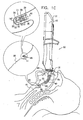
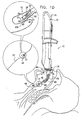
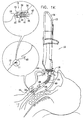
- FIGs. 1A to 1L are a series of simplified pictorial illustrations of a system and methodology for the intubation of a human in accordance with a preferred embodiment of the present invention.
- the general configuration of the mouth and trachea is generally the same for all humans except for differences in scale, such as between an infant, a child and an adult.
- a standard contour map 10 of the human mouth and trachea is employed.
- the scale of the map 10 may be further precisely adapted to the specific patient, preferably automatically.
- the scale of the map 10 is adapted to the specific patient semi-automatically.
- the operator can select the scale of the map 10, for example by selecting between a child and an adult. Thereafter the scale of the map 10 is automatically adapted to size of the specific patient as a part of the intubation process.
- the operator is enabled to designate one or more typical impediments such as: a tumor, a swelling, an infection and an injury. Selecting an impediment preferably creates a suitable variation of the general map 10.
- Fig. 1A shows the map 10 and the location therein where a tip sensor 11 of an intubator engages the mouth and trachea of the patient. It is a particular feature of the present invention that intubation is at least partially automatically effected by utilizing the contour map 10 to monitor the progress of tip sensor 11 and thus to navigate the intubator accordingly.
- an intubator assembly 12 suitable for the intubation of a human, is partially inserted into an oral cavity of a patient.
- the intubator assembly 12 preferably comprises a housing 14 in which is disposed a guide driver 15, a mouthpiece 16, a tube 18 inserted through the mouthpiece 16, a flexible guide 20 inserted through the tube 18, and tip sensor 11 mounted at the distal end of the guide 20.
- the mouthpiece 16 preferably comprises a rigid curved pipe 24 through which the tube 18 is inserted.
- the curved pipe 24 comprises a slit 49 on each side. Alternatively, the curved pipe 24 is eliminated.
- the components comprising the intubator assembly 12 may be disposable, for example, the tube 18 and the mouthpiece 16.
- the guide driver 15 is operative to move the guide 20 in and out of the housing 14, through the curved pipe 24 and through the tube 18.
- the guide driver 15 is also operative to selectably bend the distal end of the guide 20 clockwise and counterclockwise in the plane of the curvature of the curved pipe 24 in the sense of Fig. 1A .
- tip sensor 11 preferably comprises a tip 28 preferably integrally formed at one end of a short rod 30 having a magnet 32 on its other end.
- the rod 30 preferably extends through the center of a spring disk 34 and is firmly connected thereto.
- the spring disk 34 is preferably mounted on one end of a cylinder 36 whose other end is mounted on the distal end of the guide 20.
- the tip sensor 11 also comprises two Hall effect sensors, 38 and 40, which are mounted inside the cylinder 36 on a support 41 and in close proximity to the magnet 32.
- the Hall effect sensors 38 and 40 are preferably spaced in the plane of the curvature of the curved pipe 24.
- each Hall effect sensor has electrical terminals operative to provide electric current representing the distance of the magnet 32 therefrom.
- the output electric current of the Hall effect sensor 40 typically decreases and the output electric current of the Hall effect sensor 38 typically correspondingly increases.
- the tip sensor 11 enables electronic circuitry (not shown) to measure the amplitude and the direction of force exerted on the tip 28 in the plane of the Hall effect sensors 38 and 40 and to compute the orientation of a surface of a tissue against which the sensor tip 28 is depressed, relative to the axis of symmetry 42.
- sensors other than Hall effect sensors can be used to measure the direction and the amplitude of the force exerted on the tip 28, or otherwise to measure the proximity and the orientation of the adjacent surface.
- the guide driver 15 typically causes the guide 20 to extend in the direction of the trachea 44 and bends the guide 20 clockwise until the tip 28 engages a surface of the tongue 46. This engagement applies a force to tip 28, which causes the tip to rotate counterclockwise wherein the magnet 32 approaches the Hall effect sensor 38.
- Electronic circuitry (not shown) inside the housing 14, which measures the changes in the electrical outputs produced by the Hall effect sensors 38 and 40, indicates that the tip 28 is bent clockwise.
- the system of the present invention determines the location of the tip sensor 11 in the oral cavity and relative to the map 10. This location is employed in order to navigate the intubator correctly, as described hereinbelow.
- FIG. 1B illustrates a further step in the intubation in accordance with the present invention.
- Fig. 1B shows the guide 20 extended further and reaching an area between the base of the tongue 46 and the epiglottis 48 of the patient.
- the guide 20 extends further forward until the tip 28 touches the end of the trough beneath the epiglottis 48.
- the guide 20 bends counterclockwise and touches the bottom surface of the epiglottis 48. Then the guide 20 retracts a little, while preserving continuous tactile contact between the tip 28 with the bottom surface of the epiglottis 48.
- the guide 20 retracts further until the tip 28 of the tip sensor 11 reaches the tip 165 of the epiglottis 48 and then the tip 28 loses tactile contact with the surface of the tip 165 of the epiglottis 48.
- the guide 20 bends further counterclockwise, then extends forward and then bends clockwise until the tip 28 touches the upper surface of the epiglottis 48.
- the guide 20 extends forward, preserving continuous tactile contact with the epiglottis 48, until the tip 28 senses the first trough of the trachea 44.
- the guide 20 extends further forward until the tip 28 senses the second trough of the trachea 44.
- the guide 20 extends further forward until the tip 28 senses the trough of the third cartilage of the trachea 44. Then the guide 20 further extends, typically for adults by 5 centimeters, to ensure that the tube 16 reaches to the third cartilage.
- the guide driver 15 is pulled out with the guide 20 leaving the mouthpiece 16 and the tube 18 inside the patient's mouth and trachea 44.
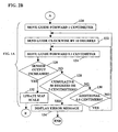
- FIGs. 2A to 2F are a flowchart of the process of the intubation of a human shown in Figs. 1A to 1K .
- Fig. 2A and 2B taken together, correspond to the step of the intubation process shown in Fig. 1A .
- step 100 of Fig. 2A the intubator assembly 12 is set to perform intubation.
- step 102 the intubator loads an intubation pattern map 10 from its memory.
- the intubator enables the operator to set the scale of the intubation pattern map to the corresponding size of the patient by selecting between an infant, a child and an adult.
- the intubator enables the operator to adapt the intubation pattern map 10 to a type of intubation impediment, preferably by selecting from a menu.
- the menu typically provides the operator with four optional impediments: an infection, a swelling, a tumor and an injury, and a fifth option not to select any impediment. It is appreciated that various types of impediments can be defined as is typical for a specific organ.
- steps 120, 122, 124, 126, 128 and 130 cause the guide 20 to extend in the direction of the throat and simultaneously bend clockwise until the tip sensor is depressed against the surface of the tongue or until extension and bending limits are reached.
- the bending limit is preferably 50 degrees and the extension limit is preferably 2 centimeters.
- the scale of the intubation pattern map 10 is preferably updated (step 132) to match the particular scale or size of the intubated patient. If at least one of the extension limit and the bending limit is reached an error message is displayed (step 134) and the intubation process is stopped.
- Fig. 2C corresponds to Figs. 1B and 1C .
- the guide driver 15 performs sequential steps 140, 142, 144 and 146 in a loop, extending (step 140) guide 20 further into the patient's throat and along the throat surface, following the intubation pattern map 10 and keeping the tip in contact with the surface (steps 144, 146).
- the intubator assumes (step 142) that the tip 28 has reached the end of the trough beneath the epiglottis 48.
- the point of engagement between the tip 28 and the body is designated in Fig. 1C by reference numeral 147.
- the scale of the intubation pattern map 10 is then preferably updated to match the patient's organ structure (step 148).
- Fig. 2D corresponds to Figs. 1D and 1E .
- the guide driver 15 performs steps 150, 152 and 154 in a loop, bending the distal end of the guide 20 counterclockwise until the tip 28 touches the epiglottis 48, or until a bending limit, preferably of 45 degrees is reached (step 154) and the intubation stops (step 156).
- the preferred point of engagement between the tip 28 and the surface of the epiglottis is designated in Fig. 1D by reference numeral 155.
- the guide driver 15 After sensing an engagement between the tip 28 and the surface of the epiglottis, the guide driver 15 performs steps 158, 160, 162, and 164 in a loop, retracting the guide 20 further (step 158), and increasing the bending of the guide 20 (step 164), until the tip of the guide reaches the tip of the epiglottis 48, designated in Fig. 1E by reference numeral 165.
- the tip 28 When the tip 28 reaches the tip of the epiglottis 48, the tip 28 is released and the output electric currents from both Hall effect sensors decrease to a minimum.
- the intubation pattern map 10 is updated (step 166) to match the patient's organ structure.
- Fig. 2E corresponds to Figs. 1E and 1F .
- the guide driver 15 causes the guide 20 to move above and around the tip of the epiglottis 48 by causing the guide 20 to bend counterclockwise, preferably by 45 degrees, then to move forward down the throat by 5 millimeters and then to bend clockwise, preferably by 10 degrees (Step 170).
- the guide driver 15 performs steps 172, 174 and 176 in a loop, bending and extending (step 174) until the tip 28 of the guide touches the upper surface of the epiglottis 48 or until an extension limit, preferably of 1 centimeter, or a bending limit, preferably of 50 degrees, is reached, and the intubation is stopped (step 178).
- a preferred point of engagement between the tip 28 and the epiglottis is designated in Fig. 1F by reference numeral 177.
- a "cartilage crest counter N" is first zeroed (step 180). Then the guide driver 15, performing steps 182 to 198 in a loop, causes the guide 20 to move the sensor tip 11 forward (step 182) along the surface of the trachea 44, preserving contact between the tip 28 and the surface of the trachea (steps 186 and 188) by increasing the bend (step 188) as needed. Each time a crest (189 in Figs.
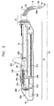
- the intubator assembly 12 preferably comprises the housing 14, the guide driver 15, the mouthpiece 16, the tube 18, the flexible guide 20 inserted inside the tube 18 and the tip sensor 11 mounted at the distal end of the guide 20.
- the mouthpiece comprises a curved pipe 24.
- the guide driver 15 comprises a first motor 210 that drives a gearbox 212 that rotates a threaded rod 214.
- a floating nut 216 is mounted on the threaded rod 214.
- the floating nut 216 is operative to move a carriage 218 along a bar 220 and thus to push or pull the guide 20.
- the stopper 222 moves with the carriage 218 along the bar 220 and pushes the tube 18 forward.
- a second motor 224 is connected to a disk 226 to which two guide angulation wires 228 are attached at first end thereof.
- the guide angulation wires 228 are threaded inside the guide 20 and their other ends are connected to the distal end of the guide just short of the tip sensor 11.
- the motor 224 rotates the disk 226 clockwise one of the wires 228 is pulled and the second wire is loosened.
- the wire that is pulled pulls and bends the distal end of the guide 20 counterclockwise in the sense of Fig. 3 .
- the motor 224 rotates counter-clockwise the second wire of the two wires 228 is pulled and the first wire is loosened.
- the wire that is pulled pulls and bends the distal end of the guide 20 clockwise in the sense of Fig. 3 .
- Electronic circuitry 229 is provided within the housing 14 and is preferably electrically connected to operating switches 230, a display 232, the motors 210 and 224 and to the Hall effect sensors 38 and 40 ( Fig. 1A ) in the tip sensor 11.
- the electronic circuitry 229 also comprises a microprocessor, operative to execute a program.
- the program is preferably adapted to control the switches 230, the display 232, motors 210 and 224 and the Hall effect sensors 38 and 40 and to insert and bend the guide inside a living organism, according to a predefined map until the tip of the guide reaches a destination point inside the living organism.
- the program is operative to cause the tip 28 of the guide 20 to follow a predefined internal contour of an organ of the living organism.
- the program is operative employ tactile sensing to measure the position of the tip of the guide relative to the surface organ of the living organism.
- microprocessor also includes inter alia a "microcontroller”.
- Electrical batteries are preferably provided within the housing 14 to supply electric power to the electronic circuitry, the tip sensor 11, the motors 210 and 224, the display 232 and all other elements of the present invention that consume electricity. It is appreciated that external sources of electricity can also be employed to provide power to the intubator assembly 12.
- Communication interface (not shown), preferably employing infra-red communication technology, is provided to enable communication with external data processing equipment.
- a balloon 234 is provided at the distal end of the tube 18 and a thin pipe (not shown) is inserted through the pipe 18 and is connected, through the side of the pipe, to the balloon.
- the thin pipe enables an operator to inflate the balloon when the distal end of the pipe 18 reaches the appropriate place in the trachea, thus securing the distal end of the pipe to the trachea.
- FIG. 4 is a simplified functional block diagram of a preferred embodiment of the guide driver 15 described hereinabove.
- the guide 20 is driven by two drivers.
- a longitudinal driver 240 preferably comprises a motor 210, the gear 212, the threaded rod 214, the floating nut 146 and the carriage 218 of Fig. 3 .
- a bending guide driver 242 preferably comprises the motor 224, the disk 226 and wires 228 ( Fig. 3 ).
- the longitudinal driver 240 and the bending guide driver 242 are controlled by two software driver modules.
- a longitudinal software driver module 244 controls the longitudinal driver 240 and comprises two functions: an extend function 246 and a retract function 248.
- a bending software driver 250 controls the bending guide driver 242 and comprises two functions: a bend counterclockwise function 252 and a bend clockwise function 254.
- the functions 246, 248, 252 and 254 are operated by a propagation control software module 256.
- the tip sensor 11 measures the proximity and orientation of an adjacent surface.
- the tip sensor 11 performs the proximity and orientation measurements by measuring the force applied to a tactile tip by a surface of an adjacent tissue.
- a tip sensor software driver module 260 operative to receive input signals from the tip sensor 11, provides two input functions: a counterclockwise tip rotation function 262 and a clockwise tip rotation function 264. The measurements of the tip positions as provided by the tip sensor software driver module 260 are collected and stored by a sensor log module 266.
- the map 10 is loaded into memory and serves as an updatable map 268.
- a comparator 270 compares the accumulated measurements from the tip sensor 11 with the updated reference map 268. The results of the comparisons are calculated by an update scale module 272 to provide a scaling factor that is applied to update the updated map 268. Consequently a navigation module 274 employs the updated map information to instruct the propagation control 256 to execute the next step of the insertion program.
- a measurement of the electric current drawn by at least one of the longitudinal guide drive and the bending guide drive can also serve as an input to the comparator 270 to evaluate the position of the tip sensor.
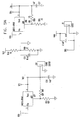
- Figs. 5A to 5H are, taken together, an electrical schematic of a preferred embodiment of the present invention useful for intubation of a human.
- microprocessor 278 which is preferably operative to operate a program to control the elements of the intubator assembly 12, such as the operating switches 230, the display 232, the motors 210 and 224 ( Fig. 3 ), and the Hall effect sensors 38 and 40 in the tip sensor 11 ( Fig. 1A ), and to perform the intubation process, such as the process shown and described hereinabove with reference to Figs. 2A to 2F .
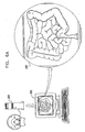
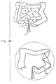
- FIGs. 6A to 6K are a series of simplified pictorial illustrations of ten typical steps in a process of employing a preferred embodiment of the present invention useful for insertion of an element into the intestine of a human.
- a map of the organ is prepared before the insertion process is activated.
- the required map is preferably prepared by employing an appropriate medical imaging system, such as an ultrasound scanner, an x-ray imager, a CAT scan system or a MRI system.
- the map can be a two dimensional map or a three-dimensional map as appropriate for the specific organ. Typically for the intestine system a three dimensional map is required.
- an inserter according to a preferred embodiment of the present invention for use in organs that are variable in three dimensions is similar to the intubator assembly 12, preferably with the following modifications:
- the guide 20 when the guide 20 performs longitudinal motion, such as insertion or retraction, the guide 20 also performs a small and relatively fast lateral motion.
- the combined longitudinal and lateral motions are useful for sensing the surface of the organ in three dimensions and hence to better determine the location of the tip sensor 11 in the organ and relative to the map 10.
- Figs. 6A to 6K Due to limitations of the graphical representation, a two-dimensional imaging and map is shown in Figs. 6A to 6K .
- a human organ is imaged, typically by a CAT scan system 280, and an image 282 of the internal structure of the organ is produced.
- the image 282 of the organ is used to create an insertion map 284.
- the image 282 is displayed on a computer screen (not shown) and a pointing device, such as a computer mouse or a light pen, is used to draw a preferred path 286 that the tip of the guide is to follow.
- the path is typically drawn by marking a contour of the organ, and optionally marking the guide bending points, as is shown and described with reference to Figs. 1A to 1K .
- a preferred path is created, such as path 286, not necessarily continuously following the contours of the organ.
- the map 10 or the path 286 is converted into a set of insertion steps as is shown and described hereinbelow with reference to Fig. 7 .
- a table 290 is provided for storage in a computer memory and for processing by a computer processor.
- the table 290 contains rows 292, wherein each row 292, preferably comprises an instruction to perform one step in the process of insertion of a medical insertion device into a living organism such as shown and described with reference to Figs. 6C to 6K .
- each row 292 contains the expected values or the maximal values for the extension of an insertion guide such as guide 20, the bending of the insertion guide and the electrical outputs from the Hall effect sensors 38 and 40 ( Fig. 1A ).
- the row 292 contains five sets of values:
- Fig. 6B can be employed to prepare a table of instructions, such as table 290 of Fig. 7 .
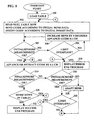
- FIG. 8 is a flowchart illustrating a preferred implementation of the present invention, operative for a process of insertion of an element into the intestine of a human as shown in Figs. 6A to 6K .
- the flowchart of Fig. 8 is a preferred embodiment of a program, operative to be executed by a processor, such as microprocessor 278 of Fig. 5A , comprised in a preferred embodiment of the present invention, for insertion of an element into a living organism, preferably by employing a table 290 shown and described with reference to Fig. 7 .
- the preferred flowchart shown in Fig. 8 starts by loading the table (step 300) such as the map shown in Fig. 7 .
- the program then reads a first row 292 from the map (step 302) and causes the distal end of the guide 20 to bend according to the initial bending values 294. Then the program causes the guide 20 to extend or retract according to the initial insertion distance 295 of the first row in the map.
- the program continues to bend and insert the guide 20 until output values of the sensors match the expected initial sensor measurement 296 of the row (steps 304, 306 and 308), or until a limit is surpassed, an error message is displayed and the program is stopped (step 310).
- the initial values of the sensors are measured and then the program continues to extend or retract the guide 20 (step 312) until the sensors produce the final sensors measurements 298 values (step 314), while keeping in contact with the surface (steps 316 and 318) or until at least one of predefined limits is surpassed (step 320) where the program is stopped (step 310). If the final sensor measurements 298 values are measured the program proceeds to step 320 and loops through steps 302 and 320 until all the rows 292 of the table are processed. Then the program displays an insertion success message on the display 232 and halts (step 322).
- the guide is bent, preferably by up to 45 degrees, to the left in the plane of Fig. 6C and, while preserving contact with the left side of the intestine, is extended up to 5 centimeters or until the sensor tip engages the internal surface of the intestine head on at a point in the map 284 designated by reference numeral 330.
- the guide is bent by up to 45 degrees to the right in the plane of Fig. 6D and, while preserving contact with the left side of the intestine, is extended up to 2.5 centimeters or until the sensor tip does not sense the internal surface of the intestine at a point in the map 284 designated by reference numeral 332.
- the guide is bent by up to 110 degrees to the left in the plane of Fig. 6E and, while preserving contact with the left side of the intestine, is extended by 1 centimeter to a point in the map 284 designated by reference numeral 334.
- the guide is bent by up to 45 degrees to the right in the plane of Fig. 6F and is extended by 6 centimeter to a point in the map 284 designated by reference numeral 336.
- the guide is bent by up to 20 degrees to the right in the plane of Fig. 5G and, while preserving contact with the right side of the intestine, is extended by 4 centimeters to a point in the map 284 designated by reference numeral 338.
- the guide is bent by up to -60 degrees to the left in the plane of Fig. 6H and is extended by up to 3 centimeters or until the sensor tip engages the internal surface of the intestine head on at a point in the map 284 designated by reference numeral 340.
- the guide is bent by up to 45 degrees to the right in the plane of Fig. 6I and is extended by up to 1 centimeter or until the sensor tip engages the internal surface of the intestine with its right side in a point in the map 284 designated by reference numeral 342.
- the guide is extended by up to 1 centimeters or until the sensor tip engages the internal surface of the intestine with its left side at a point in the map 284 designated by reference numeral 344,
- the guide is bent by up to 45 degrees to the right in the plane of Fig. 6K and is extended by up to 1 centimeter or until the sensor tip engages the internal surface of the intestine head on at a point in the map 284 designated by reference numeral 346.
- the system and the method are operative for automatic operation.
- the present invention can be operated manually, by providing to the operator the information collected by the sensor log 266 from the tip sensor 11 and enabling the operator to control manually the guide 20.
- the guide 20 may be inserted automatically and a medical device, such as the tube 18 may be inserted manually.
- a log of the process of insertion of an insertable element into a living organism such as a human body is preferably stored in an internal memory of the present invention and that this log can be transmitted to a host computer. It is appreciated that the host computer can aggregate insertion process logs and thereby continuously improve relevant insertion pattern maps such as the standard contour map 10. Thereafter, from time to time or before starting an insertion process, the present invention is capable of loading an updated map such as standard contour map 10.
- the accumulated logs of processes of insertions can be employed to improve the algorithm for processing the maps, such as the algorithms shown and described with reference to Figs. 2A - 2F and Fig. 8 .
- the improved algorithm can be transmitted to the present invention as necessary.
- Appendices 1 to 3 are software listings of the following computer files:
- the method for providing the software functionality of the microprocessor 278, in accordance with a preferred embodiment of the present invention includes the following steps:
- the software components of the present invention may, if desired, be implemented in ROM (read-only memory) form.
- the software components may, generally, be implemented in hardware, if desired, using conventional techniques.
- Appendices 1 through 3 are as follows:
Landscapes
- Health & Medical Sciences (AREA)
- Life Sciences & Earth Sciences (AREA)
- Engineering & Computer Science (AREA)
- Pulmonology (AREA)
- Animal Behavior & Ethology (AREA)
- Veterinary Medicine (AREA)
- Public Health (AREA)
- Biomedical Technology (AREA)
- Heart & Thoracic Surgery (AREA)
- General Health & Medical Sciences (AREA)
- Otolaryngology (AREA)
- Emergency Medicine (AREA)
- Anesthesiology (AREA)
- Hematology (AREA)
- Surgery (AREA)
- Molecular Biology (AREA)
- Medical Informatics (AREA)
- Pathology (AREA)
- Biophysics (AREA)
- Physics & Mathematics (AREA)
- Human Computer Interaction (AREA)
- Endoscopes (AREA)
- Sampling And Sample Adjustment (AREA)
- Fluid-Driven Valves (AREA)
- Surgical Instruments (AREA)
- Paper (AREA)
- Jet Pumps And Other Pumps (AREA)
- Solid-Sorbent Or Filter-Aiding Compositions (AREA)
- External Artificial Organs (AREA)
- Infusion, Injection, And Reservoir Apparatuses (AREA)
- Measuring And Recording Apparatus For Diagnosis (AREA)
- Massaging Devices (AREA)
Claims (13)
- Automatisch betreibbare medizinische Einführungsvorrichtung (12), die aufweist:ein einführbares bzw. einsetzbares Element (16, 18, 20), welches für ein Einführen bzw. Einsetzen innerhalb eines lebenden Organismus in vivo ausgestaltet ist,ein der Oberfläche folgendes Element (11), welches physisch mit dem einführbaren Element (16, 18, 20) verbunden ist und so angeordnet ist, daß es einer physischen Oberfläche (44, 46, 48) innerhalb des lebenden Organismus in vivo folgt,ein Antriebs-Teilsystem (16), welches so betreibbar ist, daß es das einführbare Element (16, 18, 20) wenigstens teilweise automatisch entlang der physischen Oberfläche (44, 46, 48) führt, undein Navigations-Teilsystem (229), welches so betreibbar ist, daß es das Antriebs-Teilsystem (15) wenigstens teilweise auf Basis einer erkannten Position des der Oberfläche folgenden Elements (11) entlang eines Vergleichspfades (10), der in dem Navigations-Teilsystem gespeichert ist, steuert,dadurch gekennzeichnet, daß
das der Oberfläche folgende Element (11) ein taktiles Abtastelement (28) umfaßt,
wobei der Vergleichspfad (10) eine vordefinierte innere Kontur eines Organs des lebenden Organismus umfaßt, und
das Navigations-Teilsystem (229) so betreibbar ist, daß es das taktile Abtastelement (28) verwendet, um zu bewirken, daß das der Oberfläche folgende Element (11) dem Vergleichspfad (10) folgt. - Automatisch betreibbare medizinische Einführungsvorrichtung nach Anspruch 1, wobei das Antriebs-Teilsystem (15) so betreibbar ist, daß es das einführbare Element (16, 18, 20) völlig automatisch entlang der physischen Oberfläche (44, 46, 48) führt.
- Automatisch betreibbare medizinische Einführungsvorrichtung nach Anspruch 1, wobei das Antriebs-Teilsystem (15) so betreibbar ist, daß es das einführbare Element (16, 18, 20) automatisch und auswählbar entlang der physischen Oberfläche (44, 46, 48) führt.
- Automatisch betreibbare medizinische Einführungsvorrichtung nach einem der vorangegangenen Ansprüche, welche auch einen Vergleichspfadgenerator umfaßt, der so betreibbar ist, daß er wenigstens einen Teil bzw. Abschnitt des lebenden Organismus abbildet und den Vergleichspfad (286) wenigstens teilweise auf Basis einer dadurch erzeugten Abbildung (282) erzeugt.
- Automatisch betreibbare medizinische Einführungsvorrichtung nach Anspruch 4, wobei der Vergleichspfad (286) eine standardmäßige Konturabbildung (10, 284) eines Teils der menschlichen Anatomie umfaßt.
- Automatisch betreibbare medizinische Einführungsvorrichtung nach Anspruch 5, wobei die standardmäßige Konturabbildung (10, 284) genau an einen spezifischen Patienten angepaßt ist.
- Automatisch betreibbare medizinische Einführungsvorrichtung nach einem der vorangegangenen Ansprüche, wobei das einführbare Element (16, 18, 20) ein Gehäuse (14), in welchem das Antriebs-Teilsystem (15) angeordnet ist, ein Mundstück (16), einen durch das Mundstück eingesetzten Schlauch (18) und eine durch den Schlauch eingesetzte flexible Führung (20) umfaßt, wobei das der Oberfläche folgende Element (11) an einem vorderen Ende der Führung (20) befestigt ist.
- Automatisch betreibbare medizinische Einführungsvorrichtung nach Anspruch 7, wobei das Mundstück (16) ein gebogenes bzw. gekrümmtes Rohr (24) umfaßt, durch welches der Schlauch (18) eingesetzt ist.
- Automatisch betreibbare medizinische Einführungsvorrichtung nach Anspruch 8, wobei das Antriebs-Teilsystem (15) so betreibbar ist, daß es die Führung (20) durch das gebogene Rohr (24) und durch den Schlauch (18) in das Gehäuse (14) hinein und aus diesem hinaus bewegt.
- Automatisch betreibbare medizinische Einführungsvorrichtung nach einem der vorangegangenen Ansprüche, wobei das der Oberfläche folgende Element (11) einen Spitzensensor (11) aufweist, der eine Spitze (28) hat, die an einem Ende einer kurzen Stange (30) einstückig ausgebildet ist, die an ihrem anderen Ende einen Magneten (32) aufweist, wobei sich die Stange (30) durch das Zentrum einer Federscheibe (34) erstreckt und fest mit dieser verbunden ist, wobei die Federscheibe (34) an einem Ende eines Zylinders (36) befestigt ist, dessen anderes Ende an einem vorderen Ende des einführbaren Elements (16, 18, 20) befestigt ist.
- Automatisch betreibbare medizinische Einführungsvorrichtung nach Anspruch 10, wobei der Spitzensensor (11) auch zwei Hall-Effekt-Sensoren (38, 40) umfaßt, die innerhalb des Zylinders (36) auf einem Träger (41) montiert sind und sehr nahe bei dem Magneten (32) liegen, wobei die Hall-Effekt-Sensoren (38, 40) in der Krümmungsebene des gebogenen bzw. gekrümmten Rohrs (24) beabstandet angeordnet sind, wobei jeder Hall-Effekt-Sensor (38, 40) elektrische Anschlüsse hat, die so betreibbar sind, daß sie einen elektrischen Strom bereitstellen, der den Abstand des Magneten (32) hiervon repräsentiert, wobei der Spitzensensor (11) so betreibbar ist, daß, wenn entlang einer Symmetrieachse (42) des Zylinders (36) eine Kraft auf die Spitze (28) ausgeübt wird, die Spitze (28) gegen die Federscheibe (34) gedrückt wird, wodurch der Magnet (32) dazu gebracht wird, sich den Hall-Effekt-Sensoren (38, 40) zu nähern, und wenn in der Ebene der Hall-Effekt-Sensoren (38, 40) seitlich eine Kraft auf die Spitze (28) ausgeübt wird, sich die Spitze (28) um eine Position dreht, an welcher die Stange (30) mit der Federscheibe (34) in Eingriff ist, wodurch der Magnet (32) veranlaßt wird, sich von einem der Hall-Effekt-Sensoren (38, 40) weg und näher zu dem anderen der Hall-Effekt-Sensoren (38, 40) hin zu drehen.
- Automatisch betreibbare medizinische Einführungsvorrichtung nach Anspruch 11, wobei das Navigations-Teilsystem (229) so betreibbar ist, daß es die Veränderungen der durch die Hall-Effekt-Sensoren (38, 40) erzeugten elektrischen Ausgänge mißt, die die Richtung anzeigen, in welcher die Spitze (28) gebogen ist.
- Automatisch betreibbare medizinische Einführungsvorrichtung nach Anspruch 12, wobei das Navigations-Teilsystem (229) so betreibbar ist, daß es die Position der Spitze (28) und die Vorgeschichte von Spitzenpositionen abtastet und die Position der Spitze (28) in dem lebenden Organismus und relativ zu dem Vergleichspfad (10) bestimmt.
Applications Claiming Priority (3)
| Application Number | Priority Date | Filing Date | Title |
|---|---|---|---|
| IL140136A IL140136A (en) | 2000-12-06 | 2000-12-06 | Apparatus for self-guided intubation |
| IL14013600 | 2000-12-06 | ||
| PCT/IL2001/001121 WO2002045768A2 (en) | 2000-12-06 | 2001-12-05 | Apparatus for self-guided intubation |
Publications (3)
| Publication Number | Publication Date |
|---|---|
| EP1349522A2 EP1349522A2 (de) | 2003-10-08 |
| EP1349522A4 EP1349522A4 (de) | 2006-05-17 |
| EP1349522B1 true EP1349522B1 (de) | 2008-12-03 |
Family
ID=11074892
Family Applications (1)
| Application Number | Title | Priority Date | Filing Date |
|---|---|---|---|
| EP01999397A Expired - Lifetime EP1349522B1 (de) | 2000-12-06 | 2001-12-05 | Apparat für die selbstgeführte intubation |
Country Status (10)
| Country | Link |
|---|---|
| US (2) | US7089928B2 (de) |
| EP (1) | EP1349522B1 (de) |
| JP (1) | JP2004522480A (de) |
| AT (1) | ATE415854T1 (de) |
| AU (2) | AU2245002A (de) |
| CA (1) | CA2430834C (de) |
| DE (1) | DE60136847D1 (de) |
| IL (1) | IL140136A (de) |
| WO (1) | WO2002045768A2 (de) |
| ZA (1) | ZA200304238B (de) |
Families Citing this family (40)
| Publication number | Priority date | Publication date | Assignee | Title |
|---|---|---|---|---|
| US20060040904A1 (en) * | 2004-08-17 | 2006-02-23 | Ahmed Salah U | Vaginal cream compositions, kits thereof and methods of using thereof |
| ES2425388T3 (es) | 2005-05-06 | 2013-10-15 | Vasonova, Inc. | Aparato para el guiado y posicionamiento de un dispositivo endovascular |
| US8116886B2 (en) * | 2005-10-14 | 2012-02-14 | The Trustees Of Columbia University In The City Of New York | Electrode arrays and systems for inserting same |
| US8746239B2 (en) * | 2006-07-19 | 2014-06-10 | Douglas K. Yoshida | Extendable lighted intubation stylet |
| US20080216840A1 (en) * | 2007-03-06 | 2008-09-11 | Searete Llc, A Limited Liability Corporation Of The State Of Delaware | Imaging via the airway |
| US8175689B2 (en) * | 2007-03-19 | 2012-05-08 | Nicholas Hunter-Jones | Skin elasticity measurement |
| US8419634B2 (en) | 2007-06-12 | 2013-04-16 | University Hospitals Of Cleveland | Apparatus and method for airway management |
| US8460184B2 (en) * | 2009-12-11 | 2013-06-11 | University Hospitals Of Cleveland | Airway management |
| US20080216826A1 (en) * | 2007-08-07 | 2008-09-11 | Searete Llc, A Limited Liability Corporation Of The State Of Delaware | Airway imaging system |
| US20090024018A1 (en) * | 2007-08-07 | 2009-01-22 | Searete Llc, A Limited Liability Corporation Of The State Of Delaware | Anatomical imaging system |
| US8166967B2 (en) * | 2007-08-15 | 2012-05-01 | Chunyuan Qiu | Systems and methods for intubation |
| JP4902620B2 (ja) * | 2008-10-21 | 2012-03-21 | オリンパスメディカルシステムズ株式会社 | カプセル誘導システム |
| US8423182B2 (en) | 2009-03-09 | 2013-04-16 | Intuitive Surgical Operations, Inc. | Adaptable integrated energy control system for electrosurgical tools in robotic surgical systems |
| WO2010129327A1 (en) * | 2009-05-05 | 2010-11-11 | Tufts Medical Center | Tracheal intubation device |
| DE102009038588A1 (de) * | 2009-08-26 | 2011-03-24 | Degudent Gmbh | Verfahren zur Ermittlung eines Gesamtdatensatzes eines zu messenden Objektes |
| WO2011040111A1 (ja) * | 2009-09-30 | 2011-04-07 | オリンパスメディカルシステムズ株式会社 | 内視鏡装置 |
| EP2493554B1 (de) * | 2009-10-30 | 2018-09-12 | Advanced Bionics, LLC | Steuerbarer mandrin |
| WO2011053766A1 (en) * | 2009-10-30 | 2011-05-05 | Advanced Bionics, Llc | Steerable stylet |
| US20130035548A1 (en) * | 2010-03-22 | 2013-02-07 | Tufts Medical Center, Inc. | Fiber optic intubating device |
| US8894569B2 (en) | 2010-04-21 | 2014-11-25 | Chunyuan Qiu | Intubation systems and methods based on airway pattern identification |
| US9795753B2 (en) | 2012-03-07 | 2017-10-24 | Chunyuan Qiu | Intubation delivery systems and methods |
| US9750912B2 (en) | 2011-05-04 | 2017-09-05 | The Regents Of The University Of Michigan | Intubation device |
| DE102011085047A1 (de) | 2011-10-21 | 2013-04-25 | Carl Zeiss Meditec Ag | Erzeugung von Schnitten in einem transparenten Material mittels optischer Strahlung |
| WO2013090619A1 (en) | 2011-12-15 | 2013-06-20 | The Board Of Trustees Of The Leland Stanford Junior University | Devices and methods for preventing tracheal aspiration |
| KR102335797B1 (ko) | 2012-09-17 | 2021-12-07 | 인튜어티브 서지컬 오퍼레이션즈 인코포레이티드 | 원격조작 수술 기구 기능들에 입력 장치들을 할당하는 방법 및 시스템 |
| CN115486942A (zh) * | 2012-11-02 | 2022-12-20 | 直观外科手术操作公司 | 流传输连接器和系统、流消歧以及用于映射流供应路径的系统和方法 |
| US10631939B2 (en) | 2012-11-02 | 2020-04-28 | Intuitive Surgical Operations, Inc. | Systems and methods for mapping flux supply paths |
| US10864048B2 (en) * | 2012-11-02 | 2020-12-15 | Intuitive Surgical Operations, Inc. | Flux disambiguation for teleoperated surgical systems |
| WO2015069804A1 (en) | 2013-11-05 | 2015-05-14 | Ciel Medical, Inc. | Devices and methods for airway measurement |
| TWI564041B (zh) * | 2014-08-28 | 2017-01-01 | Apex Medical Corp | A breathing gas supply system and a control method thereof, and a computer program product for executing the method |
| US10610655B2 (en) * | 2014-10-20 | 2020-04-07 | Ohio State Innovation Foundation | Intubation with audiovibratory guidance |
| EP3551056B1 (de) * | 2017-02-06 | 2022-06-22 | St. Jude Medical International Holding S.à r.l. | Herzkatheter mit verformbarem körper |
| CN107080888A (zh) * | 2017-05-15 | 2017-08-22 | 刘�英 | 一种能够辅助气管插管的口腔开口器 |
| WO2018235255A1 (ja) * | 2017-06-23 | 2018-12-27 | オリンパス株式会社 | 医療システムとその作動方法 |
| CN109325232A (zh) * | 2018-09-25 | 2019-02-12 | 北京明朝万达科技股份有限公司 | 一种基于lda的用户行为异常分析方法、系统及存储介质 |
| US20200375665A1 (en) * | 2019-05-31 | 2020-12-03 | Canon U.S.A., Inc. | Medical continuum robot and methods thereof |
| CN110368241A (zh) * | 2019-08-20 | 2019-10-25 | 蔡元雪 | 一种骨科护理用便于换药固定设备 |
| US12090273B1 (en) * | 2019-12-13 | 2024-09-17 | Someone is Me | System and method for automated intubation |
| AU2021275774A1 (en) | 2020-05-19 | 2022-12-22 | Spiro Robotics, Inc. | Robotic-assisted navigation and control for airway management procedures, assemblies and systems |
| WO2023201210A1 (en) * | 2022-04-10 | 2023-10-19 | Spiro Robotics, Inc. | Disposable controls, re-usable devices, and their methods of use |
Family Cites Families (89)
| Publication number | Priority date | Publication date | Assignee | Title |
|---|---|---|---|---|
| US4651746A (en) | 1984-05-08 | 1987-03-24 | Wall William H | Oral airway and endotrachial monitor |
| US4672960A (en) * | 1984-08-15 | 1987-06-16 | Renbec International Corporation | Automatic intubation device for guiding endotracheal tube into trachea |
| US4691701A (en) | 1986-07-28 | 1987-09-08 | Tudor Williams R | Carbon dioxide detector |
| US4728499A (en) | 1986-08-13 | 1988-03-01 | Fehder Carl G | Carbon dioxide indicator device |
| US4827925A (en) | 1986-10-20 | 1989-05-09 | Vilasi Joseph A | Cuffless adjustable endotracheal tube |
| US5203320A (en) | 1987-03-24 | 1993-04-20 | Augustine Medical, Inc. | Tracheal intubation guide |
| US4790327A (en) | 1987-07-27 | 1988-12-13 | George Despotis | Endotracheal intubation device |
| US5172225A (en) | 1987-11-25 | 1992-12-15 | Olympus Optical Co., Ltd. | Endoscope system |
| GB2225188B (en) | 1988-11-16 | 1993-05-12 | Olympus Optical Co | Methods of detecting endoscope insertion direction |
| US5018509A (en) | 1989-02-21 | 1991-05-28 | Olympus Optical Co., Ltd. | Endoscope insertion controlling apparatus |
| US5681260A (en) * | 1989-09-22 | 1997-10-28 | Olympus Optical Co., Ltd. | Guiding apparatus for guiding an insertable body within an inspected object |
| DE4102196C2 (de) | 1990-01-26 | 2002-08-01 | Olympus Optical Co | Abbildungsvorrichtung zum Nachführen eines Objektes |
| US5235970A (en) | 1990-03-26 | 1993-08-17 | Augustine Medical, Inc. | Tracheal intubation with a stylet guide |
| US5109830A (en) | 1990-04-10 | 1992-05-05 | Candela Laser Corporation | Apparatus for navigation of body cavities |
| US5188111A (en) * | 1991-01-18 | 1993-02-23 | Catheter Research, Inc. | Device for seeking an area of interest within a body |
| US5445625A (en) | 1991-01-23 | 1995-08-29 | Voda; Jan | Angioplasty guide catheter |
| US5184603A (en) | 1991-02-15 | 1993-02-09 | Stone J Gilbert | Automatic intubating laryngoscope |
| DE4105326A1 (de) | 1991-02-21 | 1992-09-03 | Wolf Gmbh Richard | Endoskop mit proximal ankuppelbarer kamera |
| US5257636A (en) | 1991-04-02 | 1993-11-02 | Steven J. White | Apparatus for determining position of an endothracheal tube |
| US5347987A (en) | 1991-04-08 | 1994-09-20 | Feldstein David A | Self-centering endoscope system |
| US5469840A (en) * | 1991-12-10 | 1995-11-28 | Olympus Optical, Ltd. | Electromotive warping type endoscope with velocity control |
| IT1252817B (it) | 1991-12-13 | 1995-06-28 | Elio Valenti | Laringoscopio basculante a spatula ricurva motorizzata, particolarmente per praticare l' intubazione di pazienti sotto anestesia o rianimazione |
| US6757557B1 (en) * | 1992-08-14 | 2004-06-29 | British Telecommunications | Position location system |
| JP3268853B2 (ja) * | 1992-10-23 | 2002-03-25 | オリンパス光学工業株式会社 | 生体内挿入具誘導装置 |
| US5400771A (en) * | 1993-01-21 | 1995-03-28 | Pirak; Leon | Endotracheal intubation assembly and related method |
| US5331967A (en) | 1993-02-05 | 1994-07-26 | Playa De Los Vivos S.A. | Tracheal intubation monitoring apparatus and method |
| WO1996011624A2 (en) | 1994-10-07 | 1996-04-25 | St. Louis University | Surgical navigation systems including reference and localization frames |
| US5282472A (en) | 1993-05-11 | 1994-02-01 | Companion John A | System and process for the detection, evaluation and treatment of prostate and urinary problems |
| US5657759A (en) | 1993-05-13 | 1997-08-19 | Synectics Medical, Incorporated | Measurement of gastric emptying and gastrointestinal output |
| US5445161A (en) | 1993-10-08 | 1995-08-29 | Huang; K. C. | Apparatus and method for capnography-assisted endotracheal intubation |
| US5885248A (en) | 1994-02-22 | 1999-03-23 | Wolf Tory Medical, Inc. | Intubation detection system with transducer based indicator |
| US5582167A (en) * | 1994-03-02 | 1996-12-10 | Thomas Jefferson University | Methods and apparatus for reducing tracheal infection using subglottic irrigation, drainage and servoregulation of endotracheal tube cuff pressure |
| US5571114A (en) | 1994-07-13 | 1996-11-05 | Devanaboyina; Udaya-Sankar | Mechanism to advance or withdraw objects in lumens or cavities of mammals |
| NO300407B1 (no) * | 1994-08-30 | 1997-05-26 | Vingmed Sound As | Apparat for endoskop- eller gastroskopundersökelse av pasienter |
| US5492131A (en) * | 1994-09-06 | 1996-02-20 | Guided Medical Systems, Inc. | Servo-catheter |
| US5560351A (en) * | 1994-10-07 | 1996-10-01 | University Of Florida | Transtracheal energy application and sensing system for intubation: method and apparatus |
| US5558082A (en) | 1995-01-09 | 1996-09-24 | Spencer; Robert F. | Method of intubating a patient and introducer for use with such method |
| US5971997A (en) | 1995-02-03 | 1999-10-26 | Radionics, Inc. | Intraoperative recalibration apparatus for stereotactic navigators |
| US5882206A (en) * | 1995-03-29 | 1999-03-16 | Gillio; Robert G. | Virtual surgery system |
| US5592939A (en) | 1995-06-14 | 1997-01-14 | Martinelli; Michael A. | Method and system for navigating a catheter probe |
| US5824005A (en) * | 1995-08-22 | 1998-10-20 | Board Of Regents, The University Of Texas System | Maneuverable electrophysiology catheter for percutaneous or intraoperative ablation of cardiac arrhythmias |
| US6196225B1 (en) | 1995-10-23 | 2001-03-06 | Dean O. Allgeyer | Endotracheal tube for use during fiberoptic assisted intubation and with other intubating stylets |
| US5704987A (en) | 1996-01-19 | 1998-01-06 | International Business Machines Corporation | Process for removing residue from a semiconductor wafer after chemical-mechanical polishing |
| IL117250A (en) | 1996-02-23 | 2000-06-01 | Arco Medic Ltd | Laryngoscope |
| US6568388B2 (en) * | 1996-02-26 | 2003-05-27 | Evergreen Medical Incorporated | Method and apparatus for ventilation / oxygenation during guided insertion of an endotracheal tube |
| US5720275A (en) | 1996-03-26 | 1998-02-24 | The Research Foundation Of State Univ. Of New York | Tracheal guide |
| US6167145A (en) | 1996-03-29 | 2000-12-26 | Surgical Navigation Technologies, Inc. | Bone navigation system |
| US5762613A (en) | 1996-05-07 | 1998-06-09 | Spectrascience, Inc. | Optical biopsy forceps |
| EP0904127B1 (de) * | 1996-05-17 | 2005-02-23 | Biosense Webster, Inc. | Selbstausrichtender katheter |
| US6152909A (en) | 1996-05-20 | 2000-11-28 | Percusurge, Inc. | Aspiration system and method |
| DE19630367A1 (de) | 1996-07-28 | 1998-01-29 | Uwe Emig | Bindungsträgerplatte für einen Ski |
| US5993424A (en) | 1996-08-05 | 1999-11-30 | Cordis Corporation | Guidewire having a distal tip that can change its shape within a vessel |
| US5971767A (en) * | 1996-09-16 | 1999-10-26 | The Research Foundation Of State University Of New York | System and method for performing a three-dimensional virtual examination |
| US5951571A (en) | 1996-09-19 | 1999-09-14 | Surgical Navigation Specialist Inc. | Method and apparatus for correlating a body with an image of the body |
| US6016439A (en) * | 1996-10-15 | 2000-01-18 | Biosense, Inc. | Method and apparatus for synthetic viewpoint imaging |
| US5810008A (en) | 1996-12-03 | 1998-09-22 | Isg Technologies Inc. | Apparatus and method for visualizing ultrasonic images |
| US5951461A (en) * | 1996-12-20 | 1999-09-14 | Nyo; Tin | Image-guided laryngoscope for tracheal intubation |
| US5964732A (en) * | 1997-02-07 | 1999-10-12 | Abbeymoor Medical, Inc. | Urethral apparatus with position indicator and methods of use thereof |
| US6146402A (en) | 1997-06-09 | 2000-11-14 | Munoz; Cayetano S. | Endotracheal tube guide introducer and method of intubation |
| US5954636A (en) * | 1997-07-15 | 1999-09-21 | Schwartz; Roy E. | Pediatric endotracheal tube with bronchial blocker and method for selectively blocking respiratory airflow to a pediatric patient's lung |
| US6079409A (en) | 1997-07-25 | 2000-06-27 | Brain; Archibald Ian Jeremy | Intubating laryngeal mask |
| US6015414A (en) * | 1997-08-29 | 2000-01-18 | Stereotaxis, Inc. | Method and apparatus for magnetically controlling motion direction of a mechanically pushed catheter |
| US6211904B1 (en) | 1997-09-11 | 2001-04-03 | Edwin L. Adair | Surgical devices incorporating reduced area imaging devices |
| US6096050A (en) | 1997-09-19 | 2000-08-01 | Surgical Navigation Specialist Inc. | Method and apparatus for correlating a body with an image of the body |
| US6226548B1 (en) | 1997-09-24 | 2001-05-01 | Surgical Navigation Technologies, Inc. | Percutaneous registration apparatus and method for use in computer-assisted surgical navigation |
| US6142144A (en) | 1997-12-01 | 2000-11-07 | Pacey; John A. | Intubation instrument |
| AUPP123698A0 (en) | 1998-01-07 | 1998-01-29 | Ayre, Peter | Self propelling endoscope |
| US5976072A (en) | 1998-01-29 | 1999-11-02 | Johns Hopkins University | Copa method for fiberoptic endotracheal intubation |
| US6053166A (en) | 1998-02-09 | 2000-04-25 | Gomez; Richard J. | Intubating assembly |
| EP1057161B1 (de) * | 1998-02-23 | 2002-05-02 | Algotec Systems Ltd. | System und methode zur automatischen wegplanung |
| US6173199B1 (en) | 1998-05-05 | 2001-01-09 | Syncro Medical Innovations, Inc. | Method and apparatus for intubation of a patient |
| US6096004A (en) | 1998-07-10 | 2000-08-01 | Mitsubishi Electric Information Technology Center America, Inc. (Ita) | Master/slave system for the manipulation of tubular medical tools |
| US6090040A (en) | 1998-09-10 | 2000-07-18 | Metro; R. J. | Periscope and retracting laryngoscope for intubation |
| US6248112B1 (en) | 1998-09-30 | 2001-06-19 | C. R. Bard, Inc. | Implant delivery system |
| US6398755B1 (en) * | 1998-10-06 | 2002-06-04 | Scimed Life Systems, Inc. | Driveable catheter system |
| US6164277A (en) | 1998-12-08 | 2000-12-26 | Merideth; John H. | Audio guided intubation stylet |
| US6190382B1 (en) | 1998-12-14 | 2001-02-20 | Medwaves, Inc. | Radio-frequency based catheter system for ablation of body tissues |
| US6202646B1 (en) | 1998-12-23 | 2001-03-20 | Para Products Incorporated | Detection device for verifying the proper intubation of an endotracheal tube |
| US6135948A (en) | 1999-01-25 | 2000-10-24 | Lee; Han Shik | Convertible laryngoscope |
| US6190395B1 (en) | 1999-04-22 | 2001-02-20 | Surgical Navigation Technologies, Inc. | Image guided universal instrument adapter and method for use with computer-assisted image guided surgery |
| ES2242622T3 (es) * | 1999-07-30 | 2005-11-16 | Boston Scientific Limited | Conexion de propulsion rotacional y de traslacion para conjunto de cateter. |
| US6189533B1 (en) | 1999-08-04 | 2001-02-20 | James S. Simon | Endotracheal intubation device |
| US6315739B1 (en) * | 1999-09-27 | 2001-11-13 | Instrumentarium Corporation | Apparatus and method for measuring the intratracheal pressure of an intubated patient |
| US6235038B1 (en) | 1999-10-28 | 2001-05-22 | Medtronic Surgical Navigation Technologies | System for translation of electromagnetic and optical localization systems |
| DE10000937B4 (de) * | 2000-01-12 | 2006-02-23 | Brainlab Ag | Intraoperative Navigationsaktualisierung |
| EP1174076A3 (de) | 2000-07-18 | 2002-10-16 | BIOTRONIK Mess- und Therapiegeräte GmbH & Co Ingenieurbüro Berlin | Vorrichtung zur automatischen Durchführung von diagnostischen und/oder therapeutischen Aktionen in Körperhöhlungen |
| US6609521B1 (en) * | 2001-04-09 | 2003-08-26 | Regents Of The University Of Minnesota | Endotracheal tube |
| US6877512B2 (en) * | 2001-09-05 | 2005-04-12 | The Regents Of The University Of California | Airway device |
| US20070208252A1 (en) * | 2004-04-21 | 2007-09-06 | Acclarent, Inc. | Systems and methods for performing image guided procedures within the ear, nose, throat and paranasal sinuses |
-
2000
- 2000-12-06 IL IL140136A patent/IL140136A/en not_active IP Right Cessation
-
2001
- 2001-12-05 WO PCT/IL2001/001121 patent/WO2002045768A2/en not_active Ceased
- 2001-12-05 CA CA2430834A patent/CA2430834C/en not_active Expired - Fee Related
- 2001-12-05 AU AU2245002A patent/AU2245002A/xx active Pending
- 2001-12-05 JP JP2002547549A patent/JP2004522480A/ja active Pending
- 2001-12-05 AT AT01999397T patent/ATE415854T1/de not_active IP Right Cessation
- 2001-12-05 EP EP01999397A patent/EP1349522B1/de not_active Expired - Lifetime
- 2001-12-05 AU AU2002222450A patent/AU2002222450B2/en not_active Ceased
- 2001-12-05 DE DE60136847T patent/DE60136847D1/de not_active Expired - Lifetime
-
2002
- 2002-03-27 US US10/107,597 patent/US7089928B2/en not_active Expired - Fee Related
- 2002-05-02 US US10/496,857 patent/US20050076914A1/en not_active Abandoned
-
2003
- 2003-05-30 ZA ZA200304238A patent/ZA200304238B/en unknown
Also Published As
| Publication number | Publication date |
|---|---|
| EP1349522A2 (de) | 2003-10-08 |
| IL140136A (en) | 2010-06-16 |
| ATE415854T1 (de) | 2008-12-15 |
| AU2002222450B2 (en) | 2006-09-28 |
| JP2004522480A (ja) | 2004-07-29 |
| US20020173799A1 (en) | 2002-11-21 |
| ZA200304238B (en) | 2004-06-08 |
| IL140136A0 (en) | 2002-02-10 |
| US7089928B2 (en) | 2006-08-15 |
| US20050076914A1 (en) | 2005-04-14 |
| CA2430834A1 (en) | 2002-06-13 |
| DE60136847D1 (de) | 2009-01-15 |
| EP1349522A4 (de) | 2006-05-17 |
| CA2430834C (en) | 2010-04-20 |
| AU2245002A (en) | 2002-06-18 |
| WO2002045768A3 (en) | 2003-03-13 |
| WO2002045768A2 (en) | 2002-06-13 |
Similar Documents
| Publication | Publication Date | Title |
|---|---|---|
| EP1349522B1 (de) | Apparat für die selbstgeführte intubation | |
| CN115334991B (zh) | 用于机器人支气管镜检查的系统和方法 | |
| JP2004522480A5 (de) | ||
| CN118922120B (zh) | 用于机器人内窥镜的应答插入和缩回的系统和方法 | |
| AU2002222450A1 (en) | Apparatus for self-guided intubation | |
| CN215192193U (zh) | 体内导航装置、体内导航系统与医疗处理系统 | |
| CN114401660B (zh) | 内窥镜插入控制装置、内窥镜插入控制方法和记录有内窥镜插入控制程序的记录介质 | |
| US20200121218A1 (en) | Endoscopic system and image diagnosing system | |
| CN121549736A (zh) | 用于机器人内窥镜的自对准和调节的系统和方法 | |
| US20240252775A1 (en) | Intubation device | |
| US12419505B2 (en) | Steerable endoscope system and method | |
| EP4609779A1 (de) | Medizinische stützvorrichtung, endoskopsystem und medizinisches stützverfahren | |
| US20240416075A1 (en) | Medical system including catheter apparatus | |
| CN120936315A (zh) | 用于内窥镜定位的系统和方法 | |
| JP4504367B2 (ja) | 挿入装置 | |
| CA2469088A1 (en) | Extendable tube | |
| JP7544945B1 (ja) | 内視鏡システム及び内視鏡システムの作動方法 | |
| JP2001145629A (ja) | 内視鏡の先端部位置検出装置 | |
| CN115444562B (zh) | 机械臂装置、手术机器人及其控制方法 | |
| US20230380910A1 (en) | Information processing apparatus, ultrasound endoscope, information processing method, and program | |
| CN114190988B (zh) | 一种能够空间定位的探头及三维图像构建方法 | |
| HK40127111A (zh) | 用於内窥镜定位的系统和方法 | |
| CN118973513A (zh) | 用于机器人内窥镜的自对准和调节的系统和方法 | |
| JP2017169910A (ja) | 内視鏡形状把握システム | |
| WO2022195703A1 (ja) | マニピュレータシステムおよびマニピュレータ駆動方法 |
Legal Events
| Date | Code | Title | Description |
|---|---|---|---|
| PUAI | Public reference made under article 153(3) epc to a published international application that has entered the european phase |
Free format text: ORIGINAL CODE: 0009012 |
|
| 17P | Request for examination filed |
Effective date: 20030704 |
|
| AK | Designated contracting states |
Kind code of ref document: A2 Designated state(s): AT BE CH CY DE DK ES FI FR GB GR IE IT LI LU MC NL PT SE TR |
|
| AX | Request for extension of the european patent |
Extension state: AL LT LV MK RO SI |
|
| A4 | Supplementary search report drawn up and despatched |
Effective date: 20060405 |
|
| RIC1 | Information provided on ipc code assigned before grant |
Ipc: A61B 1/06 20060101AFI20060330BHEP Ipc: A61B 5/05 20060101ALI20060330BHEP Ipc: A61N 1/18 20060101ALI20060330BHEP Ipc: A61F 11/00 20060101ALI20060330BHEP |
|
| 17Q | First examination report despatched |
Effective date: 20060927 |
|
| GRAP | Despatch of communication of intention to grant a patent |
Free format text: ORIGINAL CODE: EPIDOSNIGR1 |
|
| GRAS | Grant fee paid |
Free format text: ORIGINAL CODE: EPIDOSNIGR3 |
|
| GRAA | (expected) grant |
Free format text: ORIGINAL CODE: 0009210 |
|
| AK | Designated contracting states |
Kind code of ref document: B1 Designated state(s): AT BE CH CY DE DK ES FI FR GB GR IE IT LI LU MC NL PT SE TR |
|
| REG | Reference to a national code |
Ref country code: GB Ref legal event code: FG4D |
|
| REG | Reference to a national code |
Ref country code: CH Ref legal event code: EP |
|
| REG | Reference to a national code |
Ref country code: IE Ref legal event code: FG4D |
|
| REF | Corresponds to: |
Ref document number: 60136847 Country of ref document: DE Date of ref document: 20090115 Kind code of ref document: P |
|
| REG | Reference to a national code |
Ref country code: SE Ref legal event code: TRGR |
|
| PG25 | Lapsed in a contracting state [announced via postgrant information from national office to epo] |
Ref country code: ES Free format text: LAPSE BECAUSE OF FAILURE TO SUBMIT A TRANSLATION OF THE DESCRIPTION OR TO PAY THE FEE WITHIN THE PRESCRIBED TIME-LIMIT Effective date: 20090314 |
|
| PG25 | Lapsed in a contracting state [announced via postgrant information from national office to epo] |
Ref country code: FI Free format text: LAPSE BECAUSE OF FAILURE TO SUBMIT A TRANSLATION OF THE DESCRIPTION OR TO PAY THE FEE WITHIN THE PRESCRIBED TIME-LIMIT Effective date: 20081203 |
|
| PG25 | Lapsed in a contracting state [announced via postgrant information from national office to epo] |
Ref country code: MC Free format text: LAPSE BECAUSE OF NON-PAYMENT OF DUE FEES Effective date: 20081231 Ref country code: BE Free format text: LAPSE BECAUSE OF FAILURE TO SUBMIT A TRANSLATION OF THE DESCRIPTION OR TO PAY THE FEE WITHIN THE PRESCRIBED TIME-LIMIT Effective date: 20081203 |
|
| REG | Reference to a national code |
Ref country code: CH Ref legal event code: PL |
|
| PG25 | Lapsed in a contracting state [announced via postgrant information from national office to epo] |
Ref country code: AT Free format text: LAPSE BECAUSE OF FAILURE TO SUBMIT A TRANSLATION OF THE DESCRIPTION OR TO PAY THE FEE WITHIN THE PRESCRIBED TIME-LIMIT Effective date: 20081203 Ref country code: PT Free format text: LAPSE BECAUSE OF FAILURE TO SUBMIT A TRANSLATION OF THE DESCRIPTION OR TO PAY THE FEE WITHIN THE PRESCRIBED TIME-LIMIT Effective date: 20090504 |
|
| PLBE | No opposition filed within time limit |
Free format text: ORIGINAL CODE: 0009261 |
|
| STAA | Information on the status of an ep patent application or granted ep patent |
Free format text: STATUS: NO OPPOSITION FILED WITHIN TIME LIMIT |
|
| PG25 | Lapsed in a contracting state [announced via postgrant information from national office to epo] |
Ref country code: IE Free format text: LAPSE BECAUSE OF NON-PAYMENT OF DUE FEES Effective date: 20081205 Ref country code: CH Free format text: LAPSE BECAUSE OF NON-PAYMENT OF DUE FEES Effective date: 20081231 Ref country code: DK Free format text: LAPSE BECAUSE OF FAILURE TO SUBMIT A TRANSLATION OF THE DESCRIPTION OR TO PAY THE FEE WITHIN THE PRESCRIBED TIME-LIMIT Effective date: 20081203 Ref country code: LI Free format text: LAPSE BECAUSE OF NON-PAYMENT OF DUE FEES Effective date: 20081231 |
|
| 26N | No opposition filed |
Effective date: 20090904 |
|
| PGFP | Annual fee paid to national office [announced via postgrant information from national office to epo] |
Ref country code: NL Payment date: 20091229 Year of fee payment: 9 |
|
| PG25 | Lapsed in a contracting state [announced via postgrant information from national office to epo] |
Ref country code: LU Free format text: LAPSE BECAUSE OF NON-PAYMENT OF DUE FEES Effective date: 20081205 Ref country code: CY Free format text: LAPSE BECAUSE OF FAILURE TO SUBMIT A TRANSLATION OF THE DESCRIPTION OR TO PAY THE FEE WITHIN THE PRESCRIBED TIME-LIMIT Effective date: 20081203 |
|
| PG25 | Lapsed in a contracting state [announced via postgrant information from national office to epo] |
Ref country code: TR Free format text: LAPSE BECAUSE OF FAILURE TO SUBMIT A TRANSLATION OF THE DESCRIPTION OR TO PAY THE FEE WITHIN THE PRESCRIBED TIME-LIMIT Effective date: 20081203 |
|
| PG25 | Lapsed in a contracting state [announced via postgrant information from national office to epo] |
Ref country code: GR Free format text: LAPSE BECAUSE OF FAILURE TO SUBMIT A TRANSLATION OF THE DESCRIPTION OR TO PAY THE FEE WITHIN THE PRESCRIBED TIME-LIMIT Effective date: 20090304 |
|
| PGFP | Annual fee paid to national office [announced via postgrant information from national office to epo] |
Ref country code: FR Payment date: 20110104 Year of fee payment: 10 |
|
| PGFP | Annual fee paid to national office [announced via postgrant information from national office to epo] |
Ref country code: GB Payment date: 20101221 Year of fee payment: 10 |
|
| PGFP | Annual fee paid to national office [announced via postgrant information from national office to epo] |
Ref country code: DE Payment date: 20101222 Year of fee payment: 10 Ref country code: SE Payment date: 20091230 Year of fee payment: 9 |
|
| REG | Reference to a national code |
Ref country code: NL Ref legal event code: V1 Effective date: 20110701 |
|
| REG | Reference to a national code |
Ref country code: SE Ref legal event code: EUG |
|
| PG25 | Lapsed in a contracting state [announced via postgrant information from national office to epo] |
Ref country code: SE Free format text: LAPSE BECAUSE OF NON-PAYMENT OF DUE FEES Effective date: 20101206 |
|
| PG25 | Lapsed in a contracting state [announced via postgrant information from national office to epo] |
Ref country code: NL Free format text: LAPSE BECAUSE OF NON-PAYMENT OF DUE FEES Effective date: 20110701 |
|
| GBPC | Gb: european patent ceased through non-payment of renewal fee |
Effective date: 20111205 |
|
| REG | Reference to a national code |
Ref country code: FR Ref legal event code: ST Effective date: 20120831 |
|
| REG | Reference to a national code |
Ref country code: DE Ref legal event code: R119 Ref document number: 60136847 Country of ref document: DE Effective date: 20120703 |
|
| PG25 | Lapsed in a contracting state [announced via postgrant information from national office to epo] |
Ref country code: GB Free format text: LAPSE BECAUSE OF NON-PAYMENT OF DUE FEES Effective date: 20111205 Ref country code: DE Free format text: LAPSE BECAUSE OF NON-PAYMENT OF DUE FEES Effective date: 20120703 |
|
| PG25 | Lapsed in a contracting state [announced via postgrant information from national office to epo] |
Ref country code: FR Free format text: LAPSE BECAUSE OF NON-PAYMENT OF DUE FEES Effective date: 20120102 |
|
| PG25 | Lapsed in a contracting state [announced via postgrant information from national office to epo] |
Ref country code: IT Free format text: LAPSE BECAUSE OF FAILURE TO SUBMIT A TRANSLATION OF THE DESCRIPTION OR TO PAY THE FEE WITHIN THE PRESCRIBED TIME-LIMIT Effective date: 20081203 |