EP1348871A1 - Pompe pour faible débit et grande hauteur d'aspiration - Google Patents
Pompe pour faible débit et grande hauteur d'aspiration Download PDFInfo
- Publication number
- EP1348871A1 EP1348871A1 EP03290780A EP03290780A EP1348871A1 EP 1348871 A1 EP1348871 A1 EP 1348871A1 EP 03290780 A EP03290780 A EP 03290780A EP 03290780 A EP03290780 A EP 03290780A EP 1348871 A1 EP1348871 A1 EP 1348871A1
- Authority
- EP
- European Patent Office
- Prior art keywords
- wheel
- pump
- recess
- fluid
- periphery
- Prior art date
- Legal status (The legal status is an assumption and is not a legal conclusion. Google has not performed a legal analysis and makes no representation as to the accuracy of the status listed.)
- Granted
Links
- 239000012530 fluid Substances 0.000 claims abstract description 44
- 238000007373 indentation Methods 0.000 abstract 1
- 230000037452 priming Effects 0.000 description 4
- 238000011084 recovery Methods 0.000 description 3
- 238000009825 accumulation Methods 0.000 description 1
- 230000000694 effects Effects 0.000 description 1
- 238000000034 method Methods 0.000 description 1
- 238000005406 washing Methods 0.000 description 1
- XLYOFNOQVPJJNP-UHFFFAOYSA-N water Substances O XLYOFNOQVPJJNP-UHFFFAOYSA-N 0.000 description 1
Images


Classifications
-
- F—MECHANICAL ENGINEERING; LIGHTING; HEATING; WEAPONS; BLASTING
- F04—POSITIVE - DISPLACEMENT MACHINES FOR LIQUIDS; PUMPS FOR LIQUIDS OR ELASTIC FLUIDS
- F04D—NON-POSITIVE-DISPLACEMENT PUMPS
- F04D9/00—Priming; Preventing vapour lock
- F04D9/004—Priming of not self-priming pumps
- F04D9/005—Priming of not self-priming pumps by adducting or recycling liquid
-
- F—MECHANICAL ENGINEERING; LIGHTING; HEATING; WEAPONS; BLASTING
- F04—POSITIVE - DISPLACEMENT MACHINES FOR LIQUIDS; PUMPS FOR LIQUIDS OR ELASTIC FLUIDS
- F04D—NON-POSITIVE-DISPLACEMENT PUMPS
- F04D29/00—Details, component parts, or accessories
- F04D29/18—Rotors
- F04D29/22—Rotors specially for centrifugal pumps
- F04D29/2238—Special flow patterns
- F04D29/225—Channel wheels, e.g. one blade or one flow channel
Definitions
- the invention relates to hydraulic pumps and in particular pumps hydraulics for large suction heights and low flow.
- a suction height greater than 4 meters is a great suction height. Furthermore, it is considered that a flow rate less than 400 l / h is a low flow.
- a high suction head and a low flow rate are conditions for frequently encountered on pumps fitted with recovery of rainwater used to supply toilets or washing machines wash.
- the fluid flow rates are typically 50 to 400 l / h in such cases and the suction heights are between 4 and 7 m.
- GB-A-877 878 discloses a self-priming pump comprising a impeller provided at its periphery, in a radial direction, with a series of notches or irregularities in order to excite turbulence during priming. Such irregularities have little or no effect on normal pump operation after boot.
- JP-A-10 318180 discloses a self-priming pump, comprising a impeller, fluid passages isolated from each other by walls and agitating parts open on the surface of the fluid inlet side. These parts mix the fluid with air from the fluid inlet side.
- FR-A-742 839 discloses a pump rotor constituted by blades connected two two by side cheeks so as to form closed channels.
- a disadvantage associated with such wheels is that the bubbles do not have the dimension as high as possible at a radial opening, so that their evacuation is not facilitated.
- the pump wheels described above are not particularly adapted to be mounted in a pump with a large suction height, i.e. greater than 4 meters.
- these wheels are not particularly suitable for being mounted in a low flow pump, that is to say having a flow rate between 50 and 400 l / h.
- the pumps described above are also single-cell pumps, that is to say with a wheel in a scroll.
- the subject of the invention is therefore the design of a new wheel allowing a correct operation of the pump with high suction head and low flow rate, without hydro-ejector.
- the invention thus relates to a hydraulic pump wheel comprising a fluid inlet on one side; a radial opening; at least one fluid channel joining the fluid inlet to the radial opening; a setback on the outskirts of the wheel, on the other face of the wheel, angularly offset from the opening.
- the wheel of claim 1 characterized in that the angle leakage, between the offset and the periphery of the wheel in the direction of rotation of the wheel is between 10 and 40 ° and preferably between 15 and 25 °.
- the angle of attack between the offset and the periphery of the wheel in the direction of rotation of the wheel, is between 80 and 100 °.
- the recess present, along the axis of rotation of the wheel, a thickness between 40 and 60% of the thickness of the channel.
- the recess has a depth along a radius between 9 and 14% of the diameter of the wheel.
- the recess has an angular length corresponding to between 80 and 120% of the angular length of the fluid passage.
- the blade defined between two adjacent channels presents at in the vicinity of the fluid inlet, a radius of curvature between 2 and 6 mm.
- the wheel has a first flange on which the entrance is spared; a second flange on which the recess is provided; at least one blade and the first and second flanges delimiting one of said channels.
- the channel has an angle of divergence understood between 7 and 15 °, preferably between 8 and 9 °.
- the invention also relates to a pump having at least one such wheel.
- the pump has a suction height greater than 4 meters.
- the pump has a flow rate between 50 and 400 l / h
- the invention provides in particular a hydraulic pump wheel having a improved entrainment of gas bubbles present in a fluid.
- the wheel includes a fluid inlet on one side, a radial opening, at least one fluid channel joining the fluid inlet to the radial opening, a step at the periphery of the wheel placed on the other side of the wheel and angularly offset from the opening.
- FIG. 1 shows a cross-sectional view of a pump 1 capable of receiving a wheel 2 according to the invention.
- This pump 1 is of the type multicellular: it has several successive wheels 2 to 6, driven by a shaft 13, and separated by fixed return channels 7 to 10. The pump is designed to suck a fluid from the intake 11 and discharge it to the exhaust 12.
- Wheel 2 is the wheel closest to intake 11. It is therefore the wheel at level of which the fluid pressure is lowest and therefore the wheel which must potentially cause the most bubbles.
- the pump therefore uses at least one first wheel according to the invention. Although the embodiment of the pump described has several wheels, one can also consider in the context of the invention a pump having a single impeller as described below.
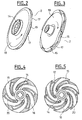
- Figures 2 and 3 show perspective views of the wheel 2.
- the arrow represented in these figures represents the direction of rotation of the impeller 2 in the pump 1, in this case anti-clockwise by observing the wheel from the inlet 11.
- Figures 4 and 5 show cross-sectional views of the following wheel 2 different axial positions.
- Figure 4 is a section of the wheel before the recess.
- Figure 5 is a section of the wheel at the recess.
- the Figure 6 shows a section of the wheel along a plane containing the axis of the wheel.
- the wheel has a fluid inlet 14, a radial opening 15 and at least one fluid channel 16 joining the fluid inlet 14 to the radial opening 15. The fluid sucked through the opening 14 thus crosses the channel 16, and is expelled from the wheel by the radial opening 15.
- the wheel 2 has a recess 17 at the periphery of the wheel.
- the recess is produced on a face of the wheel opposite to the entry face. This recess is angularly offset from the radial opening. Because of this setback, the fluid flow is disturbed and the bubbles and the fluid at the periphery of the wheel. The bubbles present in the fluid are thus driven to the pump outlet or the next impeller, if applicable.
- Lag angular allows the recovery of the fluid leaving a radial opening 15 by a recess 17 arranged angularly following the opening.
- the wheel has a fluid inlet face of the wheel formed by a first flange 18.
- Wheel 2 also has a second flange 19, forming the fluid discharge face of the wheel, in which the offset 17 is achieved.
- Several blades 20 are arranged between the flanges 18 and 19. The blades 20 delimit with the flanges 18 and 19 several channels 16.
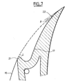
- the recess 17 preferably has a specific geometry, illustrated more specifically in Figure 7.
- the dotted lines represent the basic outline of a wheel 2 circular.
- the recess has a leading edge 21, which is angularly the closest to an opening 15 associated with the recess 17. It this is the leading edge in the direction of rotation of the wheel.
- This leading edge preferably forms an angle of attack, represented by ⁇ , between 80 and 100 ° with the periphery of the wheel.
- the periphery of the wheel is defined in the example by the circular outline of the wheel. This gives a good characteristic entrainment of bubbles by the fluid.
- the recess also has a trailing edge 22, which is angularly farthest from the opening 15 associated with the recess 17. It this is the trailing edge in the direction of rotation of the wheel.
- This trailing edge forms preferably a leak angle, represented by ⁇ , greater than 10 °.
- ⁇ a leak angle
- the leak angle is preferably less than 40 ° so maintain good hydraulic efficiency of the wheel. In order to get one again better hydraulic efficiency, the leak angle is preferably less than 25 °. The best compromise found between hydraulic efficiency and bubble evacuation was obtained in the example with a leak angle of 20 °.
- the recess preferably has a thickness along the axis of rotation of the wheel greater than 40% of the thickness of the channel along the same axis. Such a thickness allows to train enough fluid to evacuate bubbles.
- We preferably also uses a thickness along the axis of rotation of the wheel greater than 60% of the thickness of the channel along this same axis. Such a thickness helps maintain good hydraulic efficiency. The best compromise found between the hydraulic efficiency and the evacuation of bubbles was obtained with a thickness along the wheel axis equal to 50% of the thickness of the channel along the same axis.
- the recess preferably has a thickness along a radius between 9 and 14% of the diameter of the wheel. The greater the thickness, the better is operation, to the detriment of hydraulic efficiency.
- the recess preferably has a corresponding angular length at between 80 and 120% of the angular length of the fluid passage.
- a specific geometry of a blade 20 is preferably such that it does not not transform bubbles present at the fluid inlet into bubbles of smaller dimensions at the radial opening.
- a channel whose divergence is small.
- a channel 16 is used whose divergence between the fluid inlet and the fluid outlet is between 7 and 15 °.
- We express the divergence by the difference between the angular length at the entrance and at the radial opening. This maintains good fluid guidance in the channel. It results that the detachments are limited. Recirculations, causing braking bubbles to be evacuated are thus avoided.
- a divergence between the entry and the radial opening between 8 and 9 ° to limit even better the detachments.
- the wheel 2 is therefore particularly suitable for being mounted in a great suction height, that is to say greater than 4 meters.
- This wheel is by elsewhere particularly suitable for being mounted in a low flow pump, that is to say with a flow rate between 50 and 400 l / h.
- Wheel 2 improves the operation of a pump with a low flow rate and a large suction head, i.e. in aerated water.
- wheel 2 can improve the evacuation of bubbles, for example example of air bubbles, in operation at low flow and this, outside the priming period.
- a pump having several wheels as described above is a pump multicellular. It can have several wheels with return channels and broadcasters.
- the pump may if necessary have a fixed diffuser sandwiched between two wheels. This diffuser can be smooth or have fins of in a manner known per se.
Landscapes
- Engineering & Computer Science (AREA)
- Mechanical Engineering (AREA)
- General Engineering & Computer Science (AREA)
- Life Sciences & Earth Sciences (AREA)
- Sustainable Development (AREA)
- Structures Of Non-Positive Displacement Pumps (AREA)
- External Artificial Organs (AREA)
Abstract
Description
- figure 1, une vue en section transversale d'un exemple de pompe dans laquelle on peut monter une roue selon l'invention ;
- figure 2 et 3, des vues en perspective d'un exemple de roue de pompe selon l'invention ;
- figure 4, une vue en section transversale avant un décrochement d'une face d'évacuation de la roue ;
- figure 5, une vue en section transversale au niveau d'un décrochement d'une face d'évacuation de la roue ;
- figure 6, une vue en section transversale suivant un plan comprenant l'axe de la roue ;
- figure 7, un agrandissement d'un décrochement de la figure 5, représentant une géométrie préférentielle de ce décrochement.
Claims (12)
- Roue (2) de pompe hydraulique (1) comprenant :une entrée de fluide (14) sur une face;une ouverture radiale (15) ;au moins un canal de fluide (16) joignant l'entrée de fluide à l'ouverture radiale;un décrochement (17) à la périphérie de la roue, sur l'autre face de la roue, décalé angulairement par rapport à l'ouverture.
- La roue de la revendication 1, caractérisée en ce que l'angle de fuite, entre le décrochement et la périphérie de la roue dans le sens de rotation de la roue, est compris entre 10 et 40° et de préférence entre 15 et 25°.
- La roue de la revendication 1 ou 2, caractérisée en ce que l'angle d'attaque, entre le décrochement et la périphérie de la roue dans le sens de rotation de la roue, est compris entre 80 et 100°.
- La roue de la revendication 1, 2 ou 3, caractérisée en ce que le décrochement présente, suivant l'axe de rotation de la roue, une épaisseur comprise entre 40 et 60% de l'épaisseur du canal.
- La roue de l'une des revendications précédentes, caractérisée en ce que le décrochement présente une profondeur suivant un rayon compris entre 9 et 14% du diamètre de la roue.
- La roue de l'une des revendications précédentes, caractérisée en ce que le décrochement présente une longueur angulaire correspondant à entre 80 et 120 % de la longueur angulaire du passage de fluide.
- La roue de l'une des revendications précédentes, caractérisée en ce que l'aube définie entre deux canaux adjacents présente au voisinage de l'entrée de fluide un rayon de courbure compris entre 2 et 6 mm.
- La roue de la revendication 7, caractérisée en ce que la roue présente :un premier flasque sur lequel l'entrée est ménagée ;un deuxième flasque sur lequel le décrochement est ménagé ;au moins une aube et les premiers et deuxième flasques délimitant un desdits canaux.
- La roue de l'une des revendications précédentes, caractérisé en ce que le canal présente un angle de divergence compris entre 7 et 15°, de préférence entre 8 et 9°.
- Une pompe (1) présentant au moins une roue (2) selon l'une des revendications 1 à 9.
- La pompe de la revendication 10, caractérisée en ce qu'elle présente une hauteur d'aspiration supérieure à 4 mètres.
- La pompe de la revendication 10 ou 11, caractérisée en ce qu'elle présente un débit compris entre 50 et 400 l/h
Applications Claiming Priority (2)
| Application Number | Priority Date | Filing Date | Title |
|---|---|---|---|
| FR0204009 | 2002-03-27 | ||
| FR0204009A FR2837880B1 (fr) | 2002-03-27 | 2002-03-27 | Pompe pour faible debit et grande hauteur d'aspiration |
Publications (2)
| Publication Number | Publication Date |
|---|---|
| EP1348871A1 true EP1348871A1 (fr) | 2003-10-01 |
| EP1348871B1 EP1348871B1 (fr) | 2007-01-17 |
Family
ID=27799295
Family Applications (1)
| Application Number | Title | Priority Date | Filing Date |
|---|---|---|---|
| EP03290780A Expired - Lifetime EP1348871B1 (fr) | 2002-03-27 | 2003-03-27 | Pompe pour faible débit et grande hauteur d'aspiration |
Country Status (4)
| Country | Link |
|---|---|
| EP (1) | EP1348871B1 (fr) |
| AT (1) | ATE351984T1 (fr) |
| DE (1) | DE60311165T2 (fr) |
| FR (1) | FR2837880B1 (fr) |
Families Citing this family (5)
| Publication number | Priority date | Publication date | Assignee | Title |
|---|---|---|---|---|
| DK2218917T3 (da) | 2009-02-12 | 2013-07-08 | Ebm Papst Mulfingen Gmbh & Co | Radial- eller diagonal-ventilatorhjul |
| DE202010018509U1 (de) | 2010-02-26 | 2017-03-15 | Ebm-Papst Mulfingen Gmbh & Co. Kg | Radial- oder Diagonal-Ventilatorrad |
| CN106795891B (zh) | 2014-10-14 | 2020-11-10 | 株式会社荏原制作所 | 离心泵用的叶轮组件 |
| RU2610802C1 (ru) * | 2015-12-25 | 2017-02-15 | Андрей Юрьевич Языков | Рабочее колесо центробежного насоса |
| RU2610803C1 (ru) * | 2015-12-25 | 2017-02-15 | Андрей Юрьевич Языков | Рабочее колесо центробежного насоса |
Citations (4)
| Publication number | Priority date | Publication date | Assignee | Title |
|---|---|---|---|---|
| DE565019C (de) * | 1931-10-15 | 1932-12-22 | Fridolin Zehetmayer | Selbstansaugende Kreiselpumpe |
| FR742839A (fr) * | 1933-03-17 | |||
| GB877878A (en) * | 1958-06-03 | 1961-09-20 | Girdlestone Pumps Ltd | Improvements in or relating to centrifugal pumps |
| JPH10318180A (ja) * | 1997-03-19 | 1998-12-02 | Sankyo Seiki Mfg Co Ltd | 自吸式ポンプ |
-
2002
- 2002-03-27 FR FR0204009A patent/FR2837880B1/fr not_active Expired - Fee Related
-
2003
- 2003-03-27 EP EP03290780A patent/EP1348871B1/fr not_active Expired - Lifetime
- 2003-03-27 DE DE60311165T patent/DE60311165T2/de not_active Expired - Lifetime
- 2003-03-27 AT AT03290780T patent/ATE351984T1/de not_active IP Right Cessation
Patent Citations (4)
| Publication number | Priority date | Publication date | Assignee | Title |
|---|---|---|---|---|
| FR742839A (fr) * | 1933-03-17 | |||
| DE565019C (de) * | 1931-10-15 | 1932-12-22 | Fridolin Zehetmayer | Selbstansaugende Kreiselpumpe |
| GB877878A (en) * | 1958-06-03 | 1961-09-20 | Girdlestone Pumps Ltd | Improvements in or relating to centrifugal pumps |
| JPH10318180A (ja) * | 1997-03-19 | 1998-12-02 | Sankyo Seiki Mfg Co Ltd | 自吸式ポンプ |
Non-Patent Citations (1)
| Title |
|---|
| PATENT ABSTRACTS OF JAPAN vol. 1999, no. 03 31 March 1999 (1999-03-31) * |
Also Published As
| Publication number | Publication date |
|---|---|
| FR2837880A1 (fr) | 2003-10-03 |
| DE60311165T2 (de) | 2008-01-10 |
| DE60311165D1 (de) | 2007-03-08 |
| ATE351984T1 (de) | 2007-02-15 |
| FR2837880B1 (fr) | 2005-12-09 |
| EP1348871B1 (fr) | 2007-01-17 |
Similar Documents
| Publication | Publication Date | Title |
|---|---|---|
| EP1138954B1 (fr) | Ventilateur centrifuge | |
| EP2710268B1 (fr) | Procédé de soufflage dans un diffuseur de turbine à gaz et diffuseur correspondant | |
| EP3253970B1 (fr) | Aube de soufflante | |
| WO2014154997A1 (fr) | Diffuseur à ailettes d'un compresseur radial ou mixte | |
| FR2730007A1 (fr) | Machine a ecoulement radial | |
| EP0303543B1 (fr) | Ventilateur à courant transversal | |
| FR2961564A1 (fr) | Compresseur et turbomachine a rendement optimise | |
| FR2481378A1 (fr) | Ventilateur a courant transversal | |
| FR3065497B1 (fr) | Canal d'ejection d'air vers le sommet et vers l'aval d'une pale d'aube de turbomachine | |
| EP1348871B1 (fr) | Pompe pour faible débit et grande hauteur d'aspiration | |
| EP3794223B1 (fr) | Module d'échangeur de chaleur pour vehicule automobile | |
| EP3719283B1 (fr) | Pignon d'entrainement d'un séparateur air/huile d'un boitier d'accessoires de turbomachine | |
| FR2958346A1 (fr) | Compresseur de turbomachine | |
| FR2661217A1 (fr) | Amelioration dans un compresseur du type a chambre torouidale de regeneration. | |
| FR3089576A1 (fr) | Rouet centrifuge | |
| FR2575235A1 (fr) | Turbine de pompe centrifuge | |
| FR2970508A1 (fr) | Assemblage de compression et turbomoteur equipe d'un tel assemblage | |
| FR3081027A1 (fr) | Turbomachine comportant un circuit de prelevement d'air | |
| EP0360681B1 (fr) | Roue de pompe Vortex | |
| FR3168235A1 (fr) | Aubage pour une turbomachine d’aéronef | |
| BE448094A (fr) | ||
| FR3149650A1 (fr) | Traitement de carter non axisymétrique avec plenum ondulé | |
| WO2026013350A1 (fr) | Carter a fentes vrillees avec plenum | |
| FR2984426A1 (fr) | Dispositif de ventilation a double turbine a aubes decalees | |
| FR2927673A1 (fr) | Aube de soufflante avec aspiration en pied et soufflage en tete |
Legal Events
| Date | Code | Title | Description |
|---|---|---|---|
| PUAI | Public reference made under article 153(3) epc to a published international application that has entered the european phase |
Free format text: ORIGINAL CODE: 0009012 |
|
| AK | Designated contracting states |
Kind code of ref document: A1 Designated state(s): AT BE BG CH CY CZ DE DK EE ES FI FR GB GR HU IE IT LI LU MC NL PT RO SE SI SK TR |
|
| AX | Request for extension of the european patent |
Extension state: AL LT LV MK |
|
| 17P | Request for examination filed |
Effective date: 20040401 |
|
| AKX | Designation fees paid |
Designated state(s): AT BE BG CH CY CZ DE DK EE ES FI FR GB GR HU IE IT LI LU MC NL PT RO SE SI SK TR |
|
| GRAP | Despatch of communication of intention to grant a patent |
Free format text: ORIGINAL CODE: EPIDOSNIGR1 |
|
| GRAS | Grant fee paid |
Free format text: ORIGINAL CODE: EPIDOSNIGR3 |
|
| GRAA | (expected) grant |
Free format text: ORIGINAL CODE: 0009210 |
|
| AK | Designated contracting states |
Kind code of ref document: B1 Designated state(s): AT BE BG CH CY CZ DE DK EE ES FI FR GB GR HU IE IT LI LU MC NL PT RO SE SI SK TR |
|
| PG25 | Lapsed in a contracting state [announced via postgrant information from national office to epo] |
Ref country code: AT Free format text: LAPSE BECAUSE OF FAILURE TO SUBMIT A TRANSLATION OF THE DESCRIPTION OR TO PAY THE FEE WITHIN THE PRESCRIBED TIME-LIMIT Effective date: 20070117 Ref country code: IE Free format text: LAPSE BECAUSE OF FAILURE TO SUBMIT A TRANSLATION OF THE DESCRIPTION OR TO PAY THE FEE WITHIN THE PRESCRIBED TIME-LIMIT Effective date: 20070117 Ref country code: DK Free format text: LAPSE BECAUSE OF FAILURE TO SUBMIT A TRANSLATION OF THE DESCRIPTION OR TO PAY THE FEE WITHIN THE PRESCRIBED TIME-LIMIT Effective date: 20070117 Ref country code: NL Free format text: LAPSE BECAUSE OF FAILURE TO SUBMIT A TRANSLATION OF THE DESCRIPTION OR TO PAY THE FEE WITHIN THE PRESCRIBED TIME-LIMIT Effective date: 20070117 Ref country code: SI Free format text: LAPSE BECAUSE OF FAILURE TO SUBMIT A TRANSLATION OF THE DESCRIPTION OR TO PAY THE FEE WITHIN THE PRESCRIBED TIME-LIMIT Effective date: 20070117 Ref country code: FI Free format text: LAPSE BECAUSE OF FAILURE TO SUBMIT A TRANSLATION OF THE DESCRIPTION OR TO PAY THE FEE WITHIN THE PRESCRIBED TIME-LIMIT Effective date: 20070117 |
|
| REG | Reference to a national code |
Ref country code: GB Ref legal event code: FG4D Free format text: NOT ENGLISH |
|
| REG | Reference to a national code |
Ref country code: CH Ref legal event code: EP |
|
| REG | Reference to a national code |
Ref country code: IE Ref legal event code: FG4D Free format text: LANGUAGE OF EP DOCUMENT: FRENCH |
|
| REF | Corresponds to: |
Ref document number: 60311165 Country of ref document: DE Date of ref document: 20070308 Kind code of ref document: P |
|
| GBT | Gb: translation of ep patent filed (gb section 77(6)(a)/1977) |
Effective date: 20070307 |
|
| PG25 | Lapsed in a contracting state [announced via postgrant information from national office to epo] |
Ref country code: SE Free format text: LAPSE BECAUSE OF FAILURE TO SUBMIT A TRANSLATION OF THE DESCRIPTION OR TO PAY THE FEE WITHIN THE PRESCRIBED TIME-LIMIT Effective date: 20070417 |
|
| PG25 | Lapsed in a contracting state [announced via postgrant information from national office to epo] |
Ref country code: BG Free format text: LAPSE BECAUSE OF EXPIRATION OF PROTECTION Effective date: 20070418 |
|
| PG25 | Lapsed in a contracting state [announced via postgrant information from national office to epo] |
Ref country code: ES Free format text: LAPSE BECAUSE OF FAILURE TO SUBMIT A TRANSLATION OF THE DESCRIPTION OR TO PAY THE FEE WITHIN THE PRESCRIBED TIME-LIMIT Effective date: 20070428 |
|
| PG25 | Lapsed in a contracting state [announced via postgrant information from national office to epo] |
Ref country code: PT Free format text: LAPSE BECAUSE OF FAILURE TO SUBMIT A TRANSLATION OF THE DESCRIPTION OR TO PAY THE FEE WITHIN THE PRESCRIBED TIME-LIMIT Effective date: 20070618 |
|
| NLV1 | Nl: lapsed or annulled due to failure to fulfill the requirements of art. 29p and 29m of the patents act | ||
| REG | Reference to a national code |
Ref country code: IE Ref legal event code: FD4D |
|
| REG | Reference to a national code |
Ref country code: CH Ref legal event code: PL |
|
| PLBE | No opposition filed within time limit |
Free format text: ORIGINAL CODE: 0009261 |
|
| STAA | Information on the status of an ep patent application or granted ep patent |
Free format text: STATUS: NO OPPOSITION FILED WITHIN TIME LIMIT |
|
| PG25 | Lapsed in a contracting state [announced via postgrant information from national office to epo] |
Ref country code: SK Free format text: LAPSE BECAUSE OF FAILURE TO SUBMIT A TRANSLATION OF THE DESCRIPTION OR TO PAY THE FEE WITHIN THE PRESCRIBED TIME-LIMIT Effective date: 20070117 |
|
| 26N | No opposition filed |
Effective date: 20071018 |
|
| BERE | Be: lapsed |
Owner name: POMPES SALMSON Effective date: 20070331 |
|
| PG25 | Lapsed in a contracting state [announced via postgrant information from national office to epo] |
Ref country code: RO Free format text: LAPSE BECAUSE OF FAILURE TO SUBMIT A TRANSLATION OF THE DESCRIPTION OR TO PAY THE FEE WITHIN THE PRESCRIBED TIME-LIMIT Effective date: 20070117 Ref country code: BE Free format text: LAPSE BECAUSE OF NON-PAYMENT OF DUE FEES Effective date: 20070331 Ref country code: CZ Free format text: LAPSE BECAUSE OF FAILURE TO SUBMIT A TRANSLATION OF THE DESCRIPTION OR TO PAY THE FEE WITHIN THE PRESCRIBED TIME-LIMIT Effective date: 20070117 |
|
| PG25 | Lapsed in a contracting state [announced via postgrant information from national office to epo] |
Ref country code: MC Free format text: LAPSE BECAUSE OF NON-PAYMENT OF DUE FEES Effective date: 20070331 |
|
| PG25 | Lapsed in a contracting state [announced via postgrant information from national office to epo] |
Ref country code: LI Free format text: LAPSE BECAUSE OF NON-PAYMENT OF DUE FEES Effective date: 20070331 Ref country code: CH Free format text: LAPSE BECAUSE OF NON-PAYMENT OF DUE FEES Effective date: 20070331 |
|
| PG25 | Lapsed in a contracting state [announced via postgrant information from national office to epo] |
Ref country code: GR Free format text: LAPSE BECAUSE OF FAILURE TO SUBMIT A TRANSLATION OF THE DESCRIPTION OR TO PAY THE FEE WITHIN THE PRESCRIBED TIME-LIMIT Effective date: 20070418 |
|
| PG25 | Lapsed in a contracting state [announced via postgrant information from national office to epo] |
Ref country code: EE Free format text: LAPSE BECAUSE OF FAILURE TO SUBMIT A TRANSLATION OF THE DESCRIPTION OR TO PAY THE FEE WITHIN THE PRESCRIBED TIME-LIMIT Effective date: 20070117 |
|
| PG25 | Lapsed in a contracting state [announced via postgrant information from national office to epo] |
Ref country code: CY Free format text: LAPSE BECAUSE OF FAILURE TO SUBMIT A TRANSLATION OF THE DESCRIPTION OR TO PAY THE FEE WITHIN THE PRESCRIBED TIME-LIMIT Effective date: 20070117 |
|
| PG25 | Lapsed in a contracting state [announced via postgrant information from national office to epo] |
Ref country code: LU Free format text: LAPSE BECAUSE OF NON-PAYMENT OF DUE FEES Effective date: 20070327 |
|
| PG25 | Lapsed in a contracting state [announced via postgrant information from national office to epo] |
Ref country code: HU Free format text: LAPSE BECAUSE OF FAILURE TO SUBMIT A TRANSLATION OF THE DESCRIPTION OR TO PAY THE FEE WITHIN THE PRESCRIBED TIME-LIMIT Effective date: 20070718 Ref country code: TR Free format text: LAPSE BECAUSE OF FAILURE TO SUBMIT A TRANSLATION OF THE DESCRIPTION OR TO PAY THE FEE WITHIN THE PRESCRIBED TIME-LIMIT Effective date: 20070117 |
|
| REG | Reference to a national code |
Ref country code: FR Ref legal event code: PLFP Year of fee payment: 13 |
|
| PGFP | Annual fee paid to national office [announced via postgrant information from national office to epo] |
Ref country code: IT Payment date: 20150223 Year of fee payment: 13 Ref country code: DE Payment date: 20150324 Year of fee payment: 13 |
|
| PGFP | Annual fee paid to national office [announced via postgrant information from national office to epo] |
Ref country code: GB Payment date: 20150325 Year of fee payment: 13 Ref country code: FR Payment date: 20150302 Year of fee payment: 13 |
|
| REG | Reference to a national code |
Ref country code: DE Ref legal event code: R119 Ref document number: 60311165 Country of ref document: DE |
|
| GBPC | Gb: european patent ceased through non-payment of renewal fee |
Effective date: 20160327 |
|
| REG | Reference to a national code |
Ref country code: FR Ref legal event code: ST Effective date: 20161130 |
|
| PG25 | Lapsed in a contracting state [announced via postgrant information from national office to epo] |
Ref country code: DE Free format text: LAPSE BECAUSE OF NON-PAYMENT OF DUE FEES Effective date: 20161001 Ref country code: GB Free format text: LAPSE BECAUSE OF NON-PAYMENT OF DUE FEES Effective date: 20160327 Ref country code: FR Free format text: LAPSE BECAUSE OF NON-PAYMENT OF DUE FEES Effective date: 20160331 |
|
| PG25 | Lapsed in a contracting state [announced via postgrant information from national office to epo] |
Ref country code: IT Free format text: LAPSE BECAUSE OF NON-PAYMENT OF DUE FEES Effective date: 20160327 |