EP1348829A2 - Dispositif antivibratoire pour hayon de véhicule - Google Patents
Dispositif antivibratoire pour hayon de véhicule Download PDFInfo
- Publication number
- EP1348829A2 EP1348829A2 EP03290792A EP03290792A EP1348829A2 EP 1348829 A2 EP1348829 A2 EP 1348829A2 EP 03290792 A EP03290792 A EP 03290792A EP 03290792 A EP03290792 A EP 03290792A EP 1348829 A2 EP1348829 A2 EP 1348829A2
- Authority
- EP
- European Patent Office
- Prior art keywords
- tailgate
- stop
- presser
- trigger guard
- fixed
- Prior art date
- Legal status (The legal status is an assumption and is not a legal conclusion. Google has not performed a legal analysis and makes no representation as to the accuracy of the status listed.)
- Granted
Links
Images

Classifications
-
- E—FIXED CONSTRUCTIONS
- E05—LOCKS; KEYS; WINDOW OR DOOR FITTINGS; SAFES
- E05F—DEVICES FOR MOVING WINGS INTO OPEN OR CLOSED POSITION; CHECKS FOR WINGS; WING FITTINGS NOT OTHERWISE PROVIDED FOR, CONCERNED WITH THE FUNCTIONING OF THE WING
- E05F7/00—Accessories for wings not provided for in other groups of this subclass
- E05F7/04—Arrangements affording protection against rattling
-
- E—FIXED CONSTRUCTIONS
- E05—LOCKS; KEYS; WINDOW OR DOOR FITTINGS; SAFES
- E05F—DEVICES FOR MOVING WINGS INTO OPEN OR CLOSED POSITION; CHECKS FOR WINGS; WING FITTINGS NOT OTHERWISE PROVIDED FOR, CONCERNED WITH THE FUNCTIONING OF THE WING
- E05F5/00—Braking devices, e.g. checks; Stops; Buffers
- E05F5/02—Braking devices, e.g. checks; Stops; Buffers specially for preventing the slamming of swinging wings during final closing movement, e.g. jamb stops
- E05F5/022—Braking devices, e.g. checks; Stops; Buffers specially for preventing the slamming of swinging wings during final closing movement, e.g. jamb stops specially adapted for vehicles, e.g. for hoods or trunks
-
- E—FIXED CONSTRUCTIONS
- E05—LOCKS; KEYS; WINDOW OR DOOR FITTINGS; SAFES
- E05Y—INDEXING SCHEME ASSOCIATED WITH SUBCLASSES E05D AND E05F, RELATING TO CONSTRUCTION ELEMENTS, ELECTRIC CONTROL, POWER SUPPLY, POWER SIGNAL OR TRANSMISSION, USER INTERFACES, MOUNTING OR COUPLING, DETAILS, ACCESSORIES, AUXILIARY OPERATIONS NOT OTHERWISE PROVIDED FOR, APPLICATION THEREOF
- E05Y2900/00—Application of doors, windows, wings or fittings thereof
- E05Y2900/50—Application of doors, windows, wings or fittings thereof for vehicles
- E05Y2900/53—Type of wing
- E05Y2900/546—Tailboards, tailgates or sideboards opening upwards
Definitions
- the present invention relates to a device for preventing a tailgate to vibrate when it is in the closed state.
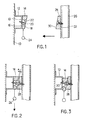
- Figures 1 to 3 respectively represent a schematic sectional view of the known device with the tailgate open, a sectional view of the device with the tailgate closed, before adjustment and a section after adjustment.
- a sheet metal part 12 in the shape of an ⁇ trigger guard.
- a wedge-shaped stop 14 On the central wall 13 of the trigger guard is fixed by a first face 16 a wedge-shaped stop 14 whose other face 18 is inclined from the first side at an acute angle of a few degrees.
- the stop 14 is fixed to the trigger guard by means of a screw 20 or similar, passing through an oblong hole 22 drilled in the stop.
- the stopper is provided at its narrow end with a snap-off pull tab 24.
- the tailgate 26 is provided with a second stop 28 also wedge-shaped, the two faces 30, 32 of which form between them the same angle as the faces 16, 18 of the first stop.
- the stops 14 and 28 are fixed so that, when the tailgate is in the closed position, as shown in Figure 2, their respective inclined faces 18, 30 are applied to each other by their entire surface. However, in most cases, this is not the case, as it usually remains between these sides an e relatively small stake.
- the operator who is stationed on the assembly line proceeds as follows: the screw 20 being in the loose state, it exerts traction on the pull tab 24, which causes a slight displacement of the first stop 14 , until its inclined face 18 is applied to the inclined face 30 of the second stop, as shown in FIG. 3. The operator then opens the tailgate, tightens the screw 20 strongly to lock the stop 14 in its final position and snaps the pull tab.
- This device effectively eliminates tailgate vibrations since there is no more play between the stops, but it has the disadvantage that the sheet metal trigger guard forms an aggressive projection in the boot which risks injure the operators who are stationed along the chain mounting.
- the weld area between the first stop and the trigger guard must undergo an anti-corrosion treatment to avoid the appearance of rust and must be chewed to guarantee a good seal at the welding. But these treatments are expensive and delay the production.
- the trigger guard and the boot stopper can be pre-assembled to the presser by the supplier, so that, on the assembly line, we just have to connect the body to the rear bumper using the presser. The trigger guard and the boot stopper are then in place. This pre-assembly saves a lot of time and silver.
- the trigger guard can be attached on the plastic presser other than by welding, by example by screwing or riveting. It is therefore no longer necessary to perform a corrosion treatment on the contact area between the trigger guard and the presser, or chew this area.
- FIG. 4 This figure represents a rear shield 10 seen from inside the trunk of a vehicle.
- the rear bumper is connected to the body 44 at the by means of an arcuate hollow piece 46 of plastic material, known as the name of the bail.
- the presser is fixed on the inside wall of the rear bumper, of which it follows the shape, its cavity being turned towards the shield.
- the presser is provided for this purpose with hooks 48 which are capable of hook into holes 50 formed on the edge of the rear bumper and lugs 52 by means of which it is fixed to the body 44.
- the presser is fixed so that one of its ends projects in the trunk opening. This end is closed by a wall terminal 54 which is pierced with an orifice 56, visible in FIG. 6.
- a support part 60 formed by two square walls 62, 64.
- One of these walls 62 is screwed, riveted or fixed otherwise than by welding on the bottom wall 58 of the presser, while the second wall 64 is applied to the end wall 54 of the presser.
- This second wall carries an ⁇ part or trigger guard 66 a portion of which projects through the orifice 56 of the end wall.
- the trigger guard therefore forms a slight prominence on the edge of the rear bumper, in the opening of the trunk.
- the trigger guard itself carries a trunk stop 68 in the form of a wedge.
- the position of the stopper on the trigger guard can be adjusted by the fact that the stopper is fixed thereon by means of a screw 69 or the like, passing through an oblong hole 70. When the screw is loose, the stop 68 can be slid over the trigger guard.
- Another wedge-shaped stop 72 is fixed on the edge of the tailgate 74.
- the stops 68 and 72 are fixed so that their respective inclined faces come opposite each other, when the tailgate is closed. Generally, these faces are separated by a small interval that we can be removed by moving the trunk stop 68 with a pull tab 80, while the tailgate is closed, until the inclined face of the boot stopper applies to that of the tailgate stopper.
Landscapes
- Superstructure Of Vehicle (AREA)
- Lock And Its Accessories (AREA)
- Vehicle Step Arrangements And Article Storage (AREA)
Abstract
- une pièce de liaison ou presseur (46) réalisée en matière plastique et servant à relier le bouclier arrière (10) du véhicule à la carrosserie,
- une pièce support sur laquelle est fixé un pontet (66) en forme de Ω,
- une butée de coffre (70) fixée sur la portion saillante du pontet au moyen d'une fixation desserrable (69) qui permet un réglage de la position de la butée de coffre,
et un élément de traction (80) au moyen duquel la butée de coffre peut être tirée.
Description
- une pièce de liaison creuse ou presseur, réalisée en matière plastique et servant à relier le bouclier arrière du véhicule à la carrosserie, ladite pièce comportant une paroi de fond tournée vers l'intérieur du coffre et une paroi d'extrémité sur laquelle est percée une ouverture, et qui se trouve en regard du bord de l'ouverture du coffre,
- une pièce support sur laquelle est fixé un pontet en forme de Ω, la pièce support et le pontet étant insérés dans la cavité du presseur de manière que le pontet fasse saillie à travers ladite ouverture,
- une butée de coffre fixée sur la portion saillante du pontet au moyen d'une fixation desserrable qui permet un réglage de la position de la butée de coffre,
et un élément de traction au moyen duquel la butée de coffre peut être déplacée, après que le hayon a été fermé, jusqu'à ce qu'elle vienne en contact avec la butée de hayon.
- le pontet 66 n'est plus fixé sur le bouclier arrière, mais il est intégré à l'intérieur du presseur. De ce fait, il ne constitue plus une saillie agressive, et cela d'autant plus que le presseur dans lequel se trouve le pontet n'est monté qu'au moment où la carrosserie doit être assemblée au bouclier arrière,
- le pontet n'est plus soudé sur une surface métallique, mais il est fixé sur le presseur en matière plastique par un mode de fixation autre que la soudure. Il n'est donc plus nécessaire d'effectuer un traitement contre la corrosion, ni d'étanchéifier la zone de contact entre le pontet et le presseur,
- le pontet peut être préassemblé au presseur et fourni prêt à être monté.
Claims (3)
- Dispositif antivibratoire pour hayon de véhicule, caractérisé en ce qu'il comprend :une butée de hayon (72) fixée sur le hayon (74),une pièce de liaison ou presseur (46) réalisée en matière plastique et servant à relier le bouclier arrière (10) du véhicule à la carrosserie (44), ladite pièce comportant une paroi de fond (58) tournée vers l'intérieur du coffre et une paroi d'extrémité (54) sur laquelle est percée une ouverture (56) et qui se trouve en regard du bord de l'ouverture du coffre,une pièce support (60) sur laquelle est fixé un pontet (66) en forme de Ω, la pièce support et le pontet étant insérés dans la cavité du presseur de manière que le pontet fasse saillie à travers ladite ouverture (56),une butée de coffre (70) fixée sur la portion saillante du pontet au moyen d'une fixation desserrable (69) qui permet un réglage de la position de la butée de coffre,
et un élément de traction (80) au moyen duquel la butée de coffre peut être tirée, après que le hayon a été fermé, jusqu'à ce qu'elle vienne en contact avec la butée de hayon. - Dispositif antivibratoire selon la revendication 1, caractérisé en ce que la pièce support (60) comporte deux parois en équerre (62, 64), l'une de ces parois (62) étant fixée sur la paroi de fond du presseur (58) par un moyen de fixation autre que la soudure et l'autre paroi (64) étant appliquée sur la paroi terminale (54) du presseur.
- Application du dispositif antivibratoire selon l'une des revendications 1 et 2 à l'élimination des vibrations du hayon et des portes latérales d'un véhicule.
Applications Claiming Priority (2)
| Application Number | Priority Date | Filing Date | Title |
|---|---|---|---|
| FR0204000A FR2837779B1 (fr) | 2002-03-29 | 2002-03-29 | Dispositif antivibratoire pour hayon de vehicule |
| FR0204000 | 2002-03-29 |
Publications (3)
| Publication Number | Publication Date |
|---|---|
| EP1348829A2 true EP1348829A2 (fr) | 2003-10-01 |
| EP1348829A3 EP1348829A3 (fr) | 2003-12-10 |
| EP1348829B1 EP1348829B1 (fr) | 2005-10-19 |
Family
ID=27799293
Family Applications (1)
| Application Number | Title | Priority Date | Filing Date |
|---|---|---|---|
| EP20030290792 Expired - Lifetime EP1348829B1 (fr) | 2002-03-29 | 2003-03-28 | Dispositif antivibratoire pour hayon de véhicule |
Country Status (4)
| Country | Link |
|---|---|
| EP (1) | EP1348829B1 (fr) |
| DE (1) | DE60301900T2 (fr) |
| ES (1) | ES2251669T3 (fr) |
| FR (1) | FR2837779B1 (fr) |
Family Cites Families (2)
| Publication number | Priority date | Publication date | Assignee | Title |
|---|---|---|---|---|
| FR2707944B1 (fr) * | 1993-07-20 | 1995-10-20 | Itw De France | Butée réglable, système de butées la comportant et procédé pour obtenir un tel système. |
| JP3812923B2 (ja) * | 1998-05-26 | 2006-08-23 | 富士重工業株式会社 | 自動車用バンパ表皮の補強構造 |
-
2002
- 2002-03-29 FR FR0204000A patent/FR2837779B1/fr not_active Expired - Fee Related
-
2003
- 2003-03-28 DE DE2003601900 patent/DE60301900T2/de not_active Expired - Fee Related
- 2003-03-28 EP EP20030290792 patent/EP1348829B1/fr not_active Expired - Lifetime
- 2003-03-28 ES ES03290792T patent/ES2251669T3/es not_active Expired - Lifetime
Also Published As
| Publication number | Publication date |
|---|---|
| EP1348829B1 (fr) | 2005-10-19 |
| FR2837779A1 (fr) | 2003-10-03 |
| FR2837779B1 (fr) | 2004-08-13 |
| ES2251669T3 (es) | 2006-05-01 |
| DE60301900D1 (de) | 2006-03-02 |
| DE60301900T2 (de) | 2006-07-20 |
| EP1348829A3 (fr) | 2003-12-10 |
Similar Documents
| Publication | Publication Date | Title |
|---|---|---|
| EP0970854B1 (fr) | Dispositif de fixation des crosses d'un pare-chocs sur une aile de carrosserie de véhicule | |
| FR2461842A1 (fr) | Goujon-rivet pour fixation de panneaux entre eux | |
| EP4313690B1 (fr) | Peau de pare-chocs de véhicule automobile | |
| FR2857314A1 (fr) | Dispositif de fixation des parties laterales en forme de crosse du pare-chocs avant d'un vehicule automobile aux ailes de ce dernier | |
| WO2018146416A1 (fr) | Dispositif de maintien en position entrebâillée d'un ouvrant sur un élément fixe d'une caisse d'un véhicule | |
| EP0544376B1 (fr) | Attache de fixation d'une pièce munie d'une tige sur une paroi | |
| EP1348829B1 (fr) | Dispositif antivibratoire pour hayon de véhicule | |
| EP1798122B1 (fr) | Moyen de fixation d'une sangle de ceinture de sécurité | |
| FR3073193B1 (fr) | Fixation de carrosserie de vehicule automobile a une pointe d’aile arriere | |
| FR2890932A1 (fr) | Montant de baie d'une caisse de vehicule automobile | |
| EP3007935B1 (fr) | Garniture en matière plastique destinée à etre fixée sur la partie inférieure de la face intérieure du volet arrière d'un véhicule automobile | |
| FR2994932A1 (fr) | Dispositif d'assemblage par glissement de deux pieces de vehicule | |
| EP1871966B1 (fr) | Dispositif d'articulation esthétique pour porte de véhicule automobile | |
| EP1477355B1 (fr) | Porte de vèhicule comprenant des moyens d'inviolabilitè de la partie supèrieure d'une vitre affleurante, extension d'inviolabilitè et vèhicule correspondants. | |
| EP1568835A1 (fr) | Butée de limitation de débattement transversal d'une vitre coulissante d'une porte d'un véhicule automobile | |
| FR2890409A1 (fr) | Butee de volet roulant, procede de mise en place de la butee et volet roulant ainsi equipe | |
| FR3061248A1 (fr) | Element d'attache pour cordon de retenue d'une trappe d'obturation d'une piece automobile | |
| FR3039106A1 (fr) | Agencement d'un element de garniture autour d'une charniere de coffre de vehicule automobile | |
| FR2464843A1 (fr) | Toit ouvrant de vehicules avec un pavillon articule et amovible | |
| FR3134771A1 (fr) | Support latéral de pare-chocs pour véhicule automobile | |
| EP2013048A1 (fr) | Dispositif en bande comportant un materiau adhesif, procede de pose dans un vehicule | |
| FR2911110A1 (fr) | Equerre de maintien d'un element de carrosserie d'un vehicule en matiere plastique, et son utilisation au maintien d'une aile. | |
| FR2935940A1 (fr) | Dispositif de masquage d'un coussin gonflable de securite pour vehicule automobile, planche de bord et vehicule correspondants. | |
| EP1452373A1 (fr) | Elément de fixation d'extrémité de joint de porte | |
| FR2867441A1 (fr) | Carrosserie d'un vehicule comprenant une aile et un support d'aile |
Legal Events
| Date | Code | Title | Description |
|---|---|---|---|
| PUAI | Public reference made under article 153(3) epc to a published international application that has entered the european phase |
Free format text: ORIGINAL CODE: 0009012 |
|
| AK | Designated contracting states |
Kind code of ref document: A2 Designated state(s): AT BE BG CH CY CZ DE DK EE ES FI FR GB GR HU IE IT LI LU MC NL PT RO SE SI SK TR |
|
| AX | Request for extension of the european patent |
Extension state: AL LT LV MK |
|
| PUAL | Search report despatched |
Free format text: ORIGINAL CODE: 0009013 |
|
| AK | Designated contracting states |
Kind code of ref document: A3 Designated state(s): AT BE BG CH CY CZ DE DK EE ES FI FR GB GR HU IE IT LI LU MC NL PT RO SE SI SK TR |
|
| AX | Request for extension of the european patent |
Extension state: AL LT LV MK |
|
| 17P | Request for examination filed |
Effective date: 20040409 |
|
| RAP1 | Party data changed (applicant data changed or rights of an application transferred) |
Owner name: PEGUFORM FRANCE Owner name: RENAULT S.A. |
|
| AKX | Designation fees paid |
Designated state(s): BE DE ES FR GB IT |
|
| RAP1 | Party data changed (applicant data changed or rights of an application transferred) |
Owner name: PEGUFORM FRANCE Owner name: RENAULT S.A.S. |
|
| GRAP | Despatch of communication of intention to grant a patent |
Free format text: ORIGINAL CODE: EPIDOSNIGR1 |
|
| GRAS | Grant fee paid |
Free format text: ORIGINAL CODE: EPIDOSNIGR3 |
|
| GRAA | (expected) grant |
Free format text: ORIGINAL CODE: 0009210 |
|
| AK | Designated contracting states |
Kind code of ref document: B1 Designated state(s): BE DE ES FR GB IT |
|
| REG | Reference to a national code |
Ref country code: GB Ref legal event code: FG4D Free format text: NOT ENGLISH |
|
| GBT | Gb: translation of ep patent filed (gb section 77(6)(a)/1977) |
Effective date: 20060130 |
|
| REF | Corresponds to: |
Ref document number: 60301900 Country of ref document: DE Date of ref document: 20060302 Kind code of ref document: P |
|
| REG | Reference to a national code |
Ref country code: ES Ref legal event code: FG2A Ref document number: 2251669 Country of ref document: ES Kind code of ref document: T3 |
|
| PLBE | No opposition filed within time limit |
Free format text: ORIGINAL CODE: 0009261 |
|
| STAA | Information on the status of an ep patent application or granted ep patent |
Free format text: STATUS: NO OPPOSITION FILED WITHIN TIME LIMIT |
|
| 26N | No opposition filed |
Effective date: 20060720 |
|
| PGFP | Annual fee paid to national office [announced via postgrant information from national office to epo] |
Ref country code: ES Payment date: 20090324 Year of fee payment: 7 |
|
| PGFP | Annual fee paid to national office [announced via postgrant information from national office to epo] |
Ref country code: DE Payment date: 20090320 Year of fee payment: 7 |
|
| PG25 | Lapsed in a contracting state [announced via postgrant information from national office to epo] |
Ref country code: DE Free format text: LAPSE BECAUSE OF NON-PAYMENT OF DUE FEES Effective date: 20101001 |
|
| REG | Reference to a national code |
Ref country code: ES Ref legal event code: FD2A Effective date: 20110415 |
|
| PG25 | Lapsed in a contracting state [announced via postgrant information from national office to epo] |
Ref country code: ES Free format text: LAPSE BECAUSE OF NON-PAYMENT OF DUE FEES Effective date: 20110404 |
|
| PGFP | Annual fee paid to national office [announced via postgrant information from national office to epo] |
Ref country code: FR Payment date: 20110414 Year of fee payment: 9 |
|
| PG25 | Lapsed in a contracting state [announced via postgrant information from national office to epo] |
Ref country code: ES Free format text: LAPSE BECAUSE OF NON-PAYMENT OF DUE FEES Effective date: 20100329 |
|
| PGFP | Annual fee paid to national office [announced via postgrant information from national office to epo] |
Ref country code: GB Payment date: 20120322 Year of fee payment: 10 Ref country code: BE Payment date: 20120329 Year of fee payment: 10 |
|
| PGFP | Annual fee paid to national office [announced via postgrant information from national office to epo] |
Ref country code: IT Payment date: 20120328 Year of fee payment: 10 |
|
| REG | Reference to a national code |
Ref country code: FR Ref legal event code: ST Effective date: 20121130 |
|
| PG25 | Lapsed in a contracting state [announced via postgrant information from national office to epo] |
Ref country code: FR Free format text: LAPSE BECAUSE OF NON-PAYMENT OF DUE FEES Effective date: 20120402 |
|
| BERE | Be: lapsed |
Owner name: *RENAULT S.A.S. Effective date: 20130331 Owner name: *PEGUFORM FRANCE Effective date: 20130331 |
|
| GBPC | Gb: european patent ceased through non-payment of renewal fee |
Effective date: 20130328 |
|
| PG25 | Lapsed in a contracting state [announced via postgrant information from national office to epo] |
Ref country code: BE Free format text: LAPSE BECAUSE OF NON-PAYMENT OF DUE FEES Effective date: 20130331 Ref country code: GB Free format text: LAPSE BECAUSE OF NON-PAYMENT OF DUE FEES Effective date: 20130328 |
|
| PG25 | Lapsed in a contracting state [announced via postgrant information from national office to epo] |
Ref country code: IT Free format text: LAPSE BECAUSE OF NON-PAYMENT OF DUE FEES Effective date: 20130328 |