EP1347103A2 - Control of an operating arm of an earthmoving vehicle - Google Patents
Control of an operating arm of an earthmoving vehicle Download PDFInfo
- Publication number
- EP1347103A2 EP1347103A2 EP03075645A EP03075645A EP1347103A2 EP 1347103 A2 EP1347103 A2 EP 1347103A2 EP 03075645 A EP03075645 A EP 03075645A EP 03075645 A EP03075645 A EP 03075645A EP 1347103 A2 EP1347103 A2 EP 1347103A2
- Authority
- EP
- European Patent Office
- Prior art keywords
- control means
- chamber
- operating arm
- drain line
- vehicle
- Prior art date
- Legal status (The legal status is an assumption and is not a legal conclusion. Google has not performed a legal analysis and makes no representation as to the accuracy of the status listed.)
- Withdrawn
Links
Images

Classifications
-
- E—FIXED CONSTRUCTIONS
- E02—HYDRAULIC ENGINEERING; FOUNDATIONS; SOIL SHIFTING
- E02F—DREDGING; SOIL-SHIFTING
- E02F9/00—Component parts of dredgers or soil-shifting machines, not restricted to one of the kinds covered by groups E02F3/00 - E02F7/00
- E02F9/20—Drives; Control devices
- E02F9/22—Hydraulic or pneumatic drives
- E02F9/2264—Arrangements or adaptations of elements for hydraulic drives
- E02F9/2267—Valves or distributors
-
- E—FIXED CONSTRUCTIONS
- E02—HYDRAULIC ENGINEERING; FOUNDATIONS; SOIL SHIFTING
- E02F—DREDGING; SOIL-SHIFTING
- E02F9/00—Component parts of dredgers or soil-shifting machines, not restricted to one of the kinds covered by groups E02F3/00 - E02F7/00
- E02F9/20—Drives; Control devices
- E02F9/22—Hydraulic or pneumatic drives
- E02F9/226—Safety arrangements, e.g. hydraulic driven fans, preventing cavitation, leakage, overheating
-
- E—FIXED CONSTRUCTIONS
- E02—HYDRAULIC ENGINEERING; FOUNDATIONS; SOIL SHIFTING
- E02F—DREDGING; SOIL-SHIFTING
- E02F9/00—Component parts of dredgers or soil-shifting machines, not restricted to one of the kinds covered by groups E02F3/00 - E02F7/00
- E02F9/20—Drives; Control devices
- E02F9/22—Hydraulic or pneumatic drives
- E02F9/2264—Arrangements or adaptations of elements for hydraulic drives
- E02F9/2271—Actuators and supports therefor and protection therefor
-
- E—FIXED CONSTRUCTIONS
- E02—HYDRAULIC ENGINEERING; FOUNDATIONS; SOIL SHIFTING
- E02F—DREDGING; SOIL-SHIFTING
- E02F9/00—Component parts of dredgers or soil-shifting machines, not restricted to one of the kinds covered by groups E02F3/00 - E02F7/00
- E02F9/20—Drives; Control devices
- E02F9/22—Hydraulic or pneumatic drives
- E02F9/2264—Arrangements or adaptations of elements for hydraulic drives
- E02F9/2275—Hoses and supports therefor and protection therefor
Definitions
- the present invention relates to an earthmoving vehicle, in particular of the type comprising a supporting frame, and an operating arm fitted on the end with an excavating member, e.g. a shovel or bucket, and connected to the frame to move up and down under the control of a number of double-acting linear actuators.
- an excavating member e.g. a shovel or bucket
- the actuators are controlled by a hydraulic central feed and control unit comprising, for each actuator, a proportional distributor valve, which is connected by pipes to the actuator chambers and, in use, regulates oil pressure and flow to and from the chambers.
- an earthmoving vehicle comprising an operating arm movable between a raised position and a lowered position, and a fluid system for moving said operating arm between said raised position and said lowered position; the system comprising a drain line for draining said fluid, at least one actuator connected to said operating arm and defining a variable-volume first chamber connectable to said drain line to lower said operating arm, and first and second proportional control means interposed between said drain line and said first chamber, and each performing a relative first shift movement associated with lowering of said operating arm to drain said fluid from said first chamber; said second control means being located in series between said first control means and said first chamber; characterized in that said first control means are so formed that said first shift movement permits free flow of said fluid to said drain line.
- the present invention also relates to a method of regulating lowering of an operating arm of an earthmoving vehicle.
- a method of regulating lowering of an operating arm of an earthmoving vehicle comprising a fluid system for moving said operating arm between a raised position and a lowered position; the system comprising a drain line for draining said fluid, at least one actuator connected to said operating arm and defining a variable-volume chamber connectable to said drain line to lower said operating arm, and first and second proportional control means interposed between said drain line and said chamber; said second control means being located in series between said first control means and said chamber; the method comprising the steps of driving said first and second control means, and being characterized in that said first control means are driven to allow free flow of said fluid to said drain line when lowering said operating arm, so that lowering is controlled solely by said second control means.
- Number 1 in Figure 1 indicates an earthmoving vehicle comprising a supporting frame 1a, and an operating arm 2, which is fitted at one end with a gripping or excavating member 2a (e.g. a shovel or bucket), is articulated, and is connected to frame 1a to move up/down between a first operating position (not shown) in which the end is raised, and a second operating position in which the end is lowered.
- a gripping or excavating member 2a e.g. a shovel or bucket
- vehicle 1 also comprises a hydraulic system 3 (shown partly and schematically) in turn comprising an oil feed line 4 communicating with a hydraulic pump (not shown), a drain line 5 connected to a tank (not shown), and a number of linear hydraulic actuators 6 or jacks connected to arm 2 in known manner to raise and lower arm 2 between said first and said second operating position.
- a hydraulic system 3 shown partly and schematically in turn comprising an oil feed line 4 communicating with a hydraulic pump (not shown), a drain line 5 connected to a tank (not shown), and a number of linear hydraulic actuators 6 or jacks connected to arm 2 in known manner to raise and lower arm 2 between said first and said second operating position.
- Actuator 6 is a double-acting type and comprises a housing 7; and a piston 9, which is connected integrally to a rod 10, is movable inside housing 7 to move rod 10 between a withdrawn position and an extracted position with respect to housing 7, and separates two variable-volume chambers 11, 12 in fluidtight manner.
- Chambers 11, 12 have respective inlet/outlet ports 13, 14 formed in housing 7 to receive pressurized oil from line 4 to raise and lower arm 2 respectively.
- system 3 comprises a hydraulic central control unit 15 at a distance from arm 2 and in turn comprising, for each actuator 6, a relative distributor valve 16 connected to ports 13, 14 by respective pipes 17, 18.
- Valve 16 is driven by two control lines 19, 20 to perform, from a central position, two opposite shift movements, one associated with lowering and the other with raising arm 2.
- Valve 16 regulates oil flow to and from chamber 12 continuously, and selectively connects chamber 11 to line 4 when raising arm 2, or directly to drain line 5, both when idle (in the center position) and when shifted to lower arm 2.
- the construction characteristics and response times of valve 16 are such that it acts as a proportional or continuous-position valve with regard to oil flow to and from chamber 12 and to chamber 11, while allowing free passage, i.e. effecting no control of, oil flow from chamber 11 when shifted to lower arm 2.
- valve 16 when so shifted from the center position, valve 16 has a constant flow section for the fluid drained from chamber 11 along pipe 17, and oil flow from chamber 11 is regulated continuously by a proportional or continuous-position shuttle or slide regulating valve 22.
- Valve 22 forms part of system 3 and is located in series with valve 16, at the end of pipe 17 and adjacent to chamber 11, i.e. in such a position as to dispense with ordinary connecting pipes, subject to damage, between actuator 6 and valve 22.
- valve 22 is located with an inlet/outlet port 23 connected directly to housing 7 and, therefore, coincident with port 13.
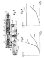
- Figure 6 shows a known preferred embodiment of valve 22, which comprises a body 24 defining, in addition to port 23, an inlet/outlet port 25 connected to pipe 17, and an inner cavity 26.
- Cavity 26 connects ports 23, 25 and houses a movable shutter 27, which is acted on by a spring 29 to define a nonreturn valve allowing oil flow from port 25 to port 23 and into chamber 11 to raise arm 2, while preventing flow in the opposite direction.
- Oil can flow from port 23 to port 25 through a passage 30, whose section (zero in Figure 6) is regulated by a shuttle 31 acted on oppositely by a preloaded spring 32 and by a hydraulic drive signal (indicated “Pil” along the x-axis in the Figure 4 graph) supplied by a control line 19 ( Figure 2) to an inlet 28 formed in body 24.
- a hydraulic drive signal indicated “Pil” along the x-axis in the Figure 4 graph
- shuttle 31 separates two chambers 33, 34; chamber 33 houses spring 32 and communicates with the tank in a manner not shown; and chamber 34 communicates with inlet 28, in a manner not shown, so that, as the drive signal increases, shuttle 31 slides to compress spring 32 and gradually increase the section of passage 30.
- the Figure 4 graph shows a curve A1 indicating the section of passage 30 as a function of the drive signal, indicated “Pil” along the x-axis; and a curve A2 indicating the flow section of valve 16, as a function of the drive signal, for the fluid drained by pipe 17 to line 5.
- the flow section of valve 16 from pipe 17 to line 5 is constant and greater than the section of passage 30 throughout the shift movement of valve 16 to lower arm 2, and for each value of the drive signal controlling both valves 16, 22 to lower arm 2, so that discharge from chamber 11, and therefore lowering of arm 2, is controlled solely by valve 22.
- valves B and C are controlled by a drive signal (indicated “Pil” along the x-axis), and have respective drain sections indicated by respective curves A3 and A4, which both vary as a function of the drive signal (Pil) and intersect each other, so that, in the known art, both valves B and C take part in controlling the oil flow drained to lower the operating arm.
- curve A4 is less than curve A3, so that lowering is substantially controlled by valve C as required by ISO standard 8643 governing the safe lowering speed of the operating arm, e.g. in the event of damage to the piping.
- curve A4 is greater than curve A3, so that lowering is substantially controlled by valve B.
- valve 22 oil flow from chamber 11 is regulated solely by valve 22, while valve 16 is so designed and/or driven as to have no control over oil flow from chamber 11.
- valve 16 therefore has practically no effect on the response times of valve 22, so that system 3 can be set to normal operation of arm 2 fairly easily, without flow control when lowering arm 2 being affected during transient operating states by the presence of two series valves.
- valve 22 in addition to regulating flow from chamber 11, valve 22 also performs a safety function, by being located adjacent to actuator 6 and promptly disabling lowering of arm 2, particularly in the event of damage to pipe 17.
- port 13 can be closed by valve 22 to prevent oil discharge from chamber 11. This is particularly useful in emergency situations involving damage to pipe 17, in which case, valve 22 is controlled to immediately prevent oil discharge from chamber 11, and also to control lowering of arm 2 to the ground.
- valve 16 may be replaced with two separate, independently controlled valves : one a proportional valve for regulating oil flow to and from chamber 12; and the other for proportionally regulating oil flow to chamber 11, and continuously connecting pipe 17 to line 5.
Abstract
Description
- The present invention relates to an earthmoving vehicle, in particular of the type comprising a supporting frame, and an operating arm fitted on the end with an excavating member, e.g. a shovel or bucket, and connected to the frame to move up and down under the control of a number of double-acting linear actuators.
- The actuators are controlled by a hydraulic central feed and control unit comprising, for each actuator, a proportional distributor valve, which is connected by pipes to the actuator chambers and, in use, regulates oil pressure and flow to and from the chambers.
- At times, vehicle buyers also require that the operating arm be used for moving loads, so an optional safety valve must be provided in series between each actuator and the relative distributor valve to safeguard promptly against oil discharge in the event of damage to the pipes or other intermediate elements, and so prevent dropping of the load caused by the operating arm dropping sharply.
- Addition of the safety valve, however, which is compulsory for this type of application, affects normal arm operation response times - which are calculated and set solely with reference to the proportional distributor valve - due to the two valves operating in contrast with each other in transient operating conditions.
- It is an object of the present invention to provide an earthmoving vehicle designed to provide a straightforward, low-cost solution to the above problem.
- According to the present invention, there is provided an earthmoving vehicle comprising an operating arm movable between a raised position and a lowered position, and a fluid system for moving said operating arm between said raised position and said lowered position; the system comprising a drain line for draining said fluid, at least one actuator connected to said operating arm and defining a variable-volume first chamber connectable to said drain line to lower said operating arm, and first and second proportional control means interposed between said drain line and said first chamber, and each performing a relative first shift movement associated with lowering of said operating arm to drain said fluid from said first chamber; said second control means being located in series between said first control means and said first chamber; characterized in that said first control means are so formed that said first shift movement permits free flow of said fluid to said drain line.
- The present invention also relates to a method of regulating lowering of an operating arm of an earthmoving vehicle.
- According to the present invention, there is provided a method of regulating lowering of an operating arm of an earthmoving vehicle comprising a fluid system for moving said operating arm between a raised position and a lowered position; the system comprising a drain line for draining said fluid, at least one actuator connected to said operating arm and defining a variable-volume chamber connectable to said drain line to lower said operating arm, and first and second proportional control means interposed between said drain line and said chamber; said second control means being located in series between said first control means and said chamber; the method comprising the steps of driving said first and second control means, and being characterized in that said first control means are driven to allow free flow of said fluid to said drain line when lowering said operating arm, so that lowering is controlled solely by said second control means.
- A non-limiting embodiment of the invention will be described by way of example with reference to the accompanying drawings, in which:
- Figure 1 shows a preferred, non-limiting embodiment of the earthmoving vehicle according to the present invention;
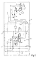
- Figure 2 shows a partial diagram of a hydraulic system of the Figure 1 vehicle;
- Figure 3 is similar to Figure 2 and shows a hydraulic system of a known earthmoving vehicle;
- Figure 4 shows a graph of an operating characteristic of the Figure 2 hydraulic system;
- Figure 5 is similar to Figure 4 and shows an operating characteristic of the Figure 3, i.e. known, hydraulic system;
- Figure 6 shows a cross section of a valve of the Figure 2 hydraulic system.
-
-
Number 1 in Figure 1 indicates an earthmoving vehicle comprising a supportingframe 1a, and anoperating arm 2, which is fitted at one end with a gripping or excavatingmember 2a (e.g. a shovel or bucket), is articulated, and is connected toframe 1a to move up/down between a first operating position (not shown) in which the end is raised, and a second operating position in which the end is lowered. - With reference to Figure 2,
vehicle 1 also comprises a hydraulic system 3 (shown partly and schematically) in turn comprising an oil feed line 4 communicating with a hydraulic pump (not shown), adrain line 5 connected to a tank (not shown), and a number of linearhydraulic actuators 6 or jacks connected toarm 2 in known manner to raise and lowerarm 2 between said first and said second operating position. - In Figure 2, only the part of
system 3 relating to one ofactuators 6 is shown, the same configuration substantially also applying to theother actuators 6. -
Actuator 6 is a double-acting type and comprises ahousing 7; and apiston 9, which is connected integrally to arod 10, is movable insidehousing 7 to moverod 10 between a withdrawn position and an extracted position with respect tohousing 7, and separates two variable-volume chambers outlet ports 13, 14 formed inhousing 7 to receive pressurized oil from line 4 to raise andlower arm 2 respectively. - With reference to Figure 2,
system 3 comprises a hydrauliccentral control unit 15 at a distance fromarm 2 and in turn comprising, for eachactuator 6, arelative distributor valve 16 connected toports 13, 14 byrespective pipes - Valve 16 is driven by two
control lines arm 2. Valve 16 regulates oil flow to and fromchamber 12 continuously, and selectively connectschamber 11 to line 4 when raisingarm 2, or directly todrain line 5, both when idle (in the center position) and when shifted to lowerarm 2. In other words, the construction characteristics and response times ofvalve 16 are such that it acts as a proportional or continuous-position valve with regard to oil flow to and fromchamber 12 and tochamber 11, while allowing free passage, i.e. effecting no control of, oil flow fromchamber 11 when shifted tolower arm 2. - With reference to Figures 2 and 4, when so shifted from the center position,
valve 16 has a constant flow section for the fluid drained fromchamber 11 alongpipe 17, and oil flow fromchamber 11 is regulated continuously by a proportional or continuous-position shuttle orslide regulating valve 22. - Valve 22 forms part of
system 3 and is located in series withvalve 16, at the end ofpipe 17 and adjacent tochamber 11, i.e. in such a position as to dispense with ordinary connecting pipes, subject to damage, betweenactuator 6 andvalve 22. Preferably,valve 22 is located with an inlet/outlet port 23 connected directly tohousing 7 and, therefore, coincident with port 13. - Figure 6 shows a known preferred embodiment of
valve 22, which comprises abody 24 defining, in addition toport 23, an inlet/outlet port 25 connected topipe 17, and aninner cavity 26.Cavity 26 connectsports movable shutter 27, which is acted on by aspring 29 to define a nonreturn valve allowing oil flow fromport 25 toport 23 and intochamber 11 to raisearm 2, while preventing flow in the opposite direction. - Oil can flow from
port 23 toport 25 through apassage 30, whose section (zero in Figure 6) is regulated by ashuttle 31 acted on oppositely by a preloadedspring 32 and by a hydraulic drive signal (indicated "Pil" along the x-axis in the Figure 4 graph) supplied by a control line 19 (Figure 2) to aninlet 28 formed inbody 24. - More specifically,
shuttle 31 separates twochambers chamber 33houses spring 32 and communicates with the tank in a manner not shown; andchamber 34 communicates withinlet 28, in a manner not shown, so that, as the drive signal increases,shuttle 31 slides to compressspring 32 and gradually increase the section ofpassage 30. - The Figure 4 graph shows a curve A1 indicating the section of
passage 30 as a function of the drive signal, indicated "Pil" along the x-axis; and a curve A2 indicating the flow section ofvalve 16, as a function of the drive signal, for the fluid drained bypipe 17 toline 5. The flow section ofvalve 16 frompipe 17 toline 5 is constant and greater than the section ofpassage 30 throughout the shift movement ofvalve 16 tolower arm 2, and for each value of the drive signal controlling bothvalves lower arm 2, so that discharge fromchamber 11, and therefore lowering ofarm 2, is controlled solely byvalve 22. - In the known art, on the other hand, as shown in Figure 3, lowering of the operating arm of the vehicle is regulated by a distributor valve B and a safety valve C (not shown in detail), which are located in series between drain line D and actuator E, and operate as shown in the Figure 5 graph. That is, when lowering the operating arm, valves B and C are controlled by a drive signal (indicated "Pil" along the x-axis), and have respective drain sections indicated by respective curves A3 and A4, which both vary as a function of the drive signal (Pil) and intersect each other, so that, in the known art, both valves B and C take part in controlling the oil flow drained to lower the operating arm. More specifically, along a first regulating portion, curve A4 is less than curve A3, so that lowering is substantially controlled by valve C as required by ISO standard 8643 governing the safe lowering speed of the operating arm, e.g. in the event of damage to the piping. Along a second regulating portion, on the other hand, curve A4 is greater than curve A3, so that lowering is substantially controlled by valve B.
- As will be clear from the above description, oil flow from
chamber 11 is regulated solely byvalve 22, whilevalve 16 is so designed and/or driven as to have no control over oil flow fromchamber 11. - Activation of
valve 16 therefore has practically no effect on the response times ofvalve 22, so thatsystem 3 can be set to normal operation ofarm 2 fairly easily, without flow control when loweringarm 2 being affected during transient operating states by the presence of two series valves. - Moreover, in addition to regulating flow from
chamber 11,valve 22 also performs a safety function, by being located adjacent toactuator 6 and promptly disabling lowering ofarm 2, particularly in the event of damage topipe 17. - That is, as shown in Figure 2, in actual use, to prevent lowering
arm 2 and dropping any loads onarm 2, port 13 can be closed byvalve 22 to prevent oil discharge fromchamber 11. This is particularly useful in emergency situations involving damage topipe 17, in which case,valve 22 is controlled to immediately prevent oil discharge fromchamber 11, and also to control lowering ofarm 2 to the ground. - Clearly, changes may be made to
vehicle 1 as described and illustrated herein without, however, departing from the scope of the present invention. - In particular,
valve 16 may be replaced with two separate, independently controlled valves : one a proportional valve for regulating oil flow to and fromchamber 12; and the other for proportionally regulating oil flow tochamber 11, and continuously connectingpipe 17 toline 5.
Claims (9)
- An earthmoving vehicle (1) comprising an operating arm (2) movable between a raised position and a lowered position, and a fluid system (3) for moving said operating (2) arm between said raised position and said lowered position; the system comprising a drain line (5) for draining said fluid, at least one actuator (6) connected to said operating arm (2) and defining a variable-volume first chamber (11) connectable to said drain line (5) to lower said operating arm (2), and first and second proportional control means (16)(22) interposed between said drain line (5) and said first chamber (11), and each performing a relative first shift movement, associated with lowering of said operating arm (2), to drain said fluid from said first chamber (11); said second control means (22) being located in series between said first control means (16) and said first chamber (11); characterized in that said first control means (16) are so formed that said first shift movement permits free flow of said fluid to said drain line (5).
- A vehicle as claimed in Claim 1, characterized in that said first and second control means (16)(22) are controlled by a drive signal (Pil) so as each to perform the relative said first shift movement; said first control means (16) having a flow section (A2) to said drain line (5) greater than that (A1) of said second control means (22) for each value of said drive signal (Pil).
- A vehicle as claimed in Claim 2, characterized in that, at said first shift movement, the flow section (A2) of said first control means (16) is constant for each value of said drive signal (Pil).
- A vehicle as claimed in any one of the foregoing Claims, characterized in that said first control means (16) comprise a regulating valve (16) performing said first shift movement and a second shift movement to proportionally regulate fluid flow to said first chamber (11).
- A vehicle as claimed in Claim 4, characterized in that said actuator (6) defines a variable-volume second chamber (12); said regulating valve forming part of a distributor valve (16) for proportionally regulating fluid flow to and from said second chamber (12).
- A vehicle as claimed in any one of the foregoing Claims, characterized in that said second control means comprise a proportional valve (22) having an inlet/outlet port coincident with a port (13) of said first chamber (11).
- A method of regulating lowering of an operating arm of an earthmoving vehicle (1) comprising a fluid system (3) for moving said operating arm (2) between a raised position and a lowered position; the system comprising a drain line (5) for draining said fluid, at least one actuator (6) connected to said operating arm (2) and defining a variable-volume chamber (11) connectable to said drain line (5) to lower said operating arm (2), and first and second proportional control means (16)(22) interposed between said drain line (5) and said chamber (11); said second control means (22) being located in series between said first control means (16) and said chamber (11); the method comprising the steps of driving said first and second control means (16) (22), and being characterized in that said first control means (16) are driven to allow free flow of said fluid to said drain line (5) when lowering said operating arm (2), so that lowering is controlled solely by said second control means (22).
- An earthmoving vehicle, substantially as described and illustrated in the accompanying drawings.
- A method of regulating lowering of an operating arm of an earthmoving vehicle, substantially as described with reference to the accompanying drawings.
Applications Claiming Priority (2)
| Application Number | Priority Date | Filing Date | Title |
|---|---|---|---|
| ITTO20020186 | 2002-03-06 | ||
| IT2002TO000186A ITTO20020186A1 (en) | 2002-03-06 | 2002-03-06 | EARTH-MOVING VEHICLE, AND METHOD TO ADJUST THE DESCENT OF AN OPERATING ARM OF SUCH VEHICLE. |
Publications (2)
| Publication Number | Publication Date |
|---|---|
| EP1347103A2 true EP1347103A2 (en) | 2003-09-24 |
| EP1347103A3 EP1347103A3 (en) | 2004-01-07 |
Family
ID=27638888
Family Applications (1)
| Application Number | Title | Priority Date | Filing Date |
|---|---|---|---|
| EP03075645A Withdrawn EP1347103A3 (en) | 2002-03-06 | 2003-03-05 | Control of an operating arm of an earthmoving vehicle |
Country Status (3)
| Country | Link |
|---|---|
| US (1) | US7076896B2 (en) |
| EP (1) | EP1347103A3 (en) |
| IT (1) | ITTO20020186A1 (en) |
Cited By (1)
| Publication number | Priority date | Publication date | Assignee | Title |
|---|---|---|---|---|
| US7076896B2 (en) | 2002-03-06 | 2006-07-18 | Cnh America Llc | Control for an operating arm of an earthmoving vehicle |
Families Citing this family (3)
| Publication number | Priority date | Publication date | Assignee | Title |
|---|---|---|---|---|
| DE102005021887A1 (en) * | 2005-05-04 | 2006-11-16 | Kässbohrer Geländefahrzeug AG | Method and device for driving stability increase of motor vehicles |
| DE202009006299U1 (en) * | 2009-04-29 | 2010-09-09 | Liebherr-France Sas, Colmar | Hydraulic system as well as mobile construction machine |
| EP3861175B1 (en) | 2018-10-02 | 2022-09-14 | Clark Equipment Company | Distributed hydraulic system |
Citations (2)
| Publication number | Priority date | Publication date | Assignee | Title |
|---|---|---|---|---|
| FR2328868A1 (en) * | 1975-10-21 | 1977-05-20 | Monsun Tison Ab | Hydraulic motor line leakage controller - has nonreturn valve in parallel with variable choke valve |
| US20010046433A1 (en) * | 2000-05-26 | 2001-11-29 | Satoru Nishimura | Hydraulic shovel with hoisting hook |
Family Cites Families (20)
| Publication number | Priority date | Publication date | Assignee | Title |
|---|---|---|---|---|
| FR2487019A2 (en) * | 1980-03-25 | 1982-01-22 | Richier Nle Indle | Pressure controlled safety device for hydraulic lifting device - uses electromagnetically operated control valve in non-return valve to hold pressure while load is being lowered |
| SE459270B (en) * | 1985-02-26 | 1989-06-19 | Bahco Hydrauto Ab | VALVE ARRANGEMENTS FOR CONTROL OF PRESSURE FLUID THROUGH A PRESSURE CIRCUIT |
| JPH0288825A (en) * | 1988-09-26 | 1990-03-29 | Yutani Heavy Ind Ltd | Hydraulic circuit of construction machinery |
| KR0149708B1 (en) * | 1994-07-25 | 1998-10-15 | 석진철 | Apparatus of controlling rotating torque |
| KR970011608B1 (en) * | 1994-09-06 | 1997-07-12 | 대우중공업 주식회사 | Apparatus for controlling tunning torque in a construction equipment |
| JPH08268088A (en) | 1995-03-31 | 1996-10-15 | Hitachi Constr Mach Co Ltd | Cooling structure of construction equipment |
| JP3153096B2 (en) * | 1995-04-27 | 2001-04-03 | 株式会社クボタ | Lawn mower lifting valve structure |
| EP0862698B1 (en) * | 1995-12-15 | 2003-03-05 | Parker Hannifin Plc | Control valves |
| US6050090A (en) * | 1996-06-11 | 2000-04-18 | Kabushiki Kaisha Kobe Seiko Sho | Control apparatus for hydraulic excavator |
| JPH11181843A (en) * | 1997-12-17 | 1999-07-06 | Komatsu Ltd | Wheel loader |
| JP2000045339A (en) * | 1998-07-29 | 2000-02-15 | Yutani Heavy Ind Ltd | Hydraulic controller |
| JP3919399B2 (en) * | 1998-11-25 | 2007-05-23 | カヤバ工業株式会社 | Hydraulic control circuit |
| JP2001040713A (en) * | 1999-08-03 | 2001-02-13 | Shin Caterpillar Mitsubishi Ltd | Construction machine with crane function |
| US6282890B1 (en) * | 2000-01-21 | 2001-09-04 | Komatsu Ltd. | Hydraulic circuit for construction machines |
| JP2001263305A (en) * | 2000-03-17 | 2001-09-26 | Shin Caterpillar Mitsubishi Ltd | Hydraulic circuit |
| JP3727828B2 (en) * | 2000-05-19 | 2005-12-21 | 日立建機株式会社 | Pipe break control valve device |
| JP2001342648A (en) * | 2000-06-02 | 2001-12-14 | Komatsu Ltd | Hydraulic backhoe |
| JP2002294757A (en) * | 2001-03-28 | 2002-10-09 | Kubota Corp | Backhoe |
| ITBO20010365A1 (en) | 2001-06-08 | 2002-12-08 | New Holland Italia Spa | EARTH-MOVING MACHINE AND ACTUATOR DEVICE FOR THE SIDE MOVEMENT OF A RELATIVE LOADER LOADER |
| ITTO20020186A1 (en) | 2002-03-06 | 2003-09-08 | Fiat Hitachi Excavators S P A | EARTH-MOVING VEHICLE, AND METHOD TO ADJUST THE DESCENT OF AN OPERATING ARM OF SUCH VEHICLE. |
-
2002
- 2002-03-06 IT IT2002TO000186A patent/ITTO20020186A1/en unknown
-
2003
- 2003-03-05 EP EP03075645A patent/EP1347103A3/en not_active Withdrawn
- 2003-03-06 US US10/384,316 patent/US7076896B2/en not_active Expired - Lifetime
Patent Citations (2)
| Publication number | Priority date | Publication date | Assignee | Title |
|---|---|---|---|---|
| FR2328868A1 (en) * | 1975-10-21 | 1977-05-20 | Monsun Tison Ab | Hydraulic motor line leakage controller - has nonreturn valve in parallel with variable choke valve |
| US20010046433A1 (en) * | 2000-05-26 | 2001-11-29 | Satoru Nishimura | Hydraulic shovel with hoisting hook |
Cited By (1)
| Publication number | Priority date | Publication date | Assignee | Title |
|---|---|---|---|---|
| US7076896B2 (en) | 2002-03-06 | 2006-07-18 | Cnh America Llc | Control for an operating arm of an earthmoving vehicle |
Also Published As
| Publication number | Publication date |
|---|---|
| US7076896B2 (en) | 2006-07-18 |
| EP1347103A3 (en) | 2004-01-07 |
| ITTO20020186A1 (en) | 2003-09-08 |
| ITTO20020186A0 (en) | 2002-03-06 |
| US20040153230A1 (en) | 2004-08-05 |
Similar Documents
| Publication | Publication Date | Title |
|---|---|---|
| US7243591B2 (en) | Hydraulic valve arrangement | |
| JP4791789B2 (en) | Electronically operated and hydraulically operated drain valve | |
| JP4870366B2 (en) | Closed circuit energy recovery system for work implements | |
| CN203743137U (en) | Measurement-free hydraulic system with load keeping bypass | |
| US7353744B2 (en) | Hydraulic control | |
| EP2857695B1 (en) | Boom drive device for construction machine | |
| JP2634321B2 (en) | Cargo handling machinery | |
| US8899143B2 (en) | Hydraulic control system having variable pressure relief | |
| AU2007249080B2 (en) | Hydraulic valve arrangement | |
| US8944103B2 (en) | Meterless hydraulic system having displacement control valve | |
| US20030041728A1 (en) | Control for electro-hydraulic valve arrangement | |
| RU2571068C2 (en) | Valve system | |
| US9683587B2 (en) | Fluid pressure control device | |
| US5447094A (en) | Hydraulic system for bucket self-leveling during raising and lowering of boom | |
| CN110023632B (en) | Hydraulic system | |
| JP2013508647A (en) | Safety mechanism for valve sticking | |
| EP3311034B1 (en) | Load sensing hydraulic system for a working machine | |
| US8966892B2 (en) | Meterless hydraulic system having restricted primary makeup | |
| KR20170136613A (en) | Method for controlling load sensing hydraulic system and load sensing hydraulic system for working machine | |
| EP2672022B1 (en) | Hydarulic fluid control system for a work vehicle | |
| EP1347103A2 (en) | Control of an operating arm of an earthmoving vehicle | |
| KR102518559B1 (en) | Valve arrangement for stem cylinder with two operating conditions | |
| JP6615137B2 (en) | Hydraulic drive unit for construction machinery | |
| JP7161465B2 (en) | Hydraulic circuit for construction machinery | |
| RU2209540C2 (en) | Grain combine hydraulic system |
Legal Events
| Date | Code | Title | Description |
|---|---|---|---|
| PUAI | Public reference made under article 153(3) epc to a published international application that has entered the european phase |
Free format text: ORIGINAL CODE: 0009012 |
|
| AK | Designated contracting states |
Kind code of ref document: A2 Designated state(s): AT BE BG CH CY CZ DE DK EE ES FI FR GB GR HU IE IT LI LU MC NL PT RO SE SI SK TR |
|
| AX | Request for extension of the european patent |
Extension state: AL LT LV MK |
|
| PUAL | Search report despatched |
Free format text: ORIGINAL CODE: 0009013 |
|
| AK | Designated contracting states |
Kind code of ref document: A3 Designated state(s): AT BE BG CH CY CZ DE DK EE ES FI FR GB GR HU IE IT LI LU MC NL PT RO SE SI SK TR |
|
| AX | Request for extension of the european patent |
Extension state: AL LT LV MK |
|
| 17P | Request for examination filed |
Effective date: 20040705 |
|
| AKX | Designation fees paid |
Designated state(s): AT BE BG CH CY CZ DE DK EE ES FI FR GB GR HU IE IT LI LU MC NL PT RO SE SI SK TR |
|
| 17Q | First examination report despatched |
Effective date: 20091019 |
|
| STAA | Information on the status of an ep patent application or granted ep patent |
Free format text: STATUS: THE APPLICATION IS DEEMED TO BE WITHDRAWN |
|
| 18D | Application deemed to be withdrawn |
Effective date: 20100504 |