EP1346384B1 - Gesicherte tastatur - Google Patents
Gesicherte tastatur Download PDFInfo
- Publication number
- EP1346384B1 EP1346384B1 EP01982523A EP01982523A EP1346384B1 EP 1346384 B1 EP1346384 B1 EP 1346384B1 EP 01982523 A EP01982523 A EP 01982523A EP 01982523 A EP01982523 A EP 01982523A EP 1346384 B1 EP1346384 B1 EP 1346384B1
- Authority
- EP
- European Patent Office
- Prior art keywords
- keyboard
- conductive portion
- membrane
- contacts
- electronic
- Prior art date
- Legal status (The legal status is an assumption and is not a legal conclusion. Google has not performed a legal analysis and makes no representation as to the accuracy of the status listed.)
- Expired - Lifetime
Links
Images
Classifications
-
- G—PHYSICS
- G06—COMPUTING; CALCULATING OR COUNTING
- G06F—ELECTRIC DIGITAL DATA PROCESSING
- G06F21/00—Security arrangements for protecting computers, components thereof, programs or data against unauthorised activity
- G06F21/70—Protecting specific internal or peripheral components, in which the protection of a component leads to protection of the entire computer
- G06F21/82—Protecting input, output or interconnection devices
- G06F21/83—Protecting input, output or interconnection devices input devices, e.g. keyboards, mice or controllers thereof
-
- H—ELECTRICITY
- H01—ELECTRIC ELEMENTS
- H01H—ELECTRIC SWITCHES; RELAYS; SELECTORS; EMERGENCY PROTECTIVE DEVICES
- H01H2239/00—Miscellaneous
- H01H2239/032—Anti-tamper
Definitions
- the present invention relates to protection against intrusions of electronic devices containing a keyboard for entering confidential data. It is particularly suitable for banking terminals, mobile phones, computers, etc.
- FIG. 1 A solution of the prior art is shown in Figure 1.
- the keyboard function is performed by a silicone membrane 1 combined with an electronic card 2.
- This membrane 1 is held in compression between the electronic card 2 screwed by screws 8 in the cover 3 of the electronic device.
- the membrane contains elastic blisters 4 serving as keyboard keys.
- Each key 4 passes through the cover 3 through an opening 16 of the latter to be accessible from the outside.
- Each blister comprises at its base a conductive portion 5 generally made of silicone loaded with carbon.
- the conductive parts 5 face contacts 6 of the "comb" type, placed on the electronic card 2 and composed of two separate and interleaved electrical circuits, respectively connected to two separate terminals of a microprocessor 7.
- a type of fraud consists of placing additional electrical circuits between the conductive parts 5 and the contacts 6 in order to detect the keys pressed and enter the confidential data at the expense of the user. For this, it is necessary to intervene between the card 2 and the cover 3.
- a solution of the prior art to avoid this type of fraud is to add a commercial switch 9 trade on the electronic card 2, maintained in compression between the card 2 and the cover 3.
- the switch 9 and the contacts 6 of the electronic card 2 communicate with the microprocessor 7. These communications are symbolized by links 13.
- a separation of the card 2 of the cover 3 is detected by the switch 9 which informs the microprocessor of the forbidden intrusion; automatic anti-fraud measures are then deployed, such as, for example, putting the device to sleep, deleting confidential data, etc.
- An object of the present invention is to provide a less expensive alternative solution, easier to achieve and more flexible.
- the present invention provides a keyboard security device, comprising keys and an electronic card forming a keyboard and linked to a cover of an electronic device, at least one dedicated key of the keyboard being kept pressed in a first state normal operation of the apparatus for closing an electrical intrusion detection circuit on the electronic board, an opening of the keyboard being detected by an opening of said circuit, caused by the release of said dedicated key.
- said dedicated key carries at least one conductive portion facing at least one contact of the electronic card closing, in normal operating position, said intrusion detection circuit.
- the invention also provides a security device for a membrane keyboard, comprising at least one membrane and an electronic card forming a keyboard and linked to a cover of an electronic device, at least one membrane containing a conductive part in viewing at least one contact on the electronic card so as to detect a relative movement of the contact and the conductive portion.
- the conductive portion and the contact close an electrical circuit in the normal operating position of the keyboard, the relative movement being detected by an opening of the electrical circuit.
- the membrane contains at least one pin having at its base the conductive portion.
- the conductive portion is gilded.
- the conductive portion is intended to electrically connect two contacts of the electronic card, the contacts being, preferably, contacts of the "comb" type.
- the invention also relates to a payment terminal having such a security device.
- the invention also relates to a telephone device having such a security device.
- the invention further relates to a computer having such a security device.
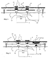
- Figure 2 shows a first embodiment of the invention. This embodiment applies, for example, to a computer keyboard type keyboard or the like.
- a cover 3 of an apparatus has openings 16 to reveal piston keys 4 of a keyboard.
- These keys comprise a conductive part 5 at their base opposite contacts 6 on an electronic card 2.
- a pressure on the top of a key 4 makes it possible to create an electrical connection between the conductive part 5 and the contacts 6, which closes an electrical circuit 13 on the electronic card.
- a return spring 14 then returns the key 4 to its rest position (raised) as shown in FIG.
- At least one key 4 ' is placed under the cover 3 of the electronic device, that is to say without being associated with an opening 16.
- the key 4' is, for example, housed in a niche 15 formed on the internal face of the cover 3.
- the key 4 ' is maintained in permanent pressure so as to provide an electrical connection between its conductive portion 5' and two contacts 6 'underlying formed on the electronic card 2.
- the contacts 6 represent the ends of an electrical intrusion detection circuit 12 passing, for example, by a microprocessor 7 and which is closed by the part 5 '.
- a separation of the electronic card 2 of the cover 3 will cause an opening of this circuit 12, which will for example be detected by the microprocessor 7.
- at least one additional keyboard key is provided and no provision is made for opening facing the hood. This provides a permanently depressed key that does not rise, to open the detection circuit 12, in case of intrusion.
- a first advantage of such an embodiment is to simplify the device of the prior art. It is sufficient to provide additional contacts 6 'on the electronic card 2 and corresponding keyboard keys. The manufacture of such a device is much simpler. In particular, the need to solder a specific component is eliminated.
- a second advantage is the low cost of the security device according to the invention. Indeed, the addition of some keyboard keys and some contacts on the electronic card leads to a small additional cost because it is the usual elements of the keyboard.
- the security device of the invention that applies to an electronic keyboard device consists in giving some of the keys of the keyboard an intrusion detection function whereas, on the contrary, the prior art directs the skilled person to add a specific autonomous element.
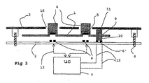
- Figure 3 shows a second preferred embodiment of the present invention, more particularly for a membrane keypad.
- the electrical apparatus contains a membrane keyboard device composed of a membrane 1 and an electronic card 2, operating according to the principle of the prior art represented by FIG. 1 and previously described.
- the membrane 1 contains at least one pin 11 of silicone, whose base contains a conductive portion 10 in permanent electrical connection with contacts 6 'facing the electronic card 2.
- contacts 6' of type "comb" identical to those 6 used for the keyboard function.
- This permanent electrical connection creates a closed electrical loop 12 on the electronic card 2 whose ends are connected, for example, to the microprocessor 7.
- the dimensions of the pin 11 are fixed so as to ensure a sufficient pressure between the contacts 6 'and. the conductive portion 10, to provide the electrical connection.
- This pressure is also advantageously increased to be able to withstand certain shocks such as the fall of the device, its involuntary torsion, etc. For example, it is measured that a pressure of the order of 250 g is sufficient for a conventional terminal payment type device. This value can be reduced in the case of a more compact device and less subject to twisting, for example.
- a separation of the electronic card 2 of the cover 3 will reduce the pressure between the contacts 6 'and the conductive portion 10 until a break in the electrical connection, causing the opening of the loop 12. This opening will be detected by the microprocessor 7.
- This new device thus fulfills simply a switch function taking advantage of the elasticity of the membrane 1 and advantageously adding a conductive portion 10.
- the two essential elements of the safety device according to this second embodiment of the invention are therefore on the one hand to less a conductive portion 10 connected to a membrane 1 and secondly the electronic card 2 having at least one contact 6 opposite, the two elements 10 and 6 'for making a safety switch.
- An advantage of this second embodiment in addition to its simplicity and low cost, is that it requires no additional element, the electronic card 2 and the membrane 1 sufficient to provide the safety function. In particular, it saves the use of a spring switch of a conventional secure keyboard.
- the function of the pin 11 which is to ensure the pressure between the contacts 6 'and the conductive portion 10 after mounting the three elements that are the cover, the membrane and the electronic card, can be filled by a protuberance at the level of the cover 3 or on the card 2, the conductive part 10 always being connected to the membrane 1.
- the contacts 6 and the conductive portion 10 of the device according to the invention can be of any type; it is sufficient that they provide a permanent electrical connection in the normal operating position of the appliance.
- a single contact 6 'and a single conductive portion 10 may suffice if the electric detection circuit is also permanently closed, for example, by a wire conductor connecting the keyboard to the card.
- the electric circuit closed by the security device of the invention comprises two keys or the like of the keyboard. Each key is associated with a single contact 6 'of the card and the two parts conductive conductors 10 are electrically connected by a conductive ink circuit on the membrane for example.
- the device according to the present invention offers great flexibility since it is possible to accumulate easily several of these safety devices, which can be connected in series or in parallel between the same terminals of the microprocessor 7, or on different terminals. Among the many possible combinations, one will choose the one that corresponds to the level of security sought. It is also possible to do without a microprocessor by using for example the device directly as a circuit breaker of the power supply of the device.
Claims (10)
- Sicherheitsvorrichtung für eine Tastatur, mit Tasten (4) und eine Leiterplatte (2), die die Tastatur bilden und mit einer Haube (3) eines elektronischen Geräts verbunden sind, dadurch gekennzeichnet, dass wenigstens eine dezidierte Taste (4') der Tastatur in einem ersten, normalen Funktionszustand des Geräts gedrückt gehalten wird, um einen elektrischen Schaltkreis (12) für die lnstruktionsdetektion auf der Leiterplatte (2) zu schließen, wobei eine Öffnung der Tastatur durch eine Öffnung des besagten Schaltkreises detektiert wird, die durch die Freigabe der besagten dezidierten Taste ausgelöst wird
- Sicherheitsvorrichtung für eine Membran-Tastatur mit wenigstens einer Membran (1) und einer Leiterplatte (2), die die Tastatur bilden und an einer Haube (3) eines elektrischen Geräts befestigt sind, dadurch gekennzeichnet, dass wenigstens eine Membran (1) einen leitenden Bereich (10) bezüglich wenigstens einem Kontakt (6') auf der Leiterplatte (2) aufweist, um einen relativen Versatz des Kontakts (6') und des leitenden Bereichs (10) zu detektieren.
- Vorrichtung nach Anspruch 2, dadurch gekennzeichnet, dass der leitende Bereich (10) und der Kontakt (6') einen elektrischen Schaltkreis (12) in normaler Position der Funktion der Tastatur schließen, wobei der relative Versatz durch eine Öffnung des elektronischen Schaltkreis (12) festgestellt wird
- Vorrichtung nach Anspruch 2 oder 3, dadurch gekennzeichnet, dass die Membran (1) wenigstens eine Nadel (11) aufweist, die an seiner Unterseite den leitenden Bereich (10) besitzt
- Vorrichtung nach Anspruch 1, dadurch gekennzeichnet, dass die besagte dezidierte Taste (4') wenigstens einen leitenden Bereich (5') bezüglich wenigstens einem Kontakt (6') der elektronischen Leiterplatte (2) trägt, die in normaler Funktionsposition den besagten Schaltkreis (12) zur Detektion der Instruktion schließt.
- Vorrichtung nach einem der Ansprüchen 2 bis 5, dadurch gekennzeichnet, dass der leitende Bereich (5', 10) vergoldet ist.
- Vorrichtung nach einem der Ansprüchen 2 bis 6, dadurch gekennzeichnet, dass der leitende Bereich (5', 10) dazu bestimmt ist, zwei Kontakte (6') der Leiterplatte elektrisch zu verbinden, wobei die Kontakte (6') vorzugsweise Kontakte des Typs "Kamm" bzw. "peigne" sind.
- Zahlungsterminal mit einer Sicherheitsvorrichtung gemäß einem der vorhergehenden Ansprüche.
- Telefonapparat mit einer Sicherheitsvorrichtung gemäß einem der vorhergehenden Ansprüche
- Rechner mit einer Sicherheitsvorrichtung gemäß einem der vorhergehenden Ansprüche.
Applications Claiming Priority (3)
| Application Number | Priority Date | Filing Date | Title |
|---|---|---|---|
| FR0013463 | 2000-10-20 | ||
| FR0013463A FR2815733B1 (fr) | 2000-10-20 | 2000-10-20 | Clavier securise |
| PCT/FR2001/003259 WO2002033717A1 (fr) | 2000-10-20 | 2001-10-19 | Clavier securise |
Publications (2)
| Publication Number | Publication Date |
|---|---|
| EP1346384A1 EP1346384A1 (de) | 2003-09-24 |
| EP1346384B1 true EP1346384B1 (de) | 2006-12-13 |
Family
ID=8855560
Family Applications (1)
| Application Number | Title | Priority Date | Filing Date |
|---|---|---|---|
| EP01982523A Expired - Lifetime EP1346384B1 (de) | 2000-10-20 | 2001-10-19 | Gesicherte tastatur |
Country Status (5)
| Country | Link |
|---|---|
| EP (1) | EP1346384B1 (de) |
| AU (1) | AU2002214083A1 (de) |
| ES (1) | ES2278795T3 (de) |
| FR (1) | FR2815733B1 (de) |
| WO (1) | WO2002033717A1 (de) |
Cited By (4)
| Publication number | Priority date | Publication date | Assignee | Title |
|---|---|---|---|---|
| WO2009027472A1 (de) | 2007-08-28 | 2009-03-05 | Hypercom Gmbh | Sicherheitstastatur |
| DE102008003264A1 (de) * | 2008-01-04 | 2009-07-09 | Demmel Ag | Abgesicherte Tastatur mit Schutz gegen Ausbau der Tasten |
| DE102009054877A1 (de) | 2009-12-17 | 2011-06-22 | ZF Friedrichshafen AG, 88046 | Tastatur |
| FR3056370A1 (fr) * | 2016-09-22 | 2018-03-23 | Ingenico Group | Piece de support d'un composant d'un dispositif electronique securise |
Families Citing this family (8)
| Publication number | Priority date | Publication date | Assignee | Title |
|---|---|---|---|---|
| FR2860643B1 (fr) | 2003-10-07 | 2006-02-17 | Thales Sa | Dispositif anti-intrusion notamment pour terminal de paiement electronique |
| GB0504176D0 (en) * | 2005-03-01 | 2005-04-06 | Keymat Technology Ltd | Anti-tamper devices |
| US7388484B2 (en) * | 2005-08-16 | 2008-06-17 | Honeywell International Inc. | Conductive tamper switch for security devices |
| FR2897702B1 (fr) * | 2006-02-22 | 2008-04-25 | Sagem Monetel Soc Par Actions | Dispositif anti-intrusion |
| FR2901896B1 (fr) * | 2006-06-02 | 2008-10-31 | Sagem Monetel Soc Par Actions | Dispositif de protection contre les intrusions d'appareil electronique |
| FR2906623B1 (fr) | 2006-10-02 | 2009-01-16 | Sagem Monetel Soc Par Actions | Dispositif de protection pour carte electronique |
| FR2929042B1 (fr) * | 2008-03-21 | 2011-06-03 | Sagem Monetel | Dispositif de protection d'un systeme electronique |
| FR3036211B1 (fr) | 2015-05-11 | 2017-06-09 | Ingenico Group | Detection d'ouverture d'un dispositif de saisie de donnees |
Family Cites Families (2)
| Publication number | Priority date | Publication date | Assignee | Title |
|---|---|---|---|---|
| US4644326A (en) * | 1983-06-03 | 1987-02-17 | Secure Keyboards Limited | Unitary key panel |
| DE19600768C2 (de) * | 1996-01-11 | 1998-04-16 | Ibm | Sicherheitstastatur |
-
2000
- 2000-10-20 FR FR0013463A patent/FR2815733B1/fr not_active Expired - Fee Related
-
2001
- 2001-10-19 AU AU2002214083A patent/AU2002214083A1/en not_active Abandoned
- 2001-10-19 EP EP01982523A patent/EP1346384B1/de not_active Expired - Lifetime
- 2001-10-19 ES ES01982523T patent/ES2278795T3/es not_active Expired - Lifetime
- 2001-10-19 WO PCT/FR2001/003259 patent/WO2002033717A1/fr active IP Right Grant
Cited By (13)
| Publication number | Priority date | Publication date | Assignee | Title |
|---|---|---|---|---|
| EP2183729B1 (de) * | 2007-08-28 | 2016-11-02 | VeriFone GmbH | Sicherheitstastatur |
| DE102007040637A1 (de) * | 2007-08-28 | 2009-03-05 | Thales E-Transactions Gmbh | Sicherheitstastatur |
| DE102007040637B4 (de) * | 2007-08-28 | 2009-04-23 | Thales E-Transactions Gmbh | Sicherheitstastatur |
| DE102007040637B8 (de) * | 2007-08-28 | 2009-08-13 | Hypercom Gmbh | Sicherheitstastatur |
| EP2183729A1 (de) * | 2007-08-28 | 2010-05-12 | Hypercom GmbH | Sicherheitstastatur |
| WO2009027472A1 (de) | 2007-08-28 | 2009-03-05 | Hypercom Gmbh | Sicherheitstastatur |
| DE102008003264A1 (de) * | 2008-01-04 | 2009-07-09 | Demmel Ag | Abgesicherte Tastatur mit Schutz gegen Ausbau der Tasten |
| DE102008003264B4 (de) * | 2008-01-04 | 2016-07-28 | Demmel Ag | Manipulationsgeschütze Tastatur mit Schutz gegen Ausbau der Tastenkappen |
| DE102009054877A1 (de) | 2009-12-17 | 2011-06-22 | ZF Friedrichshafen AG, 88046 | Tastatur |
| DE102009054877B4 (de) | 2009-12-17 | 2018-06-28 | Cherry Gmbh | Tastatur |
| FR3056370A1 (fr) * | 2016-09-22 | 2018-03-23 | Ingenico Group | Piece de support d'un composant d'un dispositif electronique securise |
| WO2018055076A1 (fr) * | 2016-09-22 | 2018-03-29 | Ingenico Group | Pièce de support d'un composant d'un dispositif électronique sécurisé |
| US11099415B2 (en) | 2016-09-22 | 2021-08-24 | Ingenico Group | Support part for a component of a secured electronic device |
Also Published As
| Publication number | Publication date |
|---|---|
| FR2815733B1 (fr) | 2003-03-21 |
| ES2278795T3 (es) | 2007-08-16 |
| AU2002214083A1 (en) | 2002-04-29 |
| FR2815733A1 (fr) | 2002-04-26 |
| WO2002033717A1 (fr) | 2002-04-25 |
| EP1346384A1 (de) | 2003-09-24 |
Similar Documents
| Publication | Publication Date | Title |
|---|---|---|
| EP1346384B1 (de) | Gesicherte tastatur | |
| CA2654060C (fr) | Dispositif de protection contre les intrusions d'appareils electroniques | |
| EP2194491B1 (de) | Elektronische Karte, die Steuermittel umfasst | |
| EP1193953B1 (de) | Elektronisches Gerät mit zusammenklappbarer Anzeigevorrichtung | |
| EP2146562B1 (de) | Schutzvorrichtung einer elektronischen Komponente | |
| EP1126358B1 (de) | Einbruchhemmende Vorrichtung | |
| EP1671341B1 (de) | Antieindringeinrichtung hauptsächlich für ein elektronisches bezahlungsendgerät | |
| EP0896727B1 (de) | Dünne ic-karte mit handbetätigter schalter | |
| WO2020161415A1 (fr) | Dispositif de vérification d'absence de tension d'un circuit électrique | |
| EP2062192B1 (de) | Antieindringsystem zum schutz elektronischer komponenten | |
| EP2102832B1 (de) | Gesichertes gehäuse | |
| CH713298B1 (fr) | Objet portable comportant un dispositif de connexion en champ proche. | |
| FR2503493A1 (fr) | Structure pour clavier capacitif statique | |
| EP1750235A1 (de) | Diebstahlsicherungsgerät für electronische Geräte | |
| WO1998003022A9 (fr) | Installation pour la commande et le controle des connexions entre les conducteurs de deux reseaux distincts | |
| EP2649780B1 (de) | Zahlungsterminal mit einer zahlungsvorrichtung und einer modularen schnittstelle in form einer abdeckung oder haube zur paarung eines kommunikationsendgeräts | |
| FR2825187A1 (fr) | Clavier avec detection d'intrusion | |
| FR2947666A1 (fr) | Dispositif de detection de l'ouverture d'une trappe dans un equipement comprenant une ou plusieurs cartes electroniques | |
| WO2016180772A1 (fr) | Détection d'ouverture d'un dispositif de saisie de données | |
| FR2823937A1 (fr) | Appareillage electronique comportant un ecran retractable | |
| FR2968492A1 (fr) | Terminal de paiement comprenant un dispositif de paiement et une interface modulaire formant capot ou etui pour appairer un terminal de communication. |
Legal Events
| Date | Code | Title | Description |
|---|---|---|---|
| PUAI | Public reference made under article 153(3) epc to a published international application that has entered the european phase |
Free format text: ORIGINAL CODE: 0009012 |
|
| 17P | Request for examination filed |
Effective date: 20030516 |
|
| AK | Designated contracting states |
Kind code of ref document: A1 Designated state(s): AT BE CH CY DE DK ES FI FR GB GR IE IT LI LU MC NL PT SE TR |
|
| AX | Request for extension of the european patent |
Extension state: AL LT LV MK RO SI |
|
| RBV | Designated contracting states (corrected) |
Designated state(s): BE ES FR GB |
|
| REG | Reference to a national code |
Ref country code: DE Ref legal event code: 8566 |
|
| RIN1 | Information on inventor provided before grant (corrected) |
Inventor name: PAVAGEAU, STEPHANE |
|
| GRAP | Despatch of communication of intention to grant a patent |
Free format text: ORIGINAL CODE: EPIDOSNIGR1 |
|
| GRAS | Grant fee paid |
Free format text: ORIGINAL CODE: EPIDOSNIGR3 |
|
| GRAA | (expected) grant |
Free format text: ORIGINAL CODE: 0009210 |
|
| AK | Designated contracting states |
Kind code of ref document: B1 Designated state(s): BE ES FR GB |
|
| REG | Reference to a national code |
Ref country code: GB Ref legal event code: FG4D Free format text: NOT ENGLISH |
|
| RAP2 | Party data changed (patent owner data changed or rights of a patent transferred) |
Owner name: SAGEM MONETEL |
|
| GBT | Gb: translation of ep patent filed (gb section 77(6)(a)/1977) |
Effective date: 20070321 |
|
| REG | Reference to a national code |
Ref country code: ES Ref legal event code: FG2A Ref document number: 2278795 Country of ref document: ES Kind code of ref document: T3 |
|
| PLBE | No opposition filed within time limit |
Free format text: ORIGINAL CODE: 0009261 |
|
| STAA | Information on the status of an ep patent application or granted ep patent |
Free format text: STATUS: NO OPPOSITION FILED WITHIN TIME LIMIT |
|
| 26N | No opposition filed |
Effective date: 20070914 |
|
| BECA | Be: change of holder's address |
Owner name: INGENICO FRANCE192, AVENUE CHARLES DE GAULLE, F-92 Effective date: 20090731 |
|
| BECN | Be: change of holder's name |
Owner name: INGENICO FRANCE192, AVENUE CHARLES DE GAULLE, F-92 Effective date: 20090731 |
|
| REG | Reference to a national code |
Ref country code: FR Ref legal event code: CA Ref country code: FR Ref legal event code: CD |
|
| REG | Reference to a national code |
Ref country code: FR Ref legal event code: PLFP Year of fee payment: 15 |
|
| REG | Reference to a national code |
Ref country code: FR Ref legal event code: TP Owner name: COMPAGNIE INDUSTRIELLE ET FINANCIERE D'INGENIE, FR Effective date: 20160111 |
|
| REG | Reference to a national code |
Ref country code: FR Ref legal event code: CD Owner name: INGENICO GROUP, FR Effective date: 20160304 Ref country code: FR Ref legal event code: CA Effective date: 20160304 |
|
| REG | Reference to a national code |
Ref country code: FR Ref legal event code: PLFP Year of fee payment: 16 |
|
| REG | Reference to a national code |
Ref country code: FR Ref legal event code: PLFP Year of fee payment: 17 |
|
| PGFP | Annual fee paid to national office [announced via postgrant information from national office to epo] |
Ref country code: BE Payment date: 20171025 Year of fee payment: 17 |
|
| REG | Reference to a national code |
Ref country code: FR Ref legal event code: PLFP Year of fee payment: 18 |
|
| REG | Reference to a national code |
Ref country code: BE Ref legal event code: MM Effective date: 20181031 |
|
| PG25 | Lapsed in a contracting state [announced via postgrant information from national office to epo] |
Ref country code: BE Free format text: LAPSE BECAUSE OF NON-PAYMENT OF DUE FEES Effective date: 20181031 |
|
| PGFP | Annual fee paid to national office [announced via postgrant information from national office to epo] |
Ref country code: FR Payment date: 20201029 Year of fee payment: 20 Ref country code: GB Payment date: 20201015 Year of fee payment: 20 Ref country code: ES Payment date: 20201103 Year of fee payment: 20 |
|
| REG | Reference to a national code |
Ref country code: GB Ref legal event code: PE20 Expiry date: 20211018 |
|
| REG | Reference to a national code |
Ref country code: ES Ref legal event code: FD2A Effective date: 20220126 |
|
| PG25 | Lapsed in a contracting state [announced via postgrant information from national office to epo] |
Ref country code: GB Free format text: LAPSE BECAUSE OF EXPIRATION OF PROTECTION Effective date: 20211018 |
|
| PG25 | Lapsed in a contracting state [announced via postgrant information from national office to epo] |
Ref country code: ES Free format text: LAPSE BECAUSE OF EXPIRATION OF PROTECTION Effective date: 20211020 |