EP1346384B1 - Secure keyboard - Google Patents
Secure keyboard Download PDFInfo
- Publication number
- EP1346384B1 EP1346384B1 EP01982523A EP01982523A EP1346384B1 EP 1346384 B1 EP1346384 B1 EP 1346384B1 EP 01982523 A EP01982523 A EP 01982523A EP 01982523 A EP01982523 A EP 01982523A EP 1346384 B1 EP1346384 B1 EP 1346384B1
- Authority
- EP
- European Patent Office
- Prior art keywords
- keyboard
- conductive portion
- membrane
- contacts
- electronic
- Prior art date
- Legal status (The legal status is an assumption and is not a legal conclusion. Google has not performed a legal analysis and makes no representation as to the accuracy of the status listed.)
- Expired - Lifetime
Links
Images
Classifications
-
- G—PHYSICS
- G06—COMPUTING; CALCULATING OR COUNTING
- G06F—ELECTRIC DIGITAL DATA PROCESSING
- G06F21/00—Security arrangements for protecting computers, components thereof, programs or data against unauthorised activity
- G06F21/70—Protecting specific internal or peripheral components, in which the protection of a component leads to protection of the entire computer
- G06F21/82—Protecting input, output or interconnection devices
- G06F21/83—Protecting input, output or interconnection devices input devices, e.g. keyboards, mice or controllers thereof
-
- H—ELECTRICITY
- H01—ELECTRIC ELEMENTS
- H01H—ELECTRIC SWITCHES; RELAYS; SELECTORS; EMERGENCY PROTECTIVE DEVICES
- H01H2239/00—Miscellaneous
- H01H2239/032—Anti-tamper
Definitions
- the present invention relates to protection against intrusions of electronic devices containing a keyboard for entering confidential data. It is particularly suitable for banking terminals, mobile phones, computers, etc.
- FIG. 1 A solution of the prior art is shown in Figure 1.
- the keyboard function is performed by a silicone membrane 1 combined with an electronic card 2.
- This membrane 1 is held in compression between the electronic card 2 screwed by screws 8 in the cover 3 of the electronic device.
- the membrane contains elastic blisters 4 serving as keyboard keys.
- Each key 4 passes through the cover 3 through an opening 16 of the latter to be accessible from the outside.
- Each blister comprises at its base a conductive portion 5 generally made of silicone loaded with carbon.
- the conductive parts 5 face contacts 6 of the "comb" type, placed on the electronic card 2 and composed of two separate and interleaved electrical circuits, respectively connected to two separate terminals of a microprocessor 7.
- a type of fraud consists of placing additional electrical circuits between the conductive parts 5 and the contacts 6 in order to detect the keys pressed and enter the confidential data at the expense of the user. For this, it is necessary to intervene between the card 2 and the cover 3.
- a solution of the prior art to avoid this type of fraud is to add a commercial switch 9 trade on the electronic card 2, maintained in compression between the card 2 and the cover 3.
- the switch 9 and the contacts 6 of the electronic card 2 communicate with the microprocessor 7. These communications are symbolized by links 13.
- a separation of the card 2 of the cover 3 is detected by the switch 9 which informs the microprocessor of the forbidden intrusion; automatic anti-fraud measures are then deployed, such as, for example, putting the device to sleep, deleting confidential data, etc.
- An object of the present invention is to provide a less expensive alternative solution, easier to achieve and more flexible.
- the present invention provides a keyboard security device, comprising keys and an electronic card forming a keyboard and linked to a cover of an electronic device, at least one dedicated key of the keyboard being kept pressed in a first state normal operation of the apparatus for closing an electrical intrusion detection circuit on the electronic board, an opening of the keyboard being detected by an opening of said circuit, caused by the release of said dedicated key.
- said dedicated key carries at least one conductive portion facing at least one contact of the electronic card closing, in normal operating position, said intrusion detection circuit.
- the invention also provides a security device for a membrane keyboard, comprising at least one membrane and an electronic card forming a keyboard and linked to a cover of an electronic device, at least one membrane containing a conductive part in viewing at least one contact on the electronic card so as to detect a relative movement of the contact and the conductive portion.
- the conductive portion and the contact close an electrical circuit in the normal operating position of the keyboard, the relative movement being detected by an opening of the electrical circuit.
- the membrane contains at least one pin having at its base the conductive portion.
- the conductive portion is gilded.
- the conductive portion is intended to electrically connect two contacts of the electronic card, the contacts being, preferably, contacts of the "comb" type.
- the invention also relates to a payment terminal having such a security device.
- the invention also relates to a telephone device having such a security device.
- the invention further relates to a computer having such a security device.
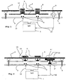
- Figure 2 shows a first embodiment of the invention. This embodiment applies, for example, to a computer keyboard type keyboard or the like.
- a cover 3 of an apparatus has openings 16 to reveal piston keys 4 of a keyboard.
- These keys comprise a conductive part 5 at their base opposite contacts 6 on an electronic card 2.
- a pressure on the top of a key 4 makes it possible to create an electrical connection between the conductive part 5 and the contacts 6, which closes an electrical circuit 13 on the electronic card.
- a return spring 14 then returns the key 4 to its rest position (raised) as shown in FIG.
- At least one key 4 ' is placed under the cover 3 of the electronic device, that is to say without being associated with an opening 16.
- the key 4' is, for example, housed in a niche 15 formed on the internal face of the cover 3.
- the key 4 ' is maintained in permanent pressure so as to provide an electrical connection between its conductive portion 5' and two contacts 6 'underlying formed on the electronic card 2.
- the contacts 6 represent the ends of an electrical intrusion detection circuit 12 passing, for example, by a microprocessor 7 and which is closed by the part 5 '.
- a separation of the electronic card 2 of the cover 3 will cause an opening of this circuit 12, which will for example be detected by the microprocessor 7.
- at least one additional keyboard key is provided and no provision is made for opening facing the hood. This provides a permanently depressed key that does not rise, to open the detection circuit 12, in case of intrusion.
- a first advantage of such an embodiment is to simplify the device of the prior art. It is sufficient to provide additional contacts 6 'on the electronic card 2 and corresponding keyboard keys. The manufacture of such a device is much simpler. In particular, the need to solder a specific component is eliminated.
- a second advantage is the low cost of the security device according to the invention. Indeed, the addition of some keyboard keys and some contacts on the electronic card leads to a small additional cost because it is the usual elements of the keyboard.
- the security device of the invention that applies to an electronic keyboard device consists in giving some of the keys of the keyboard an intrusion detection function whereas, on the contrary, the prior art directs the skilled person to add a specific autonomous element.
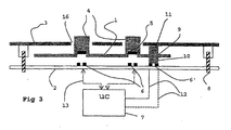
- Figure 3 shows a second preferred embodiment of the present invention, more particularly for a membrane keypad.
- the electrical apparatus contains a membrane keyboard device composed of a membrane 1 and an electronic card 2, operating according to the principle of the prior art represented by FIG. 1 and previously described.
- the membrane 1 contains at least one pin 11 of silicone, whose base contains a conductive portion 10 in permanent electrical connection with contacts 6 'facing the electronic card 2.
- contacts 6' of type "comb" identical to those 6 used for the keyboard function.
- This permanent electrical connection creates a closed electrical loop 12 on the electronic card 2 whose ends are connected, for example, to the microprocessor 7.
- the dimensions of the pin 11 are fixed so as to ensure a sufficient pressure between the contacts 6 'and. the conductive portion 10, to provide the electrical connection.
- This pressure is also advantageously increased to be able to withstand certain shocks such as the fall of the device, its involuntary torsion, etc. For example, it is measured that a pressure of the order of 250 g is sufficient for a conventional terminal payment type device. This value can be reduced in the case of a more compact device and less subject to twisting, for example.
- a separation of the electronic card 2 of the cover 3 will reduce the pressure between the contacts 6 'and the conductive portion 10 until a break in the electrical connection, causing the opening of the loop 12. This opening will be detected by the microprocessor 7.
- This new device thus fulfills simply a switch function taking advantage of the elasticity of the membrane 1 and advantageously adding a conductive portion 10.
- the two essential elements of the safety device according to this second embodiment of the invention are therefore on the one hand to less a conductive portion 10 connected to a membrane 1 and secondly the electronic card 2 having at least one contact 6 opposite, the two elements 10 and 6 'for making a safety switch.
- An advantage of this second embodiment in addition to its simplicity and low cost, is that it requires no additional element, the electronic card 2 and the membrane 1 sufficient to provide the safety function. In particular, it saves the use of a spring switch of a conventional secure keyboard.
- the function of the pin 11 which is to ensure the pressure between the contacts 6 'and the conductive portion 10 after mounting the three elements that are the cover, the membrane and the electronic card, can be filled by a protuberance at the level of the cover 3 or on the card 2, the conductive part 10 always being connected to the membrane 1.
- the contacts 6 and the conductive portion 10 of the device according to the invention can be of any type; it is sufficient that they provide a permanent electrical connection in the normal operating position of the appliance.
- a single contact 6 'and a single conductive portion 10 may suffice if the electric detection circuit is also permanently closed, for example, by a wire conductor connecting the keyboard to the card.
- the electric circuit closed by the security device of the invention comprises two keys or the like of the keyboard. Each key is associated with a single contact 6 'of the card and the two parts conductive conductors 10 are electrically connected by a conductive ink circuit on the membrane for example.
- the device according to the present invention offers great flexibility since it is possible to accumulate easily several of these safety devices, which can be connected in series or in parallel between the same terminals of the microprocessor 7, or on different terminals. Among the many possible combinations, one will choose the one that corresponds to the level of security sought. It is also possible to do without a microprocessor by using for example the device directly as a circuit breaker of the power supply of the device.
Abstract
Description
La présente invention concerne la protection contre les intrusions d'appareils électroniques contenant un clavier pour saisir des données confidentielles. Elle est notamment adaptée aux terminaux bancaires, aux téléphones portables, aux ordinateurs, etc.The present invention relates to protection against intrusions of electronic devices containing a keyboard for entering confidential data. It is particularly suitable for banking terminals, mobile phones, computers, etc.
Une solution de l'art antérieur est représentée à la figure 1. La fonction de clavier est réalisée par une membrane en silicone 1 combinée avec une carte électronique 2. Cette membrane 1 est maintenue en compression entre la carte électronique 2 vissée par des vis 8 dans le capot 3 de l'appareil électronique. La membrane contient des cloques élastiques 4 servant de touches de clavier. Chaque touche 4 traverse le capot 3 par une ouverture 16 de ce dernier pour être accessible de l'extérieur. Chaque cloque comporte à sa base une partie conductrice 5 généralement réalisée en silicone chargé de carbone. Les parties conductrices 5 font face à des contacts 6 de type "peigne", placés sur la carte électronique 2 et composés de deux circuits électriques distincts et entrelacés, reliés respectivement à deux bornes distinctes d'un microprocesseur 7. Selon le mode de fonctionnement classique d'un clavier à membrane, une pression sur une touche 4 du clavier amène la partie conductrice 5 correspondante en contact avec le peigne 6 sous-jacent de manière à fermer un circuit électrique 13 sur la carte électronique 2. Cette fermeture est détectée dans le microprocesseur 7. Un type de fraude consiste à placer des circuits électriques supplémentaires entre les parties conductrices 5 et les contacts 6 afin de détecter les touches appuyées et de saisir les données confidentielles aux dépens de l'usager. Pour cela, il est nécessaire d'intervenir entre la carte 2 et le capot 3. Une solution de l'art antérieur pour éviter ce type de fraude consiste à ajouter un commutateur électrique 9 du commerce sur la carte électronique 2, maintenu en compression entre la carte 2 et le capot 3. Le commutateur 9 et les contacts 6 de la carte électronique 2 communiquent avec le microprocesseur 7. Ces communications sont symbolisées par des liaisons 13. Une séparation de la carte 2 du capot 3 est détectée par le commutateur 9 qui informe le microprocesseur de l'intrusion interdite ; des mesures automatiques anti-fraudes sont alors déployées, comme par exemple la mise en veille de l'appareil, l'effacement des données confidentielles, etc.A solution of the prior art is shown in Figure 1. The keyboard function is performed by a silicone membrane 1 combined with an
Un inconvénient de cette solution de l'art antérieur est qu'elle nécessite l'utilisation d'un élément supplémentaire, un commutateur, qui nécessite un montage spécifique par soudure sur la carte électronique 2, puis un placement particulier entre le capot 3 et la carte 2 dépendant des caractéristiques du commutateur. Un tel dispositif est décrit dans le document US-A-4 644 326.A disadvantage of this solution of the prior art is that it requires the use of an additional element, a switch, which requires a specific mounting by welding on the
De plus, comme les commutateurs utilisés ne sont pas spécifiques à l'application et que leur utilisation se fait en nombre limité (en général, un par clavier), leur coût de revient est élevé pour un clavier sécurisé.In addition, since the switches used are not specific to the application and their use is limited in number (usually one by keyboard), their cost is high for a secure keyboard.
Un autre inconvénient de l'art antérieur est son manque de flexibilité car, si on veut augmenter le niveau de sécurité, il faut ajouter d'autres commutateurs, ce qui devient vite difficile à réaliser en raison de la complexité du montage.Another disadvantage of the prior art is its lack of flexibility because, if one wants to increase the level of security, it is necessary to add other switches, which quickly becomes difficult because of the complexity of the assembly.
Un objet de la présente invention est de proposer une solution alternative moins coûteuse, plus facile à réaliser et plus flexible.An object of the present invention is to provide a less expensive alternative solution, easier to achieve and more flexible.
Pour atteindre ces objets, la présente invention prévoit un dispositif de sécurité pour clavier, comportant des touches et une carte électronique formant clavier et liées à un capot d'un appareil électronique, au moins une touche dédiée du clavier étant maintenue pressée dans un premier état de fonctionnement normal de l'appareil pour fermer un circuit électrique de détection d'intrusion sur la carte électronique, une ouverture du clavier étant détectée par une ouverture dudit circuit, provoquée par le relâchement de ladite touche dédiée.To achieve these objects, the present invention provides a keyboard security device, comprising keys and an electronic card forming a keyboard and linked to a cover of an electronic device, at least one dedicated key of the keyboard being kept pressed in a first state normal operation of the apparatus for closing an electrical intrusion detection circuit on the electronic board, an opening of the keyboard being detected by an opening of said circuit, caused by the release of said dedicated key.
Selon un mode de réalisation de la présente invention, ladite touche dédiée porte au moins une partie conductrice en regard d'au moins un contact de la carte électronique fermant, en position normale de fonctionnement, ledit circuit de détection d'intrusion.According to an embodiment of the present invention, said dedicated key carries at least one conductive portion facing at least one contact of the electronic card closing, in normal operating position, said intrusion detection circuit.
Selon un aspect préféré, l'invention prévoit également un dispositif de sécurité pour clavier à membrane, comportant au moins une membrane et une carte électronique formant clavier et liées à un capot d'un appareil électronique, au moins une membrane contenant une partie conductrice en regard d'au moins un contact sur la carte électronique de manière à détecter un déplacement relatif du contact et de la partie conductrice.According to a preferred aspect, the invention also provides a security device for a membrane keyboard, comprising at least one membrane and an electronic card forming a keyboard and linked to a cover of an electronic device, at least one membrane containing a conductive part in viewing at least one contact on the electronic card so as to detect a relative movement of the contact and the conductive portion.
Selon un mode de réalisation de la présente invention, la partie conductrice et le contact ferment un circuit électrique en position normale de fonctionnement du clavier, le déplacement relatif étant détecté par une ouverture du circuit électrique.According to one embodiment of the present invention, the conductive portion and the contact close an electrical circuit in the normal operating position of the keyboard, the relative movement being detected by an opening of the electrical circuit.
Selon un mode de réalisation de la présente invention, la membrane contient au moins un picot ayant à sa base la partie conductrice.According to one embodiment of the present invention, the membrane contains at least one pin having at its base the conductive portion.
Selon un mode de réalisation de la présente invention, la partie conductrice est dorée.According to one embodiment of the present invention, the conductive portion is gilded.
Selon un mode de réalisation de la présente invention, la partie conductrice est destinée à relier électriquement deux contacts de la carte électronique, les contacts étant, de préférence, des contacts de type "peigne".According to one embodiment of the present invention, the conductive portion is intended to electrically connect two contacts of the electronic card, the contacts being, preferably, contacts of the "comb" type.
L'invention concerne également un terminal de paiement possédant un tel dispositif de sécurité.The invention also relates to a payment terminal having such a security device.
L'invention concerne également un appareil téléphonique possédant un tel dispositif de sécurité.The invention also relates to a telephone device having such a security device.
L'invention concerne en outre un ordinateur possédant un tel dispositif de sécurité.The invention further relates to a computer having such a security device.
Ces objets, caractéristiques et avantages, ainsi que d'autres de la présente invention seront exposés en détail dans la description suivante de modes de réalisation particuliers faite à titre non-limitatif en relation avec les figures jointes parmi lesquelles :
- la figure 1 représente schématiquement un dispositif de sécurité selon l'art antérieur ;
- la figure 2 représente un premier mode de réalisation d'un dispositif de sécurité selon la présente invention, appliqué à un clavier de touches à piston ; et
- la figure 3 représente un second mode de réalisation préféré de la présente invention, qui s'applique particulièrement à un dispositif de clavier à membrane.
- Figure 1 shows schematically a safety device according to the prior art;
- Figure 2 shows a first embodiment of a security device according to the present invention, applied to a piston key keyboard; and
- Figure 3 shows a second preferred embodiment of the present invention, which is particularly applicable to a membrane keypad device.
Les mêmes éléments sont désignés par les mêmes références aux différentes figures.The same elements are designated by the same references in the different figures.
La figure 2 représente un premier mode de réalisation de l'invention. Ce mode de réalisation s'applique, par exemple, à un clavier de type clavier d'ordinateur ou analogue.Figure 2 shows a first embodiment of the invention. This embodiment applies, for example, to a computer keyboard type keyboard or the like.
Dans ce premier mode de réalisation, un capot 3 d'un appareil présente des ouvertures 16 pour laisser apparaître des touches à piston 4 d'un clavier. Ces touches comportent une partie conductrice 5 à leur base en regard de contacts 6 sur une carte électronique 2. Une pression sur le dessus d'une touche 4 permet de créer une connexion électrique entre la partie conductrice 5 et les contacts 6, ce qui ferme un circuit électrique 13 sur la carte électronique. Un ressort 14 de rappel ramène ensuite la touche 4 dans sa position de repos (relevée) telle que représentée sur la figure 2.In this first embodiment, a
Selon l'invention, au moins une touche 4' est placée sous le capot 3 de l'appareil électronique, c'est-à-dire sans être associée à une ouverture 16. La touche 4' est, par exemple, logée dans une niche 15 ménagée en face interne du capot 3. La touche 4' est maintenue en pression permanente de manière à assurer une connexion électrique entre sa partie conductrice 5' et deux contacts 6' sous-jacents formés sur la carte électronique 2. Les contacts 6' représentent les extrémités d'un circuit électrique 12 de détection d'intrusion passant, par exemple, par un microprocesseur 7 et qui est fermé par la partie 5'. Une séparation de la carte électronique 2 du capot 3 entraînera une ouverture de ce circuit 12, qui sera par exemple détectée par le microprocesseur 7. Selon ce mode de réalisation, on prévoit donc au moins une touche de clavier supplémentaire et on ne prévoit pas d'ouverture en regard dans le capot. On obtient ainsi une touche enfoncée en permanence et qui ne se lève, pour ouvrir le circuit électrique de détection 12, qu'en cas d'intrusion.According to the invention, at least one key 4 'is placed under the
Un premier avantage d'une telle réalisation est de simplifier le dispositif de l'art antérieur. Il suffit de prévoir des contacts 6' supplémentaires sur la carte électronique 2 et des touches de clavier correspondantes. La fabrication d'un tel dispositif est beaucoup plus simple. En particulier, on supprime la nécessité de souder un composant spécifique.A first advantage of such an embodiment is to simplify the device of the prior art. It is sufficient to provide additional contacts 6 'on the
Un second avantage est le faible coût du dispositif de sécurité selon l'invention. En effet, l'ajout de quelques touches de clavier et de quelques contacts sur la carte électronique entraîne un surcoût peu important car il s'agit des éléments habituels du clavier.A second advantage is the low cost of the security device according to the invention. Indeed, the addition of some keyboard keys and some contacts on the electronic card leads to a small additional cost because it is the usual elements of the keyboard.
Le dispositif de sécurité de l'invention qui s'applique à un appareil électronique à clavier consiste à donner à certaines des touches du clavier une fonction de détection d'intrusion alors qu'au contraire, l'art antérieur oriente l'homme du métier vers l'ajout d'un élément spécifique autonome.The security device of the invention that applies to an electronic keyboard device consists in giving some of the keys of the keyboard an intrusion detection function whereas, on the contrary, the prior art directs the skilled person to add a specific autonomous element.
La figure 3 représente un second mode de réalisation préféré de la présente invention, destiné, plus particulièrement, à un clavier à membrane.Figure 3 shows a second preferred embodiment of the present invention, more particularly for a membrane keypad.
Selon ce second mode de réalisation, l'appareil électrique contient un dispositif de clavier à membrane, composé d'une membrane 1 et d'une carte électronique 2, fonctionnant selon le principe de l'art antérieur représenté par la figure 1 et décrit précédemment. Selon l'invention, la membrane 1 contient au moins un picot 11 en silicone, dont la base contient une partie conductrice 10 en connexion électrique permanente avec des contacts 6' en regard sur la carte électronique 2. On pourra choisir des contacts 6' de type "peigne" identiques à ceux 6 utilisés pour la fonction de clavier. Cette connexion électrique permanente crée une boucle électrique fermée 12 sur la carte électronique 2 dont les extrémités sont reliées, par exemple, au microprocesseur 7.According to this second embodiment, the electrical apparatus contains a membrane keyboard device composed of a membrane 1 and an
Pour limiter les phénomènes de corrosion qui sont plus importants dans le cas d'une connexion permanente que dans le cas d'une connexion intermittente pour une touche de clavier par exemple, on peut choisir une partie conductrice 10 dorée.To limit the corrosion phenomena which are more important in the case of a permanent connection than in the case of an intermittent connection for a keyboard key, for example, it is possible to choose a gilded conductive part.
De plus, les dimensions du picot 11 sont fixées de façon à garantir une pression suffisante entre les contacts 6' et. la partie conductrice 10, pour assurer la connexion électrique. Cette pression est aussi avantageusement augmentée pour pouvoir résister à certains chocs comme la chute de l'appareil, sa torsion involontaire, etc. A titre d'exemple, on mesure qu'une pression de l'ordre de 250 g est suffisante pour un appareil de type terminal de paiement classique. Cette valeur peut être réduite dans le cas d'un appareil plus compact et moins sujet aux torsions par exemple. Une séparation de la carte électronique 2 du capot 3 entraînera une diminution de la pression entre les contacts 6' et la partie conductrice 10 jusqu'à une rupture de la connexion électrique, entraînant l'ouverture de la boucle 12. Cette ouverture sera détectée par le microprocesseur 7. Ce nouveau dispositif selon la présente invention remplit donc simplement une fonction de commutateur en profitant de l'élasticité de la membrane 1 et en lui ajoutant avantageusement une partie conductrice 10. Les deux éléments essentiels du dispositif de sécurité selon ce second mode de réalisation de l'invention sont donc d'une part au moins une partie conductrice 10 liée à une membrane 1 et d'autre part la carte électronique 2 possédant au moins un contact 6 en regard, les deux éléments 10 et 6' servant à réaliser un commutateur de sécurité.In addition, the dimensions of the
Un avantage de ce second mode de réalisation, outre sa simplicité et son faible coût, est qu'il ne nécessite aucun élément supplémentaire, la carte électronique 2 et la membrane 1 suffisant à assurer la fonction de sécurité. En particulier, on économise le recours à un commutateur à ressort d'un clavier sécurisé classique.An advantage of this second embodiment, in addition to its simplicity and low cost, is that it requires no additional element, the
On notera que la fonction du picot 11 qui est d'assurer la pression entre les contacts 6' et la partie conductrice 10 après montage des trois éléments que sont le capot, la membrane et la carte électronique, peut être remplie par une protubérance au niveau du capot 3 ou sur la carte 2, la partie conductrice 10 étant toujours liée à la membrane 1.Note that the function of the
Selon une autre variante, on pourra utiliser plusieurs membranes, afin par exemple de séparer le dispositif de sécurité et le clavier.According to another variant, it will be possible to use several membranes, for example to separate the safety device and the keyboard.
De plus, les contacts 6 et la partie conductrice 10 du dispositif selon l'invention peuvent être de tout type ; il suffit qu'ils assurent une connexion électrique permanente en position normale de fonctionnement de l'appareil. Par exemple, un seul contact 6' et une seule partie conductrice 10 peuvent suffire si le circuit électrique de détection est par ailleurs fermé à demeure, par exemple, par un conducteur filaire reliant le clavier à la carte. On peut également prévoir que le circuit électrique fermé par le dispositif de sécurité de l'invention comprend deux touches ou analogues du clavier. Chaque touche est associée à un seul contact 6' de la carte et les deux parties conductrices 10 en regard sont reliées électriquement, par un circuit à encre conductrice sur la membrane par exemple.In addition, the
En outre, le dispositif selon la présente invention offre une grande flexibilité puisqu'il est possible de cumuler facilement plusieurs de ces dispositifs de sécurité, qui peuvent être montés en série ou en parallèle entre les mêmes bornes du microprocesseur 7, ou sur différentes bornes. On choisira parmi les multiples combinaisons possibles celle qui correspond au niveau de sécurité recherché. Il est aussi possible de se passer de microprocesseur en utilisant par exemple le dispositif directement comme coupe-circuit de l'alimentation électrique de l'appareil.In addition, the device according to the present invention offers great flexibility since it is possible to accumulate easily several of these safety devices, which can be connected in series or in parallel between the same terminals of the
Enfin, même si le dispositif de sécurité de l'invention remplace celui de l'art antérieur, on notera qu'il reste compatible avec ce dernier ; cela est un autre avantage de l'invention car il est toujours intéressant, au moins pour des raisons psychologiques, de pouvoir cumuler plusieurs dispositifs différents de protection.Finally, even if the safety device of the invention replaces that of the prior art, it will be noted that it remains compatible with the latter; this is another advantage of the invention because it is always interesting, at least for psychological reasons, to accumulate several different protection devices.
Claims (10)
- A security device for a keyboard, comprising keys (4) and an electronic board (2) forming a keyboard and connected to a lid (3) of an electronic device, characterized in that at least one dedicated key (4') of the keyboard is maintained pressed in a first normal operating state of the device to close an electric circuit (12) for detecting an intrusion on the electronic board (2), an opening of the keyboard being detected by an opening of said circuit, caused by the releasing of said dedicated key.
- A security device for a membrane keyboard, comprising at least one membrane (1) and an electronic board (2) forming a keyboard and connected to a lid (3) of an electronic device, characterized in that at least one membrane (1) contains a conductive portion (10) facing at least one contact (6') on the electronic board (2) to detect a relative displacement of the contact (6') and of the conductive portion (10).
- The device of claim 2, characterized in that the conductive portion (10) and the contact (6') close an electric circuit (12) in the normal operating position of the keyboard, the relative displacement being detected by an opening of the electric circuit (12).
- The device of claim 2 or 3, characterized in that the membrane (1) contains at least one pin (11) having at its base the conductive portion (10).
- The device of claim 1, characterized in that said dedicated key (4') supports at least one conductive portion (5') facing at least one contact (6') of the electronic board (2) closing, in normal operating position, said intrusion detection circuit (12).
- The device of any of claims 2 to 5, characterized in that the conductive portion (5', 10) is gilded.
- The device of any of claims 2 to 6, characterized in that the conductive portion (5', 10) is intended to electrically connect two contacts (6') of the electronic board, the contacts (6') being, preferably, "comb"-type contacts.
- A payment terminal provided with the security device of any of the foregoing claims.
- A telephone set provided with the security device of any of the foregoing claims.
- A computer provided with the security device of any of the foregoing claims.
Applications Claiming Priority (3)
| Application Number | Priority Date | Filing Date | Title |
|---|---|---|---|
| FR0013463A FR2815733B1 (en) | 2000-10-20 | 2000-10-20 | SECURE KEYBOARD |
| FR0013463 | 2000-10-20 | ||
| PCT/FR2001/003259 WO2002033717A1 (en) | 2000-10-20 | 2001-10-19 | Secure keyboard |
Publications (2)
| Publication Number | Publication Date |
|---|---|
| EP1346384A1 EP1346384A1 (en) | 2003-09-24 |
| EP1346384B1 true EP1346384B1 (en) | 2006-12-13 |
Family
ID=8855560
Family Applications (1)
| Application Number | Title | Priority Date | Filing Date |
|---|---|---|---|
| EP01982523A Expired - Lifetime EP1346384B1 (en) | 2000-10-20 | 2001-10-19 | Secure keyboard |
Country Status (5)
| Country | Link |
|---|---|
| EP (1) | EP1346384B1 (en) |
| AU (1) | AU2002214083A1 (en) |
| ES (1) | ES2278795T3 (en) |
| FR (1) | FR2815733B1 (en) |
| WO (1) | WO2002033717A1 (en) |
Cited By (4)
| Publication number | Priority date | Publication date | Assignee | Title |
|---|---|---|---|---|
| DE102007040637A1 (en) * | 2007-08-28 | 2009-03-05 | Thales E-Transactions Gmbh | security Key |
| DE102008003264A1 (en) * | 2008-01-04 | 2009-07-09 | Demmel Ag | Keypad for e.g. access control keyboard of bank terminal, has safety contact partner producing constant contact with printed circuit board independent from opening-or closing condition of switch contact partner |
| DE102009054877A1 (en) | 2009-12-17 | 2011-06-22 | ZF Friedrichshafen AG, 88046 | Keyboard for pin-pad for inputting personal identification number, has guide closed against surface by projection of upper part, such that paths are short-circuited, and electronic circuit for retention of short-circuit between paths |
| FR3056370A1 (en) * | 2016-09-22 | 2018-03-23 | Ingenico Group | SUPPORT PART OF A COMPONENT OF A SECURE ELECTRONIC DEVICE |
Families Citing this family (8)
| Publication number | Priority date | Publication date | Assignee | Title |
|---|---|---|---|---|
| FR2860643B1 (en) | 2003-10-07 | 2006-02-17 | Thales Sa | ANTI-INTRUSION DEVICE, IN PARTICULAR FOR AN ELECTRONIC PAYMENT TERMINAL |
| GB0504176D0 (en) * | 2005-03-01 | 2005-04-06 | Keymat Technology Ltd | Anti-tamper devices |
| US7388484B2 (en) * | 2005-08-16 | 2008-06-17 | Honeywell International Inc. | Conductive tamper switch for security devices |
| FR2897702B1 (en) * | 2006-02-22 | 2008-04-25 | Sagem Monetel Soc Par Actions | ANTI-INTRUSION DEVICE |
| FR2901896B1 (en) * | 2006-06-02 | 2008-10-31 | Sagem Monetel Soc Par Actions | DEVICE FOR PROTECTION AGAINST INTRUSIONS OF ELECTRONIC APPARATUS |
| FR2906623B1 (en) | 2006-10-02 | 2009-01-16 | Sagem Monetel Soc Par Actions | PROTECTIVE DEVICE FOR ELECTRONIC CARD |
| FR2929042B1 (en) | 2008-03-21 | 2011-06-03 | Sagem Monetel | DEVICE FOR PROTECTING AN ELECTRONIC SYSTEM |
| FR3036211B1 (en) * | 2015-05-11 | 2017-06-09 | Ingenico Group | OPENING DETECTION OF A DATA ENTRY DEVICE |
Family Cites Families (2)
| Publication number | Priority date | Publication date | Assignee | Title |
|---|---|---|---|---|
| US4644326A (en) * | 1983-06-03 | 1987-02-17 | Secure Keyboards Limited | Unitary key panel |
| DE19600768C2 (en) * | 1996-01-11 | 1998-04-16 | Ibm | Security keyboard |
-
2000
- 2000-10-20 FR FR0013463A patent/FR2815733B1/en not_active Expired - Fee Related
-
2001
- 2001-10-19 ES ES01982523T patent/ES2278795T3/en not_active Expired - Lifetime
- 2001-10-19 AU AU2002214083A patent/AU2002214083A1/en not_active Abandoned
- 2001-10-19 EP EP01982523A patent/EP1346384B1/en not_active Expired - Lifetime
- 2001-10-19 WO PCT/FR2001/003259 patent/WO2002033717A1/en active IP Right Grant
Cited By (13)
| Publication number | Priority date | Publication date | Assignee | Title |
|---|---|---|---|---|
| EP2183729B1 (en) * | 2007-08-28 | 2016-11-02 | VeriFone GmbH | Safety console |
| WO2009027472A1 (en) | 2007-08-28 | 2009-03-05 | Hypercom Gmbh | Safety console |
| DE102007040637B4 (en) * | 2007-08-28 | 2009-04-23 | Thales E-Transactions Gmbh | security Key |
| DE102007040637B8 (en) * | 2007-08-28 | 2009-08-13 | Hypercom Gmbh | security Key |
| EP2183729A1 (en) * | 2007-08-28 | 2010-05-12 | Hypercom GmbH | Safety console |
| DE102007040637A1 (en) * | 2007-08-28 | 2009-03-05 | Thales E-Transactions Gmbh | security Key |
| DE102008003264A1 (en) * | 2008-01-04 | 2009-07-09 | Demmel Ag | Keypad for e.g. access control keyboard of bank terminal, has safety contact partner producing constant contact with printed circuit board independent from opening-or closing condition of switch contact partner |
| DE102008003264B4 (en) * | 2008-01-04 | 2016-07-28 | Demmel Ag | Tamper-proof keyboard with protection against removal of the key caps |
| DE102009054877A1 (en) | 2009-12-17 | 2011-06-22 | ZF Friedrichshafen AG, 88046 | Keyboard for pin-pad for inputting personal identification number, has guide closed against surface by projection of upper part, such that paths are short-circuited, and electronic circuit for retention of short-circuit between paths |
| DE102009054877B4 (en) | 2009-12-17 | 2018-06-28 | Cherry Gmbh | keyboard |
| FR3056370A1 (en) * | 2016-09-22 | 2018-03-23 | Ingenico Group | SUPPORT PART OF A COMPONENT OF A SECURE ELECTRONIC DEVICE |
| WO2018055076A1 (en) * | 2016-09-22 | 2018-03-29 | Ingenico Group | Support part for a component of a secure electronic device |
| US11099415B2 (en) | 2016-09-22 | 2021-08-24 | Ingenico Group | Support part for a component of a secured electronic device |
Also Published As
| Publication number | Publication date |
|---|---|
| WO2002033717A1 (en) | 2002-04-25 |
| EP1346384A1 (en) | 2003-09-24 |
| FR2815733B1 (en) | 2003-03-21 |
| ES2278795T3 (en) | 2007-08-16 |
| FR2815733A1 (en) | 2002-04-26 |
| AU2002214083A1 (en) | 2002-04-29 |
Similar Documents
| Publication | Publication Date | Title |
|---|---|---|
| EP1346384B1 (en) | Secure keyboard | |
| CA2654060C (en) | Device to shield against interference from electrical appliances | |
| EP1193953B1 (en) | Electronic device with collapsible display | |
| EP2194491A1 (en) | Electronic card with control means | |
| EP2146562B1 (en) | Device for protecting an electronic component | |
| EP1126358B1 (en) | Anti-intrusion device | |
| EP1671341B1 (en) | Anti-intrusion device primarily for an electronic payment terminal | |
| EP0896727B1 (en) | Thin integrated circuit card comprising an improved manually actuated switch | |
| EP3921660A1 (en) | Device for checking lack of voltage in an electric circuit | |
| EP2062192B1 (en) | Anti-intrusion system for protecting electronic components | |
| EP2102832B1 (en) | Secured housing | |
| CH713298B1 (en) | Portable object comprising a near-field connection device. | |
| FR2503493A1 (en) | Static capacitative keyboard of rugged construction - has sandwiched behind transparent plate backed by double sided printed circuit board and foam in rigid case | |
| EP1750235A1 (en) | Theft protection device for electronic devices | |
| WO1998003022A9 (en) | Apparatus for controlling and monitoring connections between two different networks | |
| EP2649780B1 (en) | Payment terminal comprising a payment device and a modular interface forming a shroud or hood for pairing a communication terminal | |
| FR2825187A1 (en) | Electronic payment keyboard with intrusion detection, in which movement of keyboard cover from its mounted position triggers an intrusion alarm | |
| FR2947666A1 (en) | DEVICE FOR DETECTING THE OPENING OF A TRAPPER IN EQUIPMENT COMPRISING ONE OR MORE ELECTRONIC CARDS | |
| WO2016180772A1 (en) | Detection of opening of a data input device | |
| FR2823937A1 (en) | Display screen for mobile phone is retractable and can be in an open position or a closed position relative to a fixed point where the closed position partly masks the screen | |
| FR2968492A1 (en) | Electronic payment terminal for payment of purchase of e.g. services, in retail outlet, has case cooperating with lid for authorizing insertion or prohibiting removal of communication terminal into and out of housing |
Legal Events
| Date | Code | Title | Description |
|---|---|---|---|
| PUAI | Public reference made under article 153(3) epc to a published international application that has entered the european phase |
Free format text: ORIGINAL CODE: 0009012 |
|
| 17P | Request for examination filed |
Effective date: 20030516 |
|
| AK | Designated contracting states |
Kind code of ref document: A1 Designated state(s): AT BE CH CY DE DK ES FI FR GB GR IE IT LI LU MC NL PT SE TR |
|
| AX | Request for extension of the european patent |
Extension state: AL LT LV MK RO SI |
|
| RBV | Designated contracting states (corrected) |
Designated state(s): BE ES FR GB |
|
| REG | Reference to a national code |
Ref country code: DE Ref legal event code: 8566 |
|
| RIN1 | Information on inventor provided before grant (corrected) |
Inventor name: PAVAGEAU, STEPHANE |
|
| GRAP | Despatch of communication of intention to grant a patent |
Free format text: ORIGINAL CODE: EPIDOSNIGR1 |
|
| GRAS | Grant fee paid |
Free format text: ORIGINAL CODE: EPIDOSNIGR3 |
|
| GRAA | (expected) grant |
Free format text: ORIGINAL CODE: 0009210 |
|
| AK | Designated contracting states |
Kind code of ref document: B1 Designated state(s): BE ES FR GB |
|
| REG | Reference to a national code |
Ref country code: GB Ref legal event code: FG4D Free format text: NOT ENGLISH |
|
| RAP2 | Party data changed (patent owner data changed or rights of a patent transferred) |
Owner name: SAGEM MONETEL |
|
| GBT | Gb: translation of ep patent filed (gb section 77(6)(a)/1977) |
Effective date: 20070321 |
|
| REG | Reference to a national code |
Ref country code: ES Ref legal event code: FG2A Ref document number: 2278795 Country of ref document: ES Kind code of ref document: T3 |
|
| PLBE | No opposition filed within time limit |
Free format text: ORIGINAL CODE: 0009261 |
|
| STAA | Information on the status of an ep patent application or granted ep patent |
Free format text: STATUS: NO OPPOSITION FILED WITHIN TIME LIMIT |
|
| 26N | No opposition filed |
Effective date: 20070914 |
|
| BECA | Be: change of holder's address |
Owner name: INGENICO FRANCE192, AVENUE CHARLES DE GAULLE, F-92 Effective date: 20090731 |
|
| BECN | Be: change of holder's name |
Owner name: INGENICO FRANCE192, AVENUE CHARLES DE GAULLE, F-92 Effective date: 20090731 |
|
| REG | Reference to a national code |
Ref country code: FR Ref legal event code: CA Ref country code: FR Ref legal event code: CD |
|
| REG | Reference to a national code |
Ref country code: FR Ref legal event code: PLFP Year of fee payment: 15 |
|
| REG | Reference to a national code |
Ref country code: FR Ref legal event code: TP Owner name: COMPAGNIE INDUSTRIELLE ET FINANCIERE D'INGENIE, FR Effective date: 20160111 |
|
| REG | Reference to a national code |
Ref country code: FR Ref legal event code: CD Owner name: INGENICO GROUP, FR Effective date: 20160304 Ref country code: FR Ref legal event code: CA Effective date: 20160304 |
|
| REG | Reference to a national code |
Ref country code: FR Ref legal event code: PLFP Year of fee payment: 16 |
|
| REG | Reference to a national code |
Ref country code: FR Ref legal event code: PLFP Year of fee payment: 17 |
|
| PGFP | Annual fee paid to national office [announced via postgrant information from national office to epo] |
Ref country code: BE Payment date: 20171025 Year of fee payment: 17 |
|
| REG | Reference to a national code |
Ref country code: FR Ref legal event code: PLFP Year of fee payment: 18 |
|
| REG | Reference to a national code |
Ref country code: BE Ref legal event code: MM Effective date: 20181031 |
|
| PG25 | Lapsed in a contracting state [announced via postgrant information from national office to epo] |
Ref country code: BE Free format text: LAPSE BECAUSE OF NON-PAYMENT OF DUE FEES Effective date: 20181031 |
|
| PGFP | Annual fee paid to national office [announced via postgrant information from national office to epo] |
Ref country code: FR Payment date: 20201029 Year of fee payment: 20 Ref country code: GB Payment date: 20201015 Year of fee payment: 20 Ref country code: ES Payment date: 20201103 Year of fee payment: 20 |
|
| REG | Reference to a national code |
Ref country code: GB Ref legal event code: PE20 Expiry date: 20211018 |
|
| REG | Reference to a national code |
Ref country code: ES Ref legal event code: FD2A Effective date: 20220126 |
|
| PG25 | Lapsed in a contracting state [announced via postgrant information from national office to epo] |
Ref country code: GB Free format text: LAPSE BECAUSE OF EXPIRATION OF PROTECTION Effective date: 20211018 |
|
| PG25 | Lapsed in a contracting state [announced via postgrant information from national office to epo] |
Ref country code: ES Free format text: LAPSE BECAUSE OF EXPIRATION OF PROTECTION Effective date: 20211020 |