EP1345013A1 - Débitmètre massique de Coriolis utilisant un mélangeur à tourbillon - Google Patents
Débitmètre massique de Coriolis utilisant un mélangeur à tourbillon Download PDFInfo
- Publication number
- EP1345013A1 EP1345013A1 EP02005868A EP02005868A EP1345013A1 EP 1345013 A1 EP1345013 A1 EP 1345013A1 EP 02005868 A EP02005868 A EP 02005868A EP 02005868 A EP02005868 A EP 02005868A EP 1345013 A1 EP1345013 A1 EP 1345013A1
- Authority
- EP
- European Patent Office
- Prior art keywords
- fluid
- measuring
- measuring tube
- sensor
- pipeline
- Prior art date
- Legal status (The legal status is an assumption and is not a legal conclusion. Google has not performed a legal analysis and makes no representation as to the accuracy of the status listed.)
- Withdrawn
Links
Images

Classifications
-
- G—PHYSICS
- G01—MEASURING; TESTING
- G01F—MEASURING VOLUME, VOLUME FLOW, MASS FLOW OR LIQUID LEVEL; METERING BY VOLUME
- G01F1/00—Measuring the volume flow or mass flow of fluid or fluent solid material wherein the fluid passes through a meter in a continuous flow
- G01F1/76—Devices for measuring mass flow of a fluid or a fluent solid material
- G01F1/78—Direct mass flowmeters
- G01F1/80—Direct mass flowmeters operating by measuring pressure, force, momentum, or frequency of a fluid flow to which a rotational movement has been imparted
- G01F1/84—Coriolis or gyroscopic mass flowmeters
- G01F1/8409—Coriolis or gyroscopic mass flowmeters constructional details
-
- G—PHYSICS
- G01—MEASURING; TESTING
- G01F—MEASURING VOLUME, VOLUME FLOW, MASS FLOW OR LIQUID LEVEL; METERING BY VOLUME
- G01F1/00—Measuring the volume flow or mass flow of fluid or fluent solid material wherein the fluid passes through a meter in a continuous flow
- G01F1/56—Measuring the volume flow or mass flow of fluid or fluent solid material wherein the fluid passes through a meter in a continuous flow by using electric or magnetic effects
- G01F1/58—Measuring the volume flow or mass flow of fluid or fluent solid material wherein the fluid passes through a meter in a continuous flow by using electric or magnetic effects by electromagnetic flowmeters
-
- G—PHYSICS
- G01—MEASURING; TESTING
- G01F—MEASURING VOLUME, VOLUME FLOW, MASS FLOW OR LIQUID LEVEL; METERING BY VOLUME
- G01F1/00—Measuring the volume flow or mass flow of fluid or fluent solid material wherein the fluid passes through a meter in a continuous flow
- G01F1/66—Measuring the volume flow or mass flow of fluid or fluent solid material wherein the fluid passes through a meter in a continuous flow by measuring frequency, phase shift or propagation time of electromagnetic or other waves, e.g. using ultrasonic flowmeters
- G01F1/662—Constructional details
-
- G—PHYSICS
- G01—MEASURING; TESTING
- G01F—MEASURING VOLUME, VOLUME FLOW, MASS FLOW OR LIQUID LEVEL; METERING BY VOLUME
- G01F1/00—Measuring the volume flow or mass flow of fluid or fluent solid material wherein the fluid passes through a meter in a continuous flow
- G01F1/74—Devices for measuring flow of a fluid or flow of a fluent solid material in suspension in another fluid
-
- G—PHYSICS
- G01—MEASURING; TESTING
- G01F—MEASURING VOLUME, VOLUME FLOW, MASS FLOW OR LIQUID LEVEL; METERING BY VOLUME
- G01F1/00—Measuring the volume flow or mass flow of fluid or fluent solid material wherein the fluid passes through a meter in a continuous flow
- G01F1/76—Devices for measuring mass flow of a fluid or a fluent solid material
- G01F1/78—Direct mass flowmeters
- G01F1/80—Direct mass flowmeters operating by measuring pressure, force, momentum, or frequency of a fluid flow to which a rotational movement has been imparted
- G01F1/84—Coriolis or gyroscopic mass flowmeters
- G01F1/8409—Coriolis or gyroscopic mass flowmeters constructional details
- G01F1/8413—Coriolis or gyroscopic mass flowmeters constructional details means for influencing the flowmeter's motional or vibrational behaviour, e.g., conduit support or fixing means, or conduit attachments
- G01F1/8418—Coriolis or gyroscopic mass flowmeters constructional details means for influencing the flowmeter's motional or vibrational behaviour, e.g., conduit support or fixing means, or conduit attachments motion or vibration balancing means
-
- G—PHYSICS
- G01—MEASURING; TESTING
- G01F—MEASURING VOLUME, VOLUME FLOW, MASS FLOW OR LIQUID LEVEL; METERING BY VOLUME
- G01F1/00—Measuring the volume flow or mass flow of fluid or fluent solid material wherein the fluid passes through a meter in a continuous flow
- G01F1/76—Devices for measuring mass flow of a fluid or a fluent solid material
- G01F1/78—Direct mass flowmeters
- G01F1/80—Direct mass flowmeters operating by measuring pressure, force, momentum, or frequency of a fluid flow to which a rotational movement has been imparted
- G01F1/84—Coriolis or gyroscopic mass flowmeters
- G01F1/8409—Coriolis or gyroscopic mass flowmeters constructional details
- G01F1/8422—Coriolis or gyroscopic mass flowmeters constructional details exciters
-
- G—PHYSICS
- G01—MEASURING; TESTING
- G01F—MEASURING VOLUME, VOLUME FLOW, MASS FLOW OR LIQUID LEVEL; METERING BY VOLUME
- G01F1/00—Measuring the volume flow or mass flow of fluid or fluent solid material wherein the fluid passes through a meter in a continuous flow
- G01F1/76—Devices for measuring mass flow of a fluid or a fluent solid material
- G01F1/78—Direct mass flowmeters
- G01F1/80—Direct mass flowmeters operating by measuring pressure, force, momentum, or frequency of a fluid flow to which a rotational movement has been imparted
- G01F1/84—Coriolis or gyroscopic mass flowmeters
- G01F1/845—Coriolis or gyroscopic mass flowmeters arrangements of measuring means, e.g., of measuring conduits
- G01F1/8468—Coriolis or gyroscopic mass flowmeters arrangements of measuring means, e.g., of measuring conduits vibrating measuring conduits
- G01F1/849—Coriolis or gyroscopic mass flowmeters arrangements of measuring means, e.g., of measuring conduits vibrating measuring conduits having straight measuring conduits
-
- G—PHYSICS
- G01—MEASURING; TESTING
- G01N—INVESTIGATING OR ANALYSING MATERIALS BY DETERMINING THEIR CHEMICAL OR PHYSICAL PROPERTIES
- G01N9/00—Investigating density or specific gravity of materials; Analysing materials by determining density or specific gravity
- G01N9/002—Investigating density or specific gravity of materials; Analysing materials by determining density or specific gravity using variation of the resonant frequency of an element vibrating in contact with the material submitted to analysis
Definitions
- the invention relates to a sensor and a method for measuring of at least one physical parameter, especially one Mass flow and / or a density and / or a viscosity, one in a pipeline flowing, especially multi-phase, fluid.
- process measurement and automation technology are used for measurement physical parameters of a fluid flowing in a pipeline, e.g. the mass flow, density and / or viscosity, often such Measuring devices used by means of a fluid flowed through Vibration type sensor and a connected measuring and Operating circuit, in the fluid reaction forces, e.g. with the mass flow corresponding Coriolis forces, corresponding to the density Inertial forces or friction forces corresponding to viscosity, etc., effect and derived from these a respective mass flow, a respective viscosity and / or the respective density of the fluid generate representative measurement signal.
- the fluid reaction forces e.g. with the mass flow corresponding Coriolis forces, corresponding to the density Inertial forces or friction forces corresponding to viscosity, etc.
- Such vibration type sensors are e.g. in WO-A 01/33 174, WO-A 00/57 141, WO-A 98/07 009, WO-A 95/16 897, the WO-A 88/03 261, US-A 60 06 609, US-A 57 96 011, the US-A 53 01 557, US-A 48 76 898, US-A 45 24 610, EP-A 553 939 or EP-A 1 001 254.
- the sensors each include at least one in a measuring tube supported with a curved or straight measuring frame Pipe segment, which is used to generate the above-mentioned reaction forces from an electromechanical excitation arrangement, vibrate during operation is left.
- Vibrations of the pipe segment each have a sensor sensor arrangement reacting to movements of the pipe segment.
- An object of the invention is therefore a method and a Specify sensor that also with inhomogeneous, esp. multiphase, fluids as independent of the momentary as possible Density distribution within the flowing in the connected pipeline Fluids, especially but largely independent of the concentration of any parasitic inhomogeneities, and also as independent of the Installation position of the measuring tube accurate, but at least reproducible and delivers largely robust measurement signals.
- the invention consists in a measuring device for measuring at least a physical parameter of a fluid flowing in a pipeline, especially suitable for implementing the method according to the invention with a such a sensor.
- Fluid-carrying measuring tube for generating with the parameter to be measured corresponding, reacting on the vibrating measuring tube Reaction forces are vibrated in the fluid to be measured and are Vibrations of the measuring tube for generating the at least one measuring signal detected.
- the sensor Invention communicates the at least one measuring tube via an inlet side Inlet pipe section and via an outlet-side outlet pipe section with the Pipeline and are the means for causing the swirl at least partially arranged within the inlet pipe section.
- the means for effecting the twist at least partially within of the at least one measuring tube are the means for effecting the twist at least partially within of the at least one measuring tube.
- the means for effecting the twist at least partially within the pipeline are the means for effecting the twist at least partially within the pipeline.
- the swirler includes at least one fluid flowing into the fluid protruding baffle.
- the swirler is propeller-shaped.
- the swirler is helical.
- the swirler is helical.
- a preferred ninth embodiment of the sensor Invention are the means of causing the twist on the inner wall of the Inlet pipe section and / or fixed to the inner wall of the measuring tube.
- the means for causing the swirl in the direction of flow effective length that is at least equal to a nominal diameter of the pipeline.
- the at least one measuring tube in operation for generating in Fluid acting reaction forces by means of the excitation arrangement vibrated and are vibrations by means of the sensor arrangement Measuring tube detected.
- the physical parameter to be measured is a mass flow.
- the physical parameter to be measured is a density.
- the physical parameter to be measured is a viscosity
- a basic idea of the invention is by means of the rotational movement to induce the swirl axis in the fluid centrifugal forces that are formed are that at least within the measuring tube lumen with respect to the Swirl axis of the rotating "fluid column" as rotationally symmetrical and possible thus largely reproducible density distribution is enforced.
- a any slight falsification in the measurement result, especially in the density measurement value, the especially with liquids with parasitic gaseous inhomogeneities due to the concentration resulting from the centrifugal forces such gas inclusions in the center of the measuring tube lumen can be expected compared to the non-reproducible fluctuations described above be considered negligible.
- the invention is based in particular on the knowledge that the above fluctuations in the measurement signals described are not solely based thereon are due to the fact that e.g. Gas bubbles on the inner wall of the measuring tube attach, but especially that this is essentially chaotic and thus is practically not reproducible or predictable.
- the Fluctuations in the measurement signals when using conventional Sensor with straight or slightly curved measuring tubes for inhomogeneous, esp. multiphase, fluids can to a considerable extent the essentially chaotic distribution of inhomogeneities in the fluid, such as e.g. any bubbled-in gas bubbles, and the result is always one changing but practically undetectable density distribution within the Fluids in the measuring tube lumen are returned.
- An advantage of the invention is that it is practically for all known in-line sensors, esp. also all flow measurement principles are applied and accordingly both in vibration-type sensors and e.g. in magnetic-inductive Sensor or be used in ultrasonic sensors can.
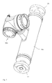
- Fig. 1 is a measuring device with one, preferably in a converter housing 100 housed, sensor 10 and one - not shown here - in housed in an electronics housing 200 and with the sensor 10 electrically connected measuring device electronics shown schematically.
- the Measuring device is used in particular to measure a physical parameter in one, here Not shown, pipeline flowing fluid, esp. A mass flow m and / or to record a density p and / or a viscosity, ⁇ , and convert it into a map the measured value currently representing this parameter. Further can the measuring device e.g. also serve a volume flow of the fluid to eat.
- the measuring device for coupling to a Fieldbus is provided, especially the programmable measuring device electronics a corresponding communication interface for a Data communication, e.g. to send the measurement data to a higher-level programmable logic controller or a higher-level Process control system, on.
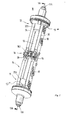
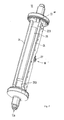
- FIG. 2 and 3 is an embodiment of one as a sensor 10th serving physical-electrical transducer assembly of the vibration type shown.
- the construction of such a converter arrangement is e.g. in the US-A 60 06 609 described in detail.
- Sensor already in standard Coriolis mass flow / Density meters used, e.g. also by the applicant itself the "PROMASS l" series.
- the measuring sensor 10 comprises at least one having an inlet end 11 and an outlet end 12 Measuring tube 13 of predeterminable, elastically deformable measuring tube lumens 13A and of predefinable nominal size.
- Elastic deformation of the measuring tube lumen 13A means here that to generate internal fluid and thus the fluid descriptive reaction forces, namely shear or Frictional forces, but also Coriolis forces and / or Inertial forces, a spatial shape in the operation of the sensor 10 and / or a spatial position of the measuring tube lumen 13A within a Range of elasticity of the measuring tube 13 cyclically in a predetermined manner, esp. periodically, is changed, cf. e.g. US-A 48 01 897, US-A 56 48 616, US-A 57 96 011 and / or US-A 60 06 609.
- any of those already skilled in the art for Coriolis mass flow / density meters known sensor especially a those of the bending vibration type with exclusively or at least partially in a bending vibration mode vibrating, curved or straight Measuring tube, can be used.
- Other suitable embodiments for such transducer arrangements serving as sensors 10 are e.g. in the US-A 53 01 557, US-A 53 57 811, US-A 55 57 973, the US-A 56 02 345, US-A 56 48 616 or in US-A 57 96 011 in detail described, the disclosure of which as to the disclosure of this application is considered to belong.
- Furthermore, e.g. also known to the expert magnetic-inductive sensors or ultrasonic sensors be used.
- the material for the measuring tube 13, which is essentially straight here, is e.g. Titanium alloys particularly suitable. Instead of titanium alloys but also others for such, especially for curved, measuring tubes commonly used materials such as stainless steel, tantalum or Zirconium etc. can be used.
- the measuring tube 13 which communicates in the usual way via an inlet tube piece 13 + and an outlet tube piece 13 # with which the fluid supplying and discharging pipeline, is in a rigid, in particular flexurally and torsionally rigid, and preferably from a converter housing 100 enveloped support frame 14 clamped swinging.
- the measuring tube 13 and the inlet and outlet tube pieces 13 + , 13 # are preferably made in one piece by means of a single tubular semi-finished product; if necessary, they can of course also be in several pieces.
- the support frame 14 is fixed on the inlet pipe section 13 + by means of an inlet plate 213 and on the outlet pipe section 13 # by means of an outlet plate 223, the latter two of which are each pierced by corresponding extension pieces of the measuring tube 13. Furthermore, the support frame 14 has a first side plate 24 and a second side plate 34, which two side plates 24, 34 are fixed to the inlet plate 213 and to the outlet plate 223 in such a way that they are essentially parallel to and spaced from the measuring tube 13 are arranged, cf. 2 and 3. Thus, mutually facing side surfaces of the two side plates 24, 34 are also parallel to one another.
- a longitudinal rod 25 is on the side plates 24, 34 from Measuring tube 13 fixed at a distance, the vibrations of the measuring tube 13th balancing mass serves.
- the longitudinal bar 25 extends, as in FIG. 3 shown, practically parallel to the entire oscillatable length of the Measuring tube 13; however, this is not mandatory, the longitudinal bar 25 can of course, if necessary, be shorter.
- the support frame 14 with the two side plates 24, 34, the inlet plate 213, the outlet plate 223 and possibly the longitudinal rod 25 thus has one Longitudinal line of gravity substantially parallel to an inlet end 11 and the outlet end 12 extends virtually connecting measuring tube center axis 13B.
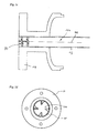
- the inlet pipe section 13 + is preferably formed with a first flange 19 and the outlet pipe section 13 # with a second flange 20, cf. Fig. 1;
- a second flange 20, cf. Fig. 1 instead of the flanges 19, 20, for example, so-called triclamp connections, as indicated in FIG. 2 or 3, can also be used for the detachable connection to the pipeline.
- the measuring tube 13 can also be connected directly to the pipeline, for example by welding or brazing etc.
- the measuring tube 13 is used to generate the above-mentioned reaction forces in the fluid in operation of the sensor 10, driven by one with the measuring tube coupled electro-mechanical excitation arrangement 16, at a Predeterminable oscillation frequency, especially one of a density, ⁇ , of the fluid dependent natural resonance frequency, in the so-called useful mode vibrate and thus elastically deformed in a predetermined way.
- the vibrating measuring tube 13 as in such transducer arrangements of the bending vibration type common from one static rest position spatially, esp. laterally, deflected; the same applies practically also for those transducer arrangements in which one or more curved Measuring tubes in operation are known to have a boom vibration corresponding, virtually connecting the respective inlet and outlet ends Longitudinal axis or for those in which one or more straight measuring tubes only execute plane bending vibrations around the longitudinal axis of the measuring tube.
- a transducer arrangement of the radial vibration type is used and the vibrating measuring tube is symmetrically deformed in the usual way the latter would essentially remain in its static rest position.
- the excitation arrangement 16 is used to generate an excitation force F exc acting on the measuring tube 13 by converting an electrical excitation power P exc which is fed in by the measuring device electronics.
- the excitation power P exc serves practically only to compensate for the power component extracted from the vibration system via mechanical and fluid-internal friction.
- the excitation power P exc is preferably set as precisely as possible so that essentially the vibrations of the measuring tube 13 in the useful mode, for example those with a lowest resonance frequency, are maintained.
- the excitation arrangement 16 in the exemplary embodiment has a rigid, electromagnetically and / or electrodynamically driven lever arrangement 15 with a cantilever 154 fixed to the measuring tube 13 and with a yoke 163 on.
- the yoke 163 is also fixed to one end of the arm 154 at a distance from the measuring tube 13, in such a way that it is arranged above the measuring tube 13 and transversely to it.
- a metal disc, for example, which receives the measuring tube 13 in a bore can serve as the arm 154.
- The, here T-shaped, lever arrangement 15 is preferably, as can be seen in FIG. 2, arranged so that it acts approximately in the middle between the inlet and outlet ends 11, 12 on the measuring tube 13, which means that this is centered during operation performs its greatest lateral deflection.
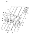
- the excitation arrangement 16 For driving the lever arrangement 15, the excitation arrangement 16 4, a first excitation coil 26 and an associated first Permanent magnetic armature 27 and a second excitation coil 36 and one associated second permanent magnetic armature 37.
- the two, electrical preferably connected in series, excitation coils 26, 36 are on both sides of the Measuring tube 13 below the yoke 163 on the support frame 14, especially releasable, see above fixes that they with their respective anchor 27 and 37 in operation in Interact; otherwise the two excitation coils 26, 36, if necessary, of course, also be connected in parallel to each other.
- the two anchors 27, 37 are such from each other fixed at a distance to the yoke 163 that in operation of the sensor 10 the Armature 27 essentially from a magnetic field of the excitation coil 26 and Armature 37 essentially from a magnetic field of excitation coil 36 enforced and due to appropriate electrodynamic and / or electromagnetic force effects is moved.
- the movements generated by means of the magnetic fields of the excitation coils 26, 36 the armatures 27, 37 are placed on the measuring tube 13 via yoke 163 and bracket 154 transfer. These movements of the armature 27, 37 are designed so that the Yoke 163 alternately in the direction of the side plate 24 or in the direction of the Side plate 34 is deflected from its rest position.
- a corresponding, for already mentioned measuring tube center axis 13B parallel axis of rotation of the Lever arrangement 15 can e.g. through the boom 154.
- the support frame 14 further preferably comprises one with the side plates 24, 34, releasably, connected bracket 29 for the electromechanical Excitation arrangement 16.
- the measuring sensor of the exemplary embodiment in the measuring tube 13 due to a torque acting on this via lever arrangement 15 at the same time as the lateral deflections, at least in sections forced torsional rotation about the measuring tube central axis 13B, so that this practically in a mixed serving as utility fashion Bending vibration torsion mode swings.
- the rotation of the measuring tube 13 can be designed so that a lateral deflection of the measuring tube 13 spaced end of the boom 154 either the same or opposite is directed to the lateral deflection of the measuring tube 13.
- Measuring tube 13 can torsional vibrations in the former case corresponding first bending vibration torsion mode or in one of the latter case corresponding to the second bending vibration torsion mode execute, with the sensor 10 according to the embodiment natural resonance frequency of the second bending vibration torsion mode from e.g. 900 Hz is almost twice as high as that of the first Flexural and torsional mode.
- the measuring tube 13 vibrates operationally only in the second bending vibration torsion mode is in advantageously based on the eddy current principle Magnetic brake assembly 217 integrated into the excitation assembly 16, this serves to stabilize the position of this axis of rotation.
- the Magnetic brake assembly 217 can thus be ensured that the Measuring tube 13 always vibrates in the second bending vibration torsion mode thus any external interference on the measuring tube 13 does not become one spontaneous change to another, especially not in the first one, Lead bending vibration torsion mode.
- Details of such Magnetic brake arrangements are e.g. in detail in US-A 60 06 609 described; furthermore the use of such Magnetic brake arrangements already from sensors of the series mentioned "PROMASS l" known.
- the imaginary measuring tube center axis 13B is practically easily deformed and thus at the vibrations are not a plane but a slightly curved surface spans. Furthermore, one lying in this area points through the center the trajectory described the axis of the measuring tube the smallest curvature of all path curves described by the measuring tube center axis.
- the measuring sensor 10 further comprises a sensor arrangement 60 which, by means of at least one first sensor 17 which reacts to vibrations of the measuring tube 13, generates a first, in particular analog, sensor signal s 1 which represents this.
- the sensor 17 can, for example, as is customary in the case of such sensors, be formed by means of a permanent magnet armature fixed to the measuring tube 13 and interacting with a sensor coil held by the support frame 14.
- sensors 17 are those based on the electrodynamic principle, a speed of the deflections of the Detect the measuring tube.
- accelerometer electrodynamic or path-measuring resistive or optical Sensors are used.
- others can do that too Known to those skilled in the art and suitable for the detection of such vibrations Sensors are used.
- the sensor arrangement 60 further comprises a second sensor 18, in particular identical to the first sensor 17, by means of which it supplies a second sensor signal s 2 , which also represents vibrations of the measuring tube.
- the two sensors 17, 18 are spaced apart from one another along the measuring tube 13, in particular also at an equal distance from the center of the measuring tube 13, in the measuring sensor 10 so that by means of the sensor arrangement 60 both the inlet-side and outlet-side vibrations of the measuring tube 13 recorded locally and mapped into the corresponding sensor signals s 1 and s 2 .
- the first and possibly the second sensor signal s 1 or s 2 which usually each have a signal frequency corresponding to the instantaneous oscillation frequency of the measuring tube 13, are fed to the measuring device electronics, not shown here.
- the excitation arrangement 16 is fed by means of a likewise oscillating, unipolar or bi-polar excitation current i exc of adjustable amplitude and of an adjustable excitation frequency f exc supplied by the measuring device electronics in such a way that the excitation coils 26, 36 are in operation through which the magnetic fields required for moving the armatures 27, 37 are generated.
- the excitation force F exc required for vibrating the measuring tube 13 in the manner known to the person skilled in the art for example on the basis of the sensor signals s 1 or s 2 by means of a current and / or voltage control circuit, with regard to its amplitude and Control loop with regard to its frequency, can be monitored and adjusted.
- the excitation current i exc supplied by the measuring device electronics is preferably sinusoidal; however, it can also be, for example, a pulsating, a triangular or a rectangular alternating current.
- the excitation frequency f exc of the excitation current i exc corresponds, as is customary in the case of vibration measuring devices of the type described, to the predetermined oscillation frequency of the measuring tube 13 and is therefore preferably set to an instantaneous natural resonance frequency of the fluid-carrying measuring tube 13.
- an ultrasonic flow sensor is used as the measuring sensor, is an ultrasonic transducer in the manner known to those skilled in the art Excitation arrangement used, which, through which an excitation current flows, Coupled ultrasonic waves into the fluid in the measuring tube. Then also serves usually an ultrasonic transducer as a sensor arrangement, the Ultrasonic waves are coupled out of the fluid and into a corresponding one Measuring voltage converted.
- the sensor 10 shown in FIGS. 1 to 4 is practically a multivariable sensor with which, alternately or simultaneously, for example, the mass flow m is based on the two sensor signals s 1 , s 2 and / or the density ⁇ is based on the excitation frequency f exc and / or the viscosity, ⁇ , of the fluid can be detected on the basis of the excitation current i exc , the sensor signals, the excitation current or the above-mentioned measuring voltages are used in the following to further explain the invention in the sense of better uniformity and clarity under the term "Measurement signal" summarized.
- the measurement signal corresponding to the parameter to be measured for example the sensor signal s 1 or the excitation current i exc , depends to a considerable extent on an instantaneous density distribution in the fluid flowing in the measuring tube 13, but especially of a concentration and a distribution of possible parasitic inhomogeneities can be influenced.
- means are provided according to the invention in an inlet area of the measuring sensor 10 or at least in the vicinity thereof, which have a swirl in the inflowing fluid and thus in the fluid flowing within the measuring tube lumen a rotational movement relative to the measuring tube 13 around an imaginary axis of rotation lying in the direction of flow, which in the preferred case of a straight measuring tube practically coincides with the measuring tube center axis 13B.
- the means for effecting the swirl comprise at least one swirler 30 protruding into the flowing fluid.
- the swirler 30, which preferably rests in the tube lumen, can be, for example, a separate, propeller-shaped, helical or also helical component which, as in the FIGS 5a to d, at least partially in the inlet pipe section 13 + or, for example, at least partially directly in the measuring tube 13.
- the means for causing the swirl as shown in FIGS. 5a and 5b, are designed as a helical or also helical component, they can be held under mechanical tension in the inlet pipe section 13 + and / or the measuring pipe 13 inserted and thus held pressed against the respective inner wall by means of spring force.
- the means for generating the twist in particular the swirler 30 designed as a separate component, at least partially also within the pipeline supplying the fluid to the sensor 10 can be arranged. Furthermore, the means for generating the swirl e.g. also through a section of the pipeline that is angled several times be educated.
- the swirler 30 comprises at least one guide plate 30a protruding obliquely into the flowing fluid, in particular shaped in the manner of a turbine swirl vane.
- the swirler comprises two or more such baffles 30a, 30b, 30c, 30d, which, as indicated in FIG. 4d, are arranged in such a way that the swirler 30 is designed, for example in the manner of a turbine stator, as a stator.
- the at least one baffle plate 30a is preferably fixed to the inner wall of the inlet pipe section 13 + ; if necessary, however, it can also be attached to the inner wall of the pipeline supplying the fluid, for example.
- the means for effecting the swirl are designed in the manner of a drawn barrel as a train formed in the inner wall of the inlet pipe section 13 + and / or the measuring pipe 13.
- the means for causing the swirl should advantageously have an effective length in the direction of flow which is at least equal to a nominal diameter of the pipeline. Furthermore, particularly good measurement results could also be achieved if a reduction in the effective cross section of the inlet pipe section 13 + and / or the pipeline resulting from the installation of the swirler 30 was either kept very low or was compensated for by an increase in its respective nominal cross section.
- a particular advantage of the invention is the fact that the means for Effect the sensor using the twist practically in any Installation position, especially in the course of an essentially horizontal one Pipeline installed, with essentially constant measuring accuracy can be operated.
- Another advantage of the invention is that when it is applied to vibration-type sensors to vibrate the measuring tube 13, an excitation current i exc , which is considerably lower than that of conventional sensors, and thus less energy is required, especially with a high proportion of gaseous gases Inhomogeneities in the fluid to be measured.
Priority Applications (9)
| Application Number | Priority Date | Filing Date | Title |
|---|---|---|---|
| EP02005868A EP1345013A1 (fr) | 2002-03-14 | 2002-03-14 | Débitmètre massique de Coriolis utilisant un mélangeur à tourbillon |
| CNB038059657A CN100353150C (zh) | 2002-03-14 | 2003-03-12 | 测量物理参数的方法以及实施该方法的测量传感器和仪表 |
| PCT/EP2003/002535 WO2003076880A1 (fr) | 2002-03-14 | 2003-03-12 | Debitmetre massique fonctionnant selon la force de coriolis dote d'un dispositif generateur de tourbillons |
| EP03709777A EP1483552A1 (fr) | 2002-03-14 | 2003-03-12 | Debitmetre massique fonctionnant selon la force de coriolis dote d'un dispositif generateur de tourbillons |
| AU2003214120A AU2003214120A1 (en) | 2002-03-14 | 2003-03-12 | Coriolis mass flowmeter comprising a swirl generator |
| RU2004130465/28A RU2297600C2 (ru) | 2002-03-14 | 2003-03-12 | Способ измерения параметров текучей силы, протекающей в трубе, измерительный преобразователь и измерительный прибор |
| CA002477799A CA2477799A1 (fr) | 2002-03-14 | 2003-03-12 | Transducteur et methode pour mesurer le debit d'un fluide dans un tuyau |
| JP2003575057A JP4108041B2 (ja) | 2002-03-14 | 2003-03-12 | 配管を流れる流体を計測するための変換器およびその方法 |
| US10/386,930 US6880410B2 (en) | 2002-03-14 | 2003-03-13 | Transducer and method for measuring a fluid flowing in a pipe |
Applications Claiming Priority (1)
| Application Number | Priority Date | Filing Date | Title |
|---|---|---|---|
| EP02005868A EP1345013A1 (fr) | 2002-03-14 | 2002-03-14 | Débitmètre massique de Coriolis utilisant un mélangeur à tourbillon |
Publications (1)
| Publication Number | Publication Date |
|---|---|
| EP1345013A1 true EP1345013A1 (fr) | 2003-09-17 |
Family
ID=27763385
Family Applications (2)
| Application Number | Title | Priority Date | Filing Date |
|---|---|---|---|
| EP02005868A Withdrawn EP1345013A1 (fr) | 2002-03-14 | 2002-03-14 | Débitmètre massique de Coriolis utilisant un mélangeur à tourbillon |
| EP03709777A Withdrawn EP1483552A1 (fr) | 2002-03-14 | 2003-03-12 | Debitmetre massique fonctionnant selon la force de coriolis dote d'un dispositif generateur de tourbillons |
Family Applications After (1)
| Application Number | Title | Priority Date | Filing Date |
|---|---|---|---|
| EP03709777A Withdrawn EP1483552A1 (fr) | 2002-03-14 | 2003-03-12 | Debitmetre massique fonctionnant selon la force de coriolis dote d'un dispositif generateur de tourbillons |
Country Status (7)
| Country | Link |
|---|---|
| EP (2) | EP1345013A1 (fr) |
| JP (1) | JP4108041B2 (fr) |
| CN (1) | CN100353150C (fr) |
| AU (1) | AU2003214120A1 (fr) |
| CA (1) | CA2477799A1 (fr) |
| RU (1) | RU2297600C2 (fr) |
| WO (1) | WO2003076880A1 (fr) |
Cited By (6)
| Publication number | Priority date | Publication date | Assignee | Title |
|---|---|---|---|---|
| EP1876427A1 (fr) * | 2006-07-05 | 2008-01-09 | Landis+Gyr GmbH | Débitmètre à ultrasons avec un dispositif déclencant des turbulences dans la zone d'arrivée |
| CN103353320A (zh) * | 2013-07-03 | 2013-10-16 | 太原太航科技有限公司 | 基于混频算法的科氏质量流量计信号处理方法 |
| CN104296816A (zh) * | 2014-10-24 | 2015-01-21 | 成都安迪生测量有限公司 | 一种小型液体流量计 |
| WO2015096934A1 (fr) * | 2013-12-27 | 2015-07-02 | Endress+Hauser Flowtec Ag | Capteur de mesure de type à vibrations |
| CN107131921A (zh) * | 2016-02-26 | 2017-09-05 | 高准公司 | 用于计量电子器件的低功率模式 |
| CN108088730A (zh) * | 2017-12-21 | 2018-05-29 | 浙江华友钴业股份有限公司 | 一种三元前驱体金属盐溶液的精确配料方法 |
Families Citing this family (17)
| Publication number | Priority date | Publication date | Assignee | Title |
|---|---|---|---|---|
| US7284449B2 (en) | 2004-03-19 | 2007-10-23 | Endress + Hauser Flowtec Ag | In-line measuring device |
| WO2005095901A2 (fr) * | 2004-03-19 | 2005-10-13 | Endress+Hauser Flowtec Ag | Debitmetre massique de type coriolis |
| US7040181B2 (en) | 2004-03-19 | 2006-05-09 | Endress + Hauser Flowtec Ag | Coriolis mass measuring device |
| DE102004018326B4 (de) | 2004-04-13 | 2023-02-23 | Endress + Hauser Flowtec Ag | Vorrichtung und Verfahren zum Messen einer Dichte und/oder einer Viskosität eines Fluids |
| EP1987327A1 (fr) | 2005-12-27 | 2008-11-05 | Endress+Hauser Flowtec AG | Dispositifs de mesure en ligne et procede de correction d erreurs de mesure dans des dispositifs de mesure en ligne |
| US7360453B2 (en) | 2005-12-27 | 2008-04-22 | Endress + Hauser Flowtec Ag | In-line measuring devices and method for compensation measurement errors in in-line measuring devices |
| US7360452B2 (en) | 2005-12-27 | 2008-04-22 | Endress + Hauser Flowtec Ag | In-line measuring devices and method for compensation measurement errors in in-line measuring devices |
| EP2286187A1 (fr) | 2008-05-01 | 2011-02-23 | Micro Motion, Inc. | Débitmètre vibratoire à très haute fréquence |
| DE102008002028A1 (de) | 2008-05-28 | 2009-12-03 | Endress + Hauser Flowtec Ag | Messzelle, welche lösbar an einer dafür vorgesehenen Messvorrichtung anbringbar ist |
| DE102008002027A1 (de) | 2008-05-28 | 2009-12-03 | Endress + Hauser Flowtec Ag | Messzelle, welche lösbar an einer dafür vorgesehenen Messvorrichtung anbringbar ist |
| US8511144B2 (en) * | 2010-01-11 | 2013-08-20 | General Electric Company | Torsional sensor, method thereof, and system for measurement of fluid parameters |
| CN102749266B (zh) * | 2012-07-19 | 2016-12-21 | 青岛澳邦量器有限责任公司 | 流体特性测量器及测量流体密度的方法 |
| EP3006903B1 (fr) * | 2014-10-10 | 2016-12-07 | SICK Engineering GmbH | Débitmètre destiné à mesurer un paramètre d'un flux formé par un fluide |
| CN106768105B (zh) * | 2016-12-26 | 2019-12-31 | 威海市天罡仪表股份有限公司 | 采集切向速度测量流量的方法及装置 |
| DE102017129036A1 (de) * | 2017-12-06 | 2019-06-06 | Endress+Hauser Flowtec Ag | Verfahren zum Bestimmen der Viskosität eines Mediums mittels eines Coriolis-Massedurchflussmessers und Coriolis- Massedurchflussmesser zur Durchführung des Verfahrens |
| CN110657847B (zh) * | 2019-09-17 | 2020-11-03 | 北京纳米能源与系统研究所 | 摩擦电式浮子流量传感装置及流量检测设备 |
| DE102021131866A1 (de) | 2021-12-03 | 2023-06-07 | Endress+Hauser Flowtec Ag | Verfahren zum Detektieren eines Fremdkörpers in einem Medium |
Citations (4)
| Publication number | Priority date | Publication date | Assignee | Title |
|---|---|---|---|---|
| US4420983A (en) * | 1980-02-28 | 1983-12-20 | The Marconi Company Limited | Mass flow measurement device |
| JPH0953969A (ja) * | 1995-08-18 | 1997-02-25 | Tokico Ltd | 振動式測定装置 |
| JPH10281846A (ja) * | 1997-04-09 | 1998-10-23 | Oval Corp | コリオリ流量計を利用したパターン認識法による多相流量計 |
| US6318156B1 (en) * | 1999-10-28 | 2001-11-20 | Micro Motion, Inc. | Multiphase flow measurement system |
Family Cites Families (1)
| Publication number | Priority date | Publication date | Assignee | Title |
|---|---|---|---|---|
| GB9215043D0 (en) * | 1992-07-15 | 1992-08-26 | Flow Inc K | Fluid mass flow meters |
-
2002
- 2002-03-14 EP EP02005868A patent/EP1345013A1/fr not_active Withdrawn
-
2003
- 2003-03-12 RU RU2004130465/28A patent/RU2297600C2/ru active
- 2003-03-12 JP JP2003575057A patent/JP4108041B2/ja not_active Expired - Fee Related
- 2003-03-12 CN CNB038059657A patent/CN100353150C/zh not_active Expired - Fee Related
- 2003-03-12 CA CA002477799A patent/CA2477799A1/fr not_active Abandoned
- 2003-03-12 WO PCT/EP2003/002535 patent/WO2003076880A1/fr active Application Filing
- 2003-03-12 AU AU2003214120A patent/AU2003214120A1/en not_active Abandoned
- 2003-03-12 EP EP03709777A patent/EP1483552A1/fr not_active Withdrawn
Patent Citations (4)
| Publication number | Priority date | Publication date | Assignee | Title |
|---|---|---|---|---|
| US4420983A (en) * | 1980-02-28 | 1983-12-20 | The Marconi Company Limited | Mass flow measurement device |
| JPH0953969A (ja) * | 1995-08-18 | 1997-02-25 | Tokico Ltd | 振動式測定装置 |
| JPH10281846A (ja) * | 1997-04-09 | 1998-10-23 | Oval Corp | コリオリ流量計を利用したパターン認識法による多相流量計 |
| US6318156B1 (en) * | 1999-10-28 | 2001-11-20 | Micro Motion, Inc. | Multiphase flow measurement system |
Non-Patent Citations (2)
| Title |
|---|
| PATENT ABSTRACTS OF JAPAN vol. 1997, no. 06 30 June 1997 (1997-06-30) * |
| PATENT ABSTRACTS OF JAPAN vol. 1999, no. 01 29 January 1999 (1999-01-29) * |
Cited By (7)
| Publication number | Priority date | Publication date | Assignee | Title |
|---|---|---|---|---|
| EP1876427A1 (fr) * | 2006-07-05 | 2008-01-09 | Landis+Gyr GmbH | Débitmètre à ultrasons avec un dispositif déclencant des turbulences dans la zone d'arrivée |
| CN103353320A (zh) * | 2013-07-03 | 2013-10-16 | 太原太航科技有限公司 | 基于混频算法的科氏质量流量计信号处理方法 |
| WO2015096934A1 (fr) * | 2013-12-27 | 2015-07-02 | Endress+Hauser Flowtec Ag | Capteur de mesure de type à vibrations |
| US9897473B2 (en) | 2013-12-27 | 2018-02-20 | Endress + Hauser Flowtec Ag | Measuring transducer of vibration-type |
| CN104296816A (zh) * | 2014-10-24 | 2015-01-21 | 成都安迪生测量有限公司 | 一种小型液体流量计 |
| CN107131921A (zh) * | 2016-02-26 | 2017-09-05 | 高准公司 | 用于计量电子器件的低功率模式 |
| CN108088730A (zh) * | 2017-12-21 | 2018-05-29 | 浙江华友钴业股份有限公司 | 一种三元前驱体金属盐溶液的精确配料方法 |
Also Published As
| Publication number | Publication date |
|---|---|
| RU2004130465A (ru) | 2005-05-10 |
| WO2003076880A1 (fr) | 2003-09-18 |
| JP2005520129A (ja) | 2005-07-07 |
| AU2003214120A1 (en) | 2003-09-22 |
| RU2297600C2 (ru) | 2007-04-20 |
| CN100353150C (zh) | 2007-12-05 |
| JP4108041B2 (ja) | 2008-06-25 |
| EP1483552A1 (fr) | 2004-12-08 |
| CA2477799A1 (fr) | 2003-09-18 |
| CN1643346A (zh) | 2005-07-20 |
Similar Documents
| Publication | Publication Date | Title |
|---|---|---|
| EP1345013A1 (fr) | Débitmètre massique de Coriolis utilisant un mélangeur à tourbillon | |
| EP2502032B1 (fr) | Système de mesure muni d'un ensemble de tubes présentant deux tubes de mesure parcourus en parallèle par un milieu et procédé de surveillance dudit ensemble du tubes | |
| EP2519805B1 (fr) | Système de mesure comportant un convertisseur de mesure de type vibrant et procédé pour mesurer une différence de pression | |
| EP1759178B1 (fr) | Transducteur du type transducteur de vibrations | |
| EP2606319B1 (fr) | Système de mesure présentant un transducteur de type vibratoire | |
| WO2010103004A2 (fr) | Système de mesure avec un convertisseur de mesure du type vibratoire | |
| EP1253408A1 (fr) | Transducteur de mesure du type vibrant | |
| WO2012062551A1 (fr) | Système de mesure comprenant un convertisseur de mesure du type à vibration | |
| WO2009080553A1 (fr) | Convertisseur de mesure du type à vibrations | |
| EP2519806B1 (fr) | Système de mesure avec transducteur de type à vibrations | |
| EP1291639B1 (fr) | Appareil de mesure de la viscosité | |
| DE102006062600A1 (de) | Verfahren zum Inbetriebnehmen und/oder Überwachen eines In-Line-Meßgeräts | |
| EP3729011A1 (fr) | Dispositif de mesure du débit massique de coriolis | |
| DE10358663B4 (de) | Coriolis-Massedurchfluß-Meßgerät | |
| EP2201337A1 (fr) | Transducteur de vibrations | |
| DE10235322A1 (de) | Meßwandler vom Vibrationstyp | |
| EP2519804B1 (fr) | Système de mesure comportant un convertisseur de mesure de type vibrant | |
| DE10220827A1 (de) | Messwandler vom Vibrationstyp | |
| DE102010000759A1 (de) | Meßsystem mit einem Meßwandler vom Vibrationstyp | |
| DE102010000760B4 (de) | Meßsystem mit einem Meßwandler vom Vibrationstyp zum Messen eines statischen Drucks in einem strömenden Medium | |
| DE102010000761A1 (de) | Meßsystem mit einem Meßwandler vom Vibrationstyp | |
| DE102004007889A1 (de) | Coriolis-Massedurchfluß-Meßgerät | |
| WO2005057137A2 (fr) | Debitmetre massique de coriolis |
Legal Events
| Date | Code | Title | Description |
|---|---|---|---|
| PUAI | Public reference made under article 153(3) epc to a published international application that has entered the european phase |
Free format text: ORIGINAL CODE: 0009012 |
|
| AK | Designated contracting states |
Kind code of ref document: A1 Designated state(s): AT BE CH CY DE DK ES FI FR GB GR IE IT LI LU MC NL PT SE TR |
|
| AX | Request for extension of the european patent |
Extension state: AL LT LV MK RO SI |
|
| AKX | Designation fees paid | ||
| REG | Reference to a national code |
Ref country code: DE Ref legal event code: 8566 |
|
| STAA | Information on the status of an ep patent application or granted ep patent |
Free format text: STATUS: THE APPLICATION IS DEEMED TO BE WITHDRAWN |
|
| 18D | Application deemed to be withdrawn |
Effective date: 20040318 |