EP1345013A1 - Coriolis mass flow meter with swirl mixer - Google Patents
Coriolis mass flow meter with swirl mixer Download PDFInfo
- Publication number
- EP1345013A1 EP1345013A1 EP02005868A EP02005868A EP1345013A1 EP 1345013 A1 EP1345013 A1 EP 1345013A1 EP 02005868 A EP02005868 A EP 02005868A EP 02005868 A EP02005868 A EP 02005868A EP 1345013 A1 EP1345013 A1 EP 1345013A1
- Authority
- EP
- European Patent Office
- Prior art keywords
- fluid
- measuring
- measuring tube
- sensor
- pipeline
- Prior art date
- Legal status (The legal status is an assumption and is not a legal conclusion. Google has not performed a legal analysis and makes no representation as to the accuracy of the status listed.)
- Withdrawn
Links
Images

Classifications
-
- G—PHYSICS
- G01—MEASURING; TESTING
- G01F—MEASURING VOLUME, VOLUME FLOW, MASS FLOW OR LIQUID LEVEL; METERING BY VOLUME
- G01F1/00—Measuring the volume flow or mass flow of fluid or fluent solid material wherein the fluid passes through a meter in a continuous flow
- G01F1/76—Devices for measuring mass flow of a fluid or a fluent solid material
- G01F1/78—Direct mass flowmeters
- G01F1/80—Direct mass flowmeters operating by measuring pressure, force, momentum, or frequency of a fluid flow to which a rotational movement has been imparted
- G01F1/84—Coriolis or gyroscopic mass flowmeters
- G01F1/8409—Coriolis or gyroscopic mass flowmeters constructional details
-
- G—PHYSICS
- G01—MEASURING; TESTING
- G01F—MEASURING VOLUME, VOLUME FLOW, MASS FLOW OR LIQUID LEVEL; METERING BY VOLUME
- G01F1/00—Measuring the volume flow or mass flow of fluid or fluent solid material wherein the fluid passes through a meter in a continuous flow
- G01F1/56—Measuring the volume flow or mass flow of fluid or fluent solid material wherein the fluid passes through a meter in a continuous flow by using electric or magnetic effects
- G01F1/58—Measuring the volume flow or mass flow of fluid or fluent solid material wherein the fluid passes through a meter in a continuous flow by using electric or magnetic effects by electromagnetic flowmeters
-
- G—PHYSICS
- G01—MEASURING; TESTING
- G01F—MEASURING VOLUME, VOLUME FLOW, MASS FLOW OR LIQUID LEVEL; METERING BY VOLUME
- G01F1/00—Measuring the volume flow or mass flow of fluid or fluent solid material wherein the fluid passes through a meter in a continuous flow
- G01F1/66—Measuring the volume flow or mass flow of fluid or fluent solid material wherein the fluid passes through a meter in a continuous flow by measuring frequency, phase shift or propagation time of electromagnetic or other waves, e.g. using ultrasonic flowmeters
- G01F1/662—Constructional details
-
- G—PHYSICS
- G01—MEASURING; TESTING
- G01F—MEASURING VOLUME, VOLUME FLOW, MASS FLOW OR LIQUID LEVEL; METERING BY VOLUME
- G01F1/00—Measuring the volume flow or mass flow of fluid or fluent solid material wherein the fluid passes through a meter in a continuous flow
- G01F1/74—Devices for measuring flow of a fluid or flow of a fluent solid material in suspension in another fluid
-
- G—PHYSICS
- G01—MEASURING; TESTING
- G01F—MEASURING VOLUME, VOLUME FLOW, MASS FLOW OR LIQUID LEVEL; METERING BY VOLUME
- G01F1/00—Measuring the volume flow or mass flow of fluid or fluent solid material wherein the fluid passes through a meter in a continuous flow
- G01F1/76—Devices for measuring mass flow of a fluid or a fluent solid material
- G01F1/78—Direct mass flowmeters
- G01F1/80—Direct mass flowmeters operating by measuring pressure, force, momentum, or frequency of a fluid flow to which a rotational movement has been imparted
- G01F1/84—Coriolis or gyroscopic mass flowmeters
- G01F1/8409—Coriolis or gyroscopic mass flowmeters constructional details
- G01F1/8413—Coriolis or gyroscopic mass flowmeters constructional details means for influencing the flowmeter's motional or vibrational behaviour, e.g., conduit support or fixing means, or conduit attachments
- G01F1/8418—Coriolis or gyroscopic mass flowmeters constructional details means for influencing the flowmeter's motional or vibrational behaviour, e.g., conduit support or fixing means, or conduit attachments motion or vibration balancing means
-
- G—PHYSICS
- G01—MEASURING; TESTING
- G01F—MEASURING VOLUME, VOLUME FLOW, MASS FLOW OR LIQUID LEVEL; METERING BY VOLUME
- G01F1/00—Measuring the volume flow or mass flow of fluid or fluent solid material wherein the fluid passes through a meter in a continuous flow
- G01F1/76—Devices for measuring mass flow of a fluid or a fluent solid material
- G01F1/78—Direct mass flowmeters
- G01F1/80—Direct mass flowmeters operating by measuring pressure, force, momentum, or frequency of a fluid flow to which a rotational movement has been imparted
- G01F1/84—Coriolis or gyroscopic mass flowmeters
- G01F1/8409—Coriolis or gyroscopic mass flowmeters constructional details
- G01F1/8422—Coriolis or gyroscopic mass flowmeters constructional details exciters
-
- G—PHYSICS
- G01—MEASURING; TESTING
- G01F—MEASURING VOLUME, VOLUME FLOW, MASS FLOW OR LIQUID LEVEL; METERING BY VOLUME
- G01F1/00—Measuring the volume flow or mass flow of fluid or fluent solid material wherein the fluid passes through a meter in a continuous flow
- G01F1/76—Devices for measuring mass flow of a fluid or a fluent solid material
- G01F1/78—Direct mass flowmeters
- G01F1/80—Direct mass flowmeters operating by measuring pressure, force, momentum, or frequency of a fluid flow to which a rotational movement has been imparted
- G01F1/84—Coriolis or gyroscopic mass flowmeters
- G01F1/845—Coriolis or gyroscopic mass flowmeters arrangements of measuring means, e.g., of measuring conduits
- G01F1/8468—Coriolis or gyroscopic mass flowmeters arrangements of measuring means, e.g., of measuring conduits vibrating measuring conduits
- G01F1/849—Coriolis or gyroscopic mass flowmeters arrangements of measuring means, e.g., of measuring conduits vibrating measuring conduits having straight measuring conduits
-
- G—PHYSICS
- G01—MEASURING; TESTING
- G01N—INVESTIGATING OR ANALYSING MATERIALS BY DETERMINING THEIR CHEMICAL OR PHYSICAL PROPERTIES
- G01N9/00—Investigating density or specific gravity of materials; Analysing materials by determining density or specific gravity
- G01N9/002—Investigating density or specific gravity of materials; Analysing materials by determining density or specific gravity using variation of the resonant frequency of an element vibrating in contact with the material submitted to analysis
Definitions
- the invention relates to a sensor and a method for measuring of at least one physical parameter, especially one Mass flow and / or a density and / or a viscosity, one in a pipeline flowing, especially multi-phase, fluid.
- process measurement and automation technology are used for measurement physical parameters of a fluid flowing in a pipeline, e.g. the mass flow, density and / or viscosity, often such Measuring devices used by means of a fluid flowed through Vibration type sensor and a connected measuring and Operating circuit, in the fluid reaction forces, e.g. with the mass flow corresponding Coriolis forces, corresponding to the density Inertial forces or friction forces corresponding to viscosity, etc., effect and derived from these a respective mass flow, a respective viscosity and / or the respective density of the fluid generate representative measurement signal.
- the fluid reaction forces e.g. with the mass flow corresponding Coriolis forces, corresponding to the density Inertial forces or friction forces corresponding to viscosity, etc.
- Such vibration type sensors are e.g. in WO-A 01/33 174, WO-A 00/57 141, WO-A 98/07 009, WO-A 95/16 897, the WO-A 88/03 261, US-A 60 06 609, US-A 57 96 011, the US-A 53 01 557, US-A 48 76 898, US-A 45 24 610, EP-A 553 939 or EP-A 1 001 254.
- the sensors each include at least one in a measuring tube supported with a curved or straight measuring frame Pipe segment, which is used to generate the above-mentioned reaction forces from an electromechanical excitation arrangement, vibrate during operation is left.
- Vibrations of the pipe segment each have a sensor sensor arrangement reacting to movements of the pipe segment.
- An object of the invention is therefore a method and a Specify sensor that also with inhomogeneous, esp. multiphase, fluids as independent of the momentary as possible Density distribution within the flowing in the connected pipeline Fluids, especially but largely independent of the concentration of any parasitic inhomogeneities, and also as independent of the Installation position of the measuring tube accurate, but at least reproducible and delivers largely robust measurement signals.
- the invention consists in a measuring device for measuring at least a physical parameter of a fluid flowing in a pipeline, especially suitable for implementing the method according to the invention with a such a sensor.
- Fluid-carrying measuring tube for generating with the parameter to be measured corresponding, reacting on the vibrating measuring tube Reaction forces are vibrated in the fluid to be measured and are Vibrations of the measuring tube for generating the at least one measuring signal detected.
- the sensor Invention communicates the at least one measuring tube via an inlet side Inlet pipe section and via an outlet-side outlet pipe section with the Pipeline and are the means for causing the swirl at least partially arranged within the inlet pipe section.
- the means for effecting the twist at least partially within of the at least one measuring tube are the means for effecting the twist at least partially within of the at least one measuring tube.
- the means for effecting the twist at least partially within the pipeline are the means for effecting the twist at least partially within the pipeline.
- the swirler includes at least one fluid flowing into the fluid protruding baffle.
- the swirler is propeller-shaped.
- the swirler is helical.
- the swirler is helical.
- a preferred ninth embodiment of the sensor Invention are the means of causing the twist on the inner wall of the Inlet pipe section and / or fixed to the inner wall of the measuring tube.
- the means for causing the swirl in the direction of flow effective length that is at least equal to a nominal diameter of the pipeline.
- the at least one measuring tube in operation for generating in Fluid acting reaction forces by means of the excitation arrangement vibrated and are vibrations by means of the sensor arrangement Measuring tube detected.
- the physical parameter to be measured is a mass flow.
- the physical parameter to be measured is a density.
- the physical parameter to be measured is a viscosity
- a basic idea of the invention is by means of the rotational movement to induce the swirl axis in the fluid centrifugal forces that are formed are that at least within the measuring tube lumen with respect to the Swirl axis of the rotating "fluid column" as rotationally symmetrical and possible thus largely reproducible density distribution is enforced.
- a any slight falsification in the measurement result, especially in the density measurement value, the especially with liquids with parasitic gaseous inhomogeneities due to the concentration resulting from the centrifugal forces such gas inclusions in the center of the measuring tube lumen can be expected compared to the non-reproducible fluctuations described above be considered negligible.
- the invention is based in particular on the knowledge that the above fluctuations in the measurement signals described are not solely based thereon are due to the fact that e.g. Gas bubbles on the inner wall of the measuring tube attach, but especially that this is essentially chaotic and thus is practically not reproducible or predictable.
- the Fluctuations in the measurement signals when using conventional Sensor with straight or slightly curved measuring tubes for inhomogeneous, esp. multiphase, fluids can to a considerable extent the essentially chaotic distribution of inhomogeneities in the fluid, such as e.g. any bubbled-in gas bubbles, and the result is always one changing but practically undetectable density distribution within the Fluids in the measuring tube lumen are returned.
- An advantage of the invention is that it is practically for all known in-line sensors, esp. also all flow measurement principles are applied and accordingly both in vibration-type sensors and e.g. in magnetic-inductive Sensor or be used in ultrasonic sensors can.
- Fig. 1 is a measuring device with one, preferably in a converter housing 100 housed, sensor 10 and one - not shown here - in housed in an electronics housing 200 and with the sensor 10 electrically connected measuring device electronics shown schematically.
- the Measuring device is used in particular to measure a physical parameter in one, here Not shown, pipeline flowing fluid, esp. A mass flow m and / or to record a density p and / or a viscosity, ⁇ , and convert it into a map the measured value currently representing this parameter. Further can the measuring device e.g. also serve a volume flow of the fluid to eat.
- the measuring device for coupling to a Fieldbus is provided, especially the programmable measuring device electronics a corresponding communication interface for a Data communication, e.g. to send the measurement data to a higher-level programmable logic controller or a higher-level Process control system, on.
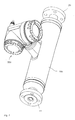
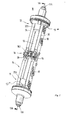
- FIG. 2 and 3 is an embodiment of one as a sensor 10th serving physical-electrical transducer assembly of the vibration type shown.
- the construction of such a converter arrangement is e.g. in the US-A 60 06 609 described in detail.
- Sensor already in standard Coriolis mass flow / Density meters used, e.g. also by the applicant itself the "PROMASS l" series.
- the measuring sensor 10 comprises at least one having an inlet end 11 and an outlet end 12 Measuring tube 13 of predeterminable, elastically deformable measuring tube lumens 13A and of predefinable nominal size.
- Elastic deformation of the measuring tube lumen 13A means here that to generate internal fluid and thus the fluid descriptive reaction forces, namely shear or Frictional forces, but also Coriolis forces and / or Inertial forces, a spatial shape in the operation of the sensor 10 and / or a spatial position of the measuring tube lumen 13A within a Range of elasticity of the measuring tube 13 cyclically in a predetermined manner, esp. periodically, is changed, cf. e.g. US-A 48 01 897, US-A 56 48 616, US-A 57 96 011 and / or US-A 60 06 609.
- any of those already skilled in the art for Coriolis mass flow / density meters known sensor especially a those of the bending vibration type with exclusively or at least partially in a bending vibration mode vibrating, curved or straight Measuring tube, can be used.
- Other suitable embodiments for such transducer arrangements serving as sensors 10 are e.g. in the US-A 53 01 557, US-A 53 57 811, US-A 55 57 973, the US-A 56 02 345, US-A 56 48 616 or in US-A 57 96 011 in detail described, the disclosure of which as to the disclosure of this application is considered to belong.
- Furthermore, e.g. also known to the expert magnetic-inductive sensors or ultrasonic sensors be used.
- the material for the measuring tube 13, which is essentially straight here, is e.g. Titanium alloys particularly suitable. Instead of titanium alloys but also others for such, especially for curved, measuring tubes commonly used materials such as stainless steel, tantalum or Zirconium etc. can be used.
- the measuring tube 13 which communicates in the usual way via an inlet tube piece 13 + and an outlet tube piece 13 # with which the fluid supplying and discharging pipeline, is in a rigid, in particular flexurally and torsionally rigid, and preferably from a converter housing 100 enveloped support frame 14 clamped swinging.
- the measuring tube 13 and the inlet and outlet tube pieces 13 + , 13 # are preferably made in one piece by means of a single tubular semi-finished product; if necessary, they can of course also be in several pieces.
- the support frame 14 is fixed on the inlet pipe section 13 + by means of an inlet plate 213 and on the outlet pipe section 13 # by means of an outlet plate 223, the latter two of which are each pierced by corresponding extension pieces of the measuring tube 13. Furthermore, the support frame 14 has a first side plate 24 and a second side plate 34, which two side plates 24, 34 are fixed to the inlet plate 213 and to the outlet plate 223 in such a way that they are essentially parallel to and spaced from the measuring tube 13 are arranged, cf. 2 and 3. Thus, mutually facing side surfaces of the two side plates 24, 34 are also parallel to one another.
- a longitudinal rod 25 is on the side plates 24, 34 from Measuring tube 13 fixed at a distance, the vibrations of the measuring tube 13th balancing mass serves.
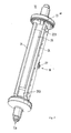
- the longitudinal bar 25 extends, as in FIG. 3 shown, practically parallel to the entire oscillatable length of the Measuring tube 13; however, this is not mandatory, the longitudinal bar 25 can of course, if necessary, be shorter.
- the support frame 14 with the two side plates 24, 34, the inlet plate 213, the outlet plate 223 and possibly the longitudinal rod 25 thus has one Longitudinal line of gravity substantially parallel to an inlet end 11 and the outlet end 12 extends virtually connecting measuring tube center axis 13B.
- the inlet pipe section 13 + is preferably formed with a first flange 19 and the outlet pipe section 13 # with a second flange 20, cf. Fig. 1;
- a second flange 20, cf. Fig. 1 instead of the flanges 19, 20, for example, so-called triclamp connections, as indicated in FIG. 2 or 3, can also be used for the detachable connection to the pipeline.
- the measuring tube 13 can also be connected directly to the pipeline, for example by welding or brazing etc.
- the measuring tube 13 is used to generate the above-mentioned reaction forces in the fluid in operation of the sensor 10, driven by one with the measuring tube coupled electro-mechanical excitation arrangement 16, at a Predeterminable oscillation frequency, especially one of a density, ⁇ , of the fluid dependent natural resonance frequency, in the so-called useful mode vibrate and thus elastically deformed in a predetermined way.
- the vibrating measuring tube 13 as in such transducer arrangements of the bending vibration type common from one static rest position spatially, esp. laterally, deflected; the same applies practically also for those transducer arrangements in which one or more curved Measuring tubes in operation are known to have a boom vibration corresponding, virtually connecting the respective inlet and outlet ends Longitudinal axis or for those in which one or more straight measuring tubes only execute plane bending vibrations around the longitudinal axis of the measuring tube.
- a transducer arrangement of the radial vibration type is used and the vibrating measuring tube is symmetrically deformed in the usual way the latter would essentially remain in its static rest position.
- the excitation arrangement 16 is used to generate an excitation force F exc acting on the measuring tube 13 by converting an electrical excitation power P exc which is fed in by the measuring device electronics.
- the excitation power P exc serves practically only to compensate for the power component extracted from the vibration system via mechanical and fluid-internal friction.
- the excitation power P exc is preferably set as precisely as possible so that essentially the vibrations of the measuring tube 13 in the useful mode, for example those with a lowest resonance frequency, are maintained.
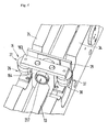
- the excitation arrangement 16 in the exemplary embodiment has a rigid, electromagnetically and / or electrodynamically driven lever arrangement 15 with a cantilever 154 fixed to the measuring tube 13 and with a yoke 163 on.
- the yoke 163 is also fixed to one end of the arm 154 at a distance from the measuring tube 13, in such a way that it is arranged above the measuring tube 13 and transversely to it.
- a metal disc, for example, which receives the measuring tube 13 in a bore can serve as the arm 154.
- The, here T-shaped, lever arrangement 15 is preferably, as can be seen in FIG. 2, arranged so that it acts approximately in the middle between the inlet and outlet ends 11, 12 on the measuring tube 13, which means that this is centered during operation performs its greatest lateral deflection.
- the excitation arrangement 16 For driving the lever arrangement 15, the excitation arrangement 16 4, a first excitation coil 26 and an associated first Permanent magnetic armature 27 and a second excitation coil 36 and one associated second permanent magnetic armature 37.
- the two, electrical preferably connected in series, excitation coils 26, 36 are on both sides of the Measuring tube 13 below the yoke 163 on the support frame 14, especially releasable, see above fixes that they with their respective anchor 27 and 37 in operation in Interact; otherwise the two excitation coils 26, 36, if necessary, of course, also be connected in parallel to each other.
- the two anchors 27, 37 are such from each other fixed at a distance to the yoke 163 that in operation of the sensor 10 the Armature 27 essentially from a magnetic field of the excitation coil 26 and Armature 37 essentially from a magnetic field of excitation coil 36 enforced and due to appropriate electrodynamic and / or electromagnetic force effects is moved.
- the movements generated by means of the magnetic fields of the excitation coils 26, 36 the armatures 27, 37 are placed on the measuring tube 13 via yoke 163 and bracket 154 transfer. These movements of the armature 27, 37 are designed so that the Yoke 163 alternately in the direction of the side plate 24 or in the direction of the Side plate 34 is deflected from its rest position.
- a corresponding, for already mentioned measuring tube center axis 13B parallel axis of rotation of the Lever arrangement 15 can e.g. through the boom 154.
- the support frame 14 further preferably comprises one with the side plates 24, 34, releasably, connected bracket 29 for the electromechanical Excitation arrangement 16.
- the measuring sensor of the exemplary embodiment in the measuring tube 13 due to a torque acting on this via lever arrangement 15 at the same time as the lateral deflections, at least in sections forced torsional rotation about the measuring tube central axis 13B, so that this practically in a mixed serving as utility fashion Bending vibration torsion mode swings.
- the rotation of the measuring tube 13 can be designed so that a lateral deflection of the measuring tube 13 spaced end of the boom 154 either the same or opposite is directed to the lateral deflection of the measuring tube 13.
- Measuring tube 13 can torsional vibrations in the former case corresponding first bending vibration torsion mode or in one of the latter case corresponding to the second bending vibration torsion mode execute, with the sensor 10 according to the embodiment natural resonance frequency of the second bending vibration torsion mode from e.g. 900 Hz is almost twice as high as that of the first Flexural and torsional mode.
- the measuring tube 13 vibrates operationally only in the second bending vibration torsion mode is in advantageously based on the eddy current principle Magnetic brake assembly 217 integrated into the excitation assembly 16, this serves to stabilize the position of this axis of rotation.
- the Magnetic brake assembly 217 can thus be ensured that the Measuring tube 13 always vibrates in the second bending vibration torsion mode thus any external interference on the measuring tube 13 does not become one spontaneous change to another, especially not in the first one, Lead bending vibration torsion mode.
- Details of such Magnetic brake arrangements are e.g. in detail in US-A 60 06 609 described; furthermore the use of such Magnetic brake arrangements already from sensors of the series mentioned "PROMASS l" known.
- the imaginary measuring tube center axis 13B is practically easily deformed and thus at the vibrations are not a plane but a slightly curved surface spans. Furthermore, one lying in this area points through the center the trajectory described the axis of the measuring tube the smallest curvature of all path curves described by the measuring tube center axis.
- the measuring sensor 10 further comprises a sensor arrangement 60 which, by means of at least one first sensor 17 which reacts to vibrations of the measuring tube 13, generates a first, in particular analog, sensor signal s 1 which represents this.
- the sensor 17 can, for example, as is customary in the case of such sensors, be formed by means of a permanent magnet armature fixed to the measuring tube 13 and interacting with a sensor coil held by the support frame 14.
- sensors 17 are those based on the electrodynamic principle, a speed of the deflections of the Detect the measuring tube.
- accelerometer electrodynamic or path-measuring resistive or optical Sensors are used.
- others can do that too Known to those skilled in the art and suitable for the detection of such vibrations Sensors are used.
- the sensor arrangement 60 further comprises a second sensor 18, in particular identical to the first sensor 17, by means of which it supplies a second sensor signal s 2 , which also represents vibrations of the measuring tube.
- the two sensors 17, 18 are spaced apart from one another along the measuring tube 13, in particular also at an equal distance from the center of the measuring tube 13, in the measuring sensor 10 so that by means of the sensor arrangement 60 both the inlet-side and outlet-side vibrations of the measuring tube 13 recorded locally and mapped into the corresponding sensor signals s 1 and s 2 .
- the first and possibly the second sensor signal s 1 or s 2 which usually each have a signal frequency corresponding to the instantaneous oscillation frequency of the measuring tube 13, are fed to the measuring device electronics, not shown here.
- the excitation arrangement 16 is fed by means of a likewise oscillating, unipolar or bi-polar excitation current i exc of adjustable amplitude and of an adjustable excitation frequency f exc supplied by the measuring device electronics in such a way that the excitation coils 26, 36 are in operation through which the magnetic fields required for moving the armatures 27, 37 are generated.
- the excitation force F exc required for vibrating the measuring tube 13 in the manner known to the person skilled in the art for example on the basis of the sensor signals s 1 or s 2 by means of a current and / or voltage control circuit, with regard to its amplitude and Control loop with regard to its frequency, can be monitored and adjusted.
- the excitation current i exc supplied by the measuring device electronics is preferably sinusoidal; however, it can also be, for example, a pulsating, a triangular or a rectangular alternating current.
- the excitation frequency f exc of the excitation current i exc corresponds, as is customary in the case of vibration measuring devices of the type described, to the predetermined oscillation frequency of the measuring tube 13 and is therefore preferably set to an instantaneous natural resonance frequency of the fluid-carrying measuring tube 13.
- an ultrasonic flow sensor is used as the measuring sensor, is an ultrasonic transducer in the manner known to those skilled in the art Excitation arrangement used, which, through which an excitation current flows, Coupled ultrasonic waves into the fluid in the measuring tube. Then also serves usually an ultrasonic transducer as a sensor arrangement, the Ultrasonic waves are coupled out of the fluid and into a corresponding one Measuring voltage converted.
- the sensor 10 shown in FIGS. 1 to 4 is practically a multivariable sensor with which, alternately or simultaneously, for example, the mass flow m is based on the two sensor signals s 1 , s 2 and / or the density ⁇ is based on the excitation frequency f exc and / or the viscosity, ⁇ , of the fluid can be detected on the basis of the excitation current i exc , the sensor signals, the excitation current or the above-mentioned measuring voltages are used in the following to further explain the invention in the sense of better uniformity and clarity under the term "Measurement signal" summarized.
- the measurement signal corresponding to the parameter to be measured for example the sensor signal s 1 or the excitation current i exc , depends to a considerable extent on an instantaneous density distribution in the fluid flowing in the measuring tube 13, but especially of a concentration and a distribution of possible parasitic inhomogeneities can be influenced.
- means are provided according to the invention in an inlet area of the measuring sensor 10 or at least in the vicinity thereof, which have a swirl in the inflowing fluid and thus in the fluid flowing within the measuring tube lumen a rotational movement relative to the measuring tube 13 around an imaginary axis of rotation lying in the direction of flow, which in the preferred case of a straight measuring tube practically coincides with the measuring tube center axis 13B.
- the means for effecting the swirl comprise at least one swirler 30 protruding into the flowing fluid.
- the swirler 30, which preferably rests in the tube lumen, can be, for example, a separate, propeller-shaped, helical or also helical component which, as in the FIGS 5a to d, at least partially in the inlet pipe section 13 + or, for example, at least partially directly in the measuring tube 13.
- the means for causing the swirl as shown in FIGS. 5a and 5b, are designed as a helical or also helical component, they can be held under mechanical tension in the inlet pipe section 13 + and / or the measuring pipe 13 inserted and thus held pressed against the respective inner wall by means of spring force.
- the means for generating the twist in particular the swirler 30 designed as a separate component, at least partially also within the pipeline supplying the fluid to the sensor 10 can be arranged. Furthermore, the means for generating the swirl e.g. also through a section of the pipeline that is angled several times be educated.
- the swirler 30 comprises at least one guide plate 30a protruding obliquely into the flowing fluid, in particular shaped in the manner of a turbine swirl vane.
- the swirler comprises two or more such baffles 30a, 30b, 30c, 30d, which, as indicated in FIG. 4d, are arranged in such a way that the swirler 30 is designed, for example in the manner of a turbine stator, as a stator.
- the at least one baffle plate 30a is preferably fixed to the inner wall of the inlet pipe section 13 + ; if necessary, however, it can also be attached to the inner wall of the pipeline supplying the fluid, for example.
- the means for effecting the swirl are designed in the manner of a drawn barrel as a train formed in the inner wall of the inlet pipe section 13 + and / or the measuring pipe 13.
- the means for causing the swirl should advantageously have an effective length in the direction of flow which is at least equal to a nominal diameter of the pipeline. Furthermore, particularly good measurement results could also be achieved if a reduction in the effective cross section of the inlet pipe section 13 + and / or the pipeline resulting from the installation of the swirler 30 was either kept very low or was compensated for by an increase in its respective nominal cross section.
- a particular advantage of the invention is the fact that the means for Effect the sensor using the twist practically in any Installation position, especially in the course of an essentially horizontal one Pipeline installed, with essentially constant measuring accuracy can be operated.
- Another advantage of the invention is that when it is applied to vibration-type sensors to vibrate the measuring tube 13, an excitation current i exc , which is considerably lower than that of conventional sensors, and thus less energy is required, especially with a high proportion of gaseous gases Inhomogeneities in the fluid to be measured.
Abstract
Description
Die Erfindung betriftt einen Meßaufnehmer sowie ein Verfahren zum Messen von wenigstens einem physikalischen Parameter, insb. eines Massedurchflusses und/oder einer Dichte und/oder einer Viskosität, eines in einer Rohrleitung strömenden, insb. mehrphasigen, Fluids.The invention relates to a sensor and a method for measuring of at least one physical parameter, especially one Mass flow and / or a density and / or a viscosity, one in a pipeline flowing, especially multi-phase, fluid.
In der Prozeßmeß- und Automatisierungstechnik werden für die Messung physikalischer Parameter eines in einer Rohrleitung strömenden Fluids, wie z.B. dem Massedurchfluß, der Dichte und/oder der Viskosität, oftmals solche Meßgeräte verwendet, die mittels eines vom Fluid durchströmten Meßaufnehmers vom Vibrationstyp und einer daran angeschlossenen Meß- und Betriebsschaltung, im Fluid Reaktionskräfte, wie z.B. mit dem Massedurchfluß korrespondierende Corioliskräfte, mit der Dichte korrespondierende Trägheitskräfte oder mit der Viskosität korrespondierende Reibungskräfte etc., bewirken und von diesen abgeleitet ein den jeweiligen Massedurchfluß, ein die jeweilige Vikosität und/oder ein die jeweilige Dichte des Fluids repräsentierendes Meßsignal erzeugen.In process measurement and automation technology are used for measurement physical parameters of a fluid flowing in a pipeline, e.g. the mass flow, density and / or viscosity, often such Measuring devices used by means of a fluid flowed through Vibration type sensor and a connected measuring and Operating circuit, in the fluid reaction forces, e.g. with the mass flow corresponding Coriolis forces, corresponding to the density Inertial forces or friction forces corresponding to viscosity, etc., effect and derived from these a respective mass flow, a respective viscosity and / or the respective density of the fluid generate representative measurement signal.
Derartige Meßaufnehmer vom Vibrationstyp sind z.B. in der WO-A 01/33 174, der WO-A 00/57 141, der WO-A 98/07 009, der WO-A 95/16 897, der WO-A 88/03 261, der US-A 60 06 609, der US-A 57 96 011, der US-A 53 01 557, der US-A 48 76 898, der US-A 45 24 610, der EP-A 553 939 oder der EP-A 1 001 254 beschrieben.Such vibration type sensors are e.g. in WO-A 01/33 174, WO-A 00/57 141, WO-A 98/07 009, WO-A 95/16 897, the WO-A 88/03 261, US-A 60 06 609, US-A 57 96 011, the US-A 53 01 557, US-A 48 76 898, US-A 45 24 610, EP-A 553 939 or EP-A 1 001 254.
Zum Führen des Fluids umfassen die Meßaufnehmer jeweils mindestens ein in einem Trägerrahmen gehaltertes Meßrohr mit einem gebogenen oder geraden Rohrsegment, das zum Erzeugen oben genannter Reaktionskräfte, angetrieben von einer elektromechanischen Erregeranordnung, im Betrieb vibrieren gelassen wird. Zum Erfassen, insb. einlaßseitger und auslaßseitiger, Vibrationen des Rohrsegments weisen die Meßaufnehmer ferner jeweils eine auf Bewegungen des Rohrsegments reagierende Sensoranordnung auf.To guide the fluid, the sensors each include at least one in a measuring tube supported with a curved or straight measuring frame Pipe segment, which is used to generate the above-mentioned reaction forces from an electromechanical excitation arrangement, vibrate during operation is left. For detection, especially on the inlet and outlet side, Vibrations of the pipe segment each have a sensor sensor arrangement reacting to movements of the pipe segment.
Neben derartigen Meßaufnehmern vom Vibrationstyp werden in der Prozeßmeß- und Automatisierungstechnik für die In-Line-Messungen häufig auch Meßgeräte mit magnetisch-induktiven Meßaufnehmern oder mit Ultraschall-Meßaufnehmern eingesetzt. Da der prinzipielle Aufbau und die Funktionsweise solcher magnetisch-induktiven Meßaufnehmer z.B. in der EP-A 1 039 269, US-A 60 31 740, US-A 55 40 103, US-A 53 51 554, US-A 45 63 904 etc. oder solcher Ultraschall-Meßaufnehmer z.B. US-B 63 30 831, US-B 62 93 156, US-A 51 31 279, US-A 47 87 252 etc. hinlänglich beschrieben sind, kann an dieser Stelle auf eine detailliertere Erläuterung verzichtet werden.In addition to such sensors of the vibration type in the Process measurement and automation technology for in-line measurements often also measuring devices with magnetic-inductive sensors or with Ultrasonic sensors used. Since the basic structure and the Operation of such magnetic-inductive sensors e.g. in the EP-A 1 039 269, US-A 60 31 740, US-A 55 40 103, US-A 53 51 554, US-A 45 63 904 etc. or such ultrasonic sensor e.g. US-B 63 30 831, US-B 62 93 156, US-A 51 31 279, US-A 47 87 252 etc. are sufficiently described at this point to a more detailed Explanation to be dispensed with.
Bei der Verwendung von In-Line-Meßaufnehmern der beschriebenen Art hat es sich jedoch gezeigt, daß bei inhomogenen Fluiden, insb. mehrphasigen Fluiden, die dort erzeugten Meßsignale trotz, insb. auch unter Laborbedingungen, praktisch konstantgehaltener Viskosität und Dichte in erheblichem Maße nicht reproduzierbaren Schwankungen unterliegen und somit für die Messung des jeweiligen physikalischen Parameters praktisch unbrauchbar werden können.When using in-line sensors of the type described, it has However, it has been shown that inhomogeneous fluids, in particular multiphase fluids, the measurement signals generated there despite, especially under laboratory conditions, viscosity and density, which are kept practically constant, to a considerable extent not subject to reproducible fluctuations and thus for the measurement of the respective physical parameters can become practically unusable.
In der US-A 45 24 610 wird bereits eine mögliche Ursache dieses Problems für den Betrieb von Vibrationstyp-Meßaufnehmern angedeutet, nämlich der Umstand, daß sich vom Fluid in das Meßrohr eingetragene parasitäre Inhomogenitäten, wie z.B. Gasblasen, an dessen Innenwand anlagern können. Zur Umgehung des Problems wird ferner vorgeschlagen, den Meßaufnehmer so einzubauen, daß das gerade Meßrohr im wesentlichen senkrecht verläuft und somit ein Anlagern solcher parasitärer, insb. gasförmiger, Inhomogenitäten verhindert wird. Hierbei handelt es sich jedoch um eine sehr spezielle und, insb. in der industriellen Prozeßmeßtechnik, nur sehr bedingt realisierbare Lösung. Zum einen müßte nämlich für diesen Fall die Rohrleitung, in die der Meßaufnehmer eingefügt werden soll, ggf. an diesen angepaßt werden und nicht umgekehrt, was dem Anwender wohl eher nicht zu vermitteln ist. Zum anderen kann es sich bei den Meßrohren, wie bereits erwähnt, auch um solche mit einer gekrümmten Rohrform handeln, so daß das Problem auch durch eine Anpassung der Einbaulage nicht gelöst werden kann. Es hat sich hierbei außerdem gezeigt, daß die vorgenannten Verfälschungen des Meßsignals auch bei Verwendung eines senkrecht eingebauten, geraden Meßrohrs nicht wesentlich verringert werden können. Außerdem lassen sich die im weiteren festgestellten Schwankungen des so erzeugten Meßsignals bei strömendem Fluid auf diese Weise ebenfalls nicht verhindern.In US-A 45 24 610 there is already a possible cause of this problem the operation of vibration type sensors indicated, namely the Circumstances that parasitic introduced by the fluid into the measuring tube Inhomogeneities, e.g. Gas bubbles, can accumulate on the inner wall. To circumvent the problem, the sensor is also proposed to be installed so that the straight measuring tube is essentially vertical and thus an accumulation of such parasitic, especially gaseous, inhomogeneities is prevented. However, this is a very special and, esp. in industrial process measurement technology, only a very limited feasible solution. For one thing, the pipeline in which the Sensor is to be inserted, if necessary adapted to this and not the other way round, which is probably not something the user can get across. To the others, as already mentioned, can also be such in the measuring tubes act with a curved tube shape, so that the problem through a Adjustment of the installation position cannot be solved. It has been here also shown that the aforementioned falsifications of the measurement signal also not when using a vertically installed, straight measuring tube can be significantly reduced. In addition, the fluctuations of the measurement signal thus generated when flowing Do not prevent fluid in this way either.
Eine Aufgabe der Erfindung besteht daher darin, ein Verfahren sowie einen Meßaufnehmer anzugeben, das bzw. der auch bei inhomogenen, insb. mehrphasigen, Fluiden möglichst unabhängig von der momentanen Dichteverteilung innerhalb des in der angeschlossenen Rohrleitung strömenden Fluids, insb. aber auch weitgehend unabhängig von der Konzentration allfälliger parasitärer Inhomogenitäten, und auch möglichst unabhängig von der Einbaulage des Meßrohrs genaue, zumindest aber gut reproduzierbare und weitgehend robuste Meßsignale liefert.An object of the invention is therefore a method and a Specify sensor that also with inhomogeneous, esp. multiphase, fluids as independent of the momentary as possible Density distribution within the flowing in the connected pipeline Fluids, especially but largely independent of the concentration of any parasitic inhomogeneities, and also as independent of the Installation position of the measuring tube accurate, but at least reproducible and delivers largely robust measurement signals.
Zur Lösung der Aufgabe besteht die Erfindung in einem Verfahren zum Messen von wenigstens einem physikalischen Parameter, insb. eines Massedurchflusses und/oder einer Dichte und/oder einer Viskosität, eines in einer Rohrleitung strömenden Fluids, welches Verfahren folgende Schritte umfaßt:
- Bewirken eines Dralls im strömenden Fluid um eine mit einer Strömungsrichtung fluchtende Drallachse zum Erzwingen einer zur Drallachse möglichst rotationssymmetrischen Dichteverteilung im Fluid,
- Strömenlassen des um die Drallachse rotierenden Fluids durch wenigstens ein Meßrohr eines in die Rohrleitung eingefügten Meßaufnehmers zum Erzeugen von mit dem zu messenden Parameter korrespondierenden Reaktionen im Fluid sowie
- Erfassen von Reaktionen im Fluid zum Erzeugen wenigstens eines vom zu messenden Parameter beeinflußten Meßsignals.
- Effecting a swirl in the flowing fluid around a swirl axis aligned with a direction of flow to force a density distribution in the fluid that is as rotationally symmetrical as possible with respect to the swirl axis,
- Allowing the fluid rotating about the swirl axis to flow through at least one measuring tube of a measuring sensor inserted into the pipeline for generating reactions in the fluid corresponding to the parameter to be measured and
- Detection of reactions in the fluid to generate at least one measurement signal influenced by the parameter to be measured.
Des weiteren besteht die Erfindung in einem Meßaufnehmer zum Erzeugen eines Meßsignals, das mit wenigstens einem physikalischen Parameter eines in einer Rohrleitung strömenden Fluids korrespondiert, welcher Meßaufnehmer umfaßt:
- wenigstens ein Meßrohr zum Führen des Fluids, welches Meßrohr einlaßseitig und auslaßseitig mit der Rohrleitung kommuniziert und
- eine Erregeranordnung zum Bewirken von sensorisch erfaßbaren Reaktionen im Fluid innerhalb des wenigstens einen Meßrohrs sowie
- eine Sensoranordnung zum Erfassen der Reaktionen im Fluid und zum Erzeugen des Meßsignals,
- wobei in einem Einlaßbereich des Meßaufnehmers oder zumindest in dessen Nähe Mittel vorgesehen sind, die einen Drall im einströmenden Fluid und somit im innerhalb des Meßrohrlumens strömenden Fluid eine Rotationsbewegung relativ zum Meßrohr um eine in Strömungsrichtung liegende imaginäre Rotationsachse bewirken.
- at least one measuring tube for guiding the fluid, which measuring tube communicates with the pipeline on the inlet side and on the outlet side and
- an exciter arrangement for causing sensor-detectable reactions in the fluid within the at least one measuring tube and
- a sensor arrangement for detecting the reactions in the fluid and for generating the measurement signal,
- wherein means are provided in an inlet area of the measuring sensor or at least in the vicinity thereof, which cause a swirl in the inflowing fluid and thus in the fluid flowing within the measuring tube lumen a rotational movement relative to the measuring tube about an imaginary axis of rotation lying in the flow direction.
Außerdem besteht die Erfindung in einem Meßgerät zum Messen wenigstens eines physikalischen Parameters eines in einer Rohrleitung strömenden Fluids, insb. geeignet zur Realisierung des erfindungsgemäßen Verfahrens mit einem solchen Meßaufnehmer.In addition, the invention consists in a measuring device for measuring at least a physical parameter of a fluid flowing in a pipeline, especially suitable for implementing the method according to the invention with a such a sensor.
Nach einer bevorzugten Ausgestaltung des Verfahrens der Erfindung wird das Fluid führende Meßrohr zum Erzeugen von mit dem zu messenden Parameter korrespondierenden, auf das vibrierende Meßrohr zurückwirkenden Reaktionskräften im zu messenden Fluid vibrierengelassen und werden Vibrationen des Meßrohrs zum Erzeugen des wenigstens einen Meßsignals erfaßt.According to a preferred embodiment of the method of the invention Fluid-carrying measuring tube for generating with the parameter to be measured corresponding, reacting on the vibrating measuring tube Reaction forces are vibrated in the fluid to be measured and are Vibrations of the measuring tube for generating the at least one measuring signal detected.
Nach einer bevorzugten ersten Ausgestaltung des Meßaufnehmers der Erfindung kommuniziert das wenigstens eine Meßrohr über ein einlaßseitiges Einlaßrohrstück und über ein auslaßseitiges Auslaßrohrstück mit der Rohrleitung und sind die Mittel zum Bewirken des Dralls zumindest anteilig innerhalb des Einlaßrohrstücks angeordnet. According to a preferred first embodiment of the sensor Invention communicates the at least one measuring tube via an inlet side Inlet pipe section and via an outlet-side outlet pipe section with the Pipeline and are the means for causing the swirl at least partially arranged within the inlet pipe section.
Nach einer bevorzugten zweiten Ausgestaltung des Meßaufnehmers der Erfindung sind die Mittel zum Bewirken des Dralls zumindest anteilig innerhalb des wenigstens einen Meßrohrs angeordnet.According to a preferred second embodiment of the sensor Invention are the means for effecting the twist at least partially within of the at least one measuring tube.
Nach einer bevorzugten dritten Ausgestaltung des Meßaufnehmers der Erfindung sind die Mittel zum Bewirken des Dralls zumindest anteilig innerhalb der Rohrleitung angeordnet.According to a preferred third embodiment of the sensor Invention are the means for effecting the twist at least partially within the pipeline.
Nach einer bevorzugten vierten Ausgestaltung des Meßaufnehmers der Erfindung umfassen die Mittel zum Bewirken des Dralls wenigstens einen in das strömende Fluid hineinragenden, insb. ruhenden, Verwirbler.According to a preferred fourth embodiment of the sensor Invention comprise the means for causing the twist at least one in the flowing fluid protruding, especially resting, swirler.
Nach einer bevorzugten fünften Ausgestaltung des Meßaufnehmers der Erfindung umfaßt der Verwirbler wenigstens ein in das strömende Fluid hineinragendes Leitblech.According to a preferred fifth embodiment of the sensor Invention, the swirler includes at least one fluid flowing into the fluid protruding baffle.
Nach einer bevorzugten sechsten Ausgestaltung des Meßaufnehmers der Erfindung ist der Verwirbler propellerförmig ausgebildet.According to a preferred sixth embodiment of the sensor Invention, the swirler is propeller-shaped.
Nach einer bevorzugten siebenten Ausgestaltung des Meßaufnehmers der Erfindung ist der Verwirbler helixförmig ausgebildet.According to a preferred seventh embodiment of the sensor Invention, the swirler is helical.
Nach einer bevorzugten achten Ausgestaltung des Meßaufnehmers der Erfindung ist der Verwirbler schneckenförmig ausgebildet.According to a preferred eighth embodiment of the sensor Invention, the swirler is helical.
Nach einer bevorzugten neunten Ausgestaltung des Meßaufnehmers der Erfindung sind die Mittel zum Bewirken des Dralls an der Innenwand des Einlaßrohrstücks und/oder an der Innenwand des Meßrohrs fixiert.According to a preferred ninth embodiment of the sensor Invention are the means of causing the twist on the inner wall of the Inlet pipe section and / or fixed to the inner wall of the measuring tube.
Nach einer bevorzugten zehnten Ausgestaltung des Meßaufnehmers der Erfindung sind die Mittel zum Bewirken des Dralls gegen die Innenwand des Einlaßrohrstücks und/oder die Innenwand des Meßrohrs gedrückt gehalten. According to a preferred tenth embodiment of the sensor Invention are the means of causing the twist against the inner wall of the Inlet pipe section and / or the inner wall of the measuring tube kept pressed.
Nach einer bevorzugten elften Ausgestaltung des Meßaufnehmers der Erfindung sind die Mittel zum Bewirken des Dralls als in die Innenwand des Einlaßrohrstücks und/oder in die Innenwand des Meßrohrs eingeformter Zug ausgebildet.According to a preferred eleventh embodiment of the sensor Invention are the means to effect the swirl as in the inner wall of the Inlet pipe section and / or train molded into the inner wall of the measuring tube educated.
Nach einer bevorzugten zwölften Ausgestaltung des Meßaufnehmers der Erfindung weisen die Mittel zum Bewirken des Dralls in Strömungsrichtung eine wirksame Länge auf, die mindestens gleich einer Nennweite der Rohrleitung ist.According to a preferred twelfth embodiment of the sensor Invention have the means for causing the swirl in the direction of flow effective length that is at least equal to a nominal diameter of the pipeline.
Nach einer bevorzugten dreizehnten Ausgestaltung der Erfindung ist der Meßaufnehmer in den Verlauf einer im wesentlichen waagerechten Rohrleitung eingebaut.According to a preferred thirteenth embodiment of the invention Sensor in the course of an essentially horizontal pipeline built-in.
Nach einer bevorzugten vierzehnten Ausgestaltung der Erfindung ist der Meßaufnehmer in den Verlauf einer im wesentlichen senkrechten Rohrleitung eingebaut.According to a preferred fourteenth embodiment of the invention Sensor in the course of an essentially vertical pipeline built-in.
Nach einer bevorzugten fünfzehnten Ausgestaltung des Meßaufnehmers der Erfindung wird das wenigstens eine Meßrohr im Betrieb zum Erzeugen von im Fluid wirkenden Reaktionskräften mittels der Erregeranordnung vibrierengelassen und werden mittels der Sensoranordnung Vibrationen des Meßrohrs erfaßt.According to a preferred fifteenth embodiment of the sensor Invention is the at least one measuring tube in operation for generating in Fluid acting reaction forces by means of the excitation arrangement vibrated and are vibrations by means of the sensor arrangement Measuring tube detected.
Nach einer bevorzugten ersten Ausgestaltung des Meßgeräts der Erfindung ist der zu messende physikalische Parameter ein Massendurchfluß.According to a preferred first embodiment of the measuring device of the invention the physical parameter to be measured is a mass flow.
Nach einer bevorzugten zweiten Ausgestaltung des Meßgeräts der Erfindung ist der zu messende physikalische Parameter eine Dichte.According to a preferred second embodiment of the measuring device of the invention the physical parameter to be measured is a density.
Nach einer bevorzugten dritten Ausgestaltung des Meßgeräts der Erfindung ist der zu messende physikalische Parameter eine Viskosität. According to a preferred third embodiment of the measuring device of the invention the physical parameter to be measured is a viscosity.
Ein Grundgedanke der Erfindung besteht darin, mittels der Rotationsbewegung um die Drallachse im Fluid Zentrifugalkräfte zu induzieren, die so ausgebildet sind, daß zumindest innerhalb des Meßrohrlumens eine bezüglich der Drallachse der rotierenden "Fluidsäule" möglichst rotationssymmetrische und somit weitgehend reproduzierbare Dichteverteilung erzwungen wird. Eine allfällige geringe Verfälschung im Meßergebnis, insb. im Dichte-Meßwert, die vor allem bei Flüssigkeiten mit parasitären gasförmigen Inhomogenitäten aufgrund der dann aus den Zentrifugalkräften resultierenden Konzentration solcher Gaseinschlüsse im Zentrum des Meßrohrlumens zu erwarten ist, kann im Vergleich zu den vorbeschriebenen nicht reproduzierbaren Schwankungen durchaus als vernachlässigbar klein eingeschätzt werden.A basic idea of the invention is by means of the rotational movement to induce the swirl axis in the fluid centrifugal forces that are formed are that at least within the measuring tube lumen with respect to the Swirl axis of the rotating "fluid column" as rotationally symmetrical and possible thus largely reproducible density distribution is enforced. A any slight falsification in the measurement result, especially in the density measurement value, the especially with liquids with parasitic gaseous inhomogeneities due to the concentration resulting from the centrifugal forces such gas inclusions in the center of the measuring tube lumen can be expected compared to the non-reproducible fluctuations described above be considered negligible.
Die Erfindung beruht dabei insb. auch auf der Erkenntnis, daß die oben beschriebenen Schwankungen der Meßsignale nicht allein darauf zurückzuführen sind, daß sich z.B. Gasblasen an der Innenwand des Meßrohrs anlagern, sondern insb. darauf, daß dies im wesentlichen chaotisch und somit praktisch nicht reproduzierbar oder vorhersagbar erfolgt. Anders gesagt, die Schwankungen der Meßsignale bei der Verwendung herkömmlicher Meßaufnehmer mit geraden oder schwach gebogenen Meßrohren für inhomogene, insb. mehrphasige, Fluide können in einem erheblichen Maße auf die im wesentlichen chaotische Verteilung von Inhomogenitäten im Fluid, wie z.B. allfällig eingeperlte Gasblasen, und daraus resultierend auf eine sich stets ändernde jedoch praktisch nicht detektierbare Dichteverteilung innerhalb des Fluids im Meßrohrlumen zurückgeführt werden.The invention is based in particular on the knowledge that the above fluctuations in the measurement signals described are not solely based thereon are due to the fact that e.g. Gas bubbles on the inner wall of the measuring tube attach, but especially that this is essentially chaotic and thus is practically not reproducible or predictable. In other words, the Fluctuations in the measurement signals when using conventional Sensor with straight or slightly curved measuring tubes for inhomogeneous, esp. multiphase, fluids can to a considerable extent the essentially chaotic distribution of inhomogeneities in the fluid, such as e.g. any bubbled-in gas bubbles, and the result is always one changing but practically undetectable density distribution within the Fluids in the measuring tube lumen are returned.
Ein Vorteil des Erfindung, insb. auch des erfindungsgemäßen Verfahrens, besteht darin, daß es praktisch für alle bekannten In-Line-Meßaufnehmer, insb. auch alle Durchflußmeßprinzipien, angewendet werden und dementsprechend sowohl in Meßaufnehmern vom Vibrationstyp als auch z.B. in magnetisch-induktive Meßaufnehmer oder in Ultraschall-Meßaufnehmer eingesetzt werden kann. An advantage of the invention, especially the method according to the invention, is that it is practically for all known in-line sensors, esp. also all flow measurement principles are applied and accordingly both in vibration-type sensors and e.g. in magnetic-inductive Sensor or be used in ultrasonic sensors can.
Die Erfindung und weitere Vorteile werden nachfolgend anhand von Ausführungsbeispielen näher erläutert, die in den Figuren der Zeichnung dargestellt sind; gleiche Teile sind in den Figuren mit gleichen Bezugszeichen versehen. Falls es der Übersichtlichkeit dienlich ist, wird auf die Angabe bereits vergebener Bezugszeichen in nachfolgenden Figuren verzichtet.
- Fig. 1
- zeigt in einer Seitenansicht ein Meßgerät zum Messen wenigstens eines physikalischen Parameters eines in einer Rohrleitung strömenden Fluids,
- Fig. 2
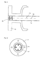
- zeigt perspektivisch in einer ersten Seitenansicht ein Ausführungsbeispiel eines für das Meßgerät von Fig. 1 geeigneten Meßaufnehmers vom Vibrations-Typ,
- Fig. 3
- zeigt den Meßaufnehmer von Fig. 3 perspektivisch in einer zweiten Seitenansicht,
- Fig. 4
- zeigt ein Ausführungsbeispiel einer für den Meßaufnehmer von Fig. 2 und 3 geeigneten elektro-mechanischen Erregeranordnung und
- Fig. 5a
- zeigt Ausgestaltungen erfindungsgemäßer Mittel zum
- bis 5d
- Bewirken eines Dralls im zu messenden Fluid.
- Fig. 1
- shows a side view of a measuring device for measuring at least one physical parameter of a fluid flowing in a pipeline,
- Fig. 2
- 1 shows, in perspective, a first side view of an embodiment of a vibration-type measuring sensor suitable for the measuring device of FIG. 1,
- Fig. 3
- 3 shows the sensor of FIG. 3 in perspective in a second side view,
- Fig. 4
- shows an embodiment of a suitable for the sensor of FIGS. 2 and 3 electro-mechanical excitation arrangement and
- Fig. 5a
- shows embodiments of inventive means for
- to 5d
- Causing a swirl in the fluid to be measured.
In der Fig. 1 ist ein Meßgerät mit einem, bevorzugt in einem Wandlergehäuse
100 untergebrachten, Meßaufnehmer 10 sowie einer - hier nicht gezeigten - in
einem Elektronikgehäuse 200 untergebrachten und mit dem Meßaufnehmer 10
elektrisch verbundenen Meßgerät-Elektronik schematisch dargestellt. Das
Meßgerät dient insb. dazu, einen physikalischen Parameter eines in einer, hier
nicht gezeigten, Rohrleitung strömenden Fluids, insb. einen Massedurchfluß m
und/oder eine Dichte p und/oder eine Viskosität, η, zu erfassen und in einen
diesen Parameter momentan repräsentierenden Meßwert abzubilden. Ferner
kann das Meßgerät aber z.B. auch dazu dienen, ein Volumenstrom des Fluids
zu messen.In Fig. 1 is a measuring device with one, preferably in a
Zu diesem Zweck werden im Betrieb mittels des von der Meßgerät-Elektronik
angetriebenen Meßaufnehmers 10 im hindurchströmenden Fluid solche
Reaktionen erzeugt, die vom zu messenden Parameter abhängig sind und die
meßbar, also sensorisch erfaßbar und elektronisch auswertbar, auf den
Meßaufnehmer 10 zurückwirken. Solche Reaktionen können z.B.
volumenstromabhängige magnetisch-induktiv erzeugte elektrische
Spannungen, massedurchflußabhängige Corioliskräfte, dichteabhängige
Massenträgheitskräfte und/oder viskositätsabhängige Reibungs- oder auch
Dämpfungskräfte etc. sein.For this purpose, in operation by means of the measuring device electronics
driven
Für den bevorzugten Fall, daß das Meßgerät für eine Ankopplung an einen Feldbus vorgesehen ist, weist die, insb. programmierbare, Meßgerät-Elektronik eine entsprechende Kommunikations-Schnittstelle für eine Datenkommunikation auf, z.B. zum Senden der Meßdaten an eine übergeordnete speicherprogrammierbare Steuerung oder ein übergeordnetes Prozeßleitsystem, auf.For the preferred case that the measuring device for coupling to a Fieldbus is provided, especially the programmable measuring device electronics a corresponding communication interface for a Data communication, e.g. to send the measurement data to a higher-level programmable logic controller or a higher-level Process control system, on.
In den Fig. 2 und 3 ist ein Ausführungsbeispiel einer als ein Meßaufnehmer 10 dienenden physikalisch-elektrischen Wandleranordnung vom Vibrationstyp gezeigt. Der Aufbau einer derartigen Wandleranordnung ist z.B. in der US-A 60 06 609 ausführlich beschrieben. Ferner werden derartige Meßaufnehmer bereits in marktüblichen Coriolis-Massedurchfluß/ Dichtemeßgeräten verwendet, wie sie z.B. auch von der Anmelderin selbst mit der Serie "PROMASS l" angeboten werden.2 and 3 is an embodiment of one as a sensor 10th serving physical-electrical transducer assembly of the vibration type shown. The construction of such a converter arrangement is e.g. in the US-A 60 06 609 described in detail. Furthermore, such Sensor already in standard Coriolis mass flow / Density meters used, e.g. also by the applicant itself the "PROMASS l" series.
Zum Führen des zu messenden Fluids umfaßt der Meßaufnehmer 10
wenigstens ein ein Einlaßende 11 und ein Auslaßende 12 aufweisendes
Meßrohr 13 von vorgebbarem, elastisch verformbaren Meßrohrlumen 13A und
von vorgebbarer Nennweite. Elastisches Verformen des Meßrohrlumens 13A
bedeutet hier, daß zum Erzeugen von fluidinternen und somit das Fluid
beschreibenden Reaktionskräften, nämlich von Scher- oder auch
Reibungskräften, aber auch von Corioliskräften und/oder
Masseträgheitskräften, im Betrieb des Meßaufnehmers 10 eine Raumform
und/oder eine Raumlage des Meßrohrlumens 13A innerhalb eines
Elastizitätsbereiches des Meßrohrs 13 in vorgebbarer Weise zyklisch, insb.
periodisch, verändert wird, vgl. z.B. die US-A 48 01 897, die US-A 56 48 616,
die US-A 57 96 011 und/oder die US-A 60 06 609.To guide the fluid to be measured, the measuring
Es sei an dieser Stelle darauf verwiesen, daß zur Realisierung der Erfindung
anstelle eines Meßaufnehmers gemäß dem Ausführungsbeispiel von Fig. 2 und
3 praktisch jeder der dem Fachmann bereits für Coriolis-Massedurchfluß/Dichtemeßgeräte
bekannten Meßaufnehmer, insb. auch ein
solcher vom Biegeschwingungstyp mit ausschließlich oder zumindest anteilig in
einem Biegeschwingungsmode vibrierendem, gebogenem oder geradem
Meßrohr, verwendet werden kann. Weitere geeignete Ausführungsformen für
solche als Meßaufnehmer 10 dienende Wandleranordnungen sind z.B. in der
US-A 53 01 557, der US-A 53 57 811, der US-A 55 57 973, der
US-A 56 02 345, der US-A 56 48 616 oder in der US-A 57 96 011 ausführlich
beschrieben, deren Offenbarung als zur Offenbarung dieser Anmeldung
zugehörig erachtet wird. Ferner können z.B. auch dem Fachmann bekannte
magnetisch-induktive Meßaufnehmer oder auch Ultraschall-Meßaufnehmer
verwendet werden.At this point, it should be noted that to implement the invention
instead of a sensor according to the embodiment of FIGS. 2 and
3 virtually any of those already skilled in the art for Coriolis mass flow / density meters
known sensor, especially a
those of the bending vibration type with exclusively or at least partially in
a bending vibration mode vibrating, curved or straight
Measuring tube, can be used. Other suitable embodiments for
such transducer arrangements serving as
Als Material für das, hier im wesentlichen gerade, Meßrohr 13 sind z.B.
Titanlegierungen besonders geeignet. Anstelle von Titanlegierungen können
aber auch andere für derartige, insb. auch für gebogene, Meßrohre
üblicherweise verwendete Materialien wie z.B. rostfreier Stahl, Tantal oder
Zirconium etc. verwendet werden.The material for the measuring
Das Meßrohr 13, welches in der üblichen Weise über ein Einlaßrohrstück 13+
und über ein Auslaßrohrstück 13# mit der das Fluid zu- bzw. abführende
Rohrleitung kommuniziert, ist in einen starren, insb. biege- und
verwindungssteifen, und bevorzugt von einem Wandlergehäuse 100 umhüllten
Tragrahmen 14 schwingfähig eingespannt. Das Meßrohr 13 sowie das Einlaßund
das Auslaßrohrstück 13+, 13# sind bevorzugt einstückig mittels eines
einzigen rohrförmigen Halbzeugs gefertigt; falls erforderlich können sie
selbstverständlich auch mehrstückig sein.The measuring
Der Tragrahmen 14 ist am Einlaßrohrstück 13+ mittels einer Einlaßplatte 213
und am Auslaßrohrstück 13# mittels einer Auslaßplatte 223 fixiert, wobei
letztere beiden jeweils von entsprechenden Verlängerungsstücken des
Meßrohrs 13 durchstoßen sind. Des weiteren weist der Tragrahmen 14 eine
erste Seitenplatte 24 und eine zweite Seitenplatte 34 auf, welche beiden
Seitenplatten 24, 34 derart an der Einlaßplatte 213 und an der Auslaßplatte 223
fixiert sind, daß sie im wesentlichen parallel zum Meßrohr 13 sowie von diesem
und voneinander beabstandet angeordnet sind, vgl. Fig. 2 und 3. Somit sind
einander zugewandte Seitenflächen der beiden Seitenplatten 24, 34 ebenfalls
parallel zueinander.The
In vorteilhafter Weise ist ein Längsstab 25 an den Seitenplatten 24, 34 vom
Meßrohr 13 beabstandet fixiert, der als Schwingungen des Meßrohrs 13
tilgende Auswuchtmasse dient. Der Längstab 25 erstreckt sich, wie in Fig. 3
dargestellt, praktisch parallel zur gesamten schwingfähigen Länge des
Meßrohrs 13; dies ist jedoch nicht zwingend, der Längstab 25 kann
selbstverständlich, falls erforderlich, auch kürzer ausgeführt sein.Advantageously, a
Der Tragrahmen 14 mit den beiden Seitenplatten 24, 34, der Einlaßplatte 213,
der Auslaßplatte 223 und ggf. dem Längsstab 25 hat somit eine
Längsschwerelinie, die im wesentlichen parallel zu einer das Einlaßende 11 und
das Auslaßende 12 virtuell verbindenden Meßrohrmittelachse 13B verläuft.The
In den Fig. 2 und 3 ist durch die Köpfe der gezeichneten Schrauben
angedeutet, dass das erwähnte Fixieren der Seitenplatten 24, 34 an der
Einlaßplatte 213, an der Auslaßplatte 223 und am Längsstab 25 durch
Verschrauben erfolgen kann; es können aber auch andere geeignete und dem
Fachmann geläufige Befestigungsarten angewendet werden. 2 and 3 is by the heads of the drawn screws
indicated that the aforementioned fixing of the
Für den Fall, daß der Meßaufnehmer 10 lösbar mit der Rohrleitung zu
montieren ist, ist dem Einlaßrohrstück 13+ bevorzugt ein erster Flansch 19 und
dem Auslaßrohrstück 13# ein zweiter Flansch 20 angeformt, vgl. Fig. 1; anstelle
der Flansche 19, 20 können aber z.B. auch sogenannte, wie in Fig. 2 oder 3
angedeutet, Triclamp-Anschlüsse zur lösbaren Verbindung mit der Rohrleitung
dienen. Falls erforderlich kann das Meßrohr 13 aber auch direkt mit der
Rohrleitung, z.B. mittels Schweißen oder Hartlötung etc.In the event that the
Zum Erzeugen oben genannter Reaktionskräfte im Fluid wird das Meßrohr 13
im Betrieb des Meßaufnehmers 10, angetrieben von einer mit dem Meßrohr
gekoppelten elektro-mechanischen Erregeranordnung 16, bei einer
vorgebbaren Schwingfrequenz, insb. einer auch von einer Dichte, ρ, des Fluids
abhängigen natürlichen Resonanzfrequenz, im sogenannten Nutzmode
vibrieren gelassen und somit in vorgebbarer Weise elastisch verformt.The measuring
Im gezeigten Ausführungsbeispiel wird das vibrierende Meßrohr 13, wie bei
solchen Wandleranordnungen vom Biegeschwingungs-Typ üblich, aus einer
statischen Ruhelage räumlich, insb. lateral, ausgelenkt; gleiches gilt praktisch
auch für solche Wandleranordnungen, bei denen ein oder mehrere gebogene
Meßrohre im Betrieb bekanntlich Auslegerschwingungen um eine
entsprechende, das jeweilige Einlaß- und Auslaßende virtuell verbindende
Längsachse oder auch für solche, bei denen ein oder mehere gerade Meßrohre
lediglich ebene Biegeschwingungen um ihre Meßrohrlängsachse ausführen. Für
den anderen Fall, daß als Meßaufnehmer 10, wie z.B. in der WO-A 95/16 897
beschrieben, eine Wandleranordnung vom Radialschwingungs-Typ dient und
das vibrierende Meßrohr in der dafür üblichen Weise symmetrisch verformt
wird, würde letzteres im wesentlichen in seiner statischen Ruhelage belassen.In the embodiment shown, the vibrating measuring
Die Erregeranordnung 16 dient dazu, unter Umsetzung einer von der Meßgerät-Elektronik
eingespeisten, elektrischen Erregerleistung Pexc eine auf das
Meßrohr 13 einwirkende Erregerkraft Fexc zu erzeugen. Die Erregerleistung Pexc
dient praktisch lediglich zur Kompensation des über mechanische und
fluidinterne Reibung dem Schwingungssystem entzogenen Leistungsanteils.
Zur Erzielung eines möglichst hohen Wirkungsgrades ist die Erregerleistung
Pexc bevorzugt möglichst genau so eingestellt, daß im wesentlichen die
Schwingungen des Meßrohrs 13 im Nutzmode, z.B. die mit einer niedrigsten
Resonanzfrequenz, aufrecht erhalten werden.The
Zum Zwecke des Übertragens der Erregerkraft Fexc auf das Meßrohr 13 weist
die Erregeranordnung 16 im Ausführungsbeispiel, wie in Fig. 4 dargestellt, eine
starre, elektromagnetisch und/oder elektrodynamisch angetriebene
Hebelanordnung 15 mit einem am Meßrohr 13 biegefest fixierten Ausleger 154
und mit einem Joch 163 auf. Das Joch 163 ist an einem vom Meßrohr 13
beabstandeten Ende des Auslegers 154 ebenfalls biegefest fixiert, und zwar so,
daß es oberhalb des Meßrohrs 13 und quer zu ihm angeordnet ist. Als Ausleger
154 kann z.B. eine metallische Scheibe dienen, die das Meßrohr 13 in einer
Bohrung aufnimmt. Für weitere geeignete Ausführungen der Hebelanordnung
15 sei an dieser Stelle auf die bereits erwähnte US-A 60 06 609 verwiesen. Die,
hier T-förmige, Hebelanordnung 15 ist bevorzugt, wie in Fig. 2 ohne weiteres
erkennbar ist, so angeordnet, daß sie etwa in der Mitte zwischen Einlaß- und
Auslaßende 11,12 auf das Meßrohr 13 einwirkt, wodurch dieses im Betrieb
mittig seine größte laterale Auslenkung ausführt.For the purpose of transmitting the excitation force F exc to the measuring
Zum Antreiben der Hebelanordnung 15 umfaßt die Erregeranordnung 16
gemäß Fig. 4 eine erste Erregerspule 26 und einen zugehörigen ersten
dauermagnetischen Anker 27 sowie eine zweite Erregerspule 36 und einen
zugehörigen zweiten dauermagnetischen Anker 37. Die beiden, elektrisch
bevorzugt in Reihe geschalteten, Erregerspulen 26, 36 sind beiderseits des
Meßrohrs 13 unterhalb des Jochs 163 am Tragrahmen 14, insb. lösbar, so
fixiert, daß sie mit ihrem jeweils zugehörigen Anker 27 bzw. 37 im Betrieb in
Wechselwirkung stehen; im übrigen können die beiden Erregerspulen 26, 36,
falls erforderlich, selbstverständlich auch zueinander parallel geschaltet sein.For driving the
Wie in Fig. 2 und 4 dargestellt, sind die beiden Anker 27, 37 derart voneinander
beabstandet am Joch 163 fixiert, daß im Betrieb des Meßaufnehmers 10 der
Anker 27 im wesentlichen von einem Magnetfeld der Erregerspule 26 und der
Anker 37 im wesentlichen von einem Magnetfeld der Erregerspule 36
durchsetzt und aufgrund entsprechender elektrodynamischer und/oder
elektromagnetischer Kraftwirkungen bewegt wird.As shown in Figs. 2 and 4, the two
Die mittels der Magnetfelder der Erregerspulen 26, 36 erzeugten Bewegungen
der Anker 27, 37 werden via Joch 163 und Ausleger 154 auf das Meßrohr 13
übertragen. Diese Bewegungen der Anker 27, 37 sind so ausgebildet, daß das
Joch 163 alternierend in Richtung der Seitenplatte 24 oder in Richtung der
Seitenplatte 34 aus seiner Ruhelage ausgelenkt wird. Eine entsprechende, zur
bereits erwähnten Meßrohrmittelachse 13B parallele Drehachse der
Hebelanordnung 15 kann z.B. durch den Ausleger 154 verlaufen.The movements generated by means of the magnetic fields of the excitation coils 26, 36
the
Insbesondere zum Haltern der Erregerspulen 26, 36 und ggf. einzelner
Komponenten einer weiter unten genannten Magnetbremsanordnung 217
umfaßt der Tragrahmen 14 ferner bevorzugt eine mit den Seitenplatten 24, 34,
insb. lösbar, verbundene Halterung 29 für die elektromechanische
Erregeranordnung 16.In particular for holding the excitation coils 26, 36 and possibly individual ones
Components of a
Beim Meßaufnehmer 10 des Ausführungsbeispiels bewirken die lateralen
Auslenkungen des am Einlaßende 11 und am Auslaßende 12 fest
eingespannten, vibrierenden Meßrohrs 13 gleichzeitig eine elastische
Verformung seines Meßrohrlumens 13A, die praktisch über die gesamte Länge
des Meßrohrs 13 ausgebildet ist.In the
Ferner wird beim Meßwertaufnehmer des Ausführungsbeispiels im Meßrohr 13
aufgrund eines via Hebelanordnung 15 auf dieses wirkenden Drehmoments
gleichzeitig zu den lateralen Auslenkungen zumindest abschnittsweise eine
torsionale Verdrehung um die Meßrohrmittelachse 13B erzwungen, so daß
dieses praktisch in einem als Nutzmode dienenden gemischten
Biegeschwingungs-Torsionsmode schwingt. Die Verdrehung des Meßrohrs 13
kann dabei so ausgebildet sein, daß eine laterale Auslenkung des vom Meßrohr
13 beabstandeten Ende des Auslegers 154 entweder gleich oder entgegen
gerichtet zur lateralen Auslenkung des Meßrohrs 13 ist. Anders gesagt, das
Meßrohr 13 kann Torsionsschwingungen in einem dem ersteren Fall
entsprechenden ersten Biegeschwingungs-Torsionsmode oder in einem dem
letzteren Fall entsprechenden zweiten Biegeschwingungs-Torsionsmode
ausführen, wobei beim Meßaufnehmer 10 gemäß dem Ausführungsbeispiel die
natürliche Resonanzfrequenz des zweiten Biegeschwingungs-Torsionsmodes
von z.B. 900 Hz annährend doppelt so hoch ist wie die des ersten
Biegeschwingungs-Torsionsmodes.Furthermore, in the measuring sensor of the exemplary embodiment in the measuring
Für den bevorzugten Fall, daß das Meßrohr 13 betriebsmäßig Schwingungen
lediglich im zweiten Biegeschwingungs-Torsionsmode ausführen soll, ist in
vorteilhafter Weise eine auf dem Wirbelstromprinzip beruhende
Magnetbremsanordnung 217 in die Erregeranordnung 16 integriert, die dazu
dient, die Lage dieser Drehachse zu stabilisieren. Mittels der
Magnetbremsanordnung 217 kann somit sichergestellt werden, daß das
Meßrohr 13 stets im zweiten Biegeschwingungs-Torsionsmode schwingt und
somit allfällige äußere Störeinflüsse auf das Meßrohr 13 nicht zu einem
spontanen Wechsel in einen anderen, insb. auch nicht in den ersten,
Biegeschwingungs-Torsionsmode führen. Einzelheiten einer solchen
Magnetbremsanordnung sind z.B. in der US-A 60 06 609 ausführlich
beschrieben; ferner ist die Verwendung von derartigen
Magnetbremsanordnungen bereits von Meßaufnehmern der erwähnten Serie
"PROMASS l" bekannt.In the preferred case that the measuring
Es sei an dieser Stelle noch erwähnt, daß bei dem auf diese Weise gemäß dem
zweiten Biegeschwingungs-Torsionsmode ausgelenkten Meßrohr 13 die
gedachte Meßrohrmittelachse 13B praktisch leicht deformiert wird und somit bei
den Schwingungen keine Ebene sondern eine schwach gewölbte Fläche
aufspannt. Ferner weist eine in dieser Fläche liegende, durch den Mittelpunkt
der Meßrohrmittelachse beschriebene Bahnkurve die kleinste Krümmung aller
durch die Meßrohrmittelachse beschriebenen Bahnkurven auf. At this point it should also be mentioned that in accordance with the
second bending vibration torsion deflected measuring
Zum Detektieren der Verformungen des Meßrohrs 13 umfaßt der
Meßaufnehmer 10 ferner eine Sensoranordnung 60, die mittels wenigstens
eines auf Vibrationen des Meßrohrs 13 reagierenden ersten Sensors 17 ein
diese repräsentierendes erstes, insb. analoges, Sensorsignal s1 erzeugt. Der
Sensor 17 kann z.B., wie bei derartigen Meßaufnehmern üblich, mittels eines
am Meßrohr 13 fixierten und mit einer vom Tragrahmen 14 gehalterten
Sensorspule in Wechselwirkung stehenden dauermagnetischen Ankers gebildet
sein.In order to detect the deformations of the measuring
Als Sensor 17 sind besonders solche geeignet, die basierend auf dem
elektrodynamischen Prinzip, eine Geschwindigkeit der Auslenkungen des
Meßrohrs erfassen. Es können aber z.B. auch beschleunigungsmessende
elektrodynamische oder aber auch wegmessende resistive oder optische
Sensoren verwendet werden. Selbstverständlich können aber auch andere dem
Fachmann bekannte und für die Detektion solcher Vibrationen geeignete
Sensoren verwendet werden.Particularly suitable as
Nach einer bevorzugten Ausgestaltung der Erfindung umfaßt die
Sensoranordnung 60 ferner einen, insb. zum ersten Sensor 17 identischen,
zweiten Sensor 18, mittels dem sie ein ebenfalls Vibrationen des Meßrohrs
repräsentierendes zweites Sensorsignal s2 liefert. Die beiden Sensoren 17, 18
sind bei dieser Ausgestaltung entlang des Meßrohrs 13 voneinander
beabstandet, insb. auch in einem gleichen Abstand von der Mitte des Meßrohrs
13, so im Meßaufnehmer 10 angeordnet, daß mittels der Sensoranordnung 60
sowohl einlaßseitige als auch auslaßseitige Vibrationen des Meßrohrs 13 örtlich
erfaßt und in die entsprechenden Sensorsignale s1 bzw. s2 abgebildet werden.According to a preferred embodiment of the invention, the sensor arrangement 60 further comprises a
Das erste und ggf. das zweite Sensorsignal s1 bzw. s2, die üblicherweise jeweils
eine der momentanen Schwingfrequenz des Meßrohrs 13 entsprechende
Signalfrequenz aufweisen, sind der hier nicht dargestellten Meßgerät-Elektronik
zugeführt. The first and possibly the second sensor signal s 1 or s 2 , which usually each have a signal frequency corresponding to the instantaneous oscillation frequency of the measuring
Zum Vibrierenlassen des Meßrohrs 13 wird die Erregeranordnung 16 mittels
eines von der Meßgerät-Elektronik gelieferten, gleichfalls oszillierenden, unipolaren
oder bi-polaren, Erregerstroms iexc von einstellbarer Amplitude und von
einstellbarer Erregerfrequenz fexc derart gespeist, daß die Erregerspulen 26, 36
im Betrieb von diesem durchflossen sind und in entsprechender Weise die zum
Bewegen der Anker 27, 37 erforderlichen Magnetfelder erzeugt werden. Somit
kann die für das Vibrierenlassen des Meßrohrs 13 erforderliche Erregerkraft
Fexc in der dem Fachmann bekannten Weise, z.B. anhand der Sensorsignale s1
bzw. s2 mittels einer Strom-und/oder Spannungs-Regelschaltung, hinsichtlich
ihrer Amplitude und z.B. mittels einer Phasen-Regelschleife hinsichtlich ihrer
Frequenz, überwacht und eingestellt werden. Der von der Meßgerät-Elektronik
gelieferte Erregerstrom iexc ist bevorzugt sinusförmig ausgebildet; er kann aber
z.B. auch ein pulsierender, ein dreieckförmiger oder ein rechteckförmiger
Wechselstrom sein.To allow the measuring
Die Erregerfrequenz fexc des Erregerstroms iexc entspricht, wie bei Vibrations-Meßgeräten
der beschriebenen Art üblich, der vorgegebenen Schwingfrequenz
des Meßrohrs 13 und ist daher bevorzugt auf eine momentane natürliche
Resonanzfrequenz des fluidführenden Meßrohrs 13 eingestellt.The excitation frequency f exc of the excitation current i exc corresponds, as is customary in the case of vibration measuring devices of the type described, to the predetermined oscillation frequency of the measuring
Es sei noch erwähnt, daß für den Fall, daß als Meßaufnehmer ein magnetischinduktiver Durchflußaufnehmer dient, anstelle der oben gezeigten Erregeranordnung in der dem Fachmann bekannten Weise eine Spulenanordnung als Erregeranordnung verwendet wird, die, von einem Erregerstrom durchflossen, ein Magnetfeld in das Fluid im Meßrohr einkoppelt. In entsprechender Weise dient dann als Sensoranordnung eine spannungsabgreifende Elektrodenanordnung, die eine im Fluid mittels des oben erwähnten Magnetfelds induzierte Meßspannung auskoppelt.It should also be mentioned that in the event that a magnetic inductive Flow sensor is used instead of the one shown above Exciter arrangement in the manner known to those skilled in the art Coil arrangement is used as an excitation arrangement, which, by a Excitation current flows through, a magnetic field couples into the fluid in the measuring tube. In a corresponding manner, one then serves as the sensor arrangement voltage-tapping electrode arrangement, one in the fluid by means of the above mentioned magnetic field decouples induced measuring voltage.
Für den Fall, daß als Meßaufnehmer ein Ultraschall-Durchflußaufnehmer dient, wird in der dem Fachmann bekannten Weise ein Ultraschallwandler als Erregeranordnung verwendet, die, von einem Erregerstrom durchflossen, Ultraschallwellen in das Fluid im Meßrohr einkoppelt. Ebenso dient dann auch üblicherweise ein Ultraschallwandler als Sensoranordnung, der Ultraschallwellen aus dem Fluid auskoppelt und in eine entsprechende Meßspannung umwandelt.In the event that an ultrasonic flow sensor is used as the measuring sensor, is an ultrasonic transducer in the manner known to those skilled in the art Excitation arrangement used, which, through which an excitation current flows, Coupled ultrasonic waves into the fluid in the measuring tube. Then also serves usually an ultrasonic transducer as a sensor arrangement, the Ultrasonic waves are coupled out of the fluid and into a corresponding one Measuring voltage converted.
Da es sich bei dem in den Fig.1 bis 4 gezeigten Meßaufnehmer 10 praktisch um
einen Mehrgrößen-Meßaufnehmer handelt mit dem alternierend oder auch
simultan z.B. der Massedurchfluß m anhand der beiden Sensorsinale s1, s2
und/oder die Dichte ρ anhand der Erregerfrequenz fexc und/oder die Viskosität,
η, des Fluids anhand des Erregerstroms iexc detektiert werden können, wird im
folgenden zur weiteren Erläuterung der Erfindung die Sensorsignale, der
Erregerstrom oder auch die oben erwähnten Meßspannungen im Sinne einer
besseren Einheitlichkeit und Übersichtlichkeit unter dem Begriff "Meßsignal"
zusammengefaßt.Since the
Wie bereits erwähnt, haben Untersuchungen ergeben, daß das mit dem zu
messenden Parameter korrespondierende Meßsignal, also z.B. das
Sensorsignal s1 oder auch der Erregerstrom iexc, in einem erheblichen Maße
von einer momentanen Dichteverteilung im im Meßrohr 13 strömenden Fluid,
insb. aber von einer Konzentration und einer Verteilung allfälliger parasitärer
Inhomogenittäten, beinflußt werden können. Zur Verbesserung der Meßsignale,
insb. auch zur Erhöhung ihrer Robustheit gegenüber solchen Inhomogenitäten,
sind erfindungsgemäß in einem Einlaßbereich des Meßaufnehmers 10 oder
zumindest in dessen Nähe Mittel vorgesehen sind, die einen Drall im
einströmenden Fluid und somit im innerhalb des Meßrohrlumens strömenden
Fluid eine Rotationsbewegung relativ zum Meßrohr 13 um eine in
Strömungsrichtung liegende imaginäre Rotationsachse bewirken, die für den
bevorzugten Fall eines geraden Meßrohrs praktisch mit der Meßrohrmittelachse
13B zusammenfällt.As already mentioned, studies have shown that the measurement signal corresponding to the parameter to be measured, for example the sensor signal s 1 or the excitation current i exc , depends to a considerable extent on an instantaneous density distribution in the fluid flowing in the measuring
Nach einer bevorzugten Ausgestaltung der Erfindung umfassen die Mittel zum
Bewirken des Dralls wenigstens einen in das strömende Fluid hineinragenden
Verwirbler 30. Der bevorzugt im Rohrlumen ruhende Verwirbler 30 kann z.B. ein
separates, propellerförmiges, helix- oder auch schneckenförmiges Bauteil sein,
das wie in den Fig. 5a bis d angedeutet, zumindest anteilig im Einlaßrohrstück
13+ oder z.B. auch zumindest anteilig direkt im Meßrohr 13 angeordnet ist.
Insbesondere für den Fall, daß die Mittel zum Bewirken des Dralls, wie in
Fig. 5a und 5b dargestellt, inform eines helix- oder auch schneckenförmigen
Bauteils ausgebildet sind, können diese unter mechanischer Spannung
gehalten in das Einlaßrohrstück 13+ und/oder das Meßrohr 13 eingeschoben
und so mittels Federkraft gegen die jeweilige Innenwand gedrückt gehalten
sein.According to a preferred embodiment of the invention, the means for effecting the swirl comprise at least one
Es sei an dieser Stelle noch erwähnt, daß die Mittel zum Erzeugen des Dralls,
insb. der als separates Bauteil ausgebildete Verwirbler 30, zumindest teilweise
auch innerhalb der das Fluid dem Meßaufnehmer 10 zuführenden Rohrleitung
angeordnet sein können. Ferner können die Mittel zum Erzeugen des Dralls
z.B. auch durch einen mehrfach abgewinkelten Abschnitt der Rohrleitung
gebildet sein.At this point it should be mentioned that the means for generating the twist,
in particular the
Nach einer weiteren bevorzugten Ausgestaltung der Erfindung umfaßt der
Verwirbler 30 wenigstens ein schräg in das strömende Fluid hineinragendes,
insb. nach der Art einer Turbinen-Drallschaufel geformtes, Leitblech 30a.
Vorzugsweise umfaßt der Verwirbler zwei oder mehr solcher Leitbleche 30a,
30b, 30c, 30d, die, wie in Fig. 4d angedeutet, so angeordnet sind, daß der
Verwirbler 30, beispielsweise nach der Art eines Turbinenstators, inform eines
Leitrads ausgebildet ist. Das wenigstens eine Leitblech 30a ist vorzugsweise an
der Innenwand des Einlaßrohrstücks 13+ fixiert; falls erforderlich kann es aber
z.B. auch an der Innenwand der das Fluid zuführenden Rohrleitung angebracht
sein.According to a further preferred embodiment of the invention, the
Nach einer anderen bevorzugten Ausgestaltung der Erfindung sind die Mittel
zum Bewirken des Dralls nach der Art eines gezogenen Laufs als in die
Innenwand des Einlaßrohrstücks 13+ und/oder des Meßrohrs 13 eingeformter
Zug ausgebildet. According to another preferred embodiment of the invention, the means for effecting the swirl are designed in the manner of a drawn barrel as a train formed in the inner wall of the
Untersuchungen haben ferner ergeben, daß die Mittel zum Bewirken des Dralls
vorteilhafterweise in Strömungsrichtung eine wirksame Länge aufweisen
sollten, die mindestens gleich einer Nennweite der Rohrleitung ist. Desweiteren
konnten besonders gute Meßergebnisse auch dann erzielt werden, wenn eine
aus dem Einbau des Verwirblers 30 resultierende Verkleinerung im effektiven
Querschnitt des Einlaßrohrstücks 13+ und/ oder der Rohrleitung entweder sehr
gering gehalten oder aber durch eine Vergrößerung von deren jeweiligen
nominalen Querschnitt kompensiert worden ist.Studies have further shown that the means for causing the swirl should advantageously have an effective length in the direction of flow which is at least equal to a nominal diameter of the pipeline. Furthermore, particularly good measurement results could also be achieved if a reduction in the effective cross section of the
Ein besonderer Vorteil der Erfindung ist darin zu sehen, daß der die Mittel zum Bewirken des Dralls verwendende Meßaufnehmer praktisch in jeder beliebigen Einbaulage, insb. auch in den Verlauf einer im wesentlichen waagerechten Rohrleitung eingebaut, bei im wesentlichen gleichbleibender Meßgenauigkeit betrieben werden kann.A particular advantage of the invention is the fact that the means for Effect the sensor using the twist practically in any Installation position, especially in the course of an essentially horizontal one Pipeline installed, with essentially constant measuring accuracy can be operated.
Ein weiterer Vorteil der Erfindung besteht auch darin, daß bei deren
Anwendung auf Meßaufnehmer vom Vibrationstyp zum Vibrierenlassen des
Meßrohrs 13 ein im Vergleich zu herkömmlichen Meßaufnehmern erheblich
niedrigerer Erregerstrom iexc und damit ein geringerer Energieaufwand
erforderlich ist, insb. auch bei einem hohen Anteil an gasförmigen
Inhomogenitäten im zu messenden Fluid.Another advantage of the invention is that when it is applied to vibration-type sensors to vibrate the measuring
Claims (10)
Priority Applications (9)
| Application Number | Priority Date | Filing Date | Title |
|---|---|---|---|
| EP02005868A EP1345013A1 (en) | 2002-03-14 | 2002-03-14 | Coriolis mass flow meter with swirl mixer |
| AU2003214120A AU2003214120A1 (en) | 2002-03-14 | 2003-03-12 | Coriolis mass flowmeter comprising a swirl generator |
| CA002477799A CA2477799A1 (en) | 2002-03-14 | 2003-03-12 | Transducer and method for measuring a fluid flowing in a pipe |
| PCT/EP2003/002535 WO2003076880A1 (en) | 2002-03-14 | 2003-03-12 | Coriolis mass flowmeter comprising a swirl generator |
| CNB038059657A CN100353150C (en) | 2002-03-14 | 2003-03-12 | Coriolis mass flow meter with swirl generator |
| EP03709777A EP1483552A1 (en) | 2002-03-14 | 2003-03-12 | Coriolis mass flowmeter comprising a swirl generator |
| JP2003575057A JP4108041B2 (en) | 2002-03-14 | 2003-03-12 | Transducer and method for measuring fluid flowing in piping |
| RU2004130465/28A RU2297600C2 (en) | 2002-03-14 | 2003-03-12 | Method of measuring parameters of fluid flowing inside pipe, measuring converter, and measuring device |
| US10/386,930 US6880410B2 (en) | 2002-03-14 | 2003-03-13 | Transducer and method for measuring a fluid flowing in a pipe |
Applications Claiming Priority (1)
| Application Number | Priority Date | Filing Date | Title |
|---|---|---|---|
| EP02005868A EP1345013A1 (en) | 2002-03-14 | 2002-03-14 | Coriolis mass flow meter with swirl mixer |
Publications (1)
| Publication Number | Publication Date |
|---|---|
| EP1345013A1 true EP1345013A1 (en) | 2003-09-17 |
Family
ID=27763385
Family Applications (2)
| Application Number | Title | Priority Date | Filing Date |
|---|---|---|---|
| EP02005868A Withdrawn EP1345013A1 (en) | 2002-03-14 | 2002-03-14 | Coriolis mass flow meter with swirl mixer |
| EP03709777A Withdrawn EP1483552A1 (en) | 2002-03-14 | 2003-03-12 | Coriolis mass flowmeter comprising a swirl generator |
Family Applications After (1)
| Application Number | Title | Priority Date | Filing Date |
|---|---|---|---|
| EP03709777A Withdrawn EP1483552A1 (en) | 2002-03-14 | 2003-03-12 | Coriolis mass flowmeter comprising a swirl generator |
Country Status (7)
| Country | Link |
|---|---|
| EP (2) | EP1345013A1 (en) |
| JP (1) | JP4108041B2 (en) |
| CN (1) | CN100353150C (en) |
| AU (1) | AU2003214120A1 (en) |
| CA (1) | CA2477799A1 (en) |
| RU (1) | RU2297600C2 (en) |
| WO (1) | WO2003076880A1 (en) |
Cited By (6)
| Publication number | Priority date | Publication date | Assignee | Title |
|---|---|---|---|---|
| EP1876427A1 (en) * | 2006-07-05 | 2008-01-09 | Landis+Gyr GmbH | Ultrasound flow meter with a turbulence inducer in the inlet area |
| CN103353320A (en) * | 2013-07-03 | 2013-10-16 | 太原太航科技有限公司 | Coriolis mass flowmeter signal processing method based on frequency mixing algorithm |
| CN104296816A (en) * | 2014-10-24 | 2015-01-21 | 成都安迪生测量有限公司 | Small liquid flow meter |
| WO2015096934A1 (en) * | 2013-12-27 | 2015-07-02 | Endress+Hauser Flowtec Ag | Vibration-type sensor |
| CN107131921A (en) * | 2016-02-26 | 2017-09-05 | 高准公司 | Low-power mode for Meter electronics |
| CN108088730A (en) * | 2017-12-21 | 2018-05-29 | 浙江华友钴业股份有限公司 | A kind of accurate dosing method of ternary precursor metal salt solution |
Families Citing this family (17)
| Publication number | Priority date | Publication date | Assignee | Title |
|---|---|---|---|---|
| US7284449B2 (en) | 2004-03-19 | 2007-10-23 | Endress + Hauser Flowtec Ag | In-line measuring device |
| WO2005095901A2 (en) * | 2004-03-19 | 2005-10-13 | Endress+Hauser Flowtec Ag | Coriolis mass flowmeter |
| US7040181B2 (en) | 2004-03-19 | 2006-05-09 | Endress + Hauser Flowtec Ag | Coriolis mass measuring device |
| DE102004018326B4 (en) | 2004-04-13 | 2023-02-23 | Endress + Hauser Flowtec Ag | Device and method for measuring a density and/or a viscosity of a fluid |
| US7360453B2 (en) | 2005-12-27 | 2008-04-22 | Endress + Hauser Flowtec Ag | In-line measuring devices and method for compensation measurement errors in in-line measuring devices |
| US7360452B2 (en) | 2005-12-27 | 2008-04-22 | Endress + Hauser Flowtec Ag | In-line measuring devices and method for compensation measurement errors in in-line measuring devices |
| CA2634959C (en) | 2005-12-27 | 2013-02-05 | Wolfgang Drahm | In-line measuring devices and method for compensating measurement errors in in-line measuring devices |
| KR101347781B1 (en) | 2008-05-01 | 2014-02-13 | 마이크로 모우션, 인코포레이티드 | Very high frequency vibratory flow meter, method of operating the same and method of forming the same |
| DE102008002028A1 (en) | 2008-05-28 | 2009-12-03 | Endress + Hauser Flowtec Ag | Measuring cell for use in measuring device for ultrasonic pressure flow measuring system, has molded part for adjustment of measuring cell at measuring device |
| DE102008002027A1 (en) | 2008-05-28 | 2009-12-03 | Endress + Hauser Flowtec Ag | Measuring cell for use in measuring device of ultrasonic measuring system, has molded part provided with surface for coupling and/or decoupling of ultrasonic signal for determining flow-through of fluid medium through cell |
| US8511144B2 (en) * | 2010-01-11 | 2013-08-20 | General Electric Company | Torsional sensor, method thereof, and system for measurement of fluid parameters |
| CN102749266B (en) * | 2012-07-19 | 2016-12-21 | 青岛澳邦量器有限责任公司 | Fluid property measurement device and the method measuring fluid density |
| ES2617999T3 (en) * | 2014-10-10 | 2017-06-20 | Sick Engineering Gmbh | Flow measurement device to measure a flow parameter formed by a fluid |
| CN106768105B (en) * | 2016-12-26 | 2019-12-31 | 威海市天罡仪表股份有限公司 | Method and device for collecting tangential velocity measurement flow |
| DE102017129036A1 (en) | 2017-12-06 | 2019-06-06 | Endress+Hauser Flowtec Ag | Method for determining the viscosity of a medium by means of a Coriolis mass flow meter and Coriolis mass flow meter for carrying out the method |
| CN110657847B (en) * | 2019-09-17 | 2020-11-03 | 北京纳米能源与系统研究所 | Triboelectric float flow sensing device and flow detection equipment |
| DE102021131866A1 (en) | 2021-12-03 | 2023-06-07 | Endress+Hauser Flowtec Ag | Method for detecting a foreign body in a medium |
Citations (4)
| Publication number | Priority date | Publication date | Assignee | Title |
|---|---|---|---|---|
| US4420983A (en) * | 1980-02-28 | 1983-12-20 | The Marconi Company Limited | Mass flow measurement device |
| JPH0953969A (en) * | 1995-08-18 | 1997-02-25 | Tokico Ltd | Oscillatory measuring apparatus |
| JPH10281846A (en) * | 1997-04-09 | 1998-10-23 | Oval Corp | Polyphase flowmeter by pattern recognition method utilizing coriolis flowmeter |
| US6318156B1 (en) * | 1999-10-28 | 2001-11-20 | Micro Motion, Inc. | Multiphase flow measurement system |
Family Cites Families (1)
| Publication number | Priority date | Publication date | Assignee | Title |
|---|---|---|---|---|
| GB9215043D0 (en) * | 1992-07-15 | 1992-08-26 | Flow Inc K | Fluid mass flow meters |
-
2002
- 2002-03-14 EP EP02005868A patent/EP1345013A1/en not_active Withdrawn
-
2003
- 2003-03-12 EP EP03709777A patent/EP1483552A1/en not_active Withdrawn
- 2003-03-12 CA CA002477799A patent/CA2477799A1/en not_active Abandoned
- 2003-03-12 CN CNB038059657A patent/CN100353150C/en not_active Expired - Fee Related
- 2003-03-12 AU AU2003214120A patent/AU2003214120A1/en not_active Abandoned
- 2003-03-12 JP JP2003575057A patent/JP4108041B2/en not_active Expired - Fee Related
- 2003-03-12 RU RU2004130465/28A patent/RU2297600C2/en active
- 2003-03-12 WO PCT/EP2003/002535 patent/WO2003076880A1/en active Application Filing
Patent Citations (4)
| Publication number | Priority date | Publication date | Assignee | Title |
|---|---|---|---|---|
| US4420983A (en) * | 1980-02-28 | 1983-12-20 | The Marconi Company Limited | Mass flow measurement device |
| JPH0953969A (en) * | 1995-08-18 | 1997-02-25 | Tokico Ltd | Oscillatory measuring apparatus |
| JPH10281846A (en) * | 1997-04-09 | 1998-10-23 | Oval Corp | Polyphase flowmeter by pattern recognition method utilizing coriolis flowmeter |
| US6318156B1 (en) * | 1999-10-28 | 2001-11-20 | Micro Motion, Inc. | Multiphase flow measurement system |
Non-Patent Citations (2)
| Title |
|---|
| PATENT ABSTRACTS OF JAPAN vol. 1997, no. 06 30 June 1997 (1997-06-30) * |
| PATENT ABSTRACTS OF JAPAN vol. 1999, no. 01 29 January 1999 (1999-01-29) * |
Cited By (7)
| Publication number | Priority date | Publication date | Assignee | Title |
|---|---|---|---|---|
| EP1876427A1 (en) * | 2006-07-05 | 2008-01-09 | Landis+Gyr GmbH | Ultrasound flow meter with a turbulence inducer in the inlet area |
| CN103353320A (en) * | 2013-07-03 | 2013-10-16 | 太原太航科技有限公司 | Coriolis mass flowmeter signal processing method based on frequency mixing algorithm |
| WO2015096934A1 (en) * | 2013-12-27 | 2015-07-02 | Endress+Hauser Flowtec Ag | Vibration-type sensor |
| US9897473B2 (en) | 2013-12-27 | 2018-02-20 | Endress + Hauser Flowtec Ag | Measuring transducer of vibration-type |
| CN104296816A (en) * | 2014-10-24 | 2015-01-21 | 成都安迪生测量有限公司 | Small liquid flow meter |
| CN107131921A (en) * | 2016-02-26 | 2017-09-05 | 高准公司 | Low-power mode for Meter electronics |
| CN108088730A (en) * | 2017-12-21 | 2018-05-29 | 浙江华友钴业股份有限公司 | A kind of accurate dosing method of ternary precursor metal salt solution |
Also Published As
| Publication number | Publication date |
|---|---|
| CA2477799A1 (en) | 2003-09-18 |
| WO2003076880A1 (en) | 2003-09-18 |
| CN100353150C (en) | 2007-12-05 |
| CN1643346A (en) | 2005-07-20 |
| RU2004130465A (en) | 2005-05-10 |
| JP4108041B2 (en) | 2008-06-25 |
| AU2003214120A1 (en) | 2003-09-22 |
| JP2005520129A (en) | 2005-07-07 |
| RU2297600C2 (en) | 2007-04-20 |
| EP1483552A1 (en) | 2004-12-08 |
Similar Documents
| Publication | Publication Date | Title |
|---|---|---|
| EP1345013A1 (en) | Coriolis mass flow meter with swirl mixer | |
| EP2502032B1 (en) | Measurement system having a pipe assembly having two measurement pipes which are flowed through in parallel and method for the monitoring thereof | |
| EP2519805B1 (en) | Measuring system comprising a vibration-type transducer and method for measuring a pressure difference | |
| EP1759178B1 (en) | Vibration-type transducer | |
| EP2606319B1 (en) | Measuring system with a measuring transducer of a vibration type | |
| EP2406592A2 (en) | Measuring system comprising a vibrating transducer | |
| EP1253408A1 (en) | Vibration type measuring transducer | |
| EP2638367A1 (en) | Measuring system having a vibration-type measuring transducer | |
| WO2009080553A1 (en) | Transducer of vibration type | |
| EP1291639B1 (en) | Viscosity measuring device | |
| EP2519806B1 (en) | Measuring system with vibration type transducer | |
| DE102006062600A1 (en) | Inline measuring device starting and/or monitoring method for use in measuring system, involves detecting momentary inclination of measuring sensor corresponding to inclination of principal axis of sensor opposite to intended reference axis | |
| EP3729011A1 (en) | Coriolis mass flowmeter | |
| DE10358663B4 (en) | Coriolis mass flow measuring device | |
| EP2201337A1 (en) | Measuring transducer of the vibration type | |
| DE10235322A1 (en) | Vibration or Coriolis fluid mass flowmeter for measurement of mass flow, and or viscosity, has a single straight measurement pipe and an additional vibrator for generation of a torsional vibration and therefore fluid shear forces | |
| EP2519804B1 (en) | Measuring system comprising a vibration-type transducer | |
| DE10220827A1 (en) | Vibration type fluid mass flow rate transducer has a vibration exciter that also imparts a torsional vibration so that shear flow is introduced making measurements insensitive to fluid viscosity or density variations | |
| DE102010000759A1 (en) | Measuring system i.e. Coriolis mass flow measuring device, for measuring pressure difference of medium flowing in pipeline of industrial plant, has electronics housing generating measured value representing reynolds number for medium | |
| DE102010000760B4 (en) | A measuring system comprising a transducer of the vibration type for measuring a static pressure in a flowing medium | |
| DE102010000761A1 (en) | Measuring system i.e. measuring device and/or Coriolis or mass flow measuring device for medium e.g. gas and/or liquid, flowing in pipeline, has transmitter electronics generating measured value | |
| DE102004007889A1 (en) | Coriolis mass flow density meter for measuring a value representing mass flow of a medium flowing in a pipe line allows a two- or multi-phase medium to flow through a measuring tube | |
| EP1692467A2 (en) | Coriolis mass flowmeter |
Legal Events
| Date | Code | Title | Description |
|---|---|---|---|
| PUAI | Public reference made under article 153(3) epc to a published international application that has entered the european phase |
Free format text: ORIGINAL CODE: 0009012 |
|
| AK | Designated contracting states |
Kind code of ref document: A1 Designated state(s): AT BE CH CY DE DK ES FI FR GB GR IE IT LI LU MC NL PT SE TR |
|
| AX | Request for extension of the european patent |
Extension state: AL LT LV MK RO SI |
|
| AKX | Designation fees paid | ||
| REG | Reference to a national code |
Ref country code: DE Ref legal event code: 8566 |
|
| STAA | Information on the status of an ep patent application or granted ep patent |
Free format text: STATUS: THE APPLICATION IS DEEMED TO BE WITHDRAWN |
|
| 18D | Application deemed to be withdrawn |
Effective date: 20040318 |