EP1345007B1 - Topographischer Abmarkungsstein - Google Patents
Topographischer Abmarkungsstein Download PDFInfo
- Publication number
- EP1345007B1 EP1345007B1 EP03290462A EP03290462A EP1345007B1 EP 1345007 B1 EP1345007 B1 EP 1345007B1 EP 03290462 A EP03290462 A EP 03290462A EP 03290462 A EP03290462 A EP 03290462A EP 1345007 B1 EP1345007 B1 EP 1345007B1
- Authority
- EP
- European Patent Office
- Prior art keywords
- boundary marker
- locking means
- anchoring means
- anchoring
- peg
- Prior art date
- Legal status (The legal status is an assumption and is not a legal conclusion. Google has not performed a legal analysis and makes no representation as to the accuracy of the status listed.)
- Expired - Lifetime
Links
- 239000003550 marker Substances 0.000 title claims 16
- 238000004873 anchoring Methods 0.000 claims description 54
- 238000000034 method Methods 0.000 claims description 5
- 239000000463 material Substances 0.000 claims description 4
- 229910052782 aluminium Inorganic materials 0.000 claims description 2
- XAGFODPZIPBFFR-UHFFFAOYSA-N aluminium Chemical compound [Al] XAGFODPZIPBFFR-UHFFFAOYSA-N 0.000 claims description 2
- 239000004033 plastic Substances 0.000 claims description 2
- 239000004411 aluminium Substances 0.000 claims 1
- 230000000149 penetrating effect Effects 0.000 claims 1
- 230000000881 depressing effect Effects 0.000 description 3
- 239000011324 bead Substances 0.000 description 2
- 239000003562 lightweight material Substances 0.000 description 2
- 230000035515 penetration Effects 0.000 description 2
- 241000219504 Caryophyllales Species 0.000 description 1
- 239000000470 constituent Substances 0.000 description 1
- 230000000994 depressogenic effect Effects 0.000 description 1
- 239000004794 expanded polystyrene Substances 0.000 description 1
- 238000001125 extrusion Methods 0.000 description 1
- 239000011521 glass Substances 0.000 description 1
- 238000009434 installation Methods 0.000 description 1
- 230000002427 irreversible effect Effects 0.000 description 1
- 229910052751 metal Inorganic materials 0.000 description 1
- 239000002184 metal Substances 0.000 description 1
- 239000002991 molded plastic Substances 0.000 description 1
- 229920005989 resin Polymers 0.000 description 1
- 239000011347 resin Substances 0.000 description 1
- 238000009987 spinning Methods 0.000 description 1
- 229920003002 synthetic resin Polymers 0.000 description 1
- 239000000057 synthetic resin Substances 0.000 description 1
Images

Classifications
-
- G—PHYSICS
- G01—MEASURING; TESTING
- G01C—MEASURING DISTANCES, LEVELS OR BEARINGS; SURVEYING; NAVIGATION; GYROSCOPIC INSTRUMENTS; PHOTOGRAMMETRY OR VIDEOGRAMMETRY
- G01C15/00—Surveying instruments or accessories not provided for in groups G01C1/00 - G01C13/00
- G01C15/02—Means for marking measuring points
- G01C15/04—Permanent marks; Boundary markers
-
- E—FIXED CONSTRUCTIONS
- E01—CONSTRUCTION OF ROADS, RAILWAYS, OR BRIDGES
- E01F—ADDITIONAL WORK, SUCH AS EQUIPPING ROADS OR THE CONSTRUCTION OF PLATFORMS, HELICOPTER LANDING STAGES, SIGNS, SNOW FENCES, OR THE LIKE
- E01F9/00—Arrangement of road signs or traffic signals; Arrangements for enforcing caution
- E01F9/60—Upright bodies, e.g. marker posts or bollards; Supports for road signs
- E01F9/658—Upright bodies, e.g. marker posts or bollards; Supports for road signs characterised by means for fixing
- E01F9/673—Upright bodies, e.g. marker posts or bollards; Supports for road signs characterised by means for fixing for holding sign posts or the like
- E01F9/685—Subsoil means, e.g. foundations
-
- E—FIXED CONSTRUCTIONS
- E02—HYDRAULIC ENGINEERING; FOUNDATIONS; SOIL SHIFTING
- E02D—FOUNDATIONS; EXCAVATIONS; EMBANKMENTS; UNDERGROUND OR UNDERWATER STRUCTURES
- E02D5/00—Bulkheads, piles, or other structural elements specially adapted to foundation engineering
- E02D5/74—Means for anchoring structural elements or bulkheads
- E02D5/80—Ground anchors
- E02D5/805—Ground anchors with deformable anchoring members
-
- E—FIXED CONSTRUCTIONS
- E04—BUILDING
- E04H—BUILDINGS OR LIKE STRUCTURES FOR PARTICULAR PURPOSES; SWIMMING OR SPLASH BATHS OR POOLS; MASTS; FENCING; TENTS OR CANOPIES, IN GENERAL
- E04H12/00—Towers; Masts or poles; Chimney stacks; Water-towers; Methods of erecting such structures
- E04H12/22—Sockets or holders for poles or posts
- E04H12/2207—Sockets or holders for poles or posts not used
- E04H12/2215—Sockets or holders for poles or posts not used driven into the ground
- E04H12/223—Sockets or holders for poles or posts not used driven into the ground with movable anchoring elements; with separately driven anchor rods
Definitions
- the invention relates to a topographical boundary, intended to be used to define cadastral boundaries, road boundaries, property boundaries, parcel delimitations notably in the context of cadastral operations and land regrouping, as well as for all similar applications.
- the French patent FR 2244159 describes a boundary that can be used to define cadastral boundaries, road boundaries and similar applications.
- This terminal comprises a terminal head and an anchoring member independent of the terminal head.
- the terminal head is provided with a central bore having a cross-sectional reduction between the upper and lower faces of the terminal head.
- the anchoring member is freely slidable in the central bore of the terminal head, with the exception of its upper end whose cross-section is larger than the section of the central bore at the lower face of the head. thick headed.
- This terminal can be laid quickly and accurately by placing the terminal head on the ground at the required point, engaging the anchor member in the bore of this terminal head and striking the hammer on this anchor to ensure its penetration into the ground to near the larger section portion of the anchoring member with the reduction of section of the piercing of the terminal head.
- a mandrel is introduced into the upper part of the tubular element of this anchoring member, and the deformable elements are pushed back with this mandrel to cause them to exit. openings of said tubular element and their penetration into the ground in order to achieve effective and permanent anchoring.
- terminals of the type described in French patent FR 2244159 give complete satisfaction, in particular thanks to their rapid installation, the multiplicity of possible combinations of heads and anchoring members, and a reduction in volume and value of stocks of terminal heads and anchors.
- the load to be transported by a surveyor corresponds to more than twenty topographical monuments and is cumbersome and heavy for the surveyor who has to walk hundreds of meters or even kilometers.
- An object of the invention is to overcome the drawbacks of the known art, by providing a new terminal having the same advantages of durability and laying accuracy as the terminals of the type described in FIG. FR 2244159 , while having a lighter weight.
- Another object of the invention is to provide an anchoring member of volume and weight less than the volume and weight of the anchoring members of the type described in FIG. FR 2244159 , so as to lighten the load to be transported by a surveyor.
- the subject of the invention is a topographical terminal, comprising on the one hand a terminal head provided with a shoulder and a bore, and on the other hand an anchoring member provided with a retaining flange and with an elongate hollow portion with at least one opening opening to allow the passage of a locking means, characterized in that the anchoring member is open at the end of the hollow elongated portion and has an internal guide conformation for said locking means, when said locking means is pushed inside said internal conformation by means of a driving tool.
- the invention also relates to a boundary tool used for the implementation of many terminals according to the invention.
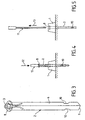
- a terminal according to the invention comprises a terminal head 1, a tubular anchoring member 2 and a locking means 3, for example in the form of a pin or a pin.
- the terminal head 1, the anchoring member 2 and the locking means 3 are independent of each other and can be transported separately.
- the terminal head 1 is preferably made of light material (molded plastic, lightweight resin concrete, aluminum, synthetic resin associated with light loads of sawdust, hollow glass beads, expanded polystyrene beads, ...) .
- the anchoring member 2 may also be made of lightweight material or thin.
- the terminal head 1 has a bore comprising an upper portion of large diameter and a lower portion of reduced diameter, so as to constitute at the bottom of the upper portion 4 of large diameter a shoulder 5 constituting a stop for the member 2 of anchorage.
- the anchoring member 2 has an elongated tubular portion 6 intended to penetrate into the ground through the reduced diameter bore portion 7 of the terminal head, and comprises a head collar 8 abutting on the shoulder 5.
- the anchoring member 2 is open at its lower end 9, constituted for example by a cut-off end of a tubular section assembled to the flange 8.
- the anchoring member 2 has at least one opening 10 and preferably two diametrically opposed openings 10 for the passage of the ends of the locking pin or pin 3 .
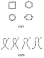
- the inside of the tube 6 has a guiding conformation: for this purpose, it is possible to use as elongate part 6 a square tube provided with two openings made diagonally through the wall of the square tube. During the descent of the pin or the elastic pin 3, the ends bear diagonally to the inside of the square tube 6 and are automatically guided to the openings 10 through which they must pass to ensure the locking of the terminal.
- the member 3 may be formed in the form of an elastic pin represented by reference to Figures 1 to 3 , or may adopt any other conformation without departing from the scope of the present invention, the essential being that the ends of the locking means 3 are shaped to pass through the openings 10 at the end of guiding.
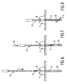
- a terminal laying method comprises the following successive steps:
- the terminal head 1 is placed at the required location on the ground to carry out the demarcation, the anchoring member 2 is engaged through the bore of the terminal head 1 and the anchoring member 2 is depressed. in the ground by means of a special driving tool 11 by striking it with a hammer not shown in the direction of the arrow 12.
- the tool 11 has a wide head adapted to abut on the collar 8 and a rod adapted to penetrate inside the anchoring member 2, preferably protruding from the latter through the opening 9.
- the use of the tool 11 stiffens the anchoring member 2 during depressing and allows the use of anchoring members 2 of light-walled thin material.
- Depressing the anchoring member 2 with the aid of the tool 11 is carried out until the flange 8 comes into contact with the terminal head 1.
- the tool 11 is removed as indicated by pulling upwards in the direction of the arrow 13 of the figure 5 .
- a pin or locking pin 3 is introduced inside the anchoring member 2 in an orientation corresponding to a guide of the end of the pin 3 by the generatrices on which the openings 10 are located.
- the locking is terminated by deforming the pin 3 to remove the ends of the pin 3 through the openings 10 and thus ensuring anchoring in the ground.
- the terminal head 1 is locked by the cooperation of the flange 8 of the anchoring member 2 with the shoulder 5 of the terminal head 1, with an anchor force greater than 4000 Newton.
- pin 3 or locking pin variants may have a cross-loop conformation 3a, a loop conformation 3b with S-bends to provide a better outlet through the openings 10 or a pin-like conformation 3c with curvatures in the form of S obtaining a better outlet through the openings 10, or a hairpin or pin 3 conformation with rounded ends or folded edges also facilitating the passage through the openings 10.
Landscapes
- Engineering & Computer Science (AREA)
- Structural Engineering (AREA)
- Civil Engineering (AREA)
- Architecture (AREA)
- General Engineering & Computer Science (AREA)
- Remote Sensing (AREA)
- Life Sciences & Earth Sciences (AREA)
- General Life Sciences & Earth Sciences (AREA)
- Mining & Mineral Resources (AREA)
- Paleontology (AREA)
- Physics & Mathematics (AREA)
- Radar, Positioning & Navigation (AREA)
- General Physics & Mathematics (AREA)
- Piles And Underground Anchors (AREA)
- Geophysics And Detection Of Objects (AREA)
- Catching Or Destruction (AREA)
- Mechanical Treatment Of Semiconductor (AREA)
- Investigation Of Foundation Soil And Reinforcement Of Foundation Soil By Compacting Or Drainage (AREA)
- Road Signs Or Road Markings (AREA)
- Polishing Bodies And Polishing Tools (AREA)
- Adornments (AREA)
Claims (11)
- Verfahren zum Verlegen eines Grenzsteins, das in Kombination die folgenden Schritte umfaßt:- Verlegen eines Grenzsteinkopfes (1) an der erforderlichen Stelle am Boden, um die Grenzmarkierung vorzunehmen,- Einführen eines Verankerungsorgans (2) durch eine Bohrung im Grenzsteinkopf (1),- Eintreiben des Verankerungsorgans (2) in den Boden mit Hilfe eines Eintreibwerkzeugs (11), das in das Innere des Verankerungsorgans (2) hineinläuft, um das Verankerungsorgan (6) bei dessen Eintreiben zu versteifen,- Herausziehen des Eintreibwerkzeugs (11) durch Zug nach oben (13),- Einführen eines Verriegelungsmittels (3) in das Innere des Verankerungsorgans (2),- Eintreiben des Verriegelungsmittels (3) in das Verankerungsorgan (2) mit Hilfe des Eintreibwerkzeugs (11),- Beenden der Verriegelung durch Verformen des Verriegelungsmittels (3), um mindestens ein Ende durch mindestens eine Auslaßöffnung (10) des Verankerungsorgans (2) austreten zu lassen und so eine Verankerung im Boden sicherzustellen.
- Grenzstein zur Durchführung des Verfahrens nach Anspruch 1, der in Kombination umfaßt:- einen Grenzsteinkopf (1), der mit einer Schulter (5) und einer Bohrung (4, 7) versehen ist,- ein Verankerungsorgan (2), das mit einem Haltekragen (8) und mit einem länglichen, hohlen Abschnitt (6) mit mindestens einer Auslaßöffnung (10) versehen ist,- ein Verriegelungsmittel (3),in Kombination dadurch gekennzeichnet, daß der Grenzsteinkopf (1), das Verankerungsorgan (2) und das Verriegelungsmittel (3) unabhängig voneinander sind, und daß das Verankerungsorgan am Ende des länglichen, hohlen Abschnittes (6) offen (9) ist und eine Innenformgebung zur Führung des Verriegelungsmittels (3) aufweist, wenn das Verriegelungsmittel (3) in das Innere der Innenformgebung hineingeschoben wird.
- Grenzstein nach Anspruch 2, dadurch gekennzeichnet, daß das Verankerungsorgan (2) aus einem leichten Material, z. B. Aluminium oder Kunststoff, gefertigt ist.
- Grenzstein nach Anspruch 2 oder Anspruch 3, dadurch gekennzeichnet, daß das Verankerungsorgan (2) einen rohrförmigen Abschnitt (6) mit einem regelmäßig-polygonalem Querschnitt aufweist, dessen einander diagonal gegenüberliegende Erzeugende eine Innenformgebung zur Führung des Verriegelungsmittels (3) ausbilden.
- Grenzstein nach Anspruch 2 oder Anspruch 3, dadurch gekennzeichnet, daß das Verankerungsorgan (2) einen rohrförmigen Abschnitt (6) mit Nuten oder Innenprofilen zur Führung des Verriegelungsmittels (3) aufweist.
- Grenzstein nach Anspruch 2 oder Anspruch 3, dadurch gekennzeichnet, daß das Verriegelungsmittel (3) als Nadel oder Dorn ausgebildet ist.
- Grenzstein nach Anspruch 2 oder Anspruch 3, dadurch gekennzeichnet, daß das Verriegelungsmittel als überkreuzte Schlaufe ausgebildet ist.
- Grenzstein nach Anspruch 6 oder Anspruch 7, dadurch gekennzeichnet, daß das Verriegelungsmittel (3) S-förmige Krümmungen aufweist, um seine Führung im Verlauf seiner Abwärtsbewegung zu verbessern und das Herausführen seiner Enden durch die Öffnungen (10) des länglichen, hohlen Abschnittes (6) zu erleichtern.
- Grenzstein nach Anspruch 6 oder Anspruch 7, dadurch gekennzeichnet, daß das Verriegelungsmittel (3) kugelförmige oder mit gefalzten Rändern versehene Enden aufweist, um deren Einführung in die Öffnungen (10) des länglichen, hohlen Abschnittes (6) zu erleichtern.
- Eintreibwerkzeug zur Durchführung des Verfahrens nach Anspruch 1 zum Verlegen eines Grenzsteins unter Verwendung eines Grenzsteins nach Anspruch 2 oder Anspruch 3, mit einem Kopf und einem Schaft, der länger als der längliche, hohle Abschnitt (6) des Verankerungsorgans (2) ist, um das Verankerungsorgan (6) bei dessen Eintreiben zu versteifen.
- Werkzeug nach Anspruch 10, dadurch gekennzeichnet, daß das Werkzeug ein spitzes oder sich verjüngendes Schaftende aufweist.
Applications Claiming Priority (2)
| Application Number | Priority Date | Filing Date | Title |
|---|---|---|---|
| FR0203057A FR2837278B1 (fr) | 2002-03-12 | 2002-03-12 | Borne topographique |
| FR0203057 | 2002-03-12 |
Publications (2)
| Publication Number | Publication Date |
|---|---|
| EP1345007A1 EP1345007A1 (de) | 2003-09-17 |
| EP1345007B1 true EP1345007B1 (de) | 2008-12-24 |
Family
ID=27763720
Family Applications (1)
| Application Number | Title | Priority Date | Filing Date |
|---|---|---|---|
| EP03290462A Expired - Lifetime EP1345007B1 (de) | 2002-03-12 | 2003-02-27 | Topographischer Abmarkungsstein |
Country Status (5)
| Country | Link |
|---|---|
| EP (1) | EP1345007B1 (de) |
| AT (1) | ATE418717T1 (de) |
| DE (1) | DE60325435D1 (de) |
| ES (1) | ES2320208T3 (de) |
| FR (1) | FR2837278B1 (de) |
Families Citing this family (3)
| Publication number | Priority date | Publication date | Assignee | Title |
|---|---|---|---|---|
| FR2907894B1 (fr) | 2006-10-25 | 2008-12-19 | Jean Edouard Gissinger | "borne topographique" |
| CN101650182B (zh) * | 2008-08-11 | 2013-08-07 | 上海市机械施工有限公司 | 桩内柱体直接测量方法 |
| WO2010049545A1 (es) * | 2008-10-28 | 2010-05-06 | Montur Estan, S.L. | Conjunto de hincado para perfiles de aluminio, y procedimiento de hincado |
Family Cites Families (2)
| Publication number | Priority date | Publication date | Assignee | Title |
|---|---|---|---|---|
| FR2244159B1 (de) * | 1973-09-17 | 1976-05-14 | Thevenin Jean Marie | |
| FR2692609B1 (fr) * | 1992-06-17 | 1995-10-13 | Batiborne Expl Ets Pernet Coud | Borne et procede de pose de celle-ci. |
-
2002
- 2002-03-12 FR FR0203057A patent/FR2837278B1/fr not_active Expired - Fee Related
-
2003
- 2003-02-27 EP EP03290462A patent/EP1345007B1/de not_active Expired - Lifetime
- 2003-02-27 ES ES03290462T patent/ES2320208T3/es not_active Expired - Lifetime
- 2003-02-27 AT AT03290462T patent/ATE418717T1/de not_active IP Right Cessation
- 2003-02-27 DE DE60325435T patent/DE60325435D1/de not_active Expired - Lifetime
Also Published As
| Publication number | Publication date |
|---|---|
| EP1345007A1 (de) | 2003-09-17 |
| ATE418717T1 (de) | 2009-01-15 |
| ES2320208T3 (es) | 2009-05-20 |
| DE60325435D1 (de) | 2009-02-05 |
| FR2837278B1 (fr) | 2004-06-04 |
| FR2837278A1 (fr) | 2003-09-19 |
Similar Documents
| Publication | Publication Date | Title |
|---|---|---|
| EP1664463B1 (de) | System zur Verankerung eines Objekts im Bodem mittels eines Pfahls | |
| FR3002956A1 (fr) | Paroi moulee precontrainte et procede de realisation d'une telle paroi | |
| EP0110925B1 (de) | Gerät zum einrammen und einbringen von befestigungszapfen für pfähle | |
| EP1345007A1 (de) | Topographischer Abmarkungsstein | |
| WO1980002173A1 (fr) | Dispositif de fixation a gaines glissieres en particulier pour poteaux | |
| WO1996012068A1 (fr) | Dispositif d'ancrage de fondation de structure dans le sol | |
| FR2692609A1 (fr) | Borne et procédé de pose de celle-ci. | |
| FR2926567A1 (fr) | Tige d'ancrage pour piquet d'ancrage au sol | |
| FR2979926A1 (fr) | Procede et piquet d'ancrage dans le sol | |
| FR2556793A1 (fr) | Cheville de fixation | |
| EP4124692B1 (de) | Versetzbare mauer mit betonskelett | |
| FR2718482A3 (fr) | Dispositif pour la fixation d'un appareil dans le sol. | |
| FR2524030A1 (fr) | Tete d'ancrage pour tirant composite precomprime a raccourcissement progressif | |
| FR2605346A1 (fr) | Piquet d'ancrage pour bornes et autres applications. | |
| BE1026357B1 (fr) | Bordure | |
| EP4520896B1 (de) | Führungsvorrichtung zur montage eines turmfasses und montageverfahren dafür | |
| KR101110039B1 (ko) | 앵커 헤드 | |
| FR2719328A1 (fr) | Borne et procédé de pose de celle-ci. | |
| EP1867882B1 (de) | Verankerungsvorrichtung mit Flügeldübeln | |
| FR2575781A1 (fr) | Dispositif de lame profilee enfouissable et basculante pour ancrage dans un terrain meuble ou similaire | |
| EP4589841A1 (de) | Trägerstruktur für mindestens eine solarzelle | |
| CA2191257C (fr) | Poteaux caoutchouc pour garde-fou routier | |
| WO2025238575A1 (fr) | Dispositif de poteau en matériau moulable | |
| FR2517715A1 (fr) | Borne a ancrage metallique de securite | |
| FR2804700A1 (fr) | Module pour bande podotactile et bande podotactile correspondante |
Legal Events
| Date | Code | Title | Description |
|---|---|---|---|
| PUAI | Public reference made under article 153(3) epc to a published international application that has entered the european phase |
Free format text: ORIGINAL CODE: 0009012 |
|
| AK | Designated contracting states |
Kind code of ref document: A1 Designated state(s): AT BE BG CH CY CZ DE DK EE ES FI FR GB GR HU IE IT LI LU MC NL PT SE SI SK TR |
|
| AX | Request for extension of the european patent |
Extension state: AL LT LV MK RO |
|
| 17P | Request for examination filed |
Effective date: 20040316 |
|
| AKX | Designation fees paid |
Designated state(s): AT BE BG CH CY CZ DE DK EE ES FI FR GB GR HU IE IT LI LU MC NL PT SE SI SK TR |
|
| AXX | Extension fees paid |
Extension state: LT Payment date: 20030319 Extension state: AL Payment date: 20030319 Extension state: LV Payment date: 20030319 Extension state: MK Payment date: 20030319 Extension state: RO Payment date: 20030319 |
|
| 17Q | First examination report despatched |
Effective date: 20040527 |
|
| 17Q | First examination report despatched |
Effective date: 20040527 |
|
| GRAP | Despatch of communication of intention to grant a patent |
Free format text: ORIGINAL CODE: EPIDOSNIGR1 |
|
| GRAS | Grant fee paid |
Free format text: ORIGINAL CODE: EPIDOSNIGR3 |
|
| GRAS | Grant fee paid |
Free format text: ORIGINAL CODE: EPIDOSNIGR3 |
|
| GRAA | (expected) grant |
Free format text: ORIGINAL CODE: 0009210 |
|
| AK | Designated contracting states |
Kind code of ref document: B1 Designated state(s): AT BE BG CH CY CZ DE DK EE ES FI FR GB GR HU IE IT LI LU MC NL PT SE SI SK TR |
|
| AX | Request for extension of the european patent |
Extension state: AL LT LV MK RO |
|
| REG | Reference to a national code |
Ref country code: GB Ref legal event code: FG4D Free format text: NOT ENGLISH |
|
| REG | Reference to a national code |
Ref country code: CH Ref legal event code: EP |
|
| REG | Reference to a national code |
Ref country code: IE Ref legal event code: FG4D Free format text: LANGUAGE OF EP DOCUMENT: FRENCH |
|
| REF | Corresponds to: |
Ref document number: 60325435 Country of ref document: DE Date of ref document: 20090205 Kind code of ref document: P |
|
| REG | Reference to a national code |
Ref country code: ES Ref legal event code: FG2A Ref document number: 2320208 Country of ref document: ES Kind code of ref document: T3 |
|
| LTIE | Lt: invalidation of european patent or patent extension |
Effective date: 20081224 |
|
| PG25 | Lapsed in a contracting state [announced via postgrant information from national office to epo] |
Ref country code: NL Free format text: LAPSE BECAUSE OF FAILURE TO SUBMIT A TRANSLATION OF THE DESCRIPTION OR TO PAY THE FEE WITHIN THE PRESCRIBED TIME-LIMIT Effective date: 20081224 Ref country code: SI Free format text: LAPSE BECAUSE OF FAILURE TO SUBMIT A TRANSLATION OF THE DESCRIPTION OR TO PAY THE FEE WITHIN THE PRESCRIBED TIME-LIMIT Effective date: 20081224 Ref country code: FI Free format text: LAPSE BECAUSE OF FAILURE TO SUBMIT A TRANSLATION OF THE DESCRIPTION OR TO PAY THE FEE WITHIN THE PRESCRIBED TIME-LIMIT Effective date: 20081224 |
|
| NLV1 | Nl: lapsed or annulled due to failure to fulfill the requirements of art. 29p and 29m of the patents act | ||
| REG | Reference to a national code |
Ref country code: IE Ref legal event code: FD4D |
|
| PG25 | Lapsed in a contracting state [announced via postgrant information from national office to epo] |
Ref country code: EE Free format text: LAPSE BECAUSE OF FAILURE TO SUBMIT A TRANSLATION OF THE DESCRIPTION OR TO PAY THE FEE WITHIN THE PRESCRIBED TIME-LIMIT Effective date: 20081224 Ref country code: BG Free format text: LAPSE BECAUSE OF FAILURE TO SUBMIT A TRANSLATION OF THE DESCRIPTION OR TO PAY THE FEE WITHIN THE PRESCRIBED TIME-LIMIT Effective date: 20090324 Ref country code: IE Free format text: LAPSE BECAUSE OF FAILURE TO SUBMIT A TRANSLATION OF THE DESCRIPTION OR TO PAY THE FEE WITHIN THE PRESCRIBED TIME-LIMIT Effective date: 20081224 |
|
| PG25 | Lapsed in a contracting state [announced via postgrant information from national office to epo] |
Ref country code: SE Free format text: LAPSE BECAUSE OF FAILURE TO SUBMIT A TRANSLATION OF THE DESCRIPTION OR TO PAY THE FEE WITHIN THE PRESCRIBED TIME-LIMIT Effective date: 20090324 Ref country code: PT Free format text: LAPSE BECAUSE OF FAILURE TO SUBMIT A TRANSLATION OF THE DESCRIPTION OR TO PAY THE FEE WITHIN THE PRESCRIBED TIME-LIMIT Effective date: 20090525 Ref country code: CZ Free format text: LAPSE BECAUSE OF FAILURE TO SUBMIT A TRANSLATION OF THE DESCRIPTION OR TO PAY THE FEE WITHIN THE PRESCRIBED TIME-LIMIT Effective date: 20081224 Ref country code: AT Free format text: LAPSE BECAUSE OF FAILURE TO SUBMIT A TRANSLATION OF THE DESCRIPTION OR TO PAY THE FEE WITHIN THE PRESCRIBED TIME-LIMIT Effective date: 20081224 |
|
| PG25 | Lapsed in a contracting state [announced via postgrant information from national office to epo] |
Ref country code: SK Free format text: LAPSE BECAUSE OF FAILURE TO SUBMIT A TRANSLATION OF THE DESCRIPTION OR TO PAY THE FEE WITHIN THE PRESCRIBED TIME-LIMIT Effective date: 20081224 Ref country code: MC Free format text: LAPSE BECAUSE OF NON-PAYMENT OF DUE FEES Effective date: 20090228 |
|
| REG | Reference to a national code |
Ref country code: CH Ref legal event code: PL |
|
| PG25 | Lapsed in a contracting state [announced via postgrant information from national office to epo] |
Ref country code: LI Free format text: LAPSE BECAUSE OF NON-PAYMENT OF DUE FEES Effective date: 20090228 Ref country code: DK Free format text: LAPSE BECAUSE OF FAILURE TO SUBMIT A TRANSLATION OF THE DESCRIPTION OR TO PAY THE FEE WITHIN THE PRESCRIBED TIME-LIMIT Effective date: 20081224 Ref country code: CH Free format text: LAPSE BECAUSE OF NON-PAYMENT OF DUE FEES Effective date: 20090228 |
|
| PLBE | No opposition filed within time limit |
Free format text: ORIGINAL CODE: 0009261 |
|
| STAA | Information on the status of an ep patent application or granted ep patent |
Free format text: STATUS: NO OPPOSITION FILED WITHIN TIME LIMIT |
|
| 26N | No opposition filed |
Effective date: 20090925 |
|
| PG25 | Lapsed in a contracting state [announced via postgrant information from national office to epo] |
Ref country code: GR Free format text: LAPSE BECAUSE OF FAILURE TO SUBMIT A TRANSLATION OF THE DESCRIPTION OR TO PAY THE FEE WITHIN THE PRESCRIBED TIME-LIMIT Effective date: 20090325 |
|
| PG25 | Lapsed in a contracting state [announced via postgrant information from national office to epo] |
Ref country code: LU Free format text: LAPSE BECAUSE OF NON-PAYMENT OF DUE FEES Effective date: 20090227 |
|
| PG25 | Lapsed in a contracting state [announced via postgrant information from national office to epo] |
Ref country code: HU Free format text: LAPSE BECAUSE OF FAILURE TO SUBMIT A TRANSLATION OF THE DESCRIPTION OR TO PAY THE FEE WITHIN THE PRESCRIBED TIME-LIMIT Effective date: 20090625 |
|
| PG25 | Lapsed in a contracting state [announced via postgrant information from national office to epo] |
Ref country code: TR Free format text: LAPSE BECAUSE OF FAILURE TO SUBMIT A TRANSLATION OF THE DESCRIPTION OR TO PAY THE FEE WITHIN THE PRESCRIBED TIME-LIMIT Effective date: 20081224 |
|
| PG25 | Lapsed in a contracting state [announced via postgrant information from national office to epo] |
Ref country code: CY Free format text: LAPSE BECAUSE OF FAILURE TO SUBMIT A TRANSLATION OF THE DESCRIPTION OR TO PAY THE FEE WITHIN THE PRESCRIBED TIME-LIMIT Effective date: 20081224 |
|
| PGFP | Annual fee paid to national office [announced via postgrant information from national office to epo] |
Ref country code: IT Payment date: 20150224 Year of fee payment: 13 Ref country code: DE Payment date: 20150219 Year of fee payment: 13 |
|
| PGFP | Annual fee paid to national office [announced via postgrant information from national office to epo] |
Ref country code: GB Payment date: 20150218 Year of fee payment: 13 |
|
| REG | Reference to a national code |
Ref country code: FR Ref legal event code: PLFP Year of fee payment: 14 |
|
| REG | Reference to a national code |
Ref country code: DE Ref legal event code: R119 Ref document number: 60325435 Country of ref document: DE |
|
| GBPC | Gb: european patent ceased through non-payment of renewal fee |
Effective date: 20160227 |
|
| PG25 | Lapsed in a contracting state [announced via postgrant information from national office to epo] |
Ref country code: IT Free format text: LAPSE BECAUSE OF NON-PAYMENT OF DUE FEES Effective date: 20160227 |
|
| PG25 | Lapsed in a contracting state [announced via postgrant information from national office to epo] |
Ref country code: GB Free format text: LAPSE BECAUSE OF NON-PAYMENT OF DUE FEES Effective date: 20160227 Ref country code: DE Free format text: LAPSE BECAUSE OF NON-PAYMENT OF DUE FEES Effective date: 20160901 |
|
| REG | Reference to a national code |
Ref country code: FR Ref legal event code: PLFP Year of fee payment: 15 |
|
| PGFP | Annual fee paid to national office [announced via postgrant information from national office to epo] |
Ref country code: BE Payment date: 20170216 Year of fee payment: 15 |
|
| PGFP | Annual fee paid to national office [announced via postgrant information from national office to epo] |
Ref country code: ES Payment date: 20170213 Year of fee payment: 15 |
|
| REG | Reference to a national code |
Ref country code: FR Ref legal event code: PLFP Year of fee payment: 16 |
|
| REG | Reference to a national code |
Ref country code: BE Ref legal event code: MM Effective date: 20180228 |
|
| PG25 | Lapsed in a contracting state [announced via postgrant information from national office to epo] |
Ref country code: BE Free format text: LAPSE BECAUSE OF NON-PAYMENT OF DUE FEES Effective date: 20180228 |
|
| REG | Reference to a national code |
Ref country code: ES Ref legal event code: FD2A Effective date: 20190801 |
|
| PG25 | Lapsed in a contracting state [announced via postgrant information from national office to epo] |
Ref country code: ES Free format text: LAPSE BECAUSE OF NON-PAYMENT OF DUE FEES Effective date: 20180228 |
|
| PGFP | Annual fee paid to national office [announced via postgrant information from national office to epo] |
Ref country code: FR Payment date: 20200219 Year of fee payment: 18 |
|
| PG25 | Lapsed in a contracting state [announced via postgrant information from national office to epo] |
Ref country code: FR Free format text: LAPSE BECAUSE OF NON-PAYMENT OF DUE FEES Effective date: 20210228 |