EP1344935A2 - Verfahren und Vorrichtung zur Lastausgleichung zwischen mehreren Verdichtern - Google Patents
Verfahren und Vorrichtung zur Lastausgleichung zwischen mehreren Verdichtern Download PDFInfo
- Publication number
- EP1344935A2 EP1344935A2 EP03005703A EP03005703A EP1344935A2 EP 1344935 A2 EP1344935 A2 EP 1344935A2 EP 03005703 A EP03005703 A EP 03005703A EP 03005703 A EP03005703 A EP 03005703A EP 1344935 A2 EP1344935 A2 EP 1344935A2
- Authority
- EP
- European Patent Office
- Prior art keywords
- compressors
- compressor
- fluid
- valve
- valve positions
- Prior art date
- Legal status (The legal status is an assumption and is not a legal conclusion. Google has not performed a legal analysis and makes no representation as to the accuracy of the status listed.)
- Withdrawn
Links
- 238000000034 method Methods 0.000 title claims abstract description 30
- 239000012530 fluid Substances 0.000 claims abstract description 62
- 238000005265 energy consumption Methods 0.000 claims abstract description 37
- 230000003247 decreasing effect Effects 0.000 claims description 9
- 238000004590 computer program Methods 0.000 claims description 4
- 230000015654 memory Effects 0.000 claims description 3
- 238000009795 derivation Methods 0.000 claims 1
- 230000010354 integration Effects 0.000 claims 1
- 238000004519 manufacturing process Methods 0.000 description 20
- 238000004364 calculation method Methods 0.000 description 7
- 238000004458 analytical method Methods 0.000 description 6
- 239000011159 matrix material Substances 0.000 description 2
- 238000004891 communication Methods 0.000 description 1
- 230000007423 decrease Effects 0.000 description 1
- 238000010586 diagram Methods 0.000 description 1
- 230000006870 function Effects 0.000 description 1
- 238000005259 measurement Methods 0.000 description 1
- 238000003825 pressing Methods 0.000 description 1
- XLYOFNOQVPJJNP-UHFFFAOYSA-N water Substances O XLYOFNOQVPJJNP-UHFFFAOYSA-N 0.000 description 1
Images


Classifications
-
- F—MECHANICAL ENGINEERING; LIGHTING; HEATING; WEAPONS; BLASTING
- F04—POSITIVE - DISPLACEMENT MACHINES FOR LIQUIDS; PUMPS FOR LIQUIDS OR ELASTIC FLUIDS
- F04C—ROTARY-PISTON, OR OSCILLATING-PISTON, POSITIVE-DISPLACEMENT MACHINES FOR LIQUIDS; ROTARY-PISTON, OR OSCILLATING-PISTON, POSITIVE-DISPLACEMENT PUMPS
- F04C28/00—Control of, monitoring of, or safety arrangements for, pumps or pumping installations specially adapted for elastic fluids
- F04C28/02—Control of, monitoring of, or safety arrangements for, pumps or pumping installations specially adapted for elastic fluids specially adapted for several pumps connected in series or in parallel
-
- F—MECHANICAL ENGINEERING; LIGHTING; HEATING; WEAPONS; BLASTING
- F04—POSITIVE - DISPLACEMENT MACHINES FOR LIQUIDS; PUMPS FOR LIQUIDS OR ELASTIC FLUIDS
- F04B—POSITIVE-DISPLACEMENT MACHINES FOR LIQUIDS; PUMPS
- F04B41/00—Pumping installations or systems specially adapted for elastic fluids
- F04B41/06—Combinations of two or more pumps
-
- F—MECHANICAL ENGINEERING; LIGHTING; HEATING; WEAPONS; BLASTING
- F04—POSITIVE - DISPLACEMENT MACHINES FOR LIQUIDS; PUMPS FOR LIQUIDS OR ELASTIC FLUIDS
- F04C—ROTARY-PISTON, OR OSCILLATING-PISTON, POSITIVE-DISPLACEMENT MACHINES FOR LIQUIDS; ROTARY-PISTON, OR OSCILLATING-PISTON, POSITIVE-DISPLACEMENT PUMPS
- F04C23/00—Combinations of two or more pumps, each being of rotary-piston or oscillating-piston type, specially adapted for elastic fluids; Pumping installations specially adapted for elastic fluids; Multi-stage pumps specially adapted for elastic fluids
- F04C23/001—Combinations of two or more pumps, each being of rotary-piston or oscillating-piston type, specially adapted for elastic fluids; Pumping installations specially adapted for elastic fluids; Multi-stage pumps specially adapted for elastic fluids of similar working principle
-
- F—MECHANICAL ENGINEERING; LIGHTING; HEATING; WEAPONS; BLASTING
- F04—POSITIVE - DISPLACEMENT MACHINES FOR LIQUIDS; PUMPS FOR LIQUIDS OR ELASTIC FLUIDS
- F04C—ROTARY-PISTON, OR OSCILLATING-PISTON, POSITIVE-DISPLACEMENT MACHINES FOR LIQUIDS; ROTARY-PISTON, OR OSCILLATING-PISTON, POSITIVE-DISPLACEMENT PUMPS
- F04C28/00—Control of, monitoring of, or safety arrangements for, pumps or pumping installations specially adapted for elastic fluids
- F04C28/06—Control of, monitoring of, or safety arrangements for, pumps or pumping installations specially adapted for elastic fluids specially adapted for stopping, starting, idling or no-load operation
-
- F—MECHANICAL ENGINEERING; LIGHTING; HEATING; WEAPONS; BLASTING
- F04—POSITIVE - DISPLACEMENT MACHINES FOR LIQUIDS; PUMPS FOR LIQUIDS OR ELASTIC FLUIDS
- F04D—NON-POSITIVE-DISPLACEMENT PUMPS
- F04D25/00—Pumping installations or systems
- F04D25/16—Combinations of two or more pumps ; Producing two or more separate gas flows
-
- F—MECHANICAL ENGINEERING; LIGHTING; HEATING; WEAPONS; BLASTING
- F04—POSITIVE - DISPLACEMENT MACHINES FOR LIQUIDS; PUMPS FOR LIQUIDS OR ELASTIC FLUIDS
- F04D—NON-POSITIVE-DISPLACEMENT PUMPS
- F04D27/00—Control, e.g. regulation, of pumps, pumping installations or pumping systems specially adapted for elastic fluids
- F04D27/02—Surge control
- F04D27/0269—Surge control by changing flow path between different stages or between a plurality of compressors; load distribution between compressors
Definitions
- the present invention relates to a system and a method for controlling a number of compressors arranged for jointly producing and delivering a pressurized fluid, such as air, freon, oil, or water, to a plant.
- Each of the compressors comprises a valve, wherein the position of the valve determines the size of the flow of the fluid.
- the compressors can have at least three different states: a shut-off state in which the compressor has zero voltage and the valve is in a closed position, an unloaded state in which the compressor is under a voltage and the valve is in a closed position, and a loaded state in which the compressor is under a voltage and the valve is in an at least partly opened position.
- the system according to the invention is advantageously used for controlling compressors for production of pressurized air, but may also be used for controlling other types of compressors, for example for refrigerate production.
- compressor centrals are often used for producing pressurized air for different purposes, for example pneumatic tools.
- a compressor central usually comprises a number of compressors, which are connected to a common container of pressurized air, which is connected to pneumatic devices in the plant, for example a pneumatic drill, a pressing tool, or a conveyor.
- the compressors of the compressor central may have different capacities for delivering air, i.e. the amount of delivered air per unit of time may vary between the compressors. Some of the compressors can only deliver a determined amount of air per unit of time, while others can deliver a varying amount of air per unit of time.
- the pressure in the container is usually somewhere in the range 1-12 bar.
- the pressure in the container is measured by a gauge and in dependence of whether the pressure in the container exceeds or is lower than a predetermined limit, some of the compressors are started or shut off. Which of the processors is to be started or shut off is decided based on predetermined sequences.
- a sequence specifies on one hand which compressor is the base compressor, i.e. the compressor which shall be connected first and deliver the base pressure and on the other hand the order in which the other compressors are to be connected or disconnected, if the pressure is not enough or is too high.
- One or a plurality of sequences may control the compressor central. Different sequences can be used in dependence the time of the day, the day of the week, or the shift working.
- sequences are determined in advance based on previous experiences of the varying need of pressurized air during the day and night. If the pressure in the container exceeds the limit, the next compressor in the sequence is connected, and if the pressure is lower than the limit, the sequence decides which of the compressors to be disconnected.
- a disadvantage with those compressor centrals is that they are very energy demanding and also have a low efficiency.
- the efficiency for incoming current to active mechanical work is about 4%.
- One of the reasons for the low efficiency is that the compressors during a great part of the time are in the unloaded state.
- a compressor in an unloaded state consumes energy without performing any work.
- the energy consumption in an unloaded state can be as much as 40-50% of the energy consumption in a loaded state.
- the object of the present invention is to provide a method for controlling a plurality of compressors that jointly produce a fluid, which method makes it possible to lower the energy consumption and obtains a high efficiency in relation to the above discussed prior art.
- the method comprises storing information for each of the compressors regarding the power that the compressor consumes in the loaded and the unloaded states and which flow or flows the compressor can deliver.
- Information regarding the pressure of the fluid and the current valve positions for the compressors are received.
- the current need of fluid is estimated, based on the current valve positions of the compressors, the flow that the compressors can deliver and the pressure in the fluid.
- the valve positions of the compressors are adjusted with regard to the current need of fluid and the energy consumptions of the compressors in a number of possible sets of valve positions that meet the current need of fluid. In a preferred embodiment, the set of valve positions that achieves the lowest energy consumption is produced.
- valve positions of the compressors is for example adjusted with regard to a condition allowing the energy consumption of the compressors is to be at the most 10% larger than the energy consumption of the set of valve positions that achieves the lowest energy consumption.
- a number of possible sets of different combinations of valve positions are produced. For each of said set of valve position, the flow that the set produces is calculated and from said sets of possible combinations of valve positions, one set of valve positions is chosen that meets the current need of flow with regard to the energy consumption of the compressors, based on the power consumed by the compressors in the loaded and unloaded states. In a preferred embodiment, it is decided for said chosen sets of valve positions which of the sets achieves the lowest energy consumption. By producing all possible combinations of valve positions for the compressors, calculating the flow that those combinations achieve, and then comparing the flows with the current need of fluid, it is possible to determine which combinations of valve positions meet the current need of fluid. When the combinations are decided, one of them is chosen in dependence of its energy consumption.
- the current need of fluid is estimated by calculation of the current flow, based on the current valve positions of the compressors and the flow that they can deliver, and whether the flow has to be changed or not is determined in dependence of the pressure in the fluid. Calculating the current flow, and using the pressure to decide whether the pressure has to be increased or decreased, obtain an estimation of the current need by means of a condition telling whether the flow shall be larger than or less than a certain value. By later trying whether a set of valve positions fulfils the condition or not, it can easily be established whether the set of valve positions fulfils the current need of fluid or not.
- the pressure in the fluid is compared with an upper and a lower limit for the pressure, and whether the flow has to be increased or decreased is determined in dependence of said comparison.
- the upper limit for the pressure is more than 5% higher than the lower limit.
- the derivative for the pressure in the fluid is calculated, and whether the flow has to be increased or decreased is determined in dependence of the calculated derivative.
- the integral for the pressure in the fluid is calculated, and whether the fluid has to be changed is determined in dependence of the calculated integral. If the limits for the pressure are strictly followed during the judgment of the current need, the control will become jerky and sometimes leads to unnecessary starts and stops of the compressors. By also considering the integral of the pressure during the judgment of whether the flow has to be changed, not necessary starts and stops of the compressors are avoided in connection with occasional variations of the pressure in the container, for example at pressure peaks and minor breaks of the pressure limits. Accordingly, a more gentle control is obtained.
- the times that the compressors are in the unloaded state are measured, and when the time for any compressor exceeds a given limit, a control signal is generated for transferring the compressor to the shut-off state and information is stored about the fact that the compressor is shut off.
- a compressor being in an unloaded state may quickly change to a loaded state, but an unloaded compressor needs a period of time before it can start. By avoiding to shut off the compressor immediately when it is no longer needed and instead wait for a while and let the compressors stay in the unloaded position, there is still a possibility, if the need for fluid will increase again soon, to quickly start the processor again.
- valve positions of the processors are adjusted with regard to the stored information about which of the compressors is shut off.
- the valve positions of the compressors are adjusted with regard to how many times each of the compressors is allowed to start during a given time interval.
- information is stored about the number of times per unit of time the compressor has changed from a shut-off state to a loaded state and the number of times per unit of time is compared with a maximum allowed number of times per unit of time, and in dependence of the comparison it is decided whether the compressor is available or not and during adjustment of the valve positions it is considered which compressors are available.
- Another object of the present invention is to provide a computer program directly loadable into the internal memory of a computer, comprising instructions for causing a processor to execute the steps in the method according to the invention.
- Another object of the present invention is to provide a computer readable medium comprising a computer program comprising instructions for making a processor execute the steps in the method according to the invention.
- Another object of the present invention is to provide a system for controlling a plurality of compressors that jointly produce a fluid, which makes it possible to lower the energy consumption and to achieve a high efficiency.
- This object is achieved by the initially mentioned system and is characterized in that it comprises means for feeding and storing information about the power consumed by the compressors in the loaded and the unloaded states and which flow or flows the compressors can deliver, means for estimating the current need of fluid, based on current valve positions for the compressors, the flow which the compressors can deliver, and the pressure, as well as means for producing a set of valve positions with regard to the current need of fluid and energy consumption of the compressor, based on a number of possible sets of valve positions that meet the current need of fluid.
- Figure 1 shows a compressor central comprising three compressors 1, 2, 3 arranged for delivering pressurized air to a container 5.
- Each of the compressors 1-3 comprises a valve 7, 8, 9, the position of the valve deciding the size of the flow of air from the compressors.
- the compressors can have three different states: a shut-off state in which the compressor has a zero voltage and the valve is in a closed position, an unloaded state in which the compressor is under a voltage and the valve is in a closed position, and a loaded state in which the compressor is under a voltage and the valve is completely open.
- the compressor produces pressurized air only in the loaded state.
- the compressors are of the on/off type machines, i.e. either do they produce a maximum flow or they produce now flow at all. There are also compressors having a variable flow production.
- the invention is also useful for those compressors and further in the text an embodiment example is described with a compressor central comprising a compressor having a variable flow production.
- All three compressors 1, 2, 3 deliver pressurized air to the container 5. From the container 5, the pressurized air is further delivered to a plant 10, where different consumers receive the air. The consumers are, for example, tools or conveyors driven by pressurized air.
- the pressure P 1 (t) in the container is measured by means of a pressure gauge 12 arranged in the container.
- the pressures P 2 (t), P 3 (t), P 4 (t) are also measured in three different locations in the plant, by means of three pressure gauges 13.
- the pressure gauges 13 are positioned at critical points, where it is important for the functioning that a certain pressure is maintained and the pressure is not allowed to be below given levels.
- Data from the compressors in the compressor central 1, 2, 3, the container 5, and the plant 10 are transferred to a system 15 for control of the compressors. Control signals and data are transferred between the system 15 and the compressors and a plant via a bus connection 16.
- the system 15 comprises a processor, memories, and I/O units for communication with other units. From the compressors 1, 2, 3 information about current positions of the valves 7, 8, 9 is transferred to the system 15. From the container 5 and the plant 10 information regarding the pressure in the container 5 and in the critical points 13 is transferred to the system 15. The system 15 is also connected to a computer 18, which enables an operator to communicate with the system 15 and to feed data to the system. Data fed via the computer 18 is information regarding the power that each of the compressors consumes in the loaded and unloaded state, and the maximum flow that each of the compressors can deliver. One task of the system 15 is to estimate the current need of fluid and with regard to the current need of fluid determine the valve positions that achieve the lowest total energy consumption for all the compressors. Another task for the system 15 is to send control signals to the compressors regarding to change the state.
- Fig. 2 shows, in the form of a flow scheme, how the system 15 produces the valve positions that achieve the lowest energy consumption.
- a first step box 20
- data regarding the power that each of the compressors consumes in the loaded state P P / n and the unloaded state P a / n , and the flow f n that the compressors deliver in the loaded state are read.
- the flow is specified in litres per minute.
- Those data regarding the compressors are stored and do not have to be read again until any information is changed.
- information regarding the pressure P 1 (t) in the container and the pressures P 2 (t)-P 4 (t) in the critical points in the plant are read, box 21, and current valve positions ⁇ n for each of the compressors are read, box 22.
- valve positions have either the value 0 or the value 1. If the valve position has the value 0, the valve is closed and if it has the value 1, the valve is entirely open. The reading of input data is carried out with an optional time interval.
- limits are set for the allowed pressure. In some of the critical points, it is enough with a lower limit that the pressure must exceed.
- both an upper limit P max and a lower limit P min are provided, which present an interval for the allowed variation of the pressure. It is important to allow as large a pressure difference as possible between the upper and the lower limit without jeopardizing the function of the connected components.
- the difference between the limits P max -P min should be at least 5%, but preferably as much as 10%. How large a pressure difference to be allowed depends on several factors, such as the demands on the plant, the type of industry, and the size of the container.
- the upper limit is preferably set to 7,5 bar and P min is preferably set to 6,5 bar.
- P min is preferably set to 6,5 bar.
- the pressure in the fluid is compared with the lower limit P min , box 24, and with the upper limit P max , box 25, and if the pressure is within the limits, there is no adjustment of the valve positions, provided that it is not the first time that the program is run through. Should it be the first time that the program is run through, a determination of optimal valve positions is made, box 27, in the same way as is described ahead in the text, and control signals are generated for adjustment of the valve positions in accordance with the optimised valve positions, box 28. If the pressure in any of the measure points is lower than the lower limit, it is possible that another compressor has to be started. Before any step is taken, it is decided whether it really is necessary to increase the flow production.
- the derivative of the pressure ⁇ P / ⁇ t, box 31 is calculated.
- the derivative ⁇ P / ⁇ t is calculated according to the following equation: P(t+1)-P(t) ⁇ t
- the control system should not react by a further increase of the flow, since the pressure already is close to the limit and the pressure is strongly increasing.
- the derivative is calculated, box 30, if the pressure is larger than the maximum limit. If the derivative has a large negative value, which means that the pressure is rapidly decreasing, and the pressure is less than 1,15 ⁇ P max , the system is not allowed to react with a further lowering of the flow. Since the pressure is already decreasing and it is also close to the maximum limit, no measure is taken in this case.
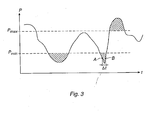
- Fig. 3 shows an example of how the pressure varies over time. At rapid changes in the pressure, the measurements of the derivative are uncertain. If the calculations of the derivative is based on the pressure in the points A and B, as shown in Fig. 3, the derivative will have the value 0, which is erroneous, since the derivative in the point B instead is strongly increasing.
- This example shows that a decision based only on an analysis of the derivative outside the upper P max and the lower P min limit for the pressure is not reliable.
- the integral for the pressure is also calculated when the pressure is outside the limits, boxes 32 and 33. The integral for the pressure is calculated as long as the pressure is below P min or above P max . As long as the pressure remains within the limits, the integral is not calculated.
- the central comprises three compressors of the type on/off-machines, which means that there are seven possible sets of combinations of valve positions.
- the total flow F i that those valve positions provide are calculated.
- the flow F i that each set provides is calculated by the equation 1. It is to be noted that several sets of valve positions may provide the same flow. The production of possible sets of valve positions and the flows obtained from those can be calculated once and for all.
- the calculated flows F i for the sets are compared with the calculated current flow F A from equation 1. If the analysis above has shown that the flow should increase, the sets of valve positions that achieve a flow F B next higher to the current flow F A is chosen. If the flow is about to be increased, box 37, the following boundary condition is valid: F i ⁇ F B > F A
- the formula 4d constitutes an optimisation problem, which gives a matrix that can be solved either by commercial or private constructed optimising solutions. Which of the boundary conditions 4a, 4b, or 4c is used depends on the current need of fluid.
- the solution of the optimisation problem is the set of valve positions that provides the lowest power output. If the number of compressors is large, this calculation is time consuming and it is suitable to use any known optimisation method for finding a solution to the optimisation problem.
- the mathematical optimisation problem is the same for the boxes 27, 36, and 37. What is changed in the model, in dependence of whether the flow is about to be increased or decreased, is which of the boundary conditions 4a, 4b, and 4c to be used.
- control signals to the compressors are generated regarding which states they shall have and which positions the valves shall have, boxes 28, 38, and 39.
- This method for finding and adjusting the optimal valve positions is repeated with an optional interval, so that the compressors always have optimal valve positions.
- all of the compressors are of an on/off type.
- the invention is also applicable to compressors having a variable, or partly variable, flow production.
- a compressor with a partly variable flow production has three distinct valve positions: a first position in which the valve is closed and no production of pressurized air will occur, a second state yielding a minimum production of pressurized air, and a third state in which the valve is completely open, and the compressor delivers the maximum of what it is able to deliver.
- the flow is variable between the second and the third position.
- the range between the second and the third position is divided into a plurality of discrete positions. The division of the discrete positions is optional and depends on the desired accuracy. During the calculation of the current flow production, a separate addition is also needed if the compressor central comprises compressors with a variable flow range.
- the compressor central in the above-described example is supplemented with a compressor having a partly variable flow range, wherein the flow can be either 0 or vary between 5 and 10 flow units.
- a division of the range between 5 and 10 flow units is made in steps of 1 flow unit.
- the flow from the fourth compressor is given by the equation:
- All compressors with a variable flow range are divided into M discrete flow positions. This division can be made machine specific by means of a variable index. Each discrete flow position corresponds to a certain electrical power output.
- F A The current flow production F A is calculated in the case with four compressors by the equation 6.
- F A is calculated by the following equation:
- the value for F B or F C is decided in dependence of whether the flow shall be increased or decreased.
- the boundary conditions in this embodiment example are given by 4a, 4b or 4c, wherein the total flow F i that the valve positions can give is calculated by the following equation:
- a compressor should not be changed directly from a loaded state to an unloaded state.
- the compressor should first be in the unloaded state for a certain period of time, before it is transferred to the closed state.
- the system 15 keeps track of the states of all the compressors and when a compressor changes from a loaded state to an unloaded state, a logging of the time in the unloaded state is started. For each of the compressors, the period of time that the compressor should stay in the unloaded state before the motor is turned off, is fed. This period of time may be optionally chosen and depends, for example, on the compressor size.
- the measured period of time in the unloaded state is compared with the fed period of time and when the measured period of time exceeds the period of time that the compressor should stay in the unloaded state, the system sends a control signal to the motor and turns it off. Simultaneously, information about the fact that the compressor has been turned off is stored.
- the system also keeps track of how many times per hour each of the compressors has been started.
- the number of allowed starts per hour depends on the efficiency of the compressor.
- the number of allowed starts decreases with a higher motor efficiency.
- a rule of thumb is that compressors with a motor efficiency of 90 kW are allowed to make ten starts per hour, while a compressor with a motor efficiency of 5 kW is allowed to make fifty starts per hour.
- the system keeps track of the number of starts the next hour. If the motor should be turned off without the compressor first being in the unloaded position, it will take about 30 seconds before the compressor is able to start again. That depends on the fact that the internal container of the compressor first has to be emptied before the motor is able to start again. Otherwise, the resistance will become too large.
- the time it takes for the internal container of the compressor to be emptied is about 30 seconds during unloading.
- the number of starts during a certain period of time is based on the temperature in the motor.
- the system must find out whether there is any compressors which are not allowed to be started. Depending on their size, the compressors could have been started three or ten times the last hour. Accordingly, when the combinations that fulfil the current need and during the calculation of the matrix 4 or 8, it is thus necessary to consider which compressors are available and which are not available.
- the time from the shut-off state to full air production and from the unloaded state to full air production is adjustable for each machine. If an optimisation solution tells that a certain compressor, which is in the shut-off state, is to be started, a time gap occurs before the compressor is able to deliver full air production. A question that arises is how the system should act, if the optimisation has given that a turned off compressor should be started, but at the same time there is an unloaded compressor that can be started much faster. If the network that delivers the pressurized air to the consumers and the pressure container have enough inertia, the pressure is prevented from decreasing too much during the time gap, and the use of any unloaded compressor is not necessary.
Applications Claiming Priority (2)
| Application Number | Priority Date | Filing Date | Title |
|---|---|---|---|
| SE0200752 | 2002-03-14 | ||
| SE0200752A SE521518C2 (sv) | 2002-03-14 | 2002-03-14 | Förfarande och system för att styra ett antal kompressorer |
Publications (2)
| Publication Number | Publication Date |
|---|---|
| EP1344935A2 true EP1344935A2 (de) | 2003-09-17 |
| EP1344935A3 EP1344935A3 (de) | 2003-12-10 |
Family
ID=20287245
Family Applications (1)
| Application Number | Title | Priority Date | Filing Date |
|---|---|---|---|
| EP03005703A Withdrawn EP1344935A3 (de) | 2002-03-14 | 2003-03-13 | Verfahren und Vorrichtung zur Lastausgleichung zwischen mehreren Verdichtern |
Country Status (2)
| Country | Link |
|---|---|
| EP (1) | EP1344935A3 (de) |
| SE (1) | SE521518C2 (de) |
Cited By (2)
| Publication number | Priority date | Publication date | Assignee | Title |
|---|---|---|---|---|
| EP2573400B1 (de) | 2008-12-23 | 2021-10-13 | Kaeser Kompressoren Se | Verfahren zum Steuern einer Kompressoranlage |
| EP4105490A1 (de) * | 2021-06-14 | 2022-12-21 | Air Products and Chemicals, Inc. | Verfahren und vorrichtung zum betreiben eines kompressionssystems |
Citations (4)
| Publication number | Priority date | Publication date | Assignee | Title |
|---|---|---|---|---|
| US4580947A (en) * | 1984-01-11 | 1986-04-08 | Hitachi, Ltd. | Method of controlling operation of a plurality of compressors |
| US5231846A (en) * | 1993-01-26 | 1993-08-03 | American Standard Inc. | Method of compressor staging for multi-compressor multi-circuited refrigeration systems |
| EP0593225A1 (de) * | 1992-10-13 | 1994-04-20 | Ingersoll-Rand Company | Methode und Vorrichtung zur Kontrolle der Lastverteilung eines Kompressorsystems |
| US6233954B1 (en) * | 1999-04-28 | 2001-05-22 | Ingersoll-Rand Company | Method for controlling the operation of a compression system having a plurality of compressors |
Family Cites Families (1)
| Publication number | Priority date | Publication date | Assignee | Title |
|---|---|---|---|---|
| JP2508695B2 (ja) * | 1987-03-27 | 1996-06-19 | 石川島播磨重工業株式会社 | 圧縮機の複数台並列運転方法及び装置 |
-
2002
- 2002-03-14 SE SE0200752A patent/SE521518C2/sv not_active IP Right Cessation
-
2003
- 2003-03-13 EP EP03005703A patent/EP1344935A3/de not_active Withdrawn
Patent Citations (4)
| Publication number | Priority date | Publication date | Assignee | Title |
|---|---|---|---|---|
| US4580947A (en) * | 1984-01-11 | 1986-04-08 | Hitachi, Ltd. | Method of controlling operation of a plurality of compressors |
| EP0593225A1 (de) * | 1992-10-13 | 1994-04-20 | Ingersoll-Rand Company | Methode und Vorrichtung zur Kontrolle der Lastverteilung eines Kompressorsystems |
| US5231846A (en) * | 1993-01-26 | 1993-08-03 | American Standard Inc. | Method of compressor staging for multi-compressor multi-circuited refrigeration systems |
| US6233954B1 (en) * | 1999-04-28 | 2001-05-22 | Ingersoll-Rand Company | Method for controlling the operation of a compression system having a plurality of compressors |
Non-Patent Citations (1)
| Title |
|---|
| PATENT ABSTRACTS OF JAPAN vol. 013, no. 028 (M-788), 23 January 1989 (1989-01-23) & JP 63 239399 A (ISHIKAWAJIMA HARIMA HEAVY IND CO LTD), 5 October 1988 (1988-10-05) * |
Cited By (2)
| Publication number | Priority date | Publication date | Assignee | Title |
|---|---|---|---|---|
| EP2573400B1 (de) | 2008-12-23 | 2021-10-13 | Kaeser Kompressoren Se | Verfahren zum Steuern einer Kompressoranlage |
| EP4105490A1 (de) * | 2021-06-14 | 2022-12-21 | Air Products and Chemicals, Inc. | Verfahren und vorrichtung zum betreiben eines kompressionssystems |
Also Published As
| Publication number | Publication date |
|---|---|
| SE0200752D0 (sv) | 2002-03-14 |
| SE521518C2 (sv) | 2003-11-11 |
| EP1344935A3 (de) | 2003-12-10 |
| SE0200752L (sv) | 2003-09-15 |
Similar Documents
| Publication | Publication Date | Title |
|---|---|---|
| US6394120B1 (en) | Method and control system for controlling multiple compressors | |
| CN100590307C (zh) | 一种液压动力系统的功率控制装置与方法 | |
| US20030039550A1 (en) | Method and control system for controlling multiple throttled inlet rotary screw compressors | |
| EP1403526B1 (de) | Verfahren zur Auswahl eines Durchflussregelungsmodus für eine Funktion eines Geschwindigkeitsteuerungssystem | |
| EP0610226B1 (de) | Druckluftregeleinrichtung | |
| US9631831B2 (en) | Method for controlling the opening of an HVAC valve based on the energy-per-flow gradient | |
| US7684947B2 (en) | Method for matching the actual characteristic curve of a hydrodynamic component to a predefined set characteristics curve during the final test of the hydrodynamic component | |
| US8911216B2 (en) | Method, apparatus, and computer-readable storage medium for controlling torque load of multiple variable displacement hydraulic pumps | |
| WO2019165335A1 (en) | Load management algorithm for optimizing engine efficiency | |
| CN102265035B (zh) | 用于控制压缩器系统的方法 | |
| JPH05504819A (ja) | 液圧システム | |
| US6123510A (en) | Method for controlling fluid flow through a compressed fluid system | |
| CN111120277B (zh) | 一种空压机组联动运行方法及系统 | |
| WO2007103043A2 (en) | Liquid dispense system | |
| WO2006102372A2 (en) | Multiple compressor control system | |
| GB2298239A (en) | Regulating multiphase pump unit | |
| EP1344935A2 (de) | Verfahren und Vorrichtung zur Lastausgleichung zwischen mehreren Verdichtern | |
| JPH0599201A (ja) | 油圧装置の能力を制限する方法及び装置 | |
| CN109914515B (zh) | 回转操作控制系统及方法 | |
| CN104884809A (zh) | 用于将多泵系统中的泵分级和去分级的优化技术 | |
| US7987035B2 (en) | Method of operating a vehicle and apparatus comprising the same | |
| US11953867B2 (en) | Multi-pump control system | |
| CN114576821A (zh) | 阀门控制方法及其系统、计算机可读存储介质及空调系统 | |
| EP0300003B1 (de) | Verfahren zum steuern von mehreren maschinen | |
| EP2562424B1 (de) | Verfahren und Vorrichtung zur Steuerung eines Mehrpunktsystems zur Verteilung von Flussigkeit |
Legal Events
| Date | Code | Title | Description |
|---|---|---|---|
| PUAI | Public reference made under article 153(3) epc to a published international application that has entered the european phase |
Free format text: ORIGINAL CODE: 0009012 |
|
| AK | Designated contracting states |
Kind code of ref document: A2 Designated state(s): AT BE BG CH CY CZ DE DK EE ES FI FR GB GR HU IE IT LI LU MC NL PT RO SE SI SK TR |
|
| AX | Request for extension of the european patent |
Extension state: AL LT LV MK RO |
|
| PUAL | Search report despatched |
Free format text: ORIGINAL CODE: 0009013 |
|
| AK | Designated contracting states |
Kind code of ref document: A3 Designated state(s): AT BE BG CH CY CZ DE DK EE ES FI FR GB GR HU IE IT LI LU MC NL PT RO SE SI SK TR |
|
| AX | Request for extension of the european patent |
Extension state: AL LT LV MK RO |
|
| AKX | Designation fees paid | ||
| REG | Reference to a national code |
Ref country code: DE Ref legal event code: 8566 |
|
| STAA | Information on the status of an ep patent application or granted ep patent |
Free format text: STATUS: THE APPLICATION IS DEEMED TO BE WITHDRAWN |
|
| 18D | Application deemed to be withdrawn |
Effective date: 20040612 |