EP1342908A2 - Soupape egr - Google Patents
Soupape egr Download PDFInfo
- Publication number
- EP1342908A2 EP1342908A2 EP20030004620 EP03004620A EP1342908A2 EP 1342908 A2 EP1342908 A2 EP 1342908A2 EP 20030004620 EP20030004620 EP 20030004620 EP 03004620 A EP03004620 A EP 03004620A EP 1342908 A2 EP1342908 A2 EP 1342908A2
- Authority
- EP
- European Patent Office
- Prior art keywords
- gas
- housing
- exhaust gas
- mounting surface
- egr valve
- Prior art date
- Legal status (The legal status is an assumption and is not a legal conclusion. Google has not performed a legal analysis and makes no representation as to the accuracy of the status listed.)
- Granted
Links
Images


Classifications
-
- F—MECHANICAL ENGINEERING; LIGHTING; HEATING; WEAPONS; BLASTING
- F02—COMBUSTION ENGINES; HOT-GAS OR COMBUSTION-PRODUCT ENGINE PLANTS
- F02M—SUPPLYING COMBUSTION ENGINES IN GENERAL WITH COMBUSTIBLE MIXTURES OR CONSTITUENTS THEREOF
- F02M26/00—Engine-pertinent apparatus for adding exhaust gases to combustion-air, main fuel or fuel-air mixture, e.g. by exhaust gas recirculation [EGR] systems
- F02M26/65—Constructional details of EGR valves
- F02M26/66—Lift valves, e.g. poppet valves
- F02M26/69—Lift valves, e.g. poppet valves having two or more valve-closing members
-
- F—MECHANICAL ENGINEERING; LIGHTING; HEATING; WEAPONS; BLASTING
- F02—COMBUSTION ENGINES; HOT-GAS OR COMBUSTION-PRODUCT ENGINE PLANTS
- F02M—SUPPLYING COMBUSTION ENGINES IN GENERAL WITH COMBUSTIBLE MIXTURES OR CONSTITUENTS THEREOF
- F02M26/00—Engine-pertinent apparatus for adding exhaust gases to combustion-air, main fuel or fuel-air mixture, e.g. by exhaust gas recirculation [EGR] systems
- F02M26/13—Arrangement or layout of EGR passages, e.g. in relation to specific engine parts or for incorporation of accessories
- F02M26/38—Arrangement or layout of EGR passages, e.g. in relation to specific engine parts or for incorporation of accessories with two or more EGR valves disposed in parallel
-
- F—MECHANICAL ENGINEERING; LIGHTING; HEATING; WEAPONS; BLASTING
- F02—COMBUSTION ENGINES; HOT-GAS OR COMBUSTION-PRODUCT ENGINE PLANTS
- F02M—SUPPLYING COMBUSTION ENGINES IN GENERAL WITH COMBUSTIBLE MIXTURES OR CONSTITUENTS THEREOF
- F02M26/00—Engine-pertinent apparatus for adding exhaust gases to combustion-air, main fuel or fuel-air mixture, e.g. by exhaust gas recirculation [EGR] systems
- F02M26/52—Systems for actuating EGR valves
- F02M26/53—Systems for actuating EGR valves using electric actuators, e.g. solenoids
-
- F—MECHANICAL ENGINEERING; LIGHTING; HEATING; WEAPONS; BLASTING
- F02—COMBUSTION ENGINES; HOT-GAS OR COMBUSTION-PRODUCT ENGINE PLANTS
- F02M—SUPPLYING COMBUSTION ENGINES IN GENERAL WITH COMBUSTIBLE MIXTURES OR CONSTITUENTS THEREOF
- F02M26/00—Engine-pertinent apparatus for adding exhaust gases to combustion-air, main fuel or fuel-air mixture, e.g. by exhaust gas recirculation [EGR] systems
- F02M26/13—Arrangement or layout of EGR passages, e.g. in relation to specific engine parts or for incorporation of accessories
- F02M26/17—Arrangement or layout of EGR passages, e.g. in relation to specific engine parts or for incorporation of accessories in relation to the intake system
- F02M26/21—Arrangement or layout of EGR passages, e.g. in relation to specific engine parts or for incorporation of accessories in relation to the intake system with EGR valves located at or near the connection to the intake system
-
- Y—GENERAL TAGGING OF NEW TECHNOLOGICAL DEVELOPMENTS; GENERAL TAGGING OF CROSS-SECTIONAL TECHNOLOGIES SPANNING OVER SEVERAL SECTIONS OF THE IPC; TECHNICAL SUBJECTS COVERED BY FORMER USPC CROSS-REFERENCE ART COLLECTIONS [XRACs] AND DIGESTS
- Y10—TECHNICAL SUBJECTS COVERED BY FORMER USPC
- Y10T—TECHNICAL SUBJECTS COVERED BY FORMER US CLASSIFICATION
- Y10T137/00—Fluid handling
- Y10T137/8593—Systems
- Y10T137/86493—Multi-way valve unit
- Y10T137/86718—Dividing into parallel flow paths with recombining
- Y10T137/86759—Reciprocating
- Y10T137/86767—Spool
Definitions
- the present invention relates to an EGR valve.
- Exhaust gas recirculation is generally utilized with respect to an automotive engine. Exhaust gas from the engine is partially returned to the suction side of the engine via an exhaust gas recirculation passage, using pressure difference between the exhaust and suction sides; the exhaust gas thus returned to the suction side suppresses combustion of fuel in the engine, thereby lowering combustion temperature and reducing NO x to be generated.
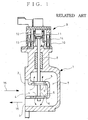
- Incorporated in the recirculation passage is an EGR valve as exemplarily shown in Fig. 1.
- reference numeral 1 denotes a housing which constitutes the EGR valve.
- the housing 1 has a side surface on which both a gas inlet 2 and a gas outlet 3 are opened one above the other, leading to gas intake and discharge pathways 4 and 7, respectively.
- the gas intake pathway 4 extending to the right in Fig. 1 ends with a dead end and has upper and lower openings 6 selectively opened and closed by upper and lower valve bodies 5.
- the gas discharge pathway 7 positioned under the lower opening 6 and extending to the right in Fig. 1 turns upward behind the dead end of the intake pathway 4, extends back to the left in Fig. 1 and ends with a dead end positioned over the upper opening 6.
- the upper and lower valve bodies 5 are supported by a valve stem 8 vertically and slidably extending through an upper portion of the housing 1, and are adapted to be upwardly fitted into the upper and lower openings 6 from below for closing of the same.
- an electromagnetic actuator 9 which actuates the valve stem 8 for its vertical motion to selectively open and close the openings 6 by the valve bodies 5. More specifically, the actuator 9 has a casing or outer shell 10 which vertically movably accommodates a core or iron piece 11 which in turn is fitted to an upper end of the valve stem 8 and is resiliently supported by upper and lower springs 12 and 13. The valve stem 8 can be moved upwardly or downwardly, using electro-magnetic force of a liner electromagnetic solenoid 14 surrounding the core 11 in the casing 10.
- valve bodies 5 can be electrically controlled to selectively open and close the openings 6 for starting and stopping the recirculation of the exhaust gas 15.
- the invention was made in view of the above and has its object to provide an EGR valve which is compact in size and which can increase an amount of exhaust gas to be recirculated more than is possible in the conventional art and without deteriorating mountability of the engine to a vehicle.
- an EGR valve comprising a housing with a mounting surface adapted to be joined to an exhaust gas confluence port on a suction pipe, a gas intake pathway extending through said housing along said mounting surface and having longitudinal ends one of which is opened as a gas inlet, gas discharge pathways extending through said housing to communicate with longitudinally spaced portions of said gas intake pathway via openings, each of said gas discharge pathways being opened as a gas outlet to said mounting surface, and actuator means mounted on said housing for moving valve bodies to selectively open and close said openings.
- opening operation of the valve bodies by the actuator means causes the exhaust gas from the exhaust side to be taken via the gas inlet of the housing into the gas intake pathway, the exhaust gas then flowing via the openings, which are on the longitudinally spaced portions of the gas intake pathway and are opened by the opening operation by the valve bodies, into the discharge pathways and is discharged via the gas outlets to the exhaust gas confluence port of the suction pipe.
- the openings in the longitudinal direction of the gas intake pathway can increase an amount of exhaust gas to be recirculated more than is possible in the conventional art; and moreover, the gas intake and discharge pathways provided by and within the one and single housing enables the exhaust gas introduced in the direction along with the mounting surface of the housing to be distributed into the plural openings so that it is discharged at the mounting surface of the housing to the exhaust gas confluence port of the suction pipe.
- any intervening, flow-path forming member is not necessitated with respect to the exhaust gas confluence port of the suction pipe and any protrusion of the EGR valves laterally outwardly of the vehicle is drastically suppressed so that deterioration of mountability of the engine to a vehicle is averted.
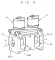
- Figs. 3-5 show an embodiment of the invention where parts similar to those shown in Figs. 1 and 2 are referred to by the same reference numerals.
- an EGR valve comprises a housing 24 having a mounting surface 25 adapted to be joined to an exhaust gas confluence port 18 on a suction pipe 17 (see Fig. 5).
- a gas intake pathway 27 and two gas discharge pathways 30.
- the gas intake pathway extends in a direction along the mounting surface 25 and has longitudinal ends one of which is opened as a gas inlet 26.
- the gas discharge pathways 30 are U-shaped in section and communicate with the gas intake pathway 27 at longitudinally spaced two positions via upper and lower openings 28.
- the gas discharge pathways 30 are opened as gas outlets 29 to the mounting surface 25.
- valve stems 32 which in turn slidably extend through the upper portion of the housing 24.
- Upper and lower valve bodies 33 on each of the valve stems 32 are selectively moved upwardly to and downwardly away from the corresponding upper and lower openings 28 so that the openings 28 at the two longitudinally spaced positions on the gas intake pathway 27 are selectively opened and closed.
- Each of the actuators 31, which is of a basic structure similar to that shown in Fig. 1, has a casing or outer shell 34 within which a core or iron piece 35 fitted to an upper end of the valve stem 32 is vertically movably accommodated and is resiliently supported by vertically extending springs 36 and 37 so that the valve stem 32 can be moved downwardly or upwardly, using electromagnetic force of a linear electromagnetic solenoid 38 which is arranged in the casing 34 to surround the core 35.
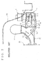
- an amount of the exhaust gas 15 to be recirculated is increased in comparison with the prior art without deteriorating mountablity of the engine to the vehicle.
- any interference between a side portion of a cab floor 20 with the EGR valve is averted so that restrictions in designing the EGR valve with increased amount of the exhaust gas 15 to be recirculated can be drastically relieved.
Landscapes
- Engineering & Computer Science (AREA)
- Chemical & Material Sciences (AREA)
- Combustion & Propulsion (AREA)
- Mechanical Engineering (AREA)
- General Engineering & Computer Science (AREA)
- Exhaust-Gas Circulating Devices (AREA)
- Fluid-Driven Valves (AREA)
Applications Claiming Priority (2)
| Application Number | Priority Date | Filing Date | Title |
|---|---|---|---|
| JP2002059025A JP2003254169A (ja) | 2002-03-05 | 2002-03-05 | Egrバルブ |
| JP2002059025 | 2002-03-05 |
Publications (3)
| Publication Number | Publication Date |
|---|---|
| EP1342908A2 true EP1342908A2 (fr) | 2003-09-10 |
| EP1342908A3 EP1342908A3 (fr) | 2003-11-26 |
| EP1342908B1 EP1342908B1 (fr) | 2006-05-10 |
Family
ID=27751080
Family Applications (1)
| Application Number | Title | Priority Date | Filing Date |
|---|---|---|---|
| EP20030004620 Expired - Lifetime EP1342908B1 (fr) | 2002-03-05 | 2003-03-03 | Soupape egr |
Country Status (4)
| Country | Link |
|---|---|
| US (1) | US20030168111A1 (fr) |
| EP (1) | EP1342908B1 (fr) |
| JP (1) | JP2003254169A (fr) |
| DE (1) | DE60305086T2 (fr) |
Cited By (4)
| Publication number | Priority date | Publication date | Assignee | Title |
|---|---|---|---|---|
| WO2007028381A2 (fr) * | 2005-09-08 | 2007-03-15 | Behr Gmbh & Co. Kg | Dispositif destine a commander un flux de gaz d'echappement |
| WO2007134962A1 (fr) * | 2006-05-19 | 2007-11-29 | Mahle International Gmbh | Ensemble de soupapes pour système de recyclage des gaz d'échappement |
| EP1918566A2 (fr) * | 2006-10-31 | 2008-05-07 | International Engine Intellectual Property Company, LLC. | Clapet de recirculation de gaz d'échappement (EGR) de moteur |
| GB2484481A (en) * | 2010-10-12 | 2012-04-18 | Gm Global Tech Operations Inc | EGR valve assembly for internal combustion engines |
Families Citing this family (2)
| Publication number | Priority date | Publication date | Assignee | Title |
|---|---|---|---|---|
| US9273450B2 (en) | 2012-06-22 | 2016-03-01 | Kohler Mira Limited | Plumbing fixture with heating elements |
| GB2568271B (en) | 2017-11-09 | 2020-04-22 | Kohler Mira Ltd | A plumbing component for controlling the mixture of two supplies of water |
Citations (5)
| Publication number | Priority date | Publication date | Assignee | Title |
|---|---|---|---|---|
| DE4204434A1 (de) * | 1992-02-14 | 1993-08-19 | Pierburg Gmbh | Steuerventil fuer abgasrueckfuehrung |
| US5927257A (en) * | 1997-09-19 | 1999-07-27 | Caterpillar Inc | Pressure compensating exhaust gas recirculation valve |
| US6006732A (en) * | 1998-09-03 | 1999-12-28 | Navistar International Transportation Corp | Balanced flow EGR control apparatus |
| WO2001083975A1 (fr) * | 2000-05-03 | 2001-11-08 | Cooperstandard Automotive Fluid Systems | Appareil de soupape rge |
| US20010048093A1 (en) * | 1999-08-04 | 2001-12-06 | Mannesmann Vdo Ag | Control valve |
-
2002
- 2002-03-05 JP JP2002059025A patent/JP2003254169A/ja active Pending
-
2003
- 2003-03-03 EP EP20030004620 patent/EP1342908B1/fr not_active Expired - Lifetime
- 2003-03-03 DE DE2003605086 patent/DE60305086T2/de not_active Expired - Lifetime
- 2003-03-05 US US10/378,916 patent/US20030168111A1/en not_active Abandoned
Patent Citations (5)
| Publication number | Priority date | Publication date | Assignee | Title |
|---|---|---|---|---|
| DE4204434A1 (de) * | 1992-02-14 | 1993-08-19 | Pierburg Gmbh | Steuerventil fuer abgasrueckfuehrung |
| US5927257A (en) * | 1997-09-19 | 1999-07-27 | Caterpillar Inc | Pressure compensating exhaust gas recirculation valve |
| US6006732A (en) * | 1998-09-03 | 1999-12-28 | Navistar International Transportation Corp | Balanced flow EGR control apparatus |
| US20010048093A1 (en) * | 1999-08-04 | 2001-12-06 | Mannesmann Vdo Ag | Control valve |
| WO2001083975A1 (fr) * | 2000-05-03 | 2001-11-08 | Cooperstandard Automotive Fluid Systems | Appareil de soupape rge |
Cited By (10)
| Publication number | Priority date | Publication date | Assignee | Title |
|---|---|---|---|---|
| WO2007028381A2 (fr) * | 2005-09-08 | 2007-03-15 | Behr Gmbh & Co. Kg | Dispositif destine a commander un flux de gaz d'echappement |
| WO2007028381A3 (fr) * | 2005-09-08 | 2007-05-10 | Behr Gmbh & Co Kg | Dispositif destine a commander un flux de gaz d'echappement |
| US7938106B2 (en) | 2005-09-08 | 2011-05-10 | Behr Gmbh & Co. Kg | Device for controlling an exhaust gas stream |
| WO2007134962A1 (fr) * | 2006-05-19 | 2007-11-29 | Mahle International Gmbh | Ensemble de soupapes pour système de recyclage des gaz d'échappement |
| US8225773B2 (en) | 2006-05-19 | 2012-07-24 | Mahle International Gmbh | Valve arrangement for an exhaust gas recirculation device |
| EP1918566A2 (fr) * | 2006-10-31 | 2008-05-07 | International Engine Intellectual Property Company, LLC. | Clapet de recirculation de gaz d'échappement (EGR) de moteur |
| EP1918566A3 (fr) * | 2006-10-31 | 2009-01-28 | International Engine Intellectual Property Company, LLC. | Clapet de recirculation de gaz d'échappement (EGR) de moteur |
| GB2484481A (en) * | 2010-10-12 | 2012-04-18 | Gm Global Tech Operations Inc | EGR valve assembly for internal combustion engines |
| US8763592B2 (en) | 2010-10-12 | 2014-07-01 | GM Global Technology Operations LLC | EGR valve assembly for internal combustion engines |
| GB2484481B (en) * | 2010-10-12 | 2015-03-04 | Gm Global Tech Operations Inc | EGR valve assembly for internal combustion engines |
Also Published As
| Publication number | Publication date |
|---|---|
| EP1342908B1 (fr) | 2006-05-10 |
| DE60305086D1 (de) | 2006-06-14 |
| EP1342908A3 (fr) | 2003-11-26 |
| DE60305086T2 (de) | 2006-11-09 |
| US20030168111A1 (en) | 2003-09-11 |
| JP2003254169A (ja) | 2003-09-10 |
Similar Documents
| Publication | Publication Date | Title |
|---|---|---|
| CN102257257B (zh) | 进气装置 | |
| EP0985819B1 (fr) | Agencement de pompe à carburant et de soupape RGE dans un moteur à injection directe de carburant | |
| CN104329195B (zh) | 带有egr‑气流分配的发动机进气歧管 | |
| US20050235973A1 (en) | Exhaust gas recirculation system for a combustion engine | |
| CN102725504B (zh) | 气体供给模块,包括该模块的组件,以及包括该模块的发动机 | |
| EP3438433B1 (fr) | Dispositif du type moteur | |
| KR101612148B1 (ko) | 듀얼 가변 밸브 솔레노이드 모듈 | |
| JP6026825B2 (ja) | 内燃機関の吸気装置 | |
| CN106762239B (zh) | 排气再循环装置 | |
| US5690081A (en) | Cylinder head for a liquid-cooled multi-cylinder internal combustion engine | |
| CN101495743A (zh) | 用于废气再循环装置的阀装置 | |
| US6032634A (en) | Air induction system for internal-combustion engine | |
| EP3438438B1 (fr) | Dispositif de moteur | |
| KR102169316B1 (ko) | Egr 밸브 유닛 및 이를 갖는 배기가스 재순환 시스템 | |
| US5704326A (en) | Air induction system for internal-combustion engine | |
| CN102667095B (zh) | 机动车辆发动机盖和热交换器之间的接口部件、接口部件和滑阀的组件以及用于发动机的气体供应模块 | |
| US6823823B2 (en) | Water jacket structure for cylinder block and cylinder head of an engine with a split cooling system adapted therein | |
| US6209501B1 (en) | Suction system for internal combustion engine | |
| EP1342908B1 (fr) | Soupape egr | |
| US6928994B2 (en) | Modular exhaust gas recirculation assembly | |
| KR100194532B1 (ko) | 내연기관의 흡기장치 | |
| CN107725145B (zh) | 一种曲轴箱通风系统 | |
| JP2005226585A (ja) | エンジンの吸気装置 | |
| US10851742B2 (en) | Intake system for vehicle | |
| JP2019143531A (ja) | 内燃機関の流体制御装置 |
Legal Events
| Date | Code | Title | Description |
|---|---|---|---|
| PUAI | Public reference made under article 153(3) epc to a published international application that has entered the european phase |
Free format text: ORIGINAL CODE: 0009012 |
|
| AK | Designated contracting states |
Kind code of ref document: A2 Designated state(s): AT BE BG CH CY CZ DE DK EE ES FI FR GB GR HU IE IT LI LU MC NL PT SE SI SK TR |
|
| AX | Request for extension of the european patent |
Extension state: AL LT LV MK RO |
|
| PUAL | Search report despatched |
Free format text: ORIGINAL CODE: 0009013 |
|
| AK | Designated contracting states |
Kind code of ref document: A3 Designated state(s): AT BE BG CH CY CZ DE DK EE ES FI FR GB GR HU IE IT LI LU MC NL PT SE SI SK TR |
|
| AX | Request for extension of the european patent |
Extension state: AL LT LV MK RO |
|
| 17P | Request for examination filed |
Effective date: 20040403 |
|
| 17Q | First examination report despatched |
Effective date: 20040701 |
|
| AKX | Designation fees paid |
Designated state(s): DE FR SE |
|
| GRAP | Despatch of communication of intention to grant a patent |
Free format text: ORIGINAL CODE: EPIDOSNIGR1 |
|
| GRAS | Grant fee paid |
Free format text: ORIGINAL CODE: EPIDOSNIGR3 |
|
| GRAA | (expected) grant |
Free format text: ORIGINAL CODE: 0009210 |
|
| AK | Designated contracting states |
Kind code of ref document: B1 Designated state(s): DE FR SE |
|
| REF | Corresponds to: |
Ref document number: 60305086 Country of ref document: DE Date of ref document: 20060614 Kind code of ref document: P |
|
| PG25 | Lapsed in a contracting state [announced via postgrant information from national office to epo] |
Ref country code: SE Free format text: LAPSE BECAUSE OF FAILURE TO SUBMIT A TRANSLATION OF THE DESCRIPTION OR TO PAY THE FEE WITHIN THE PRESCRIBED TIME-LIMIT Effective date: 20060810 |
|
| ET | Fr: translation filed | ||
| PLBE | No opposition filed within time limit |
Free format text: ORIGINAL CODE: 0009261 |
|
| STAA | Information on the status of an ep patent application or granted ep patent |
Free format text: STATUS: NO OPPOSITION FILED WITHIN TIME LIMIT |
|
| 26N | No opposition filed |
Effective date: 20070213 |
|
| PGFP | Annual fee paid to national office [announced via postgrant information from national office to epo] |
Ref country code: FR Payment date: 20080228 Year of fee payment: 6 |
|
| REG | Reference to a national code |
Ref country code: FR Ref legal event code: ST Effective date: 20091130 |
|
| PG25 | Lapsed in a contracting state [announced via postgrant information from national office to epo] |
Ref country code: FR Free format text: LAPSE BECAUSE OF NON-PAYMENT OF DUE FEES Effective date: 20091123 |
|
| PGFP | Annual fee paid to national office [announced via postgrant information from national office to epo] |
Ref country code: DE Payment date: 20150516 Year of fee payment: 13 |
|
| REG | Reference to a national code |
Ref country code: DE Ref legal event code: R119 Ref document number: 60305086 Country of ref document: DE |
|
| PG25 | Lapsed in a contracting state [announced via postgrant information from national office to epo] |
Ref country code: DE Free format text: LAPSE BECAUSE OF NON-PAYMENT OF DUE FEES Effective date: 20161001 |