EP1342878B1 - Metallischer Schrank mit vertikalem Vorhang und integrierten Stützplatten - Google Patents
Metallischer Schrank mit vertikalem Vorhang und integrierten Stützplatten Download PDFInfo
- Publication number
- EP1342878B1 EP1342878B1 EP20030290566 EP03290566A EP1342878B1 EP 1342878 B1 EP1342878 B1 EP 1342878B1 EP 20030290566 EP20030290566 EP 20030290566 EP 03290566 A EP03290566 A EP 03290566A EP 1342878 B1 EP1342878 B1 EP 1342878B1
- Authority
- EP
- European Patent Office
- Prior art keywords
- flange
- cabinet
- side wall
- space
- single piece
- Prior art date
- Legal status (The legal status is an assumption and is not a legal conclusion. Google has not performed a legal analysis and makes no representation as to the accuracy of the status listed.)
- Expired - Lifetime
Links
- 239000002184 metal Substances 0.000 title claims description 6
- 238000004519 manufacturing process Methods 0.000 claims description 5
- 238000003466 welding Methods 0.000 claims description 5
- 238000007592 spray painting technique Methods 0.000 claims description 2
- 230000004308 accommodation Effects 0.000 claims 1
- 238000010422 painting Methods 0.000 description 8
- 239000003973 paint Substances 0.000 description 6
- 208000031968 Cadaver Diseases 0.000 description 2
- 238000000034 method Methods 0.000 description 2
- 238000003860 storage Methods 0.000 description 2
- 239000000725 suspension Substances 0.000 description 2
- 235000004443 Ricinus communis Nutrition 0.000 description 1
- 240000000528 Ricinus communis Species 0.000 description 1
- 238000005452 bending Methods 0.000 description 1
- 210000004907 gland Anatomy 0.000 description 1
- 238000009434 installation Methods 0.000 description 1
- 238000012986 modification Methods 0.000 description 1
- 230000004048 modification Effects 0.000 description 1
- 230000000717 retained effect Effects 0.000 description 1
Images


Classifications
-
- E—FIXED CONSTRUCTIONS
- E06—DOORS, WINDOWS, SHUTTERS, OR ROLLER BLINDS IN GENERAL; LADDERS
- E06B—FIXED OR MOVABLE CLOSURES FOR OPENINGS IN BUILDINGS, VEHICLES, FENCES OR LIKE ENCLOSURES IN GENERAL, e.g. DOORS, WINDOWS, BLINDS, GATES
- E06B9/00—Screening or protective devices for wall or similar openings, with or without operating or securing mechanisms; Closures of similar construction
- E06B9/02—Shutters, movable grilles, or other safety closing devices, e.g. against burglary
- E06B9/08—Roll-type closures
- E06B9/11—Roller shutters
- E06B9/115—Roller shutters specially adapted for furniture
-
- A—HUMAN NECESSITIES
- A47—FURNITURE; DOMESTIC ARTICLES OR APPLIANCES; COFFEE MILLS; SPICE MILLS; SUCTION CLEANERS IN GENERAL
- A47B—TABLES; DESKS; OFFICE FURNITURE; CABINETS; DRAWERS; GENERAL DETAILS OF FURNITURE
- A47B47/00—Cabinets, racks or shelf units, characterised by features related to dismountability or building-up from elements
- A47B47/02—Cabinets, racks or shelf units, characterised by features related to dismountability or building-up from elements made of metal only
Definitions
- the invention relates to monobloc metal cabinets with vertical curtains having high rigidity.
- Monobloc cabinets are already known, so called because they include a bottom, side walls, a top and a base which form a one-piece body. In the case of metal cabinets, this one-piece body is welded.
- One-piece cabinets with hinged doors include at least one door that pivots about a vertical axis. Their disadvantage is that the opening of the doors requires a large available space in the direction of the depth. These cabinets can not be installed in narrow corridors.
- Folding door monobloc cabinets include at least one door that can be folded into two parts in general. The installation of these cabinets requires a smaller aisle width than cabinets with hinged doors. However, when the door is open, the two superposed door parts interfere with access to the ends of the storage shelves housed in these cabinets.
- Monobloc cabinets with sliding doors are provided with at least two doors that slide in close parallel planes. Their disadvantage is that a part of the opening, of width equal to a door, is always closed.
- the curtains can be of horizontal type (sliding in vertical direction) or of vertical type (sliding in horizontal direction). Each curtain is housed in a space between a wall (upper-lower or side) and a cheek incorporated inside the one-piece body.
- the invention relates to monobloc cabinets of the vertical curtain type, comprising a single curtain or two curtains moving in the horizontal direction.
- two cheeks previously painted which are parallel to the side walls, are incorporated at a distance from these walls and are fixed on the one hand to the base and on the other hand to above the cabinet.
- the space between each cheek and the adjacent side wall is used to accommodate a curtain in the open position of the cabinet.
- the object of the invention is to eliminate this lateral floating of the cheeks.
- the document NL-A-9301754 discloses a curtain cabinet according to the preamble of claim 1.
- the invention also aims to simplify the painting of the cabinet and reduce the cost of painting.
- the invention implements the fastening of the cheeks by welding to the one-piece body, without however preventing the subsequent mounting of the guide rails, by welding only their rear vertical edge, that is to say the edge closest to the bottom, so that the elasticity of the cheeks themselves allows deformation for the passage of the guide rails.
- a first advantage of this arrangement is that the high rigidity obtained completely eliminates the floating of the cheeks, so that the shelves that support the loads in the cabinet can not move laterally. This rigidity can be obtained even if the cheeks are simply stuck in high and low positions, without the use of fixing screws.
- a second advantage of this provision is a significant reduction in the cost of manufacturing the cabinet. Indeed, since the welding operations are obligatorily carried out before the painting operations, the cheeks are incorporated into the one-piece body before the painting thereof, and a single painting operation is used for the body of the cabinet, including cheeks.
- the first reason for this cost reduction is that it is not necessary to paint the body and each cheek separately, and that a single painting operation is sufficient.
- Another advantage of this arrangement is that, in a variant in which the cheek comprises a vertical rear fold whose edge is welded in front of the bottom, so that there remains a space between the fold and the bottom, a hidden chute passage of cables can be easily performed in the cabinet at the back of each cheek, without increasing the manufacturing price.
- the invention relates to a vertical wall monobloc metal cabinet, of the type which comprises a welded monobloc body having a bottom, side walls, a top and a base, the cabinet further comprising at least one cheek disposed parallel to a side wall and delimiting between it and the side wall adjacent, a housing space of a vertical curtain horizontally movable in a guiding device, so that the curtain is retractable in this space delimited between the side wall and the cheek; according to the invention, the cheek is welded to the one-piece body over most of at least its vertical edge closest to the bottom, so that the cheek is incorporated in the one-piece body.
- the cabinet comprises two vertical curtains and two cheeks each arranged parallel to one of the side walls, each cheek delimiting between it and the adjacent side wall a housing space of a vertical curtain.
- the cheek forms a vertical fold at its near end, the fold being turned towards the adjacent side wall so that it separates the curtain housing space, turned forwards , a vertical space facing back and between the fold and the bottom, this space opening towards the center of the cabinet.
- the fold of the cheek is welded to the side wall or the bottom, at the connection between the bottom and the side wall.
- the fold of the cheek carries an accessory hooking device.
- the attachment device may comprise a line of holes aligned parallel to the vertical edge of the cheek.
- the base is provided with a cross member at each lateral end of the cabinet, each crossmember has two holes for height adjustment cylinders, and each crossmember cooperates with a wheeled support which comprises a support body intended to be applied under the crossbar and to be fixed to the crossmember by cylinder mounting holes, the support body being provided with two roller support pins, and two swivel castors each mounted on one of the axes.
- each front wheel is provided with a locking brake.
- the one-piece body comprises, in at least one part selected from the sidewalls and the bottom, at least one gland opening.
- the cabinet also comprises a grommet connector disposed in a grommet opening and intended to penetrate through a grommet of another adjacent cabinet, so that the two cabinets can be secured by the connector .
- the figure 1 represents a cabinet with vertical curtains, whose curtains have been removed.
- the cabinet 10 comprises a one-piece body consisting of two side walls 12, a cabinet top 14, a bottom 16 and a base 18. These elements form a one-piece body.
- the cabinet 10 shown on the figure 1 has, on each side, a cheek 20 which is not removable.
- the cheek 20 has its front edge 24 which is distant from the front of the side wall and leaves an opening 25 between the cheek and the side wall for the passage of a curtain.
- the cheek comprises alignments of orifices 22, called racks, for fixing shelf storage support accessories.
- the cheek 20 has, at its rear part near the bottom, a fold 26 whose size corresponds to the width of the space for accommodating the curtain in the open position thereof. This space is thus closed by the side wall, the cheek and the fold 26 thereof, and it is partially open at the front, through the opening 25 between the edge 24 and the side wall.
- the end of the fold 26 opposite the cheek 20 has a flap 28 to be welded to the side wall or the bottom so that the cheek is integral with the one-piece body.
- the flap 28 has almost the entire height of the cheek and thus ensures a robust attachment thereof.
- the cheek 20 does not reach the bottom 16. Indeed, there is a space 30, opening towards the central part of the cabinet and intended to form a cable duct.
- shelves 32 and sliding frames 34 which may constitute cabinet accessories extend to the bottom, and therefore have a part that closes the space 30 delimited behind the cheek. As a result, the cables placed in this chute space are retained therein.
- an alignment of orifices, not shown but similar to a rack 22, may be intended for attaching accessories, for example cable retaining members.
- the figure 1 also indicates that the cabinet has, in the upper and lower parts, orifices 36 provided with grommets, communicating with the space forming chute 30.
- each space 30 can communicate with a chute incorporated in the base.
- connection can be made by passing cables through the grommets 36 indicated on the figure 1 .
- the cables can then be guided into the side chutes between the back of the cheeks and the bottom, and connected to the equipment placed in the cabinet.
- a cable-fitting connection (not shown), disposed in a cable-entry hole 36, is intended to penetrate through a gill-hole of another adjacent cabinet, so that the two cabinets can be secured by this connection.
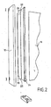
- the figure 3 represents in exploded form a mounting device of a cabinet so that it can be moved.
- the base 18 comprises a cross member 38 having holes 40 normally intended for mounting height adjustment cylinders.
- the cross member 38 has tabs protruding upwardly to retain the corresponding cheek outwardly.
- Each jack is screwed into a nut welded preferably on the crossbar 38, in front of the holes 40.
- the jacks are removed and a caster support having a body 42 is disposed opposite the cross member 38 so that, through holes 44, it can be attached to the cylinder mounting nuts of the cross member 38.
- rollers 48 can be snapped onto rotation axes 46 which are fixed to the support 42.
- the casters placed at the front of the cabinet have a brake 50.
- the invention therefore relates to a cabinet of high rigidity, which can be provided with wiring and which can however be moved on wheels.
- a cabinet is useful as a "nomadic" cabinet, that is to say intended for staff whose presence in the company is reduced, in premises that are however constantly used by rotating staff.
- the entire one-piece body, including the cheeks is suspended by its base 18 and passes through a paint line.
- the one-piece body is painted in one pass. Indeed, all the apparent surfaces of the cabinet are coated.
- the paint hardly penetrates into this space.
- the cheek surface facing the sidewall and the inner sidewall surface are substantially unpainted.
- each cheek which is welded only to the rear on the bottom, may be elastically spaced from the side wall so that the opening 25 widens sufficiently for the passage of the rails. guide. Then, the cheeks can be fixed in position in any convenient manner, for example by screwing or mechanical jamming.
Landscapes
- Engineering & Computer Science (AREA)
- Structural Engineering (AREA)
- Architecture (AREA)
- Civil Engineering (AREA)
- Drawers Of Furniture (AREA)
- Curtains And Furnishings For Windows Or Doors (AREA)
Claims (10)
- Metallschrank in Blockkonstruktion mit vertikalem Rollladen vom Typ mit einem geschweißten Körper in Blockkonstruktion, aufweisend eine Rückseite (16), Seitenwände (12), ein Oberteil (14) und ein Fußgestell (18), wobei der Schrank des Weiteren mindestens ein Seitenteil (20) aufweist, das parallel zu einer Seitenwand (12) angeordnet ist, wobei das Seitenteil (20) zwischen sich und der angrenzenden Seitenwand (12) einen Aufnahmeraum für einen in einer Führungsvorrichtung horizontal beweglichen vertikalen Rollladen begrenzt, damit der Rollladen in diesem zwischen der Seitenwand (12) und dem Seitenteil (20) begrenzten Raum einziehbar ist, dadurch gekennzeichnet, dass das Seitenteil (20) nur an dem größten Teil zumindest seines vertikalen Seitenrands, der der Rückseite (16) am nächsten ist, an den Körper in Blockkonstruktion geschweißt ist, so dass das Seitenteil (20) in dem Körper in Blockkonstruktion eingebaut ist und dass die Elastizität des Seitenteils selber eine Verformung für den Durchgang der Führungsschienen erlaubt.
- Schrank nach Anspruch 1, dadurch gekennzeichnet, dass er zwei vertikale Rollläden und zwei Seitenteile (20) aufweist, die jeweils parallel zu einer der Seitenwände (12) angeordnet sind, wobei jedes Seitenteil (20) zwischen sich und der angrenzenden Seitenwand (12) einen Aufnahmeraum eines vertikalen Rollladens begrenzt.
- Schrank nach einem der Ansprüche 1 und 2, dadurch gekennzeichnet, dass das Seitenteil (20) einen vertikalen Umschlag (26) an seinem Teil nahe der Rückseite bildet, wobei der Umschlag (26) zur angrenzenden Seitenwand (12) weist, um den Aufnahmeraum für den Rollladen, der nach vorne weist, von einem vertikalen Raum (30) zu trennen, der nach hinten weist und zwischen dem Umschlag und der Rückseite vorgesehen ist, wobei dieser Raum (30) in der Mitte des Schranks mündet.
- Schrank nach Anspruch 3, dadurch gekennzeichnet, dass der Umschlag (26) des Seitenteils an dem Verbindungsstück zwischen Rückseite (16) und Seitenwand (12) verschweißt ist.
- Schrank nach einem der Ansprüche 3 und 4, dadurch gekennzeichnet, dass der Umschlag (26) des Seitenteils eine Einhängevorrichtung für Zubehör aufweist.
- Schrank nach einem der vorhergehenden Ansprüche, dadurch gekennzeichnet, dass das Fußgestell (18) an jedem seitlichen Ende des Schranks mit einer Querstrebe (38) versehen ist, jede Querstrebe (38) zwei Löcher (40) aufweist, die für Höhenverstellschrauben vorgesehen sind, und jede Querstrebe (38) mit einem Rollenhalter zusammenwirkt, der einen Haltekörper (42) aufweist, der dafür vorgesehen ist, unter der Querstrebe angebracht zu werden, wobei er durch ein Schraubenloch an der Querstrebe befestigt und mit zwei Rollenhalterachsen (46) sowie mit zwei verstellbaren Rollen (48), die jeweils auf einer der Achsen montiert sind, versehen ist.
- Schrank nach Anspruch 6, dadurch gekennzeichnet, dass jede Frontrolle (48) mit einer Feststellbremse (50) versehen ist.
- Schrank nach einem der vorhergehenden Ansprüche, dadurch gekennzeichnet, dass der Körper in Blockkonstruktion in einem Teil, der mindestens aus den Seitenwänden (12) und der Rückseite (16) ausgewählt ist, mindestens eine Kabeldurchführungsöffnung (36) aufweist.
- Schrank nach Anspruch 8, dadurch gekennzeichnet, dass er des Weiteren ein Kabeldurchführungs-Verbindungsstück aufweist, das in einer Kabeldurchführungsöffnung (36) der Seitenwand angeordnet und dafür gedacht ist, in eine Kabeldurchführungsöffnung eines weiteren, angrenzenden Schranks eingebracht zu werden, so dass die beiden Schränke durch das Verbindungsstück verbunden sind.
- Verfahren zur Herstellung eines Schranks in Blockkonstruktion nach einem der vorhergehenden Ansprüche, dadurch gekennzeichnet, dass dieses folgendes umfasst:- Schweißen von mindestens einem Seitenteil (20) an den Körper in Blockkonstruktion,- Aufhängen des Körpers in Blockkonstruktion, der das geschweißte Seitenteil (20) enthält, durch Befestigung an einer Stelle zumindest des Fußgestells (18), und- Aufbringen von Anstrich auf die sichtbaren Oberflächen durch Spritzen,so dass die Innenflächen des Raums für die Rollladenaufnahme, gebildet zwischen dem Seitenteil (20) und der angrenzenden Seitenwand (12), nicht lackiert sind.
Applications Claiming Priority (2)
| Application Number | Priority Date | Filing Date | Title |
|---|---|---|---|
| FR0202904 | 2002-03-07 | ||
| FR0202904A FR2836803B1 (fr) | 2002-03-07 | 2002-03-07 | Armoire metallique monobloc a rideau vertical a joues de support integrees |
Publications (2)
| Publication Number | Publication Date |
|---|---|
| EP1342878A1 EP1342878A1 (de) | 2003-09-10 |
| EP1342878B1 true EP1342878B1 (de) | 2014-12-03 |
Family
ID=27741458
Family Applications (1)
| Application Number | Title | Priority Date | Filing Date |
|---|---|---|---|
| EP20030290566 Expired - Lifetime EP1342878B1 (de) | 2002-03-07 | 2003-03-07 | Metallischer Schrank mit vertikalem Vorhang und integrierten Stützplatten |
Country Status (2)
| Country | Link |
|---|---|
| EP (1) | EP1342878B1 (de) |
| FR (1) | FR2836803B1 (de) |
Families Citing this family (1)
| Publication number | Priority date | Publication date | Assignee | Title |
|---|---|---|---|---|
| RU2402251C2 (ru) * | 2007-06-15 | 2010-10-27 | Сергей Васильевич Крылов | Сборно-разборный стеллаж (варианты) |
Family Cites Families (5)
| Publication number | Priority date | Publication date | Assignee | Title |
|---|---|---|---|---|
| GB885999A (en) * | 1959-08-22 | 1962-01-03 | Evertaut Ltd | Improvements relating to shutter assemblies |
| US6550879B1 (en) * | 1992-12-01 | 2003-04-22 | Herman Milles, Inc. | Cabinet structure |
| US5372175A (en) * | 1993-06-10 | 1994-12-13 | Waterloo Industries, Inc. | Tambour door construction |
| NL9301754A (nl) * | 1993-10-11 | 1995-05-01 | Lensvelt B V | Schuifdeurkast. |
| DE19504074C1 (de) * | 1995-02-08 | 1996-05-02 | Steinco Paul Vom Stein Gmbh | Doppelrolle für Apparate, Möbel od. dgl. |
-
2002
- 2002-03-07 FR FR0202904A patent/FR2836803B1/fr not_active Expired - Lifetime
-
2003
- 2003-03-07 EP EP20030290566 patent/EP1342878B1/de not_active Expired - Lifetime
Also Published As
| Publication number | Publication date |
|---|---|
| FR2836803B1 (fr) | 2004-10-08 |
| EP1342878A1 (de) | 2003-09-10 |
| FR2836803A1 (fr) | 2003-09-12 |
Similar Documents
| Publication | Publication Date | Title |
|---|---|---|
| FR2636219A1 (fr) | Agencement de meuble dans une construction et vehicule, tel que caravane, comprenant un meuble mobile | |
| CA2974978A1 (fr) | Dispositif pour la pose ou la depose d'une vitre de vehicule automobile | |
| EP3296154A1 (de) | Beladevorrichtung mit schiebeplattform | |
| EP1342878B1 (de) | Metallischer Schrank mit vertikalem Vorhang und integrierten Stützplatten | |
| FR2699255A1 (fr) | Chevalet modulable plus spécialement destiné à supporter des pièces détachées, en particulier des éléments de carrosserie dans le cadre de l'industrie automobile. | |
| FR2961245A1 (fr) | Dispositif de guidage pour porte coulissante escamotable comprenant un rail demontable | |
| EP1925236A1 (de) | Ordnungsvorrichtung, die zwischen Hoch- und Tiefposition umstellbar ist | |
| EP1342879B1 (de) | Einstückiger Metallschrank mit vertikalem Vorhang und verstärktem Sockel und Stützrollen | |
| EP0036817B1 (de) | Innere Einrichtung für ein Fahrzeug, z.B. für einen faltbaren Wohnwagen | |
| EP2253562B1 (de) | Transportvorrichtung für vorgefertigte plattenförmige Elemente | |
| FR2940235A1 (fr) | Ecarteur pour porte de vehicule automobile | |
| FR2733728A1 (fr) | Cache-bagages pour vehicule automobile | |
| EP3000354B1 (de) | Vorrichtung zum Lagern von Gegenständen für Garage oder Ähnliches | |
| EP0575263B1 (de) | Rinne für elektrische Stromversorgungsvorrichtung | |
| EP4105419B1 (de) | Perfektionierte vorrichtung zum provisorischen schliessen eines öffnungselements auf einem halterungselement | |
| FR2615835A1 (fr) | Assemblage d'un capot retractable et de guides et capot telescopique pour une structure de stockage | |
| EP1093971A1 (de) | Lastenträger für ein Kraftfahrzeug und Kraftfahrzeug mit solchem Träger | |
| FR3117074A1 (fr) | Dispositif de support a tablette mobile multi positions et module de rangement equipe d’un tel dispositif | |
| FR2869633A1 (fr) | Dispositif de montage d'une porte de vehicule automobile. | |
| EP3508093A1 (de) | Demontierbare vorrichtung zum materialtransport | |
| FR2730614A1 (fr) | Meuble a tiroirs anti-basculement | |
| FR2809073A1 (fr) | Face avant pour vehicule automobile et bloc avant correspondant | |
| FR2816902A1 (fr) | Habillage pour colonne de direction | |
| EP0008978A1 (de) | Fahrzeug, insbesondere Wohnwagen, mit einem Klappmöbel | |
| EP1637378B1 (de) | Einbaueinheit mit abnehmbaren Dachdeckel und abnehmbaren Windabweiser für KFZ-Dächer |
Legal Events
| Date | Code | Title | Description |
|---|---|---|---|
| PUAI | Public reference made under article 153(3) epc to a published international application that has entered the european phase |
Free format text: ORIGINAL CODE: 0009012 |
|
| AK | Designated contracting states |
Kind code of ref document: A1 Designated state(s): AT BE BG CH CY CZ DE DK EE ES FI FR GB GR HU IE IT LI LU MC NL PT RO SE SI SK TR |
|
| AX | Request for extension of the european patent |
Extension state: AL LT LV MK |
|
| 17P | Request for examination filed |
Effective date: 20040304 |
|
| AKX | Designation fees paid |
Designated state(s): AT BE BG CH CY CZ DE DK EE ES FI FR GB GR HU IE IT LI LU MC NL PT RO SE SI SK TR |
|
| 17Q | First examination report despatched |
Effective date: 20060904 |
|
| GRAP | Despatch of communication of intention to grant a patent |
Free format text: ORIGINAL CODE: EPIDOSNIGR1 |
|
| INTG | Intention to grant announced |
Effective date: 20140623 |
|
| GRAS | Grant fee paid |
Free format text: ORIGINAL CODE: EPIDOSNIGR3 |
|
| GRAA | (expected) grant |
Free format text: ORIGINAL CODE: 0009210 |
|
| AK | Designated contracting states |
Kind code of ref document: B1 Designated state(s): AT BE BG CH CY CZ DE DK EE ES FI FR GB GR HU IE IT LI LU MC NL PT RO SE SI SK TR |
|
| REG | Reference to a national code |
Ref country code: GB Ref legal event code: FG4D Free format text: NOT ENGLISH |
|
| REG | Reference to a national code |
Ref country code: AT Ref legal event code: REF Ref document number: 699499 Country of ref document: AT Kind code of ref document: T Effective date: 20141215 Ref country code: CH Ref legal event code: EP |
|
| REG | Reference to a national code |
Ref country code: IE Ref legal event code: FG4D Free format text: LANGUAGE OF EP DOCUMENT: FRENCH |
|
| REG | Reference to a national code |
Ref country code: DE Ref legal event code: R096 Ref document number: 60347060 Country of ref document: DE Effective date: 20150115 |
|
| REG | Reference to a national code |
Ref country code: FR Ref legal event code: PLFP Year of fee payment: 13 |
|
| REG | Reference to a national code |
Ref country code: NL Ref legal event code: VDEP Effective date: 20141203 |
|
| REG | Reference to a national code |
Ref country code: AT Ref legal event code: MK05 Ref document number: 699499 Country of ref document: AT Kind code of ref document: T Effective date: 20141203 |
|
| PG25 | Lapsed in a contracting state [announced via postgrant information from national office to epo] |
Ref country code: FI Free format text: LAPSE BECAUSE OF FAILURE TO SUBMIT A TRANSLATION OF THE DESCRIPTION OR TO PAY THE FEE WITHIN THE PRESCRIBED TIME-LIMIT Effective date: 20141203 Ref country code: NL Free format text: LAPSE BECAUSE OF FAILURE TO SUBMIT A TRANSLATION OF THE DESCRIPTION OR TO PAY THE FEE WITHIN THE PRESCRIBED TIME-LIMIT Effective date: 20141203 Ref country code: ES Free format text: LAPSE BECAUSE OF FAILURE TO SUBMIT A TRANSLATION OF THE DESCRIPTION OR TO PAY THE FEE WITHIN THE PRESCRIBED TIME-LIMIT Effective date: 20141203 |
|
| PG25 | Lapsed in a contracting state [announced via postgrant information from national office to epo] |
Ref country code: CY Free format text: LAPSE BECAUSE OF FAILURE TO SUBMIT A TRANSLATION OF THE DESCRIPTION OR TO PAY THE FEE WITHIN THE PRESCRIBED TIME-LIMIT Effective date: 20141203 Ref country code: AT Free format text: LAPSE BECAUSE OF FAILURE TO SUBMIT A TRANSLATION OF THE DESCRIPTION OR TO PAY THE FEE WITHIN THE PRESCRIBED TIME-LIMIT Effective date: 20141203 Ref country code: SE Free format text: LAPSE BECAUSE OF FAILURE TO SUBMIT A TRANSLATION OF THE DESCRIPTION OR TO PAY THE FEE WITHIN THE PRESCRIBED TIME-LIMIT Effective date: 20141203 Ref country code: GR Free format text: LAPSE BECAUSE OF FAILURE TO SUBMIT A TRANSLATION OF THE DESCRIPTION OR TO PAY THE FEE WITHIN THE PRESCRIBED TIME-LIMIT Effective date: 20150304 |
|
| PG25 | Lapsed in a contracting state [announced via postgrant information from national office to epo] |
Ref country code: CZ Free format text: LAPSE BECAUSE OF FAILURE TO SUBMIT A TRANSLATION OF THE DESCRIPTION OR TO PAY THE FEE WITHIN THE PRESCRIBED TIME-LIMIT Effective date: 20141203 Ref country code: SK Free format text: LAPSE BECAUSE OF FAILURE TO SUBMIT A TRANSLATION OF THE DESCRIPTION OR TO PAY THE FEE WITHIN THE PRESCRIBED TIME-LIMIT Effective date: 20141203 Ref country code: EE Free format text: LAPSE BECAUSE OF FAILURE TO SUBMIT A TRANSLATION OF THE DESCRIPTION OR TO PAY THE FEE WITHIN THE PRESCRIBED TIME-LIMIT Effective date: 20141203 Ref country code: PT Free format text: LAPSE BECAUSE OF FAILURE TO SUBMIT A TRANSLATION OF THE DESCRIPTION OR TO PAY THE FEE WITHIN THE PRESCRIBED TIME-LIMIT Effective date: 20150403 Ref country code: RO Free format text: LAPSE BECAUSE OF FAILURE TO SUBMIT A TRANSLATION OF THE DESCRIPTION OR TO PAY THE FEE WITHIN THE PRESCRIBED TIME-LIMIT Effective date: 20141203 |
|
| REG | Reference to a national code |
Ref country code: DE Ref legal event code: R097 Ref document number: 60347060 Country of ref document: DE |
|
| REG | Reference to a national code |
Ref country code: DE Ref legal event code: R119 Ref document number: 60347060 Country of ref document: DE |
|
| PLBE | No opposition filed within time limit |
Free format text: ORIGINAL CODE: 0009261 |
|
| STAA | Information on the status of an ep patent application or granted ep patent |
Free format text: STATUS: NO OPPOSITION FILED WITHIN TIME LIMIT |
|
| PG25 | Lapsed in a contracting state [announced via postgrant information from national office to epo] |
Ref country code: LU Free format text: LAPSE BECAUSE OF FAILURE TO SUBMIT A TRANSLATION OF THE DESCRIPTION OR TO PAY THE FEE WITHIN THE PRESCRIBED TIME-LIMIT Effective date: 20150307 Ref country code: MC Free format text: LAPSE BECAUSE OF FAILURE TO SUBMIT A TRANSLATION OF THE DESCRIPTION OR TO PAY THE FEE WITHIN THE PRESCRIBED TIME-LIMIT Effective date: 20141203 Ref country code: DK Free format text: LAPSE BECAUSE OF FAILURE TO SUBMIT A TRANSLATION OF THE DESCRIPTION OR TO PAY THE FEE WITHIN THE PRESCRIBED TIME-LIMIT Effective date: 20141203 |
|
| REG | Reference to a national code |
Ref country code: CH Ref legal event code: PL |
|
| 26N | No opposition filed |
Effective date: 20150904 |
|
| GBPC | Gb: european patent ceased through non-payment of renewal fee |
Effective date: 20150307 |
|
| PG25 | Lapsed in a contracting state [announced via postgrant information from national office to epo] |
Ref country code: IT Free format text: LAPSE BECAUSE OF FAILURE TO SUBMIT A TRANSLATION OF THE DESCRIPTION OR TO PAY THE FEE WITHIN THE PRESCRIBED TIME-LIMIT Effective date: 20141203 |
|
| REG | Reference to a national code |
Ref country code: IE Ref legal event code: MM4A |
|
| PG25 | Lapsed in a contracting state [announced via postgrant information from national office to epo] |
Ref country code: DE Free format text: LAPSE BECAUSE OF NON-PAYMENT OF DUE FEES Effective date: 20151001 Ref country code: GB Free format text: LAPSE BECAUSE OF NON-PAYMENT OF DUE FEES Effective date: 20150307 Ref country code: LI Free format text: LAPSE BECAUSE OF NON-PAYMENT OF DUE FEES Effective date: 20150331 Ref country code: CH Free format text: LAPSE BECAUSE OF NON-PAYMENT OF DUE FEES Effective date: 20150331 Ref country code: IE Free format text: LAPSE BECAUSE OF NON-PAYMENT OF DUE FEES Effective date: 20150307 |
|
| PG25 | Lapsed in a contracting state [announced via postgrant information from national office to epo] |
Ref country code: SI Free format text: LAPSE BECAUSE OF FAILURE TO SUBMIT A TRANSLATION OF THE DESCRIPTION OR TO PAY THE FEE WITHIN THE PRESCRIBED TIME-LIMIT Effective date: 20141203 |
|
| REG | Reference to a national code |
Ref country code: FR Ref legal event code: PLFP Year of fee payment: 14 |
|
| REG | Reference to a national code |
Ref country code: FR Ref legal event code: PLFP Year of fee payment: 15 |
|
| PG25 | Lapsed in a contracting state [announced via postgrant information from national office to epo] |
Ref country code: BG Free format text: LAPSE BECAUSE OF FAILURE TO SUBMIT A TRANSLATION OF THE DESCRIPTION OR TO PAY THE FEE WITHIN THE PRESCRIBED TIME-LIMIT Effective date: 20141203 Ref country code: HU Free format text: LAPSE BECAUSE OF FAILURE TO SUBMIT A TRANSLATION OF THE DESCRIPTION OR TO PAY THE FEE WITHIN THE PRESCRIBED TIME-LIMIT; INVALID AB INITIO Effective date: 20030307 |
|
| PG25 | Lapsed in a contracting state [announced via postgrant information from national office to epo] |
Ref country code: BE Free format text: LAPSE BECAUSE OF NON-PAYMENT OF DUE FEES Effective date: 20150331 |
|
| PG25 | Lapsed in a contracting state [announced via postgrant information from national office to epo] |
Ref country code: TR Free format text: LAPSE BECAUSE OF FAILURE TO SUBMIT A TRANSLATION OF THE DESCRIPTION OR TO PAY THE FEE WITHIN THE PRESCRIBED TIME-LIMIT Effective date: 20141203 |
|
| REG | Reference to a national code |
Ref country code: FR Ref legal event code: PLFP Year of fee payment: 16 |
|
| PGFP | Annual fee paid to national office [announced via postgrant information from national office to epo] |
Ref country code: FR Payment date: 20220328 Year of fee payment: 20 |