EP1342641A2 - Lenkausstattung für eine Fahrzeuglenkung - Google Patents
Lenkausstattung für eine Fahrzeuglenkung Download PDFInfo
- Publication number
- EP1342641A2 EP1342641A2 EP03100447A EP03100447A EP1342641A2 EP 1342641 A2 EP1342641 A2 EP 1342641A2 EP 03100447 A EP03100447 A EP 03100447A EP 03100447 A EP03100447 A EP 03100447A EP 1342641 A2 EP1342641 A2 EP 1342641A2
- Authority
- EP
- European Patent Office
- Prior art keywords
- equipment according
- control member
- operative position
- axis
- steering
- Prior art date
- Legal status (The legal status is an assumption and is not a legal conclusion. Google has not performed a legal analysis and makes no representation as to the accuracy of the status listed.)
- Granted
Links
- 230000005540 biological transmission Effects 0.000 claims abstract description 8
- 230000000284 resting effect Effects 0.000 claims description 11
- 238000006073 displacement reaction Methods 0.000 claims description 7
- 125000006850 spacer group Chemical group 0.000 description 4
- 241001124569 Lycaenidae Species 0.000 description 2
- 238000006243 chemical reaction Methods 0.000 description 1
- 239000004459 forage Substances 0.000 description 1
Images

Classifications
-
- B—PERFORMING OPERATIONS; TRANSPORTING
- B62—LAND VEHICLES FOR TRAVELLING OTHERWISE THAN ON RAILS
- B62D—MOTOR VEHICLES; TRAILERS
- B62D1/00—Steering controls, i.e. means for initiating a change of direction of the vehicle
- B62D1/02—Steering controls, i.e. means for initiating a change of direction of the vehicle vehicle-mounted
- B62D1/16—Steering columns
-
- Y—GENERAL TAGGING OF NEW TECHNOLOGICAL DEVELOPMENTS; GENERAL TAGGING OF CROSS-SECTIONAL TECHNOLOGIES SPANNING OVER SEVERAL SECTIONS OF THE IPC; TECHNICAL SUBJECTS COVERED BY FORMER USPC CROSS-REFERENCE ART COLLECTIONS [XRACs] AND DIGESTS
- Y10—TECHNICAL SUBJECTS COVERED BY FORMER USPC
- Y10T—TECHNICAL SUBJECTS COVERED BY FORMER US CLASSIFICATION
- Y10T74/00—Machine element or mechanism
- Y10T74/20—Control lever and linkage systems
- Y10T74/20207—Multiple controlling elements for single controlled element
- Y10T74/20256—Steering and controls assemblies
-
- Y—GENERAL TAGGING OF NEW TECHNOLOGICAL DEVELOPMENTS; GENERAL TAGGING OF CROSS-SECTIONAL TECHNOLOGIES SPANNING OVER SEVERAL SECTIONS OF THE IPC; TECHNICAL SUBJECTS COVERED BY FORMER USPC CROSS-REFERENCE ART COLLECTIONS [XRACs] AND DIGESTS
- Y10—TECHNICAL SUBJECTS COVERED BY FORMER USPC
- Y10T—TECHNICAL SUBJECTS COVERED BY FORMER US CLASSIFICATION
- Y10T74/00—Machine element or mechanism
- Y10T74/20—Control lever and linkage systems
- Y10T74/20576—Elements
- Y10T74/20732—Handles
- Y10T74/20834—Hand wheels
Definitions
- the present invention relates to steering equipment for vehicles, and more particularly, although not exclusively, to steering equipment for agricultural vehicles, such as tractors, combine harvesters and forage harvesters.
- steering equipment of the type comprising a steering unit, which in turn comprises a steering column having a given longitudinal axis, a transmission shaft mounted inside the steering column for rotating about the aforesaid axis and a steering wheel mounted on the transmission shaft.
- a control device for actuating an operating unit may be provided.
- the control device may be operable e.g. to induce conversion between "conventional steering mode” and "fast steering mode” as described in EP-A-1.142.773.
- the steering unit is designed to control the steering of a pair of wheels of the vehicle by means of interposition of a hydraulic steering valve, which enables the steering wheel to continue to rotate about the aforesaid axis even when the wheels have reached their maximum steering angle. Consequently, a given steering angle of the wheels therefore does not correspond to a given position of the steering wheel about the aforesaid axis.
- the purpose of the present invention is to provide steering equipment for a vehicle which is free from the drawbacks referred to above.
- steering equipment is provided for vehicles, as claimed in Claim 1.
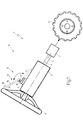
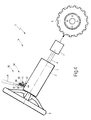
- the reference number 1 designates, as a whole, steering equipment for vehicles, in particular for agricultural vehicles, the said equipment comprising a steering unit 1a, which in turn comprises a tubular steering column 2 extending along an axis 3 and connected in a known way to a chassis (not illustrated) of the vehicle.
- a tubular transmission shaft 4 is mounted inside the steering column 2 co-axially with respect to the axis 3, and a steering wheel 5 is fitted on one end of the shaft 4 for controlling the steering of a pair of wheels 6 (only one of which is represented in Figure 1) by means of a hydraulic unit 7 of the type described in the patent application No. EP-A-1.142.773, which is integrally incorporated herein by reference.
- the steering unit 1a comprises a control device 8 acting upon the hydraulic unit 7 for varying a steering ratio, i.e., the ratio between the angle of rotation of the steering wheel 5 about the axis 3 and the angle of steering of the wheels 6, between a first relatively large value k1, which is characteristic of a first mode of operation, defined as “conventional steering", and a second relatively small value k2, which is characteristic of a second mode of operation, defined as "fast steering".
- a steering ratio i.e., the ratio between the angle of rotation of the steering wheel 5 about the axis 3 and the angle of steering of the wheels 6, between a first relatively large value k1, which is characteristic of a first mode of operation, defined as "conventional steering", and a second relatively small value k2, which is characteristic of a second mode of operation, defined as "fast steering".
- the device 8 comprises a switch 9 of a known type, which is connected to an electronic control unit (not illustrated) designed to selectively control operation of the hydraulic unit 7 in response to a signal coming from the switch 9.
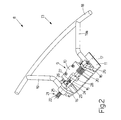
- the switch 9 comprises a fixed part 10 mounted on a substantially plane plate 11 fixed to the steering column 2 and a mobile part defined by an arm 12 (figure 3) hinged to the part 10 so as to oscillate relative thereto under the thrust of an actuator device 13, about a pivot axis 14 substantially perpendicular to the plate 11.
- the device 13 comprises a tubular shaft 15 coupled pivotally to two ribs 16 projecting from the plate 11.
- the shaft 15 is able to oscillate, with respect to the ribs 16, about a longitudinal axis 17 that is substantially orthogonal to the axes 3 and 14.
- the device 13 further comprises a control member 18, which substantially has the shape of a sector of a circle and is fixed to the shaft 15 by means of two arms 19, 19a fixed to the ends of the shaft 15.
- the member 18 is able to pivot about axis 17 under the thrust exerted by an operator and against the thrust of a cylindrical helical spring 20.
- Spring 20 is fitted on the shaft 15 co-axially with respect to the axis 17 and set between the plate 11 and arm 19a.
- the member 18 pivots about the axis 17 in a counterclockwise direction, as viewed in Figures 1 and 2, from a resting position (indicated by a dashed line in Figure 1), in which the member 18 is set at a given distance from the steering wheel 5, to an operative position (indicated by a solid line in Figure 1), in which the member 18 is set in a position which is substantially coaxial with respect to the axis 3.
- the member 18 is placed in the resting position whenever inadvertent actuation of the device 8 should be avoided.
- the member 18 is clamped in its resting and operative positions by means of a clamping device 21 comprising a release button 22, which is engaged in such a way that it can turn and slide axially through the shaft 15, and is angularly clamped on the shaft 15 by means of a pin 23, which extends outwards from an outer surface of the button 22 to engage, in a slidable and angularly fixed manner, a slit 24 made radially through the shaft 15.
- a clamping device 21 comprising a release button 22, which is engaged in such a way that it can turn and slide axially through the shaft 15, and is angularly clamped on the shaft 15 by means of a pin 23, which extends outwards from an outer surface of the button 22 to engage, in a slidable and angularly fixed manner, a slit 24 made radially through the shaft 15.
- the device 21 further comprises a cylindrical helical spring 25, which is fitted on the button 22 co-axially with respect to the axis 17.
- the spring 25 is provided between the shaft 15 and the button 22, and is designed to keep the button 22 in a clamping position ( Figures 2 and 3), in which the pin 23 is operable to engage an end-of-travel element 26 both when the member 18 is set in its resting or its operative position.
- the element 26, which is fixedly attached to one of the ribs 16, basically has the shape of a sector of a circle which is coaxial to the axis 17, and extends from one of the ribs 16 in the direction of the other rib 16.
- the arm 12 of the switch 9 is operated by means of a pin 27, which extends parallel to the axis 17 and projects from a central widened portion 28 of the shaft 15.
- the pin 27 is brought into touching contact with the arm 12 ( Figure 3) however initially without moving the arm 12.
- the pin 27 is operable to rotate the arm 12 about the axis 14 into a position for closing the switch 9 upon a further displacement of the member 18 (in a counterclockwise direction, as viewed in Figure 1, and in a clockwise direction, as viewed in Figure 3), against the thrust of the spring 20 and under the thrust exerted by the operator.
- the member 18 is moved from its operative position into an actuation position (not illustrated) until the arm 19a comes into contact with an end-of-travel element 29 projecting from the corresponding rib 16, parallel to the axis 17.
- the displacement of the member 18 from its resting position to its operative position is initiated by pushing the button 22 towards the nearby rib 16 along the axis 17 and into a releasing position, in which the pin 23 disengages from the element 26. Then, the member 18 is rotated about the axis 17 (in a counterclockwise direction, as viewed in Figures 1 and 2) against the thrust of the spring 20. Finally, both the button 22 and the member 18 are released in order to enable the button 22 to set itself once again in its clamping position and, consequently, to enable the pin 23 to engage the other side of element 26.
- the member 18 is provided with an encircling sleeve, which is located between the arms 19, 19a and is connected in a slidable way to the member 18.
- the sleeve is somewhat shorter than the distance between the two arms 19, 19a and is normally kept in a central position by means of two springs, which are set at the ends of the sleeve between the sleeve and the arms 19, 19a respectively.
- the slidable assembly of the sleeve on the member 18 enables the operator instead to turn the steering wheel 5 about the axis 3 with his hand and, at the same time, to displace the member 18 between its operative position and its actuation position by gripping the sleeve firmly.
- the presence of the sleeve thus prevents the need for the operator to slide his hand along the member 18. Only small movements of the sleeve are required considering that, once "fast steering" mode is chosen, only little rotation of the steering wheel 5 is needed to quickly turn the wheels 6.
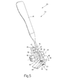
- a further embodiment shown in Figures 4 and 5 differs from what is illustrated in the previous figures in that the steering unit 1a comprises a different control device 30, which in turn comprises a switch 31 of a known type.
- the switch 31 is connected to an electronic control unit (not illustrated) operable to selectively control operation of the hydraulic unit 7 in response to a signal coming from the switch 31.
- the switch 31 comprises a fixed portion 32 mounted on a plate 33 fixed to the steering column 2 and a mobile portion defined by a button (not illustrated) coupled in a known way to the portion 32 for performing rectilinear displacements, with respect to the portion 32 and under the thrust of an actuator device 34, in a given direction 35 away from and towards a position for closing of the switch 31.
- the device 34 comprises a bolt 36, which extends through the plate 33 and has a longitudinal axis 37 transverse to the direction 35.
- the bolt 36 is engaged in such a way that it can turn and slide axially through a cylindrical spacer 38 and a washer 39, which are axially and angularly clamped on the bolt 36 by means of a locknut 40, screwed on one free end of the bolt 36 to tighten the spacer 38 and the washer 39 against the plate 33.
- the button (not illustrated) of the switch 31 is actuated by means of a control lever 41, which has a central hub 42 coaxial to the axis 37.
- the lever 41 extends upwards from the hub 42, and is coupled in such a way that it can turn and is axially fixed to the spacer 38 so as to oscillate, with respect to the plate 33, about the axis 37.
- the lever 41 is normally kept in an operative position ( Figure 5), in which the aforesaid button (not illustrated) is substantially set outside the portion 32 and inside a corresponding seat 43 made on the hub 42 by a cylindrical helical spring 44.
- the spring 44 is fitted on the spacer 38 coaxially with respect to the axis 37 and has two free ends set on opposite sides of two pins 46, 47 parallel to the axis 37.
- the pin 46 projects from the washer 39 towards the lever 41, whereas the pin 47 projects from the lever 41 towards the washer 39.
- the lever 41 is able to move about the axis 37, against the thrust of the spring 44 and under a thrust exerted by the operator indifferently either in the clockwise direction or in the counterclockwise direction, from its operative position to two actuation positions (not illustrated) of the switch 31.
- the aforesaid button (not illustrated) is substantially moved downwardly within the portion 32 under the thrust of the hub 42, thereby actuating the switch 31.
- the arrangement of the control devices 8, 30 on the steering column 2 thus enables the hydraulic unit 7 to be operated with relative ease and convenience in such a way that the steering ratio will assume the value k1 when the member 18 and the lever 41 set themselves in their operative positions and the value k2 when the member 18 and the lever 41 set themselves in their positions of actuation of the switches 9 and 31, respectively.
Landscapes
- Engineering & Computer Science (AREA)
- Chemical & Material Sciences (AREA)
- Combustion & Propulsion (AREA)
- Transportation (AREA)
- Mechanical Engineering (AREA)
- Steering Controls (AREA)
- Arrangement Or Mounting Of Control Devices For Change-Speed Gearing (AREA)
- Power Steering Mechanism (AREA)
- Steering-Linkage Mechanisms And Four-Wheel Steering (AREA)
Priority Applications (1)
| Application Number | Priority Date | Filing Date | Title |
|---|---|---|---|
| EP09163789A EP2098434B1 (de) | 2002-03-04 | 2003-02-25 | Lenkausstattung für eine Fahrzeuglenkung |
Applications Claiming Priority (2)
| Application Number | Priority Date | Filing Date | Title |
|---|---|---|---|
| ITBO20020107 | 2002-03-04 | ||
| IT2002BO000107A ITBO20020107A1 (it) | 2002-03-04 | 2002-03-04 | Apparecchiatura di sterzatura per veicoli |
Related Child Applications (1)
| Application Number | Title | Priority Date | Filing Date |
|---|---|---|---|
| EP09163789A Division EP2098434B1 (de) | 2002-03-04 | 2003-02-25 | Lenkausstattung für eine Fahrzeuglenkung |
Publications (3)
| Publication Number | Publication Date |
|---|---|
| EP1342641A2 true EP1342641A2 (de) | 2003-09-10 |
| EP1342641A3 EP1342641A3 (de) | 2004-01-02 |
| EP1342641B1 EP1342641B1 (de) | 2009-11-18 |
Family
ID=11439953
Family Applications (2)
| Application Number | Title | Priority Date | Filing Date |
|---|---|---|---|
| EP09163789A Expired - Lifetime EP2098434B1 (de) | 2002-03-04 | 2003-02-25 | Lenkausstattung für eine Fahrzeuglenkung |
| EP03100447A Expired - Lifetime EP1342641B1 (de) | 2002-03-04 | 2003-02-25 | Lenkausstattung für eine Fahrzeuglenkung |
Family Applications Before (1)
| Application Number | Title | Priority Date | Filing Date |
|---|---|---|---|
| EP09163789A Expired - Lifetime EP2098434B1 (de) | 2002-03-04 | 2003-02-25 | Lenkausstattung für eine Fahrzeuglenkung |
Country Status (5)
| Country | Link |
|---|---|
| US (1) | US6948583B2 (de) |
| EP (2) | EP2098434B1 (de) |
| AT (1) | ATE448987T1 (de) |
| DE (1) | DE60330084D1 (de) |
| IT (1) | ITBO20020107A1 (de) |
Cited By (2)
| Publication number | Priority date | Publication date | Assignee | Title |
|---|---|---|---|---|
| US6877582B2 (en) | 2003-03-05 | 2005-04-12 | Case, Llc | Steering equipment for vehicles |
| US6948583B2 (en) | 2002-03-04 | 2005-09-27 | Cnh America Llc | Steering equipment for vehicles |
Families Citing this family (2)
| Publication number | Priority date | Publication date | Assignee | Title |
|---|---|---|---|---|
| US7687729B2 (en) * | 2007-07-10 | 2010-03-30 | Grote Industries, Inc. | Processed bolt end useful in a turn signal switch assembly |
| CN110284912B (zh) * | 2019-07-20 | 2020-08-25 | 山西能源学院 | 一种矿用液压支柱自重力泄压缓冲装置 |
Citations (1)
| Publication number | Priority date | Publication date | Assignee | Title |
|---|---|---|---|---|
| DE19625966A1 (de) | 1996-06-28 | 1998-01-02 | Teves Gmbh Alfred | Im Bereich des Lenkrades angeordnete Schalterbaugruppe |
Family Cites Families (18)
| Publication number | Priority date | Publication date | Assignee | Title |
|---|---|---|---|---|
| US1792713A (en) * | 1928-11-28 | 1931-02-17 | Edward C Schmelzkopf | Signal switch for automobiles |
| US2778898A (en) * | 1952-10-31 | 1957-01-22 | Gen Motors Corp | Steering wheel assembly |
| DE946870C (de) | 1954-05-16 | 1956-08-09 | Auto Union G M B H | Hupenknopf am Lenkrad fuer Fahrzeuge |
| US3308427A (en) * | 1963-12-02 | 1967-03-07 | Emerson E Hess | Passing signal system for motor vehicles |
| US3881076A (en) * | 1974-04-12 | 1975-04-29 | Ford Motor Co | Steering column vehicle switch assembly having rotary and lineal movement |
| US4180713A (en) * | 1975-06-25 | 1979-12-25 | Societe Anonyme Automobiles Citroen | Switch control unit for automobile vehicle |
| US4078628A (en) * | 1976-08-16 | 1978-03-14 | The United States Of America As Represented By The Department Of Health, Education And Welfare | Double-wheel automotive hand control system |
| US4537089A (en) * | 1983-01-14 | 1985-08-27 | J. I. Case Company | Steering wheel |
| DE3421602A1 (de) * | 1984-06-09 | 1985-12-12 | Iveco Magirus AG, 7900 Ulm | Schalt-lenkrad-anordnung fuer ein kraftfahrzeug |
| JP3784542B2 (ja) * | 1998-07-28 | 2006-06-14 | アルプス電気株式会社 | ターンシグナルスイッチ |
| JP3335146B2 (ja) * | 1999-08-25 | 2002-10-15 | 本田技研工業株式会社 | ステアリングホイール |
| JP2001076593A (ja) * | 1999-09-07 | 2001-03-23 | Yazaki Corp | スイッチ装置 |
| DE20004953U1 (de) | 2000-03-10 | 2000-08-10 | Petri Ag, 63743 Aschaffenburg | Lenkrad für Kraftfahrzeuge mit einer Schalteinrichtung zum Betätigen einer elektrischen Funktionsgruppe eines Kraftfahrzeugs |
| ITBO20000188A1 (it) * | 2000-04-04 | 2001-10-04 | New Holland Italia Spa | Apparecchiatura idraulica di sterzatura . |
| FR2814405B1 (fr) * | 2000-09-22 | 2002-12-20 | Ecia Equip Composants Ind Auto | Ensemble de direction a coussin central fixe, coussin central et vehicule automobile correspondants |
| US6538220B2 (en) * | 2001-04-23 | 2003-03-25 | Trw Inc. | Switch pod assembly |
| ITBO20020107A1 (it) | 2002-03-04 | 2003-09-04 | New Holland Italia Spa | Apparecchiatura di sterzatura per veicoli |
| ITBO20020106A1 (it) | 2002-03-04 | 2003-09-04 | New Holland Italia Spa | Apparecchiatura di sterzatura per veicoli |
-
2002
- 2002-03-04 IT IT2002BO000107A patent/ITBO20020107A1/it unknown
-
2003
- 2003-02-25 AT AT03100447T patent/ATE448987T1/de not_active IP Right Cessation
- 2003-02-25 EP EP09163789A patent/EP2098434B1/de not_active Expired - Lifetime
- 2003-02-25 EP EP03100447A patent/EP1342641B1/de not_active Expired - Lifetime
- 2003-02-25 DE DE60330084T patent/DE60330084D1/de not_active Expired - Lifetime
- 2003-03-05 US US10/382,151 patent/US6948583B2/en not_active Expired - Lifetime
Patent Citations (1)
| Publication number | Priority date | Publication date | Assignee | Title |
|---|---|---|---|---|
| DE19625966A1 (de) | 1996-06-28 | 1998-01-02 | Teves Gmbh Alfred | Im Bereich des Lenkrades angeordnete Schalterbaugruppe |
Cited By (2)
| Publication number | Priority date | Publication date | Assignee | Title |
|---|---|---|---|---|
| US6948583B2 (en) | 2002-03-04 | 2005-09-27 | Cnh America Llc | Steering equipment for vehicles |
| US6877582B2 (en) | 2003-03-05 | 2005-04-12 | Case, Llc | Steering equipment for vehicles |
Also Published As
| Publication number | Publication date |
|---|---|
| EP1342641B1 (de) | 2009-11-18 |
| ITBO20020107A0 (it) | 2002-03-04 |
| EP2098434A1 (de) | 2009-09-09 |
| ITBO20020107A1 (it) | 2003-09-04 |
| US20040173400A1 (en) | 2004-09-09 |
| DE60330084D1 (de) | 2009-12-31 |
| EP1342641A3 (de) | 2004-01-02 |
| ATE448987T1 (de) | 2009-12-15 |
| US6948583B2 (en) | 2005-09-27 |
| EP2098434B1 (de) | 2013-01-02 |
Similar Documents
| Publication | Publication Date | Title |
|---|---|---|
| US5439252A (en) | Dual pivot steering column | |
| JP2647476B2 (ja) | 調整式かじ取ハンドル | |
| JP2616955B2 (ja) | 傾斜伸縮操舵柱装置 | |
| US5361646A (en) | Locking mechanism | |
| US7178422B2 (en) | Electrical tilt and telescope locking mechanism | |
| US20080238068A1 (en) | Vehicle steering column structure | |
| US20090266195A1 (en) | Adjustable steering column assembly | |
| US6131481A (en) | Steering column | |
| EP1342641A2 (de) | Lenkausstattung für eine Fahrzeuglenkung | |
| AU681174B2 (en) | Depressed park windshield wiper mechanism | |
| JPH02502861A (ja) | 車両を運転するための制御機構 | |
| KR100197174B1 (ko) | 스틱레버장치 | |
| US4221277A (en) | Device for automatically returning a transmission control to neutral | |
| JP2003028293A (ja) | 車両用変速制御装置 | |
| US20050109153A1 (en) | Steering wheel assembly | |
| US5220985A (en) | Shift range selection mechanism for an automatic transmission | |
| US20040099086A1 (en) | Pole for hand pallet truck | |
| JP2012218543A (ja) | 車両のステアリング装置 | |
| US6736025B2 (en) | Vehicular foot-operated parking brake control apparatus | |
| JPH03504837A (ja) | ブレーキを掛けるとともに車両のトランスミッションを中立化するための制御機構 | |
| KR100569953B1 (ko) | 자동차의 스티어링 컬럼 | |
| EP2633208B1 (de) | Steuerungsvorrichtung für ein raupenfahrzeug | |
| EP1997711B1 (de) | Lenkausstattung für ein Fahrzeug | |
| US2128969A (en) | Hand brake operating mechanism | |
| JPH065969Y2 (ja) | キャブチルトの操作レバー装置 |
Legal Events
| Date | Code | Title | Description |
|---|---|---|---|
| PUAI | Public reference made under article 153(3) epc to a published international application that has entered the european phase |
Free format text: ORIGINAL CODE: 0009012 |
|
| AK | Designated contracting states |
Kind code of ref document: A2 Designated state(s): AT BE BG CH CY CZ DE DK EE ES FI FR GB GR HU IE IT LI LU MC NL PT SE SI SK TR |
|
| AX | Request for extension of the european patent |
Extension state: AL LT LV MK RO |
|
| PUAL | Search report despatched |
Free format text: ORIGINAL CODE: 0009013 |
|
| AK | Designated contracting states |
Kind code of ref document: A3 Designated state(s): AT BE BG CH CY CZ DE DK EE ES FI FR GB GR HU IE IT LI LU MC NL PT SE SI SK TR |
|
| AX | Request for extension of the european patent |
Extension state: AL LT LV MK RO |
|
| AKX | Designation fees paid | ||
| 17P | Request for examination filed |
Effective date: 20040826 |
|
| RBV | Designated contracting states (corrected) |
Designated state(s): AT BE BG CH CY CZ DE DK EE ES FI FR GB GR HU IE IT LI LU MC NL PT SE SI SK TR |
|
| REG | Reference to a national code |
Ref country code: DE Ref legal event code: 8566 |
|
| 17Q | First examination report despatched |
Effective date: 20080418 |
|
| GRAP | Despatch of communication of intention to grant a patent |
Free format text: ORIGINAL CODE: EPIDOSNIGR1 |
|
| GRAS | Grant fee paid |
Free format text: ORIGINAL CODE: EPIDOSNIGR3 |
|
| GRAA | (expected) grant |
Free format text: ORIGINAL CODE: 0009210 |
|
| AK | Designated contracting states |
Kind code of ref document: B1 Designated state(s): AT BE BG CH CY CZ DE DK EE ES FI FR GB GR HU IE IT LI LU MC NL PT SE SI SK TR |
|
| REG | Reference to a national code |
Ref country code: GB Ref legal event code: FG4D |
|
| REG | Reference to a national code |
Ref country code: CH Ref legal event code: EP |
|
| REG | Reference to a national code |
Ref country code: IE Ref legal event code: FG4D |
|
| REF | Corresponds to: |
Ref document number: 60330084 Country of ref document: DE Date of ref document: 20091231 Kind code of ref document: P |
|
| REG | Reference to a national code |
Ref country code: NL Ref legal event code: VDEP Effective date: 20091118 |
|
| PG25 | Lapsed in a contracting state [announced via postgrant information from national office to epo] |
Ref country code: SE Free format text: LAPSE BECAUSE OF FAILURE TO SUBMIT A TRANSLATION OF THE DESCRIPTION OR TO PAY THE FEE WITHIN THE PRESCRIBED TIME-LIMIT Effective date: 20091118 Ref country code: PT Free format text: LAPSE BECAUSE OF FAILURE TO SUBMIT A TRANSLATION OF THE DESCRIPTION OR TO PAY THE FEE WITHIN THE PRESCRIBED TIME-LIMIT Effective date: 20100318 Ref country code: FI Free format text: LAPSE BECAUSE OF FAILURE TO SUBMIT A TRANSLATION OF THE DESCRIPTION OR TO PAY THE FEE WITHIN THE PRESCRIBED TIME-LIMIT Effective date: 20091118 Ref country code: ES Free format text: LAPSE BECAUSE OF FAILURE TO SUBMIT A TRANSLATION OF THE DESCRIPTION OR TO PAY THE FEE WITHIN THE PRESCRIBED TIME-LIMIT Effective date: 20100228 |
|
| PG25 | Lapsed in a contracting state [announced via postgrant information from national office to epo] |
Ref country code: CY Free format text: LAPSE BECAUSE OF FAILURE TO SUBMIT A TRANSLATION OF THE DESCRIPTION OR TO PAY THE FEE WITHIN THE PRESCRIBED TIME-LIMIT Effective date: 20091118 Ref country code: SI Free format text: LAPSE BECAUSE OF FAILURE TO SUBMIT A TRANSLATION OF THE DESCRIPTION OR TO PAY THE FEE WITHIN THE PRESCRIBED TIME-LIMIT Effective date: 20091118 |
|
| PG25 | Lapsed in a contracting state [announced via postgrant information from national office to epo] |
Ref country code: BE Free format text: LAPSE BECAUSE OF FAILURE TO SUBMIT A TRANSLATION OF THE DESCRIPTION OR TO PAY THE FEE WITHIN THE PRESCRIBED TIME-LIMIT Effective date: 20091118 Ref country code: AT Free format text: LAPSE BECAUSE OF FAILURE TO SUBMIT A TRANSLATION OF THE DESCRIPTION OR TO PAY THE FEE WITHIN THE PRESCRIBED TIME-LIMIT Effective date: 20091118 |
|
| PG25 | Lapsed in a contracting state [announced via postgrant information from national office to epo] |
Ref country code: EE Free format text: LAPSE BECAUSE OF FAILURE TO SUBMIT A TRANSLATION OF THE DESCRIPTION OR TO PAY THE FEE WITHIN THE PRESCRIBED TIME-LIMIT Effective date: 20091118 Ref country code: DK Free format text: LAPSE BECAUSE OF FAILURE TO SUBMIT A TRANSLATION OF THE DESCRIPTION OR TO PAY THE FEE WITHIN THE PRESCRIBED TIME-LIMIT Effective date: 20091118 Ref country code: BG Free format text: LAPSE BECAUSE OF FAILURE TO SUBMIT A TRANSLATION OF THE DESCRIPTION OR TO PAY THE FEE WITHIN THE PRESCRIBED TIME-LIMIT Effective date: 20100218 Ref country code: NL Free format text: LAPSE BECAUSE OF FAILURE TO SUBMIT A TRANSLATION OF THE DESCRIPTION OR TO PAY THE FEE WITHIN THE PRESCRIBED TIME-LIMIT Effective date: 20091118 |
|
| PG25 | Lapsed in a contracting state [announced via postgrant information from national office to epo] |
Ref country code: CZ Free format text: LAPSE BECAUSE OF FAILURE TO SUBMIT A TRANSLATION OF THE DESCRIPTION OR TO PAY THE FEE WITHIN THE PRESCRIBED TIME-LIMIT Effective date: 20091118 Ref country code: SK Free format text: LAPSE BECAUSE OF FAILURE TO SUBMIT A TRANSLATION OF THE DESCRIPTION OR TO PAY THE FEE WITHIN THE PRESCRIBED TIME-LIMIT Effective date: 20091118 |
|
| PLBE | No opposition filed within time limit |
Free format text: ORIGINAL CODE: 0009261 |
|
| STAA | Information on the status of an ep patent application or granted ep patent |
Free format text: STATUS: NO OPPOSITION FILED WITHIN TIME LIMIT |
|
| REG | Reference to a national code |
Ref country code: CH Ref legal event code: PL |
|
| 26N | No opposition filed |
Effective date: 20100819 |
|
| PG25 | Lapsed in a contracting state [announced via postgrant information from national office to epo] |
Ref country code: CH Free format text: LAPSE BECAUSE OF NON-PAYMENT OF DUE FEES Effective date: 20100228 Ref country code: GR Free format text: LAPSE BECAUSE OF FAILURE TO SUBMIT A TRANSLATION OF THE DESCRIPTION OR TO PAY THE FEE WITHIN THE PRESCRIBED TIME-LIMIT Effective date: 20100219 Ref country code: MC Free format text: LAPSE BECAUSE OF NON-PAYMENT OF DUE FEES Effective date: 20100301 Ref country code: LI Free format text: LAPSE BECAUSE OF NON-PAYMENT OF DUE FEES Effective date: 20100228 |
|
| PG25 | Lapsed in a contracting state [announced via postgrant information from national office to epo] |
Ref country code: IE Free format text: LAPSE BECAUSE OF NON-PAYMENT OF DUE FEES Effective date: 20100225 |
|
| PG25 | Lapsed in a contracting state [announced via postgrant information from national office to epo] |
Ref country code: HU Free format text: LAPSE BECAUSE OF FAILURE TO SUBMIT A TRANSLATION OF THE DESCRIPTION OR TO PAY THE FEE WITHIN THE PRESCRIBED TIME-LIMIT Effective date: 20100519 Ref country code: LU Free format text: LAPSE BECAUSE OF NON-PAYMENT OF DUE FEES Effective date: 20100225 |
|
| PG25 | Lapsed in a contracting state [announced via postgrant information from national office to epo] |
Ref country code: TR Free format text: LAPSE BECAUSE OF FAILURE TO SUBMIT A TRANSLATION OF THE DESCRIPTION OR TO PAY THE FEE WITHIN THE PRESCRIBED TIME-LIMIT Effective date: 20091118 |
|
| REG | Reference to a national code |
Ref country code: DE Ref legal event code: R082 Ref document number: 60330084 Country of ref document: DE Representative=s name: PATENTANWAELTE WALLACH, KOCH & PARTNER, DE |
|
| REG | Reference to a national code |
Ref country code: DE Ref legal event code: R082 Ref document number: 60330084 Country of ref document: DE Representative=s name: PATENTANWAELTE WALLACH, KOCH & PARTNER, DE Effective date: 20140623 Ref country code: DE Ref legal event code: R081 Ref document number: 60330084 Country of ref document: DE Owner name: CNH INDUSTRIAL ITALIA S.P.A., IT Free format text: FORMER OWNER: CNH ITALIA S.P.A., MODENA, IT Effective date: 20140623 Ref country code: DE Ref legal event code: R082 Ref document number: 60330084 Country of ref document: DE Representative=s name: PATENTANWAELTE WALLACH, KOCH, DR. HAIBACH, FEL, DE Effective date: 20140623 |
|
| REG | Reference to a national code |
Ref country code: FR Ref legal event code: CD Owner name: CNH INDUSTRIAL ITALIA S.P.A. Effective date: 20150313 |
|
| REG | Reference to a national code |
Ref country code: FR Ref legal event code: PLFP Year of fee payment: 14 |
|
| REG | Reference to a national code |
Ref country code: FR Ref legal event code: PLFP Year of fee payment: 15 |
|
| PGFP | Annual fee paid to national office [announced via postgrant information from national office to epo] |
Ref country code: FR Payment date: 20170111 Year of fee payment: 15 |
|
| PGFP | Annual fee paid to national office [announced via postgrant information from national office to epo] |
Ref country code: IT Payment date: 20170203 Year of fee payment: 15 |
|
| PGFP | Annual fee paid to national office [announced via postgrant information from national office to epo] |
Ref country code: DE Payment date: 20180112 Year of fee payment: 16 Ref country code: GB Payment date: 20180112 Year of fee payment: 16 |
|
| REG | Reference to a national code |
Ref country code: FR Ref legal event code: ST Effective date: 20181031 |
|
| PG25 | Lapsed in a contracting state [announced via postgrant information from national office to epo] |
Ref country code: IT Free format text: LAPSE BECAUSE OF NON-PAYMENT OF DUE FEES Effective date: 20180225 Ref country code: FR Free format text: LAPSE BECAUSE OF NON-PAYMENT OF DUE FEES Effective date: 20180228 |
|
| REG | Reference to a national code |
Ref country code: DE Ref legal event code: R119 Ref document number: 60330084 Country of ref document: DE |
|
| GBPC | Gb: european patent ceased through non-payment of renewal fee |
Effective date: 20190225 |
|
| PG25 | Lapsed in a contracting state [announced via postgrant information from national office to epo] |
Ref country code: GB Free format text: LAPSE BECAUSE OF NON-PAYMENT OF DUE FEES Effective date: 20190225 Ref country code: DE Free format text: LAPSE BECAUSE OF NON-PAYMENT OF DUE FEES Effective date: 20190903 |